Article

Human-Induced Vibration Analysis and Reduction Design for Super Long Span Pedestrian Arch Bridges with Tuned Mass Dampers

School of Civil Engineering, Chang’an University, Xi’an 710064, China
*
Author to whom correspondence should be addressed.
Appl. Sci. 2023, 13(14), 8263; https://doi.org/10.3390/app13148263
Submission received: 12 June 2023 / Revised: 8 July 2023 / Accepted: 13 July 2023 / Published: 17 July 2023
(This article belongs to the Section Civil Engineering)

Abstract

:
With the increasing demands on span length, aesthetics, and urban landscapes of pedestrian bridges, the fundamental frequency of pedestrian bridges is continuing to decrease, and their vibration and walking comfort issues are becoming increasingly prominent. The pedestrian load model of the pedestrian bridge was introduced here referencing current design specifications, and a spatial finite element model was established to study the dynamic characteristics of the case of a long-span pedestrian arch bridge. The comfort of the bridge under human-induced vibration was analyzed using the time history analysis method. According to the optimal damper parameter expression, the design parameters of the damper were obtained. In addition, the vibration reduction effects of different generalized mass ratios were analyzed, and the damping effects of setting the tuned mass damper (TMD) at different positions were compared. The results indicated that setting the TMD on the bridge can enhance the damping effect, and the transverse vibration can be suppressed by setting TMDs on both the arch ribs and the bridge deck. The research content could provide recommended parameters for the vibration reduction design of long-span pedestrian arch bridges.

1. Introduction

With the wide application of high-strength and lightweight materials and the improvement of structural analysis technology, the development of bridges tends to be large-span, slim, and light types. However, light, flexible, low damping large-span bridges are prone to vibration problems.
Seismic loads and wind loads are typically taken into account in the dynamic analysis of bridge structures, while the crowd loads are designed as static loads whose dynamic impacts are frequently ignored.
For large-span bridges of highways and railroads, the error brought by such treatment can be neglected in most cases due to the small proportion of crowd loads, however, the dynamic response caused by crowd loads is important for pedestrian bridges and non-motorized passenger bridges. Especially in the design of large-span pedestrian bridges, neglecting the potential crowd-induced vibration response during operation can lead to inaccurate prediction of structural response. Accidents attributed to vibration caused by crowd loads have been recurrent on pedestrian bridges, with notable instances being the Millennium Bridge in London, and the T-Bridge in Japan [1]. Furthermore, numerous other pedestrian bridges have encountered vibration issues under pedestrian loading, such as the Mape Valley Great Suspension Bridge [2], the Tudor Park Bridge [3], the Changi Mezzaine Bridge [4], and the Solferino Bridge.
For bridges with vertical fundamental frequencies close to pedestrian step frequencies, there are two damping methods when considering the bridge structure itself: the frequency adjustment method and the vibration damping method. The purpose of the frequency adjustment method is to avoid the sensitive range of frequency in the structure by increasing the static stiffness, and different requirements of the fundamental frequency of pedestrian bridges have been proposed for different standards [5,6,7,8,9]. However, the structural resonance caused by the higher step frequency load component of pedestrian traffic is not considered in this method, and the structural dynamic response from a quantitative perspective not reflected. As for the vibration damping method, the structural resonance response is reduced by increasing the damping of the pedestrian bridge structure, which has been widely accepted as an effective method to reduce the dynamic response of structures. There are many types of classical control devices to increase the damping of structures such as viscous dampers [10,11,12], tuned mass dampers (TMDs) [13], restrained flexural corrugated plates [14], and actively controlled pre-stressing tendons [15,16].
The comfort and the vibration-damping design of pedestrian bridges have been widely studied by experts and scholars [17,18,19,20]. Considering the crowd-induced control, a generic optimization method was proposed by Li et al. [21] to solve the vibration problem of pedestrian bridges. The vibration response of a 142 m long three-span continuous pedestrian bridge under pedestrian loads was tested, and the results of the experimental dynamics tests and the numerical simulation were compared [22]. What is more, TMD has been widely studied and applied in many practical structures [23,24]. The dynamic response of large-span bridges installed with TMDs was analyzed, and the results showed that the torsional and vertical response of the bridge under wind loads and traffic loads can be effectively controlled by a TMD system [25,26]. The mechanical performance of steel pedestrian bridges with and without TMD were investigated using experimental and numerical simulation methods by Poovarodom et al. [27], and it was found that the structural response induced by pedestrians can be reduced by TMD; the degree of which depended on the type of human excitation. According to German pedestrian bridge design guidelines, Song [28] evaluated the comfort of a bridge with TMD for vibration damping treatment using the time history analysis method. In addition, different design suggestions of TMD have been proposed by scholars based on their own research. A conventional design method for TMD was proposed by Den [29], and Werkle [30] who used a 45 m span pedestrian bridge as an example to verify the accuracy of the optimization criterion advanced by Den. Fan [31] studied the problems of the TMD arrangement position, the optimal value of the optimal frequency ratio, as well as the optimal damping ratio of the system and vibration damping effect, and put forward corresponding design suggestions.
In this paper, a large-span pedestrian arch bridge was used as the research object, and the self-vibration characteristic of the structure was studied using numerical simulation methods. The pedestrian excitation force was simplified and then input into the model using simple harmonic load, while the comfort of the bridge under human-induced vibration was analyzed using the time history analysis method. What is more, the design parameters of the dampers were obtained according to the optimal expression of the damper parameters from existing research, and the damping effects of different generalized mass ratios were contrasted. The damping efficiency of the bridge was compared under two different TMD installation positions: TMD on the bridge decks and TMD on both decks and arch ribs.

2. Pedestrian Load Model

2.1. Single-Person Foot Force Model

The vibration of the pedestrian bridge is caused by the dynamic load of the crowd. The pedestrian bridge will generate a dynamic force of time-range force under the influence of acceleration changes during the crowd movement, which contains three components in three directions: namely, the vertical force along the direction of gravity, the horizontal lateral force perpendicular to the walking direction, and the horizontal longitudinal force along the walking direction. The single person load measured by Andriac-chi [32] with the force plate method was selected as the load model in this paper.
However, the environment of footstep force loads measured on a fixed platform was different from the actual environment of pedestrians crossing a pedestrian bridge. When the self-oscillation frequency of the bridge is similar to the frequency of the pedestrian’s pace, a locking phenomenon where pedestrians adjust their pace to synchronize with the bridge vibration will occur. After the vibration event of the Millennium Bridge, experiments and studies on the lateral vibration of pedestrian foot forces were conducted [33,34], and the results indicated that the synchronization rate of the pedestrian and the main beam is an important factor affecting the lateral response of the main beam. Considering the above factors, the pedestrian foot load in a vibrating environment was investigated, and a time function for the dynamic load of a single human footstep was proposed using the statistical analysis method [35]:
F p ( t ) = W + W i = 1 n α i sin ( 2 π i f p t φ i )
where fp is the pedestrian step frequency, which is equal to the total number of steps per second when calculating the vertical load and the lateral and vertical forces. Since there is only one cycle of change for each step of the left and right foot, it is half of the vertical value. W is the average pedestrian gravity. αi is called the simple harmonic dynamic load factor of the i-th order, which is expressed as follows:
α 1 = 0.41 f p 0.39 0.56 α 2 = 0.069 + 0.056 f p α 3 = 0.033 + 0.064 f p
The product i is the magnitude of the first-order dynamic load. (φi, denotes the initial phase of the i-th order dynamic load which is usually taken as φ1 = 0, thus, φi, i = 2, 3, 4… are the phase difference of the i-th order dynamic load to the first order dynamic load. The value of Fourier series order n is related to the required degree of approximation. It is generally considered that the first three orders of vertical loads, the first two orders of longitudinal loads, and the first order of transverse loads have sufficient accuracy. Numerous studies have shown that the dynamic load factor a is an increasing function of the step frequency; the vertical dynamic load coefficient. The values of the above parameters are given in Ref. [36].
It should be noted that the above mathematical load model of a single human footstep force is the summation of the static load expressed in the Fourier series and several simple harmonic dynamic loads. It is generally considered that the first three orders of vertical loads, the first two orders of longitudinal loads, and the first order of lateral loads have sufficient accuracy.

2.2. Multi-Person Foot Force Model

The correlation between pedestrians and the coupling effect between pedestrians and bridge structures led to difficulties in calculating and simulating the multi-person load. Hence, for the convenience of calculation, multi-person loads were classified into three types: small groups walking in pairs, low-density crowds walking freely, and high-density crowds moving [36].
The dynamic foot force load of a group of pedestrians can be estimated by multiplying the first-order harmonic component of a single foot force load by the number of people in the group:
F p ( t ) = W α sin ( 2 π f p t ) n
where n is the number of people in the group.
For the low-density crowd walking freely, it is assumed that there is a uniformly distributed crowd flow with speed of 1.5 m/s, and the total number of people maintained on the bridge, n, is constant. The step frequency fp of these n people obeys normal distribution, and its mean value is exactly equal to the frequency of the i-th order mode of the bridge fi. Simultaneously, the phase difference ψ consisting of n individuals is uniformly distributed between 0–2π, so that the step frequency and phase of the j-th person on the bridge can be expressed as follows:
f j = f i + σ μ j
ψ j = 2 π v j
where μj is the standard normal distribution random number; νj is a uniformly distributed random number in the interval (0, 1).
Due to the difficulties in synchronizing the second-, third- and higher-order components of the vertical load, only the first-order component of the vertical load is considered. Then the load of the j-th individual at time t is as follows:
F j ( t ) = W α sin ( 2 π f j t ψ j ) x = 1.5 t
Assuming the i-th order vibration function is φi(x) and the damping of the vibration mode is ξ, the time history curve of the maximum acceleration response can be calculated by the theory of structural dynamics. Applying the Monte Carlo method, a sufficient number of time history sample curves can be obtained and graded according to the maximum acceleration. The number of samples at each level are counted to ensure that the maximum acceleration of the bridge is excited. The total length of the calculated time course is twice as long as the single pedestrian passing the bridge at time T (equal to the bridge length divided by the speed 1.5 m/s), i.e., 2 T.
Then, it is assumed that there are np (np < n) pedestrians uniformly distributed on the same bridge of the same order of vibration, whose step frequency is equal to fi, and the phase difference between each other, that is, ψi = 0, and the direction of the applied force always take the direction of increasing displacement. In this way, the action of each pedestrian is to produce the maximum acceleration of the bridge, if the maximum acceleration of this np pedestrian is equal to the maximum acceleration produced by the n pedestrians walking randomly in front, then np is the equivalent number of the n pedestrians walking randomly and completely synchronized.
According to a large number of numerical simulations using the random variable method, the equivalent crowd size for a low-density crowd walking freely proposed by the French Guide is calculated as below:
n p = 10.8 n ξ i   ( when   the   crowd   density   <   1.0   person / m 2 )
This formula assumes that at the i-th order of vibration of a bridge, there are np pedestrians uniformly distributed on the bridge; not only is the step frequency equal to fi, no phase differences occur between each other, and the direction of the applied force always takes the direction of increasing displacement. In this way, the role of each pedestrian is to make the bridge produce the maximum acceleration; if the np pedestrians produce the maximum acceleration and the fronts of the n pedestrians walking randomly produce the maximum acceleration equally, then np represents the n pedestrians walking randomly, equivalent to the number of fully synchronized.
The above equations transform the problem of calculating the maximum acceleration of n pedestrians walking freely and randomly on the bridge (but moving at the same speed) into a problem of calculating the maximum acceleration of a perfectly synchronized np pedestrian, which greatly simplifies the problem.
When the density of pedestrians on the bridge exceeds 1.0 person/m2, the pedestrians are no longer free to walk according to their own wishes and habits because of the small distance between the front and back of the pedestrians. It was found that the synchronization phenomenon was greatly influenced by the pedestrian vision. Therefore, the flow of a continuous high-density crowd on the bridge can be considered as a continuous material flow with a much greater probability of synchronization than with a low-density crowd. The step frequencies between pedestrians in the high-density crowd condition are synchronized, and only the phases are different [37,38]. Following the same random probability distribution simulation method, the equivalent number of pedestrians in the high-density condition is summarized by this formula:
n p = 1.85 n   ( when   the   crowd   density   >   1.0   person / m 2 )
The above formula was also used in the German Pedestrian Bridge Design Guide EN03 [39].

3. Analysis of Structural Dynamic Response under Pedestrian Load Excitation

3.1. Establishment of FE Models

A pedestrian arch bridge in Xi’an was regarded as the research object in this paper. The pedestrian bridge is a medium-bearing arch bridge with a calculated span of 120 m, and a sagittal span ratio of 1/5. The bridge arch rib adopts a rectangular steel box cross-section, with an internal inclination of 7.5°. The deck system of the bridge is the beam lattice system composed of I-beams, with a total deck length of about 124 m. The finite element model (FE model) of the whole bridge was established using Midas Civil, with a 7 degrees of freedom beam unit simulating arch ribs, pile foundations, and deck longitudinal and transverse beams, while the plate unit was applied to simulate the bridge deck slab. The elastic connection simulation was adopted in the support of the whole bridge boundary and constraint conditions. The FE model of the case bridge is shown in Figure 1.

3.2. Structural Dynamic Characteristics Analysis

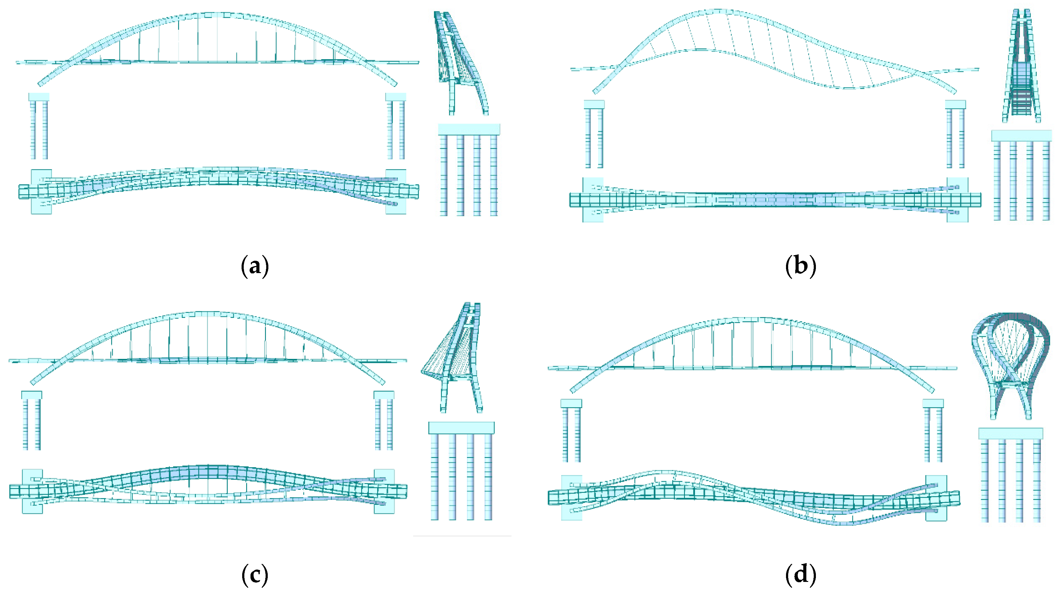
The structure eigenvalue analysis of the bridge was conducted, and the results are presented in Table 1. The structural vibration diagrams are shown in Figure 2.
According to the self-vibration modal analysis, it can be expressed that the bridge deck system and the arch ribs appear to vibrate synchronously, and the vibration of the arch ribs is coupled with the vibration of the bridge deck. In addition, the results shown in Table 1 and Figure 2 indicated that the 1st order frequency of the lateral vibration was 1.1509 Hz, and the vibration pattern was characterized by the lateral bending of the bridge deck and arch ribs. The 1st order frequency of the vertical vibration was 1.4277 Hz, and the vibration pattern was characterized by the vertical bending of the bridge deck. What is more, the 3rd and 5th order modes are also vertical vibration modes with frequencies of 1.4462 Hz and 2.4999 Hz, respectively, which are within the range of the pedestrian step frequency, resulting in the possibility of resonance.

3.3. Human-Induced Vibration Response Analysis

Combined with the sensitive frequency range evaluation guidelines of the German and French codes, the sensitive frequency range for vertical vibration was 1.40–2.40 Hz, and for lateral vibration was 0.50–1.20 Hz. The first order vertical frequency of this bridge was 1.43 Hz and the 1st order lateral vibration frequency 1.15 Hz. It is necessary to check whether the acceleration response under pedestrian loads meets the walking comfort conditions.
The pedestrian traffic class of footbridges was divided into five classes, namely TC1, TC2, TC3, TC4, and TC5. The corresponding pedestrian density (d0) is a group of 15 p (d0 = 15 p/BL, B = width of deck, L = length of deck), 0.2, 0.5, 1.0, and 1.5 p/m2, respectively [40]. Considering that this bridge has a larger pedestrian density during holidays, a high crowd density of d = 1.5 (P/m2) and a bridge deck area of S = 496 m2 were chosen. The total number of passengers was n = d × S = 744, which can be equivalent as 50 people walking on the bridge evenly:
n = 1.85 n / S = 0 . 1017 ( P / m 2 )
The simple harmonic walking force loads at equivalent crowd synchronization are the following:
p ( t ) = P × cos ( 2 π f s t ) × n × κ
where fs is the step frequency (assumed to be equal to the footbridge fundamental frequency), P is the vertical and lateral load amplitude for a step frequency equal to the walking force of a single person, taken as 280 N in the vertical direction and 35 N in the lateral direction, and a discount factor introduced to take into account the probability of the step frequency being close to the critical value of the variation range of the fundamental frequency [39].
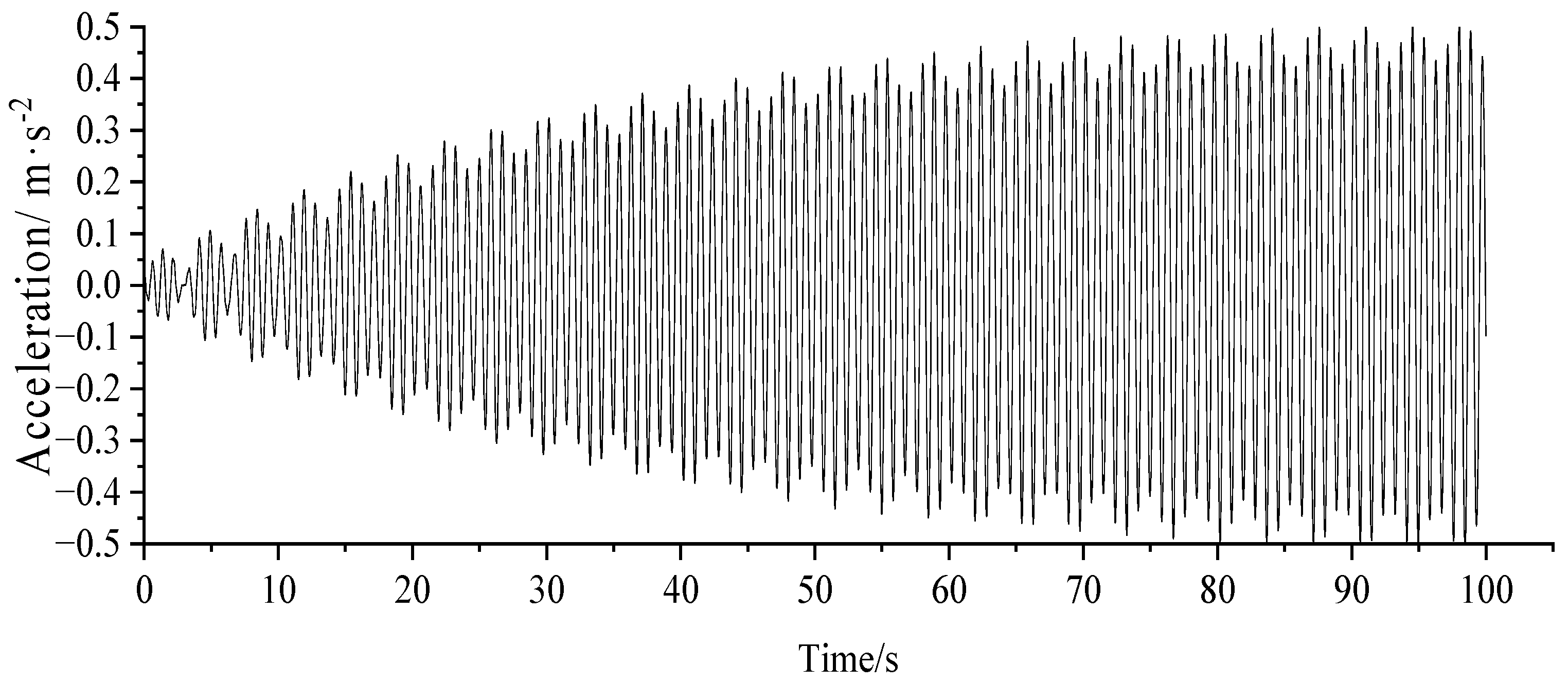
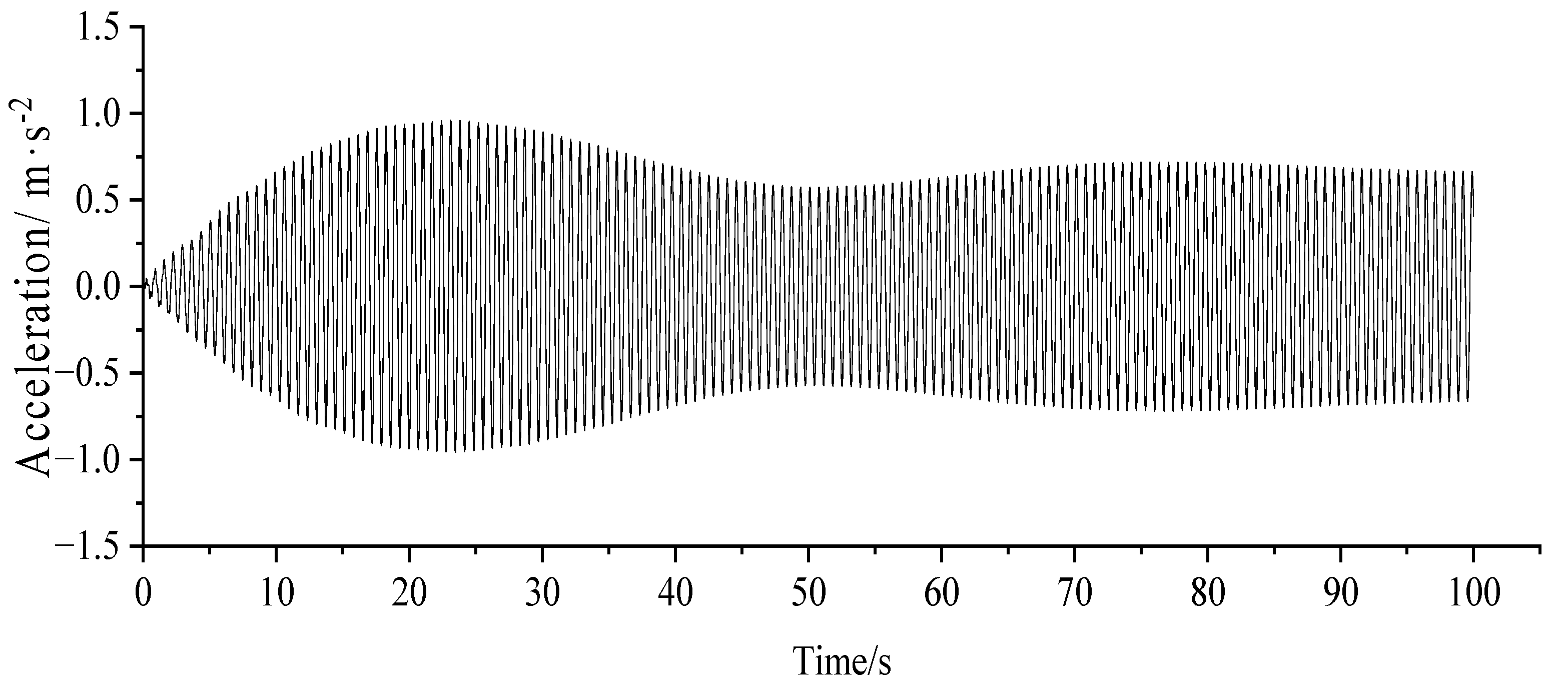
The vertical and lateral simple harmonic force walking loads were loaded into the model, and the results are shown in Figure 3 and Figure 4.
It is indicated in Figure 3 and Figure 4 that the maximum lateral acceleration of the pedestrian arch bridge was of 0.511 m/s2 at mid-span under lateral simple harmonic loading, and the maximum vertical acceleration of 2.528 m/s2 at 1/4 L under vertical simple harmonic loading; all these vibrations were within the risk ranges [32].

4. Criteria for Comfort Evaluation

The perception of humans for vibration is a complex issue as different people have different feelings for the same vibration source, or even the same person has a different feeling for the same vibration source at a different time. Due to the discomfort for pedestrians caused by the large vibration of a pedestrian bridge under walking forces, assessment methods of comfort indicators were proposed for many standards in different countries according to the limit of the vibration that the human body can withstand.
The vertical vibration comfort limit curve (alim = 0.5 f 0.5) proposed by Blanchard [41] for footbridges was used in bridge-design guidelines such as Eurocode [42], and the same expression form was considered in the Canadian code for Ontario (OHBDC, 1983) with more stringent regulations. Austroads (1996) employed the vibration velocity as an indicator of comfort with 0.073 m/s for standing and 0.024 m/s for moving. Since the Millennium Bridge in London and the Solferino Bridge in Paris had experienced excessive vibration, research studies on pedestrian bridge vibration were increased and the dynamic design specifications in European countries were revised. According to the research results of footbridges since 2000, the self-oscillation frequency of the bridge was combined with the peak acceleration limit for pedestrians and was adopted in specifying the comfort level in the German design guidelines for footbridges, EN 03 [39]. What is more, as the simplified analysis method for dynamic response recommended by EN03 was to calculate the maximum acceleration and then the corresponding comfort rating was defined according to the peak acceleration.
The comfort index used in this paper is displayed in Table 2. It is seen that the vertical acceleration of the bridge exceeded 2.5 m/s2, resulting in a low comfort level of CL4, which was unacceptable for pedestrians. Moreover, the maximum lateral acceleration was in the range of 0.3–0.8 with also a poor comfort level of CL3. Therefore, it is necessary to design the bridge for vibration damping.

5. TMD Damping Analysis

The TMD system is a commonly used energy dissipation and vibration reduction device in engineering structures, which consists of the solid mass, the spring, and the damper. When the main structure is subjected to vibration, the self-vibration frequency of the damper subsystem will be adjusted by changing the mass or stiffness close to the basic frequency of the main structure. Therefore, an inertial force acting in the opposite direction to the structure vibration of the structure will be produced on the sub-structure, from which the vibration response of the main structure is attenuated.
After setting the tuned mass damper TMD, the total modal damping ratio of the controlled structure can be expressed as below:
ξ r = ξ sr + ξ dr
where ξsr is the r-th order modal damping ratio of the original structure; ξdr is the additional r-th order modal damping ratio of the TMD.
The response under the action of the pedestrian load is controlled by the first-order mode, so the TMD is arranged at the maximum displacement of the first-order vertical and first-order lateral vibration respectively, that is, transversely in the middle of the span and vertically near 1/4 L and 3/4 L.
The process of determining the optimal parameters of the TMD according to Dargush [43] for different excitation and optimization objectives is as follows:
(1)
The ratio u of the TMD mass to the generalized mass of the damping mode is selected.
(2)
According to the type of external load and the damping response, the optimal frequency ratio and the optimal damping ratio are determined, and the frequency of the tuning device calculated as below:
f d = α opt × f s
The equations for the optimum frequency ratio and the optimum damping ratio are as follows:
α opt = 1 / ( 1 + u )
ξ opt = ( 3 u 8 ( 1 + u ) ) 0.5
(3)
Physical parameters of TMD can be calculated as:
m TMD = u m * k TMD = ω TMD 2 × m TMD c = 2 × m TMD × ω TMD × ξ opt
where m* is the modal generalized mass.
Taking u = 0.01–0.08, the calculation results of the TMD physical parameters are shown in Table 3 and Table 4.
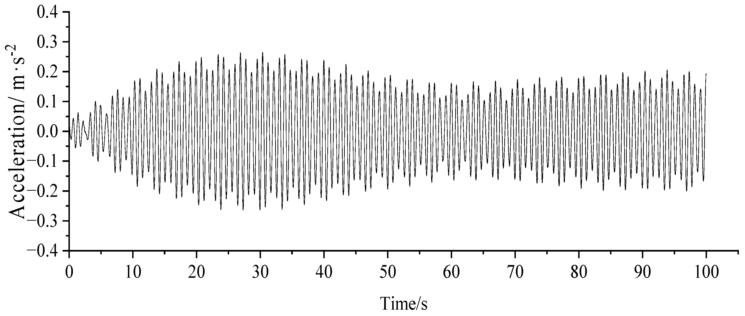
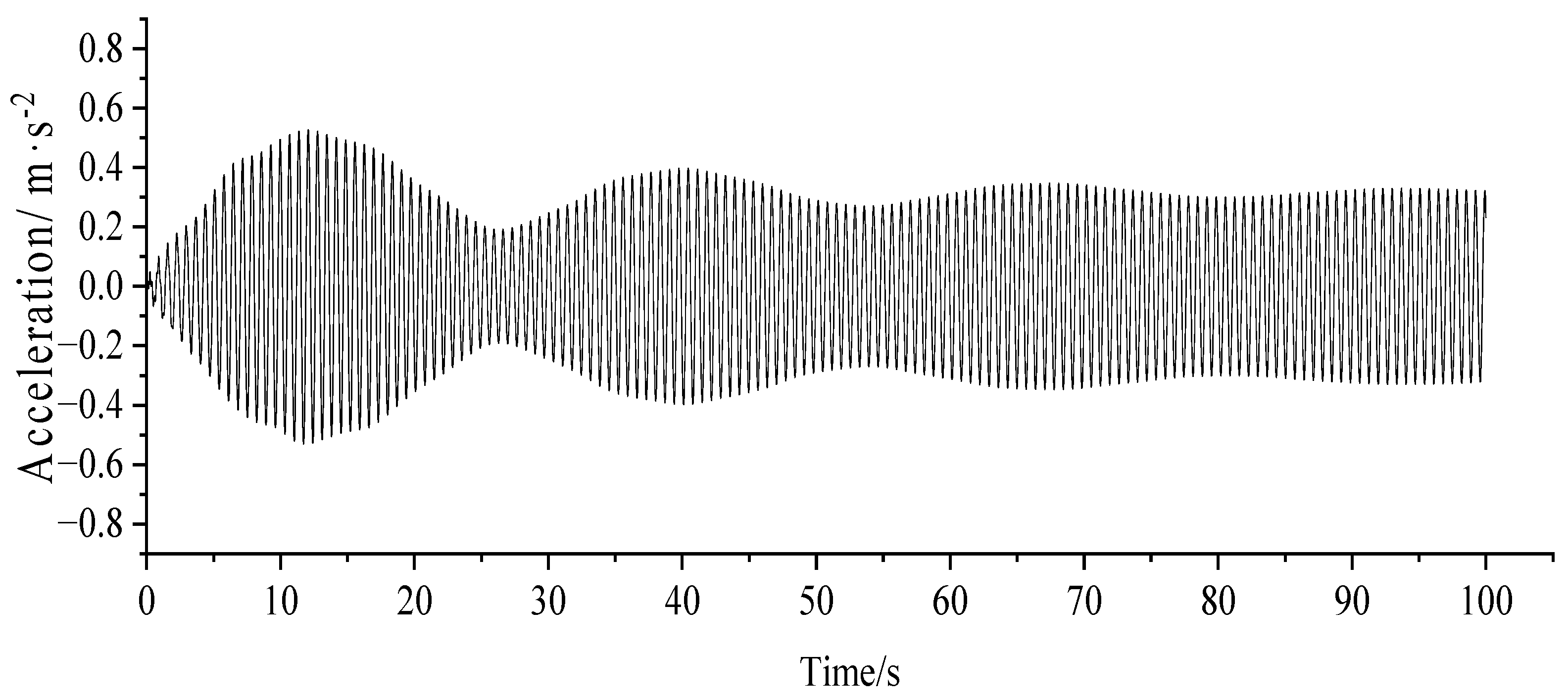
The maximum acceleration response analysis of the structure was carried out, and the acceleration time curve at u = 0.01–0.03 are indicated in Figure 5, Figure 6, Figure 7 and Figure 8.
The result shows that the setting of the TMD has a significant effect on the damping of the structure, and the larger the mass of the TMD, the better the damping effect; however there is no linear relationship between the mass of the TMD and the damping rate.
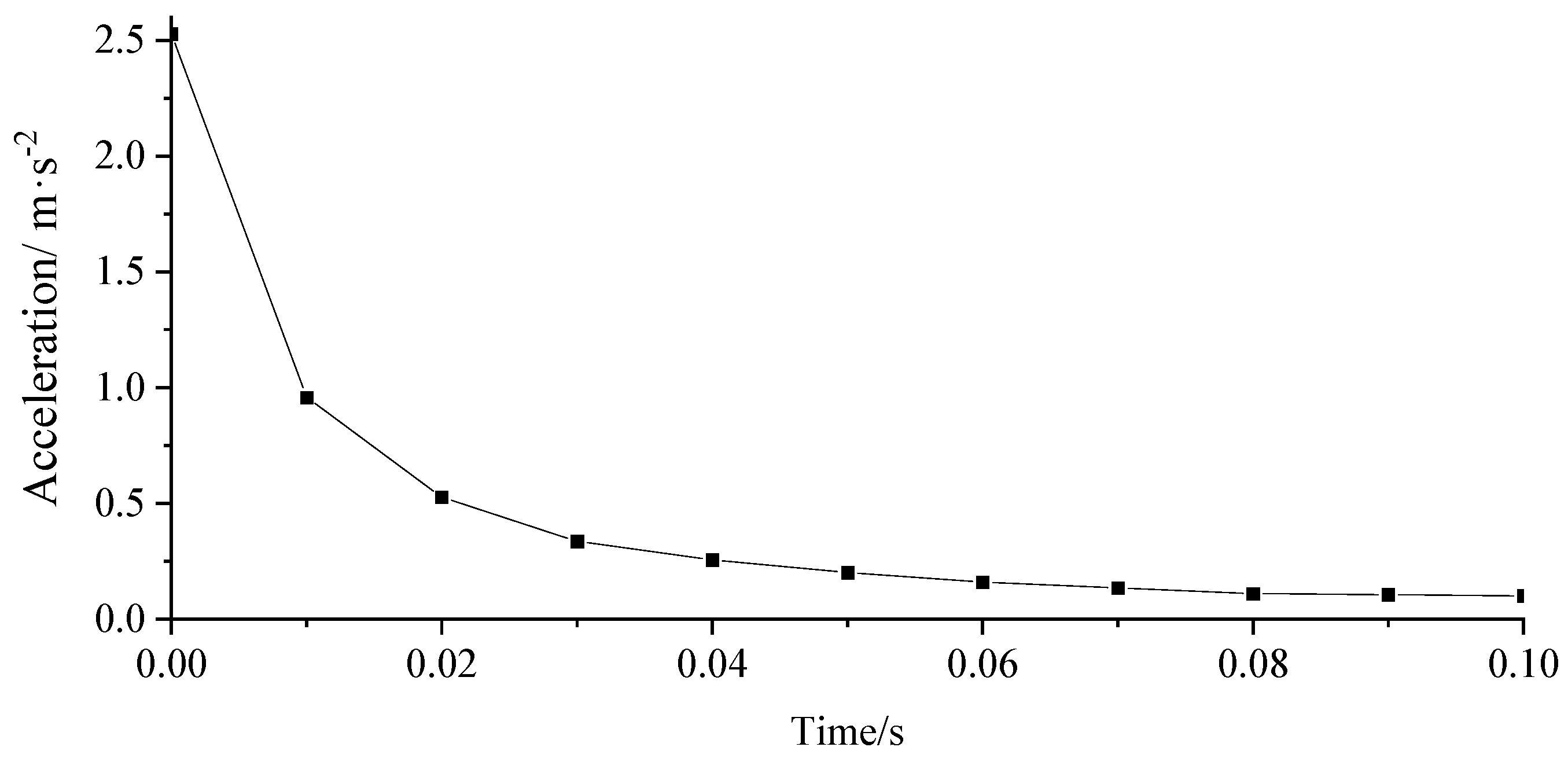
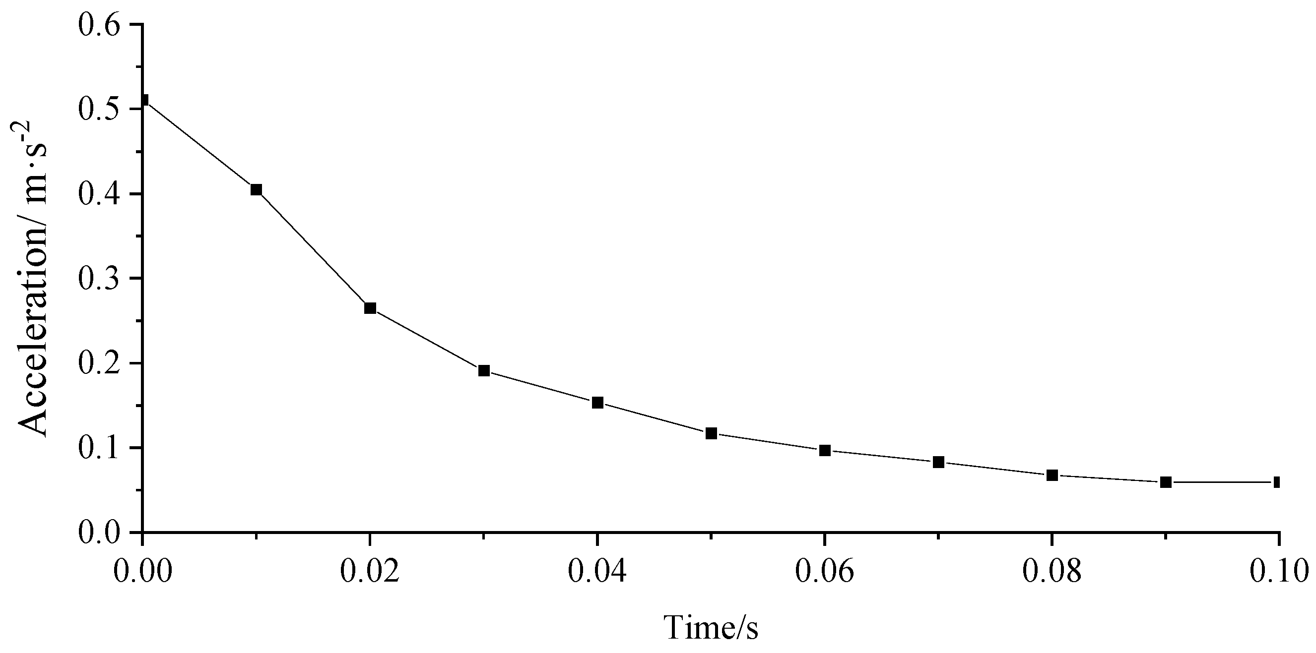
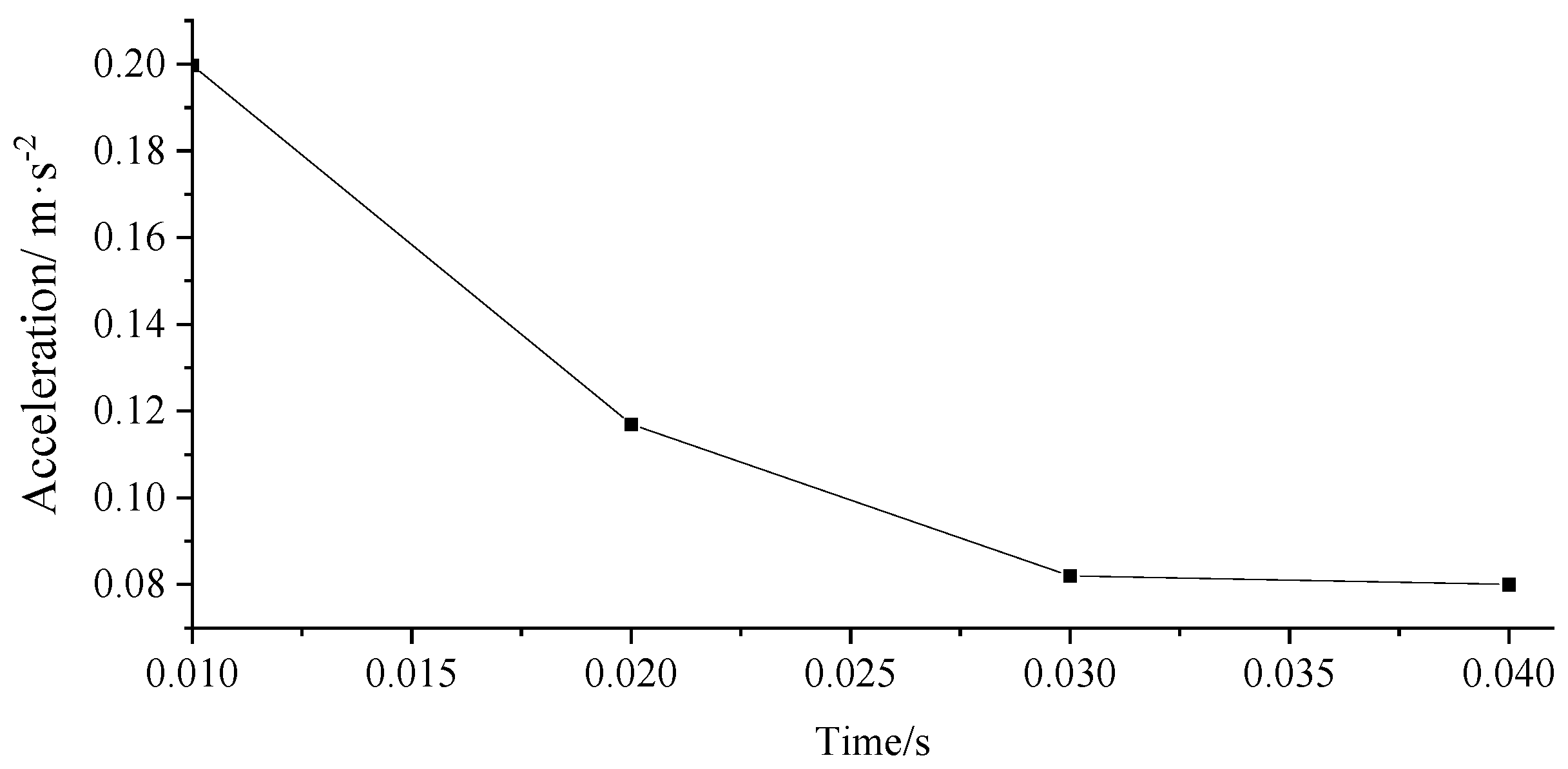
According to Figure 9, the damping efficiency was higher with the generalized mass ratio u taken as 0.01–0.03 in the vertical direction. When u exceeds 0.02, the maximum vertical acceleration is less than 0.5 m/s2, and the comfort level reaches the best level. When u continues to increase, the maximum vertical acceleration reduction rate slows down significantly. In Figure 10, with the increase of u, the maximum lateral acceleration reduction rate slowed down significantly. When u reaches 0.06, the maximum lateral acceleration is less than 0.1 m/s2, and the comfort level reaches the best level. Compared with the vertical direction, the control efficiency of the lateral acceleration of a large span pedestrian arch bridge is lower.
The first-order lateral vibration of the arch bridge is the coupling vibration of the bridge deck and arch ribs. Therefore, the lateral vibration of the arch ribs was not effectively suppressed with the TMD not being set on the arch ribs, and the vibration damping efficiency was poor.
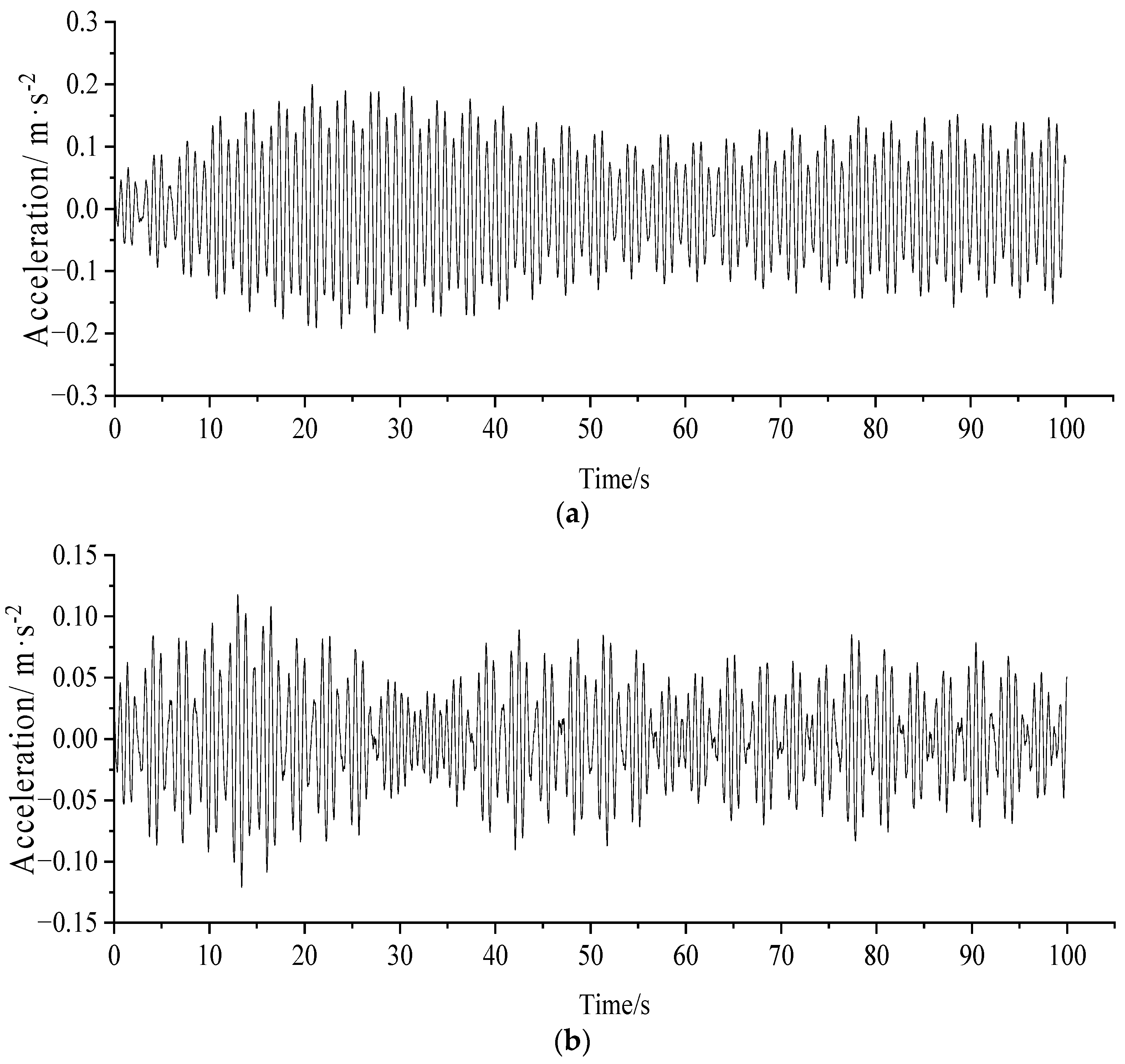
According to the first-order transverse vibration pattern of the structure, the transverse displacement of the arch rib occurred at the mid-span. The TMD was added to the arch rib at the mid-span position, and the acceleration times at the mid-span of the bridge deck were calculated for u equal to 0.01–0.04, respectively (as shown in Figure 11 and Figure 12).
From Figure 11 and Figure 12, when u is greater than 0.02, the maximum lateral acceleration is less than 0.1, and the comfort level achieves the best level. When the combined mass of the arch ribs and deck TMD equaled 2124 kg, the comfort level achieved the best level with the TMD setting only at the span of the bridge deck. In addition, corresponding to a TMD mass of 3043 kg, u needs to be greater than 0.6. Thus, it was found to be more effective in suppressing lateral vibrations with the TMD installed on both of the arch ribs and the bridge deck.

6. Conclusions

In this study, a spatial finite element model of a large-span pedestrian arch bridge was established to investigate the damping effect of different generalized mass ratios through time domain dynamic analysis and comparison of the damping effect of placing TMDs at different locations. This research can be used to guide the design of vibration damping for large-span pedestrian arch bridges. The following conclusions were obtained through the analysis:
(1)
Under the pedestrian load, the maximum lateral acceleration of the case bridge deck reached 0.511 m/s2 and the maximum vertical acceleration reached 2.528 m/s2, which exceeded the limits specified in EN03 and affected the comfort level of pedestrians. Setting the TMD on the bridge and adopting reasonably suitable TMD parameters, a better damping effect was obtained, by which the vertical acceleration was reduced to below 0.5 m/s2 and the lateral to below 0.1 m/s2, meeting the code requirements.
(2)
According to the analysis of the dynamic response of the structure without using the generalized mass ratio, for the large span pedestrian arch bridge, the vibration reduction efficiency was higher when the generalized mass ratio u was taken as 0.01–0.03.
(3)
Considering that the first-order lateral vibration of the arch bridge was the coupled vibration of the bridge deck and arch ribs, setting TMD at both of the arch ribs and the bridge deck was found to suppress better the transverse vibration.

Author Contributions

Methodology, J.L.; data curation, J.L.; formal analysis, J.L.; Software analysis, X.L.; supervision, X.L. All authors have read and agreed to the published version of the manuscript.

Funding

This research was funded by “Shaanxi Provincial Department of Science and Technology”, The project subcategories are “Shaanxi Provincial Science and Technology Plan Project Natural Science Basic Research Program (General Project), grant number 2020JM-234”.

Institutional Review Board Statement

Studies not involving humans or animals.

Informed Consent Statement

Not applicable.

Data Availability Statement

Data is contained within the article.

Acknowledgments

The authors would like to express their appreciation to Peijie Zhang for his supervision and revision which helped us immensely in improving the quality and clarity of our research.

Conflicts of Interest

The authors declare no conflict of interest.

References

  1. Bachmann, H. Case studies of structures with man-induced vibrations. J. Struct. Eng. ASCE 1992, 118, 631–647. [Google Scholar] [CrossRef]
  2. Nakamura, S.; Kawasaki, T. Lateral vibration of footbridges by synchronous walking. J. Constr. Steel Res. 2006, 62, 1148–1160. [Google Scholar] [CrossRef]
  3. Fujino, Y.; Pacheco, B.M.; Nakamura, S.-I.; Warnitchai, P. Synchronization of Human Walking Observed during Lateral Vibration of a Congested Pedestrian Bridge. Earthq. Eng. Struct. Dyn. 1993, 22, 741–758. [Google Scholar] [CrossRef]
  4. Brownjohn, J.M.W.; Fu, T.N. Vibration excitation and control of a pedestrian walkway by individuals and crowds. Shock. Vib. 2005, 12, 333–347. [Google Scholar] [CrossRef] [Green Version]
  5. Beijing Municipal Engineering Research Institute. CJJ 69-1995, Technical Specifications of Urban Pedestrian Overcrossing and Underpass; China Architecture and Building Press: Beijing, China, 1996. (In Chinese) [Google Scholar]
  6. BS 5400-3; Steel, Concrete and Composite Bridges. British Standers Institution: London, UK, 2000.
  7. EN 2004-2; Eurocode 4: Design of Composite Steel and Concrete Structures. European Committee for Standardization: Brussels, Belgium, 2005.
  8. BD 29/03; Design Manual for Roads and Bridges. The Highways Agency: London, UK, 2020.
  9. IS0 10137-2007; Bases for Design of Structures—Serviceability of Buildings and Walkways against Vibrations. International Standardization Organization: Geneva, Switzerland, 2007.
  10. Wang, D.; Tse, T.K.; Zhou, Y.; Li, Q. Structural performance and cost analysis of wind-induced vibration control schemes for a real super-tall building. Struct. Infrastruct. Eng. 2014, 11, 990–1011. [Google Scholar] [CrossRef]
  11. Xu, X.; Li, Z.; Liu, W.; Feng, D.; Li, X. Investigation of the wind-resistant performance of seismic viscous dampers on a cable-stayed bridge. Eng. Struct. 2017, 145, 283–292. [Google Scholar] [CrossRef]
  12. Kandemir, E.C.; Mazda, T.; Nurui, H.; Miyamoto, H. Seismic Retrofit of an Existing Steel Arch Bridge Using Viscous Damper. Procedia Eng. 2011, 14, 2301–2306. [Google Scholar] [CrossRef] [Green Version]
  13. Mokrani, B.; Zhui, T.; Alaluf, D.; Meng, F.H.; Preumont, A. Passive damping of suspension bridges using multi-degree of freedom tuned mass dampers. Eng. Struct. 2017, 153, 749–756. [Google Scholar] [CrossRef]
  14. Shinsuke, Y.; Tsutomu, U.; Tetsuya, N. Developing a new hysteretic type seismic damper (BRRP) for steel bridges. Eng. Struct. 2016, 124, 286–301. [Google Scholar]
  15. Preumont, A.; Voltan, M.; Sangiovanni, A.; Mokrani, B.; Alaluf, D. Active tendon control of suspension bridges. Smart Struct. Syst. 2016, 18, 31–52. [Google Scholar] [CrossRef] [Green Version]
  16. Crusells-Girona, M.; Aparicio, A.C. Active control implementation in cable-stayed bridges for quasi-static loading patterns. Eng. Struct. 2016, 118, 394–406. [Google Scholar] [CrossRef] [Green Version]
  17. Blekherman, A.N. Swaying of pedestrian bridges. J. Bridge Eng. ASCE 2005, 10, 142–150. [Google Scholar] [CrossRef]
  18. Bruno, L.; Venuti, F.; Nascé, V. Pedestrian-induced torsional vibrations of suspended footbridges: Proposal and evaluation of vibration countermeasures. Eng. Struct. 2012, 36, 228–238. [Google Scholar] [CrossRef]
  19. Caetano, E.; Cunha, A.; Magalhães, F.; Moutinho, C. Studies for controlling human-induced vibration of the Pedro e Inês footbridge, Portugal. Part 1: Assessment of dynamic behavior. Eng. Struct. 2010, 32, 1069–1081. [Google Scholar] [CrossRef]
  20. Caetano, E.; Cunha, A.; Magalhães, F.; Moutinho, C. Studies for controlling human-induced vibration of the Pedro e Ines footbridge, Portugal. Part 2: Implementation of tuned mass dampers. Eng. Struct. 2010, 32, 1082–1091. [Google Scholar] [CrossRef]
  21. Li, Q.; Fan, J.; Nie, J.; Li, Q.; Chen, Y. Crowd-induced random vibration of footbridge and vibration control using multiple tuned mass dampers. J. Sound Vib. 2010, 329, 4068–4092. [Google Scholar] [CrossRef]
  22. Van Nimmen, K.; Verbeke, P.; Lombaert, G.; De Roeck, G. Numerical and experimental evaluation of the dynamic performance of a footbridge with tuned mass dampers. J. Bridg. Eng. ASCE 2016, 21, C4016001. [Google Scholar] [CrossRef]
  23. Brock, J.E. Theory of the damped dynamic vibration absorber for inertial disturbances. J. Appl. Mech. 1949, 14, 86–92. [Google Scholar] [CrossRef]
  24. Dall’Asta, A.; Ragni, L.; Zona, A.; Nardini, L.; Salvatore, W. Design and experimental analysis of an externally prestressed steel and concrete footbridge equipped with vibration mitigation devices. J. Bridge Eng. 2016, 21, C5015001. [Google Scholar] [CrossRef]
  25. Chen, S.R.; Wu, J. Performance enhancement of bridge infrastructure systems: Long-span bridge, moving trucks and wind with tuned mass dampers. Eng. Struct. 2008, 30, 3316–3324. [Google Scholar] [CrossRef]
  26. Lin, C.C.; Wang, J.F.; Chen, B.L. Train-induced vibration control of high-speed railway bridges equipped with multiple tuned mass dampers. J. Bridge Eng. ASCE 2005, 10, 398–414. [Google Scholar] [CrossRef]
  27. Poovarodom, N.; Sopak, K.; Pennung, W. Application of non-linear multiple tuned mass dampers to suppress man-induced vibrations of a pedestrian bridge. Earthq. Eng. Struct. Dyn. 2003, 32, 1117–1131. [Google Scholar] [CrossRef]
  28. Song, Y. Comfort analysis and TMD vibration reduction design of long-span footbridge. Urban Roads Bridges Flood Control 2021, 7, 118–120+149+15–16. (In Chinese) [Google Scholar]
  29. Den, H.J.P. Mechanical Vibrations; Courier Corporation: Chelmsford, UK, 2011. [Google Scholar]
  30. Werkle, H.; Butz, R.; Tatar, R. Effectiveness of “detuned” TMD’s for beam-like footbridges. Adv. Struct. Eng. 2013, 16, 21–31. [Google Scholar] [CrossRef]
  31. Fan, J.S.; Chen, Y.; Nie, J.G. Optimum design of tuned mass damper for footbridge. Eng. Mech. 2012, 29, 133–140. (In Chinese) [Google Scholar]
  32. Andriacchi, T.P.; Ogle, J.A.; Galante, J.O. Walking speed as a basis for normal and abnormal gait measurements. J. Biomech. 1977, 10, 261–268. [Google Scholar] [CrossRef] [PubMed]
  33. Nakamura, S.I.; Kawasaki, T.; Katsuura, H.; Yokoyama, K. Experimental studies on lateral forces induced by pedestrians. J. Constr. Steel Res. 2007, 64, 247–252. [Google Scholar] [CrossRef]
  34. Ricciardelli, F.; Pizzimenti, A.D. Lateral walking-induced forces on footbridges. J. Bridge Eng. ASCE 2007, 12, 677–688. [Google Scholar] [CrossRef]
  35. Zoltowski, K.; Piotr, Z. Dynamic Analysis of Pedestrian Bridges with Fem and Cfd; Gdnask University of Technology: Gdańsk, Poland, 2005. [Google Scholar]
  36. Young, P. Improved Floor Vibration Prediction Methodologies; ARUP Vibration Seminar: London, UK, 2001. [Google Scholar]
  37. AASHTO GSDPB-2009; LRFD Guide specifications for the Design of Pedestrian Bridges. American Association of State Highway and Transportation Officials: Washington, DC, USA, 2009.
  38. FIB Bulletin 32; Guidelines for the Design of Footbridges. International Federation for Structural Concrete: Geneva, Switzerland, 2005.
  39. RFS2-CT-2007-00033; Design of Footbridges-Guidelines and Background Document. Research Found for Coal and Steel: Brussels, Belgium, 2007.
  40. Wu, Y.; Li, J.; Sun, Q. Study on human-induced vibration of a cable-stayed bridge without backstays located in abrupt valley. Adv. Struct. Eng. 2021, 24, 3101–3117. [Google Scholar] [CrossRef]
  41. Blanchard, J.; Davies, B.L.; Smith, J.W. Design criteria and analysis for dynamic loading of footbridges. In Proceedings of the DOE and DOT TRRL Symposium on Dynamic Behaviour of Bridge, Crowthorne, UK, 19 May 1977; pp. 90–106. [Google Scholar]
  42. Research Fund for Coal and Steel. HiVoSS: Design of Footbridges; Guideline EN03; Research Fund for Coal and Steel: Luxembourg, 2008. [Google Scholar]
  43. Soong, T.T.; Dargush, G.F. Passive Energy Dissipation Systems in Structural Engineering; John Wiley and Sons: Hoboken, NJ, USA, 1997. [Google Scholar]
Figure 1. FE model of the case bridge.
Applsci 13 08263 g001
Figure 2. Mode shapes of the case bridge. (a) First order vibration pattern, (b) second order vibration pattern, (c) third order vibration pattern, (d) fourth order vibration pattern.
Applsci 13 08263 g002
Figure 3. Time course of lateral acceleration of middle section.
Applsci 13 08263 g003
Figure 4. Time course of vertical acceleration of section at 1/4 L span.
Applsci 13 08263 g004
Figure 5. Time course of lateral acceleration of middle section. (u = 0.01).
Applsci 13 08263 g005
Figure 6. Time course of vertical acceleration of section at 1/4 L span. (u = 0.01).
Applsci 13 08263 g006
Figure 7. Time course of lateral acceleration of middle section. (u = 0.02).
Applsci 13 08263 g007
Figure 8. Time course of vertical acceleration of section at 1/4 L span. (u = 0.02).
Applsci 13 08263 g008
Figure 9. Maximum vertical acceleration in the vertical direction after TMD damping determined for different u.
Applsci 13 08263 g009
Figure 10. Maximum lateral acceleration in the vertical direction after TMD damping determined for different u.
Applsci 13 08263 g010
Figure 11. Maximum lateral acceleration response with additional TMD in the span of the arch rib. (a) u = 0.01 vertical maximum lateral acceleration, (b) u = 0.02 vertical maximum lateral acceleration.
Applsci 13 08263 g011
Figure 12. Maximum vertical lateral acceleration of the bridge deck after simultaneous installation of TMD on the arch ribs and deck system.
Applsci 13 08263 g012
Table 1. The first 10 order of frequency and related description of the case arch bridge.
Vibration TypeFrequency (Hz)Description
11.150896First-order lateral bending of bridge deck and arch ribs
21.427685First-order vertical bend of bridge deck + vertical bend of arch rib
31.446180Antisymmetric vertical bend of bridge deck + vertical bend of arch rib
41.854052Arch rib lateral antisymmetric side bend
52.499991Bridge deck and arch rib vertical bend
63.392810Bridge deck with arch rib second-order lateral bend
73.521042Bridge deck second-order lateral bend + arch rib third-order lateral bend
83.922015Bridge deck second-order vertical bend + arch rib second-order vertical bend
93.981197Bridge deck third-order vertical bend + arch rib second-order vertical bend
104.763216Bridge deck third-order vertical bend + arch rib third-order vertical bend
Table 2. Criteria for comfort evaluation of pedestrian bridges.
LevelDescriptionVertical Acceleration Limit (m/s2)Lateral Acceleration Limit (m/s2)
CL1Best<0.5<0.1
CL2Moderate0.5–10.1–0.3
CL3Poor1–2.50.3–0.8
CL4Unacceptable>2.5>0.8
Table 3. TMD physical parameters in vertical direction.
umTMD (kg)kTMD (N/m)c (m/s2)
0.01486.9139,400.32533.77
0.02973.8177,263.091487.59
0.031460.72113,655.182693.18
0.041947.63148,640.024086.77
0.052434.54182,277.835630.03
0.062921.44214,625.827296.39
0.073408.35245,738.349065.91
Table 4. TMD physical parameters in transverse direction.
umTMD (kg)kTMD (N/m)c (m/s2)
0.01507.2325,960.92442.23
0.021014.4750,908.761232.47
0.031521.7074,887.562231.29
0.042028.9397,939.123385.87
0.052536.16120,103.114664.47
0.063043.40141,417.256045.04
0.073550.63161,917.347511.08
Disclaimer/Publisher’s Note: The statements, opinions and data contained in all publications are solely those of the individual author(s) and contributor(s) and not of MDPI and/or the editor(s). MDPI and/or the editor(s) disclaim responsibility for any injury to people or property resulting from any ideas, methods, instructions or products referred to in the content.