Article

Study of the Tensile and Bonding Properties between Cement-Based Grout Materials and High-Strength Bolts

1
School of Civil Engineering, Central South University, 22 Shaoshan Road, Changsha 410075, China
2
National Engineering Research Center for High Speed Railway Construction, Changsha 410075, China
3
China Railway Group Ltd., 69 Fuxing Road, Beijing 100039, China
4
School of Physical and Technology, YiLi Normal University, 448 Jiefang West Road, Yining 835000, China
5
School of Civil Engineering, Central South University of Forestry and Technology, 498 Shaoshan Road, Changsha 410004, China
*
Author to whom correspondence should be addressed.
Appl. Sci. 2023, 13(14), 8269; https://doi.org/10.3390/app13148269
Submission received: 20 June 2023 / Revised: 3 July 2023 / Accepted: 11 July 2023 / Published: 17 July 2023
(This article belongs to the Section Civil Engineering)

Abstract

:
This study investigated the tensile and bonding properties between cement-based grouting materials (CBGM) and high-strength bolts. The associated failure mechanism, load-slip curve, ultimate pull-out load and bond stress were also studied. The effects of anchorage length and square steel tube restraint on the bonding properties were explored on the basis of 24 specimens used in central pull-out testing, and a bond stress–slip constitutive relationship model between high-strength bolts and CBGM was proposed. The results indicate that with the increase in the anchorage length of high-strength bolts, the failure modes of specimens can be divided into three types: the fracture failure of high-strength bolt that occurred when the anchorage lengths ranged from 18 d to 31 d, the specimens that experienced splitting failure with the constraint of square steel tube when the anchorage length was less than 15 d and the high-strength bolt that experienced pull-out failure without the constraint of square steel tubes. When the high-strength bolt experiences tensile failure, the ultimate pull-out load remains constant and the bond stress decreases as the anchorage length of high-strength bolts increases. Due to the lateral constrained effect of the square steel tube, the CBGM embodies a three-dimensional stress state, which can delay the generation and development of internal cracks and enhance the bond strength. A calculation formula was proposed to determine the bond strength between high-strength bolt and CBGM, and a constitutive model of the bond stress–slip constitutive relationship was modeled.

1. Introduction

Cement-based grouting materials (CBGM) are composed of cementitious materials and high-strength fine aggregates, which possess excellent performances, including high fluidity, micro-expansion, anti-segregation, and early high strength. Therefore, the development and usage of the CBGM has greatly increased since the invention of CBGM [1]. They are mainly used for the grouting of equipment installation, foundation bolt anchoring column foundation and post-tensioned pre-fabricated specimens. Furthermore, they are also used in emergency rescue and disaster relief operations. Moreover, the most common application is that involving the bonding property between steel and CBGM [2]. However, the theoretical analysis and bonding mechanism between steel bars and CBGM are rarely reported. In order to promote the application of CBGM in engineering structures, it is important to propose a bond-strength calculation formula and establish the bond stress–slip formula between high-strength bolts and CBGM via investigation into the tensile and bonding properties.
At present, the corresponding achievements of the tensile and bonding properties between steel bars and CBGM are quite advanced. Hayashi et al. [3] studied the relationship between the bond strength and steel bar slippage under the cyclic load. The bond strength calculation expression was fitted based on the mechanical properties of the CBGM, as well as the diameters and anchorage lengths of the steel bars. Drawin et al. [4] considered the effects of the hole preparation method, grout type, hole diameter, steel bar size, anchorage length, cover, steel bar deformation pattern, bar surface condition, orientation of the installed bar and concrete strength on the bond strength between steel bar and CBGM. Their results showed that the bond strength was positively correlated with the steel bar diameter and anchorage length, as well as the thickness of the concrete protective layer, but was independent of the hole size and the opening method. These results indicated that many factors affect the bond strength. Raynor et al. [5] investigated the bonding property between steel bars and CBGM under the repeated loads with the action of square steel tube limited CBGM, and they also analyzed the constitutive relationship between local bond stress and slippage. Moosavi et al. [6] discussed the influence of confining pressure on the bonding property between steel bar and CBGM. Their results indicated that there existed a non-linear relationship between the confining pressure and the bonding property, while a radial deformation formula of steel bar could be expressed by confining pressure through experimental analysis. Alisa et al. [7] examined the influence of square steel tubes with different inner and outer diameters, as well as different anchorage lengths of steel bars, on the bonding property under the action of square steel tubes through a monotonous tensile test. Hosseini et al. [8,9] investigated the bond anchorage properties influenced by different spacings of stirrup and spiral stirrup. According to the experiment, they obtained the corresponding stirrup spacing when the steel bar had minimum slippage, and the bonding property obtained from the beam test was lower than that obtained via center pull-out testing. Ling et al. [10] studied the bearing capacity of the steel bar affected by different dimensions of square steel tubes through a monotonic tensile test. Zhou et al. [11] found that the bond–slip response was influenced by the anchorage length and the ratio of the steel tube diameter to steel bar diameter, and the constitutive model of non-linear bond stress-slip was devised. Li et al. [12] performed the central pull-out test on 40 specimens, and they investigated the bond–slip performance between steel bar and normal concrete (NC) and steel fiber-reinforced concrete (SFRC) at high temperature. Their results showed that as the temperature increased, the bond strength decreased. Wu [13] analyzed the bonding property between the steel bar and the CBGM affected by CBGM strength, surface shape, diameter, anchorage lengths of steel bars and stirrup length and spacing through central pull-out testing. Moreover, it was found that the bonding property between the steel bar and CBGM was significantly better than that of the steel bar and concrete by comparing the result to the archetypal bond strength formulas. Yuan et al. [14] investigated the effect of bond lengths on the bond behavior between basalt fiber-reinforced polymer (BFRP) sheets and concrete, and the results showed that the failure load between the BFRP sheets and concrete increased in correlation with the increase in the bond length when the bond length was not increased beyond the effective bond length. Hu et al. [15] analyzed the bond properties of the specimens with different concrete ages and strength grades, and empirical bond stress–slip models of deformed steel bars in concrete during construction under reversed cyclic loading were proposed. Based on the above-mentioned existing achievements, we can conclude that most of the existing studies focused on the influence of concrete, CBGM, steel tube restraint and steel bars on the bonding property. High-strength bolts have the advantage of simple construction, good mechanical performance, removable, fatigue resistance, and not being loose under dynamic load; thus, the application of high-strength bolts in engineering is becoming increasingly common. With the increasing application of CBGM and high-strength bolts in engineering structures, it is important to investigate the bonding property between high-strength bolts and CBGM [16].
At present, the common experimental methods regarding the bonding property include the central pulling test, central compression test, beam test and beam end test, etc. At the same time, the plate and column tests are occasionally used [17,18,19]. Moreover, the center pulling test has the advantages of ease of fabrication, low cost, convenient loading, and ease of obtaining experimental data; therefore, it is recommended by GB/T 50152-2012 for use in engineering applications [20].
In this study, the central pull-out tests used for 24 specimens composed of pre-cast concrete and the high-strength bolt connected by the CBGM in a reserve hole or square steel tube were carried out. The objective of this study is to investigate the influence of the bolt anchorage lengths and steel tube restraint on the ultimate load, failure mode and bonding property of experimental specimens. Moreover, a formula for calculating the bond strength between high-strength bolts and CBGM was proposed, and a bond–slip constitutive model was created.

2. Theoretical Analysis

2.1. Bonding Mechanism

Bond force refers to the shear force that occurs along the contact surface between a steel bar and concrete. The bond force between bolt and CBGM is mainly composed of chemical bonding force, frictional force and mechanical bite force. The chemical bonding force derives from the penetration of cement paste into the oxide layer on a bolt’s surface during pouring, as well as the hardening of hydration of cement minerals during curing. The magnitude of chemical bonding force depends on the properties of the cement and the roughness of the bolt’s surface. The frictional force is generated by the CBGM shrinking and holding the bolt tightly, the occurrence of which depends on the CBGM’s shrinkage degree and the contact surface’s roughness. The mechanical bite force is formed via the mechanical bite effect between the bolt’s uneven surface and the CBGM. Among these three types of bonding forces, the chemical bonding force is generally very small. The frictional force of plain bolts is the main component of the bonding force, as it is the mechanical biting force for deformed bolts. The corresponding sliding process between the bolt and the CBGM can be viewed as the weakening and damage process of the chemical bonding force. After slippage, the bond force is mainly composed of frictional force. The specimens were composed of pre-cast concrete and high-strength bolts connected by CBGM in the square steel tube, and the confinement was effective in enhancing the bond and anchorage between reinforcement bars and CBGM [21]. The strain between the surface concrete and CBGM were changed by the bolt’s pulling-out forms—that is, in the ascending section of the displacement–load curve, the surface of the specimen was subjected to tensile strain, and in the descending section, the strain gradually changed from tensile strain to compressive strain between the center and the edge. Due to the restrictive effect of the square steel tube on the CBGM, the ductility of the CBGM and the tensile stress of the bolt improved when the bolt pulled out from CBGM.

2.2. Failure Mode and Force Analysis

The degree of influence of factors on the mechanical properties, which range from most significant to least significant, are as follows: bolt yield stress, diameter and surface shape. The failure modes of the specimens can be divided into three main types:
(1)
Bolt pull-out failure. This failure mode occurs when the tensile stress of the bolt is higher than the bond strength between the bolt and the CBGM, resulting in the bolt pulling out of the CBGM before reaching tensile stress. The mode of destruction is shown in Figure 1a.
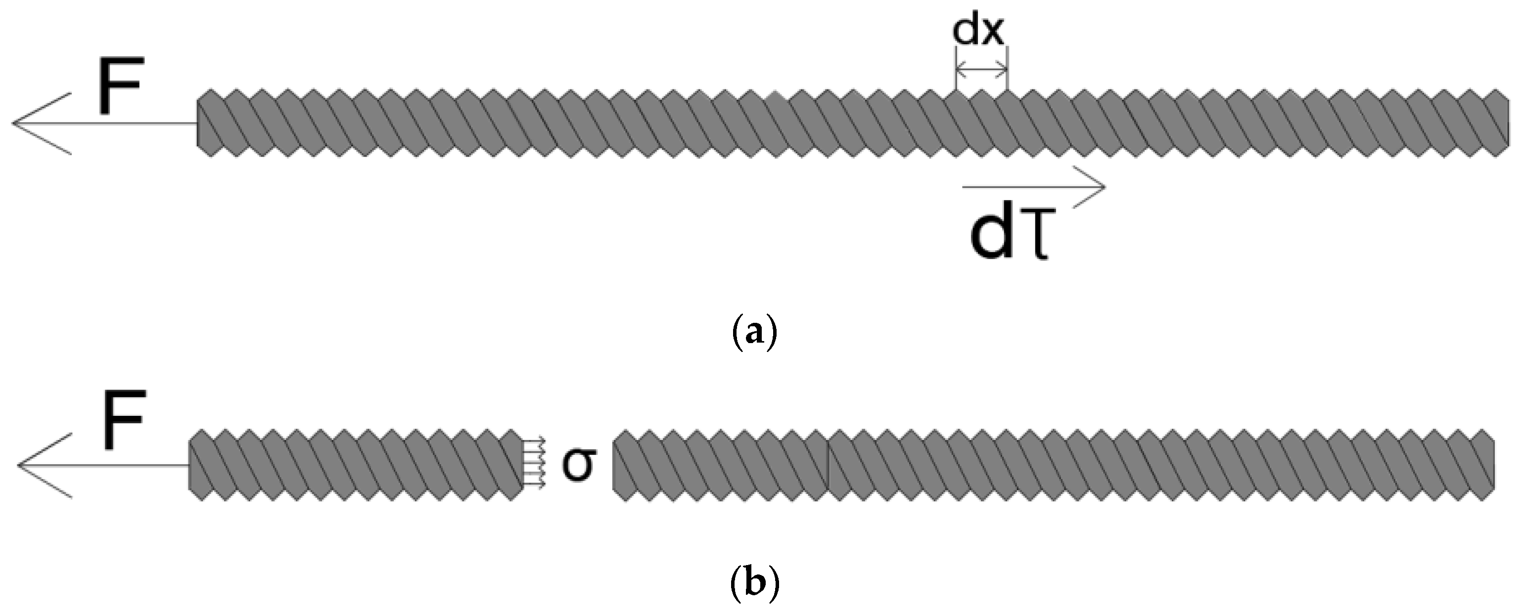
Using the dx micro-terminus, if the bolt pulls out from the CBGM or splitting/shear failure occurs, the force of the bolt appears as shown in Figure 2a, and the force relationship is written as follows:
F > 0 l a π d τ d x
where F is the bolt pulling force (kN), d is the bolt diameter (mm), τ is the bond stress between the bolt and CBGM (MPa) and la is the anchorage length of the bolt (mm).
Assuming that the bond stress is evenly distributed along the bolt, Equation (1) can be expressed as follows:
F > π d l a τ
(2)
Bolt fracture failure. The bond strength between the bolt and the CBGM is higher than the tensile stress of the bolt when the bolt stress grade is lower or the stress grade of the CBGM is higher. Therefore, the bolt stress reaches tensile strength before pulling out, which results in the bolt fracturing and being destroyed. The mode of destruction is shown in Figure 1b.
If the bolt fractures, the force of the bolt appears as shown in Figure 2b, and the force relationship can be calculated as follows:
F > 0 S σ dA
where S is the area of the bolt section (mm2), while σ is the stress from the bolt section (MPa).
These values can be obtained via the following formula:
F > σ S
(3)
Specimen splitting failure or shear failure. The protruding transverse ribs on the bolt surface produce an oblique extrusion force on the CBGM, which can be divided into the axial component force along the bolt surface and the radial component force. The axial component force makes the CBGM subject to circumferential tensile force, and the radial component force causes longitudinal cracks in the CBGM with the increase in load. The CBGM will be split and broken if the CBGM is not restrained by concrete and circumferential hoops. Conversely, the protruding transverse ribs on the bolt surface will crush and shear the CBGM. The mode of destruction is shown in Figure 1c.
If the specimen splitting failure or shear failure occur, the bolt pulling force will be the same as bond strength between the bolt and the CBGM. The force relationship is written as follows:
F = π d l a τ

3. Experimental Process

3.1. Material Parameter and Mechanical Properties

(1)
Material properties of CBGM
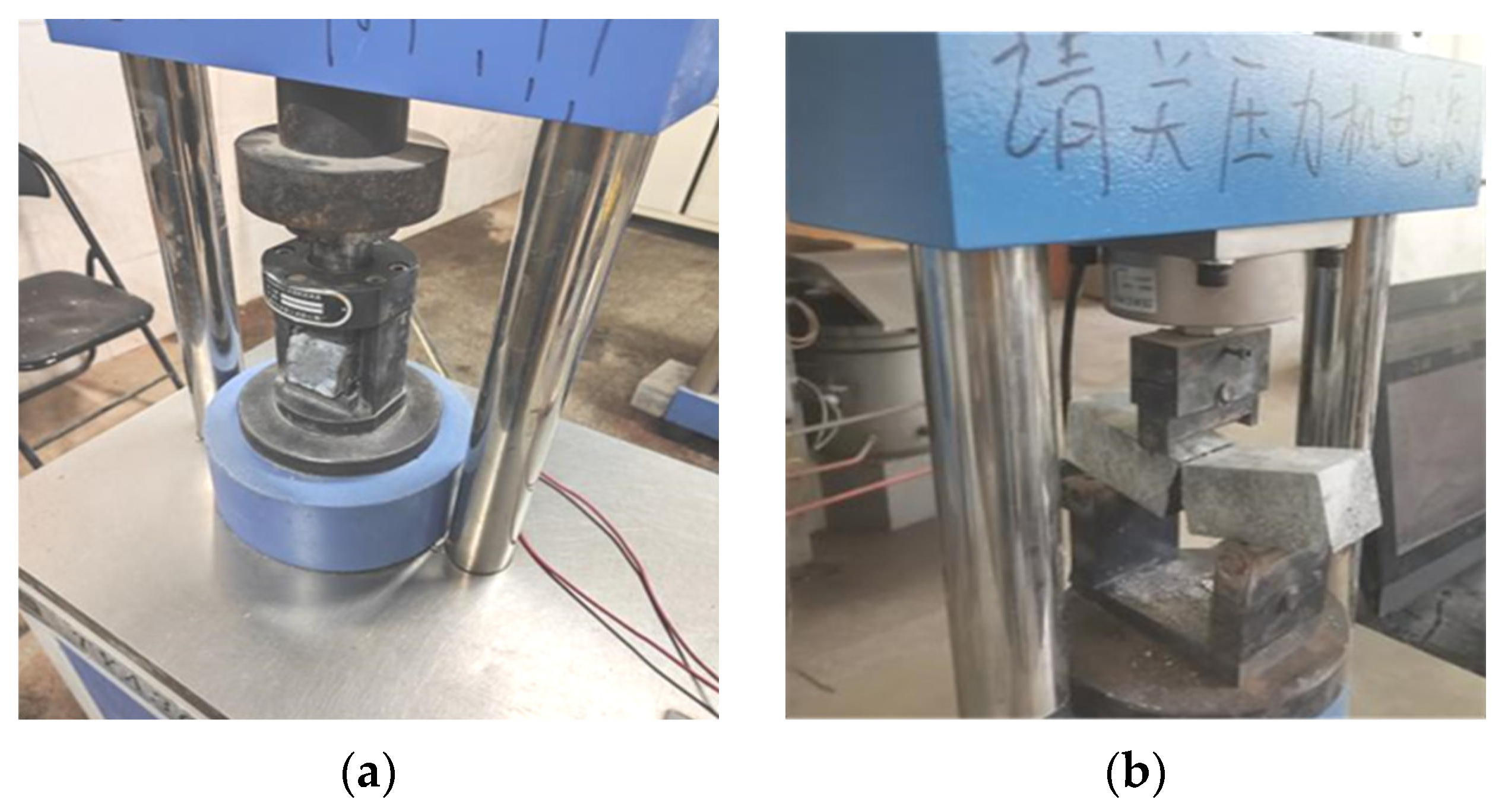
The CBGM needed a water to cement ratio of 0.136:1. According to the relevant provisions of GB/T 17671-2021 [22], six prismatic specimens of 40 mm × 40 mm × 160 mm were casted and cured for 28 d under the same conditions. Next, the CBGMs underwent testing was used to determine their flexural and compressive strengths. The three-point bending force control method was adopted to the load, and the flexural load was applied at a rate of 50 N/s. The compressive load was applied at a rate of 2.4 kN/s. The dimension of the two machine supports was slightly wider than that of the specimen, and the pressure head was equal to that of the specimen. The test procedure involved placing the specimen with measurements of 40 mm × 40 mm × 160 mm onto the testing machine, and a flexural load was applied at the middle of the specimen. Following the flexural test, the specimen was divided into two halves. Each part of the specimen was then subjected to a compressive strength test on the testing machine. This approach enabled the measurement of flexural and compressive strengths simultaneously, ensuring the accuracy of the test results. The flexural and compressive strengths of the specimens were averaged to obtain representative values. The testing process is shown in Figure 3, and the corresponding parameters of CBGM are shown in Table 1.
(2)
Concrete properties
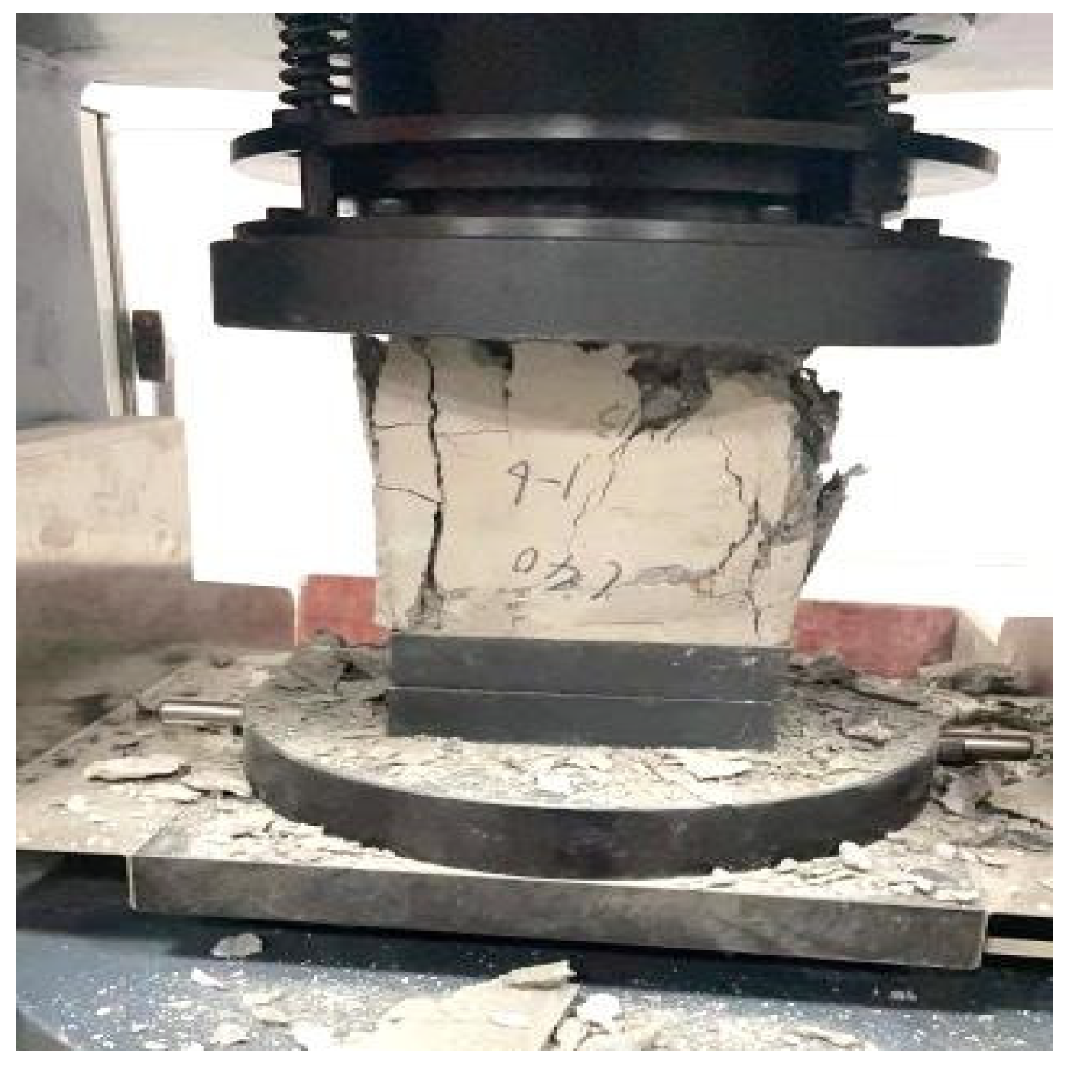
C40 concrete was investigated in this experiment. The P·O 42.5 Portland cement was used in this experiment, which was provided by Hunan Shaofeng Co. Ltd., Zhuzhou, China. River sand samples with fineness moduli of 2.7 were used as fine aggregates, and continuous grading limestone gravel samples with grain sizes of 5~20 mm were used as coarse aggregates. Aggregates constituted 75% of the concrete, with coarse aggregates accounting for 40% and fine aggregates accounting for 35%. Six concrete specimens of 150 mm × 150 mm × 150 mm were cast simultaneously using the concrete foundation platform and cured at a temperature of (20 ± 2) °C and with relative humidity above 95% for 28 d according to GB 50010-2010 [23] and BS EN 1992-1-1 [24]. The loading speed of the concrete axial compression experiment was 0.6 MPa/s according to GB/T 50081-2019 [25]. The compressive strengths of the concrete specimens cured for 28 d were tested, as shown in Figure 4. The compressive strength of concrete is shown in Table 2.
(3)
Bolt properties
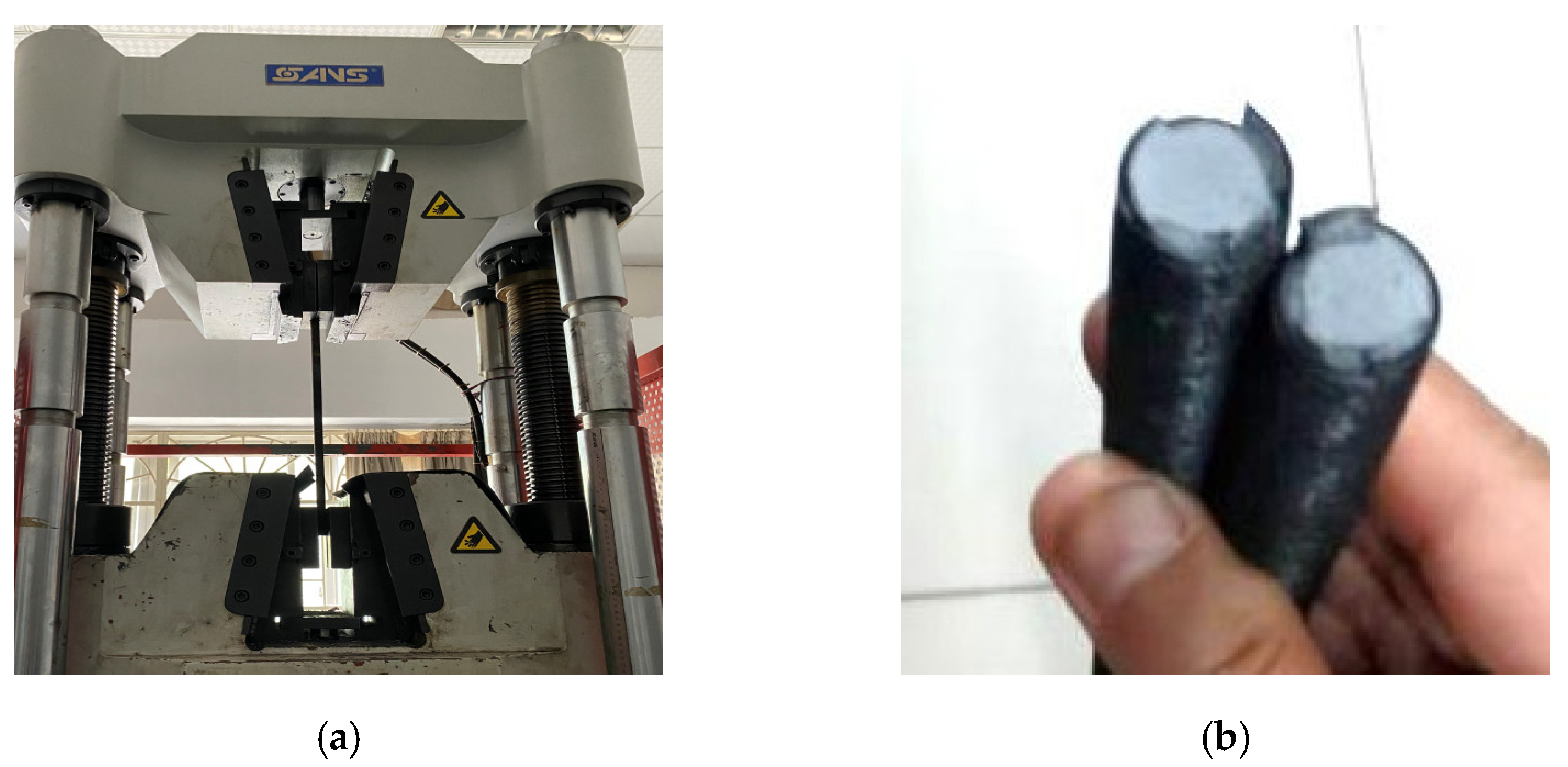
There were 24 grade 10.9 threaded bolts with nominal diameters of 16 mm used in this study. According to GB/T 228.1-2021 [26], three grade 10.9 threaded bolts with nominal diameters of 16 mm and active-area lengths of 500 mm were used to test the mechanical properties, and the loading rate was 8 MPa/s. The bolt was securely clamped using the chuck of the universal testing machine, and the yield and limit strengths were analyzed and tested. The bond strength test is shown in Figure 5, and the test results are listed in Table 3.

3.2. Preparation and Curing of Specimens

(1)
Design of specimens
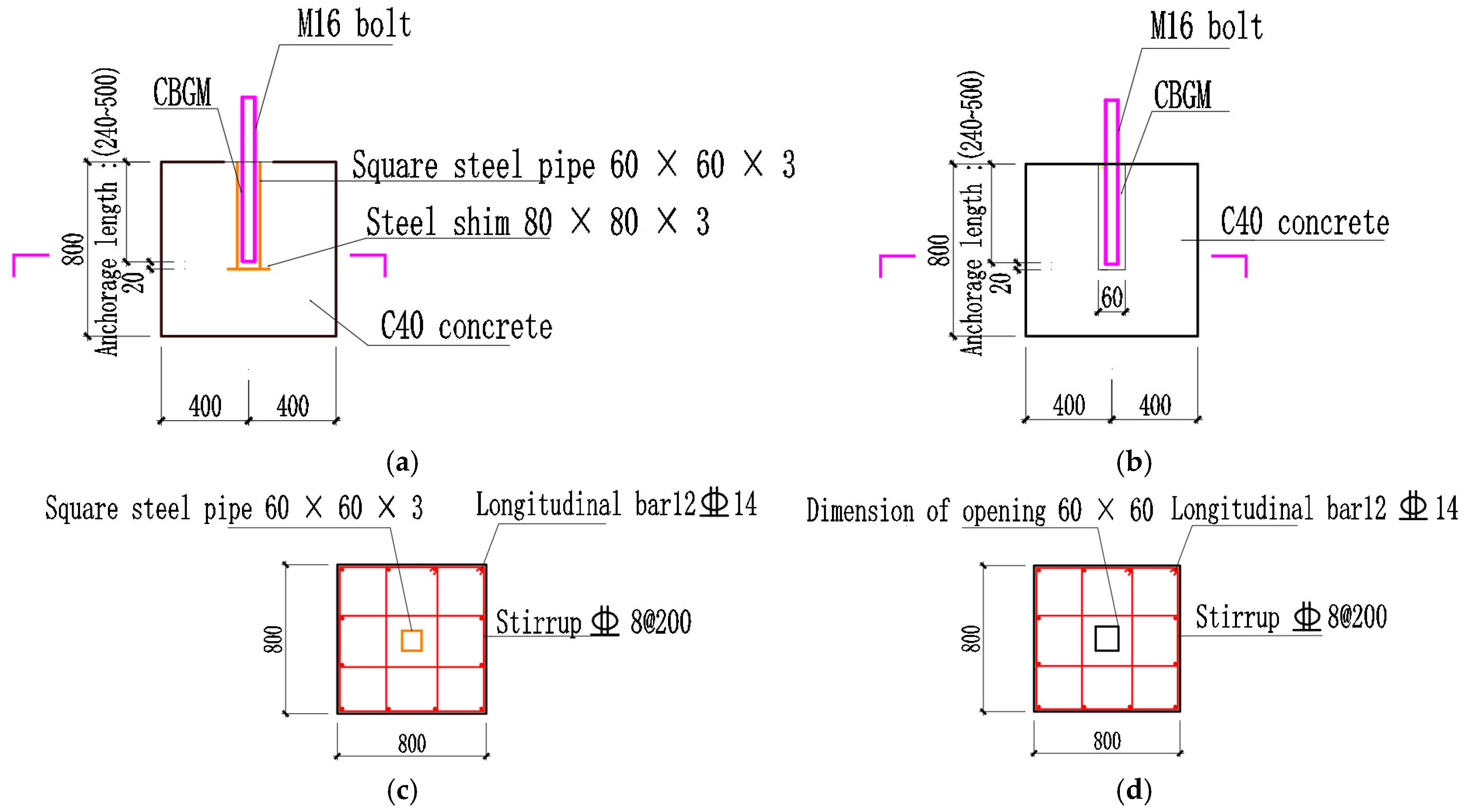
The experiment was carried out according to the relevant provisions of GB/T 50152-2012 [20]. The grade 10.9 threaded bolts with nominal diameters of 16 mm were used to perform the mechanical property test, and the choice of the bolt was considered based on the practical application of the engineering and structural requirements of the new connection method. The cubic concrete foundation platform with a side length of 800 mm was made of C40 concrete, and the steel bars in the concrete were configured according to the construction requirements. The CBGM was wrapped by the square steel tube with a side length of 60 mm in LB-A, and the CBGM in LB-B was wrapped by the reserving grouting hole with a side length of 60 mm in the concrete. There were four different anchorage lengths—240 mm, 300 mm, 400 mm, and 500 mm—in these two experimental designs. The depth of square steel tube and reserved grouting holes were the same as the anchorage lengths of high-strength bolts. Among them, each structural form had three identical specimens. The detailed geometric parameters of the specimens are shown in Table 4, and the specific structural designs are shown in Figure 6.
(2)
Preparation of specimens
The grouting hole and the square steel tube were reserved in their designated positions according to the requirements of the experimental design, and the steel bar was configured according to the constructional requirements when the concrete foundation platform was cast. After 28 d, the bolt with the rebar strain gauge was inserted into the reserved hole or the square steel tube at the designed anchorage lengths. Next, the CBGM was cast into the reserved grouting hole or the square steel tube. Lastly, the specimens were cured again for 28 d. The casting process used for the specimens is shown in Figure 7.
(3)
Experimental loading device
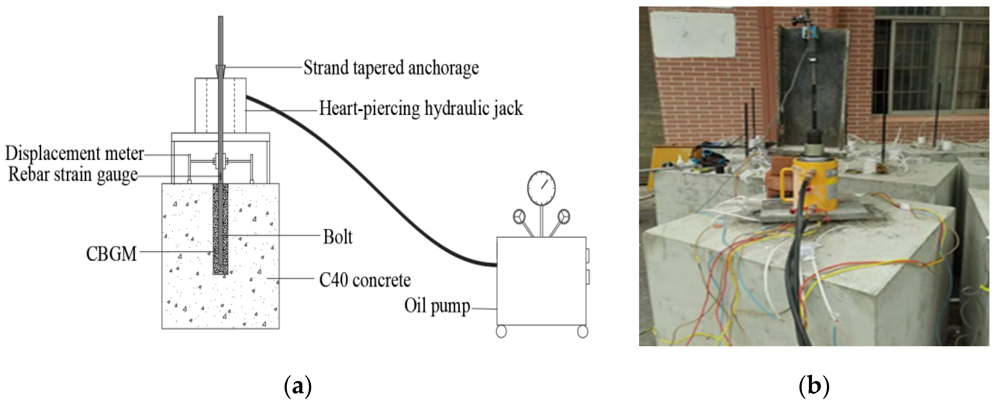
The heart-piercing hydraulic jack that we chose had a maximum load capacity of 1000 kN, a hole diameter of 55 mm and a maximum extension of 100 mm. According to the GB/T 50152-2012 [20], the loading rate of the pull-out testing experiment was controlled using the following formula:
V F = 0.03 d 2
where VF is the loading rate (kN/min).
The loading rate used to test the specimens was 0.5 kN/s, and the loading method adopted hierarchical loading, with the level increasing by 5 kN per stage. The corresponding data of the displacement meter and the rebar strain gauge of the high-strength bolt were recorded after loading for 10 min, and the next level loading was then proceeded. The loading device diagram is shown in Figure 8.

4. Results and Discussion

4.1. Experimental Phenomena and Failure Characteristics

According to the above-outlined loading method, 36 specimens were loaded until damage to the concrete and the CBGM, as well as the fracture of bolt or pull out of the CBGM, occurred. The failure modes of pull-out testing are shown in Table 5.
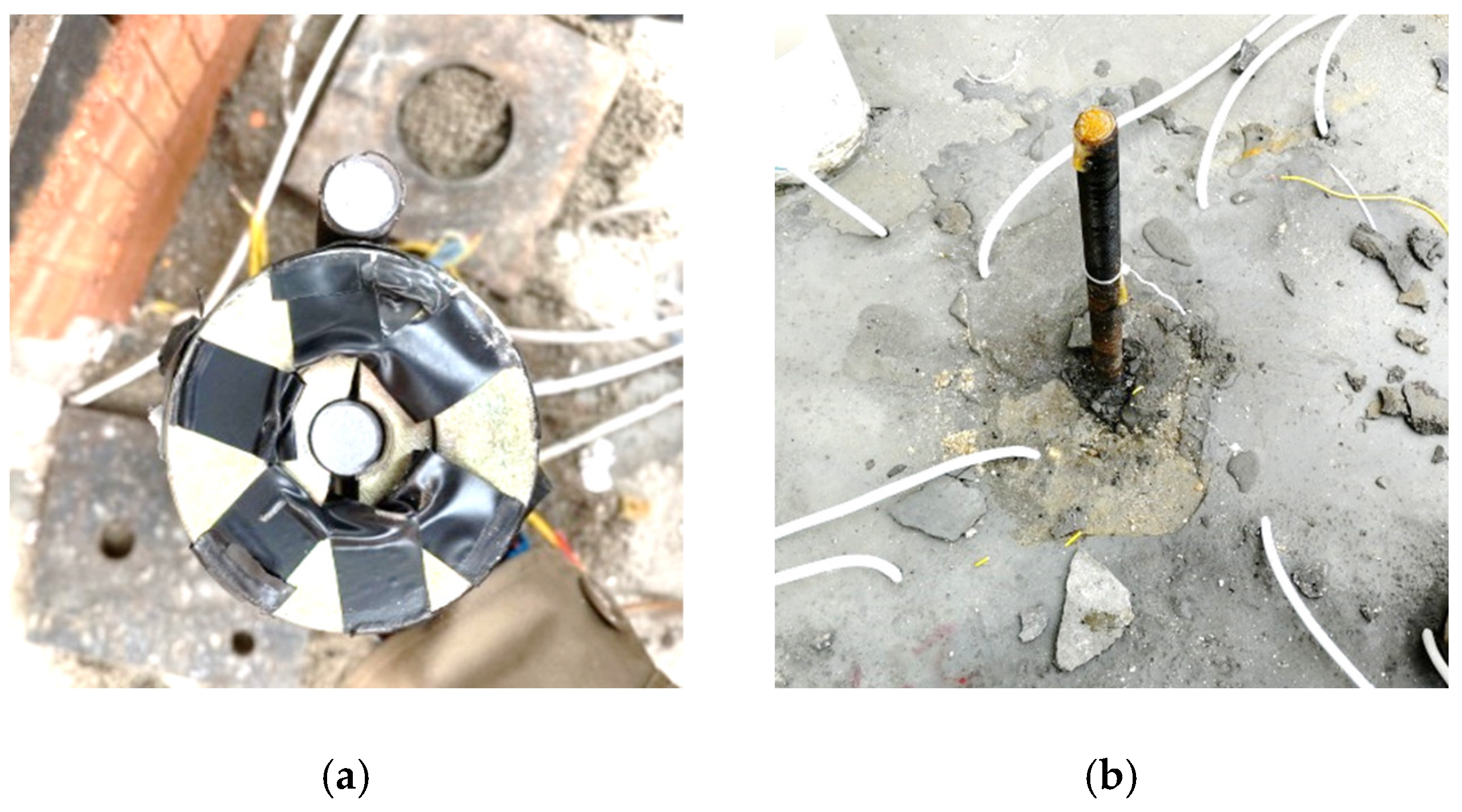
As can be seen from Table 5, in LB-A, the high-strength bolts with anchorage lengths of more than 300 mm were concentratedly broken at the strand-tapered anchorage, and at these locations, the high-strength bolt necking phenomenon also occurred, though there were no damage to the concrete and the CBGM. During the initial loading stage of the specimens, concrete, CBGM and high-strength bolt did not significantly change, though the high-strength bolt was stretched with extremely small changes caused by the heart-piercing hydraulic jack, and a significant necking phenomenon happened due to the increase in load. Finally, the high-strength bolt instantly fractured and created a broken acoustic emission when the load rose beyond a certain extent. When the high-strength bolt had an anchorage length of less than 300 mm in LB-A, it pulled out of the CBGM, and it did not experience fracturing or necking. During the loading process, the concrete and the CBGM did not experience significant changes or damage, though the high-strength bolts pulled out with a dull loud band when the load increased beyond a certain extent. The forms of destruction are shown in Figure 9.
In LB-B, it was observed that the high-strength bolts with anchorage lengths of more than 300 mm were broken on the outside of CBGM. The location at which the high-strength bolt necked and fractured was concentrated at the strand-tapered anchorage, though the concrete and CBGM remained undamaged. When the high-strength bolts had anchorage lengths of less than 300 mm, the bolts slipped but did not fracture, and there were a large number of cracks on the concrete and CBGM surface, with some fragments falling off. The failure modes are shown in Figure 10.
The experimental phenomenon showed that when the high-strength bolts had anchorage lengths of more than 18 d, the bolt bond–slip failure and splitting or shear failures of the specimens could not be observed during the process of high-strength bolt pulling. The reason for this outcome may be that the CBGM was extruded when the load applied to the bolt reached the ultimate tensile load; thus, the CBGM tended to expand outward. However, the internal hoop and square steel tube had a hoop effect in the core area of the CBGM. Therefore, the bonding force between the high-strength bolt and the CBGM effectively prevented the bolt from slipping. When the anchorage length was 15 d, the concrete and the CBGM in LB-A had little to no damage compared to LB-B, which showed that the existence of the square steel tube could inhibit the occurrence and development of crack in concrete and CBGM.

4.2. Results of Bolts Pull-Out Testing

(1)
Load–displacement relationship
In the pull-out testing stage, the load and bolt displacement were measured during the loading process. The load value was imposed by the heart-piercing hydraulic jack, and the bolt displacement was calculated by subtracting the deformation value of the bolt measured on the rebar strain gauge from the value of the displacement meter. The average value of three specimens was taken for each group to obtain the load–displacement curves in the pull-out testing stage, as shown in Figure 11.
The following outcomes can be seen in the above load–displacement curves:
When the anchorage length of the bolt was 15 d, the maximum load applied to the bolts of LB-A and LB-B reached 163.5 kN and 128.34 kN, respectively. Both LB-A and LB-B failed to reach the ultimate load of the high-strength bolts, while LB-A experienced bond–slip failure and LB-B exhibited splitting failure. However, the ultimate bond load between the bolt and the CBGM increased in LB-A due to the constraint of the square steel tube. When the anchorage lengths of the bolts were more than 18 d, both experimental designs showed a significant yield stage on the load–displacement curve. The slip changed less noticeably when the load was increased before the bolts yielded, while the slip increased significantly until the load applied to the bolts reached the limit load, before fracturing when the load exceeded the yield load.
Based on the analysis of the load–displacement curves, it can be concluded that the load–displacement curves for bolt fracture failure are similar, regardless of the bolt anchorage lengths. The load is transmitted quickly to the bolt’s bottom during the loading process, which prevents the bolt from slipping if it has a small anchorage length. On the other hand, when the anchorage length is large, the bonding property between the bolt and the CBGM plays a more significant role in preventing the bolt from slipping.
The ultimate load of the broken bolts is basically the same in LB-A and LB-B, as can be seen in Equation (2), where the calculation expression of the average bond stress is written as follows:
τ ¯ max = F ¯ max π d l a
where τ ¯ max is the average bond stress of the broken bolts (MPa), while F ¯ max is the average load of the broken bolts (kN).
It can be seen from Equation (7) that the average bond stress decreases as the anchorage length increases, which is consistent with Ref. [27].
(2)
Comparative analysis of the maximum load values
The maximum load comparison chart of the different anchorage lengths is drawn to compare and analyze the differences between test experimental designs, and the results are shown in Figure 12.
The following results can be seen in the above diagram, which compares the maximum loads:
When the anchorage lengths were more than 300 mm in LB-A and LB-B, there was no bond–slip failure between the bolts and the CBGM, which showed that the connection behavior and anchorage performance between the bolts and the CBGM were reliable, regardless of whether the square steel tube acted as a constraint. The load applied to the bolts could reach their yield load, which then fractured upon reaching the ultimate load. The ultimate load of each specimen is basically the same. The bond–slip failure of high-strength bolts and the cone failure of the concrete occurred in LB-B when the anchorage length was 240 mm, though it only had the bond–slip failure of high-strength bolts in LB-A. Although the loads applied to the bolts failed to reach their yield and ultimate loads, the load at the time of failure was slightly greater than that of LB-B. Compared to LB-B, the cone failure of concrete, as well as concrete cracks on the specimen surface, could not be observed due to the restraining effect of the square steel tube in LB-A. This outcome showed that the square steel tube in LB-A played a lateral restraining role on the CBGM, as well as limiting the generation of cracks in the CBGM under circumferential pressure during the bolt pulling process, and its working principle was similar to that of the square steel tube concrete [28].

5. Calculation of Bond Strength

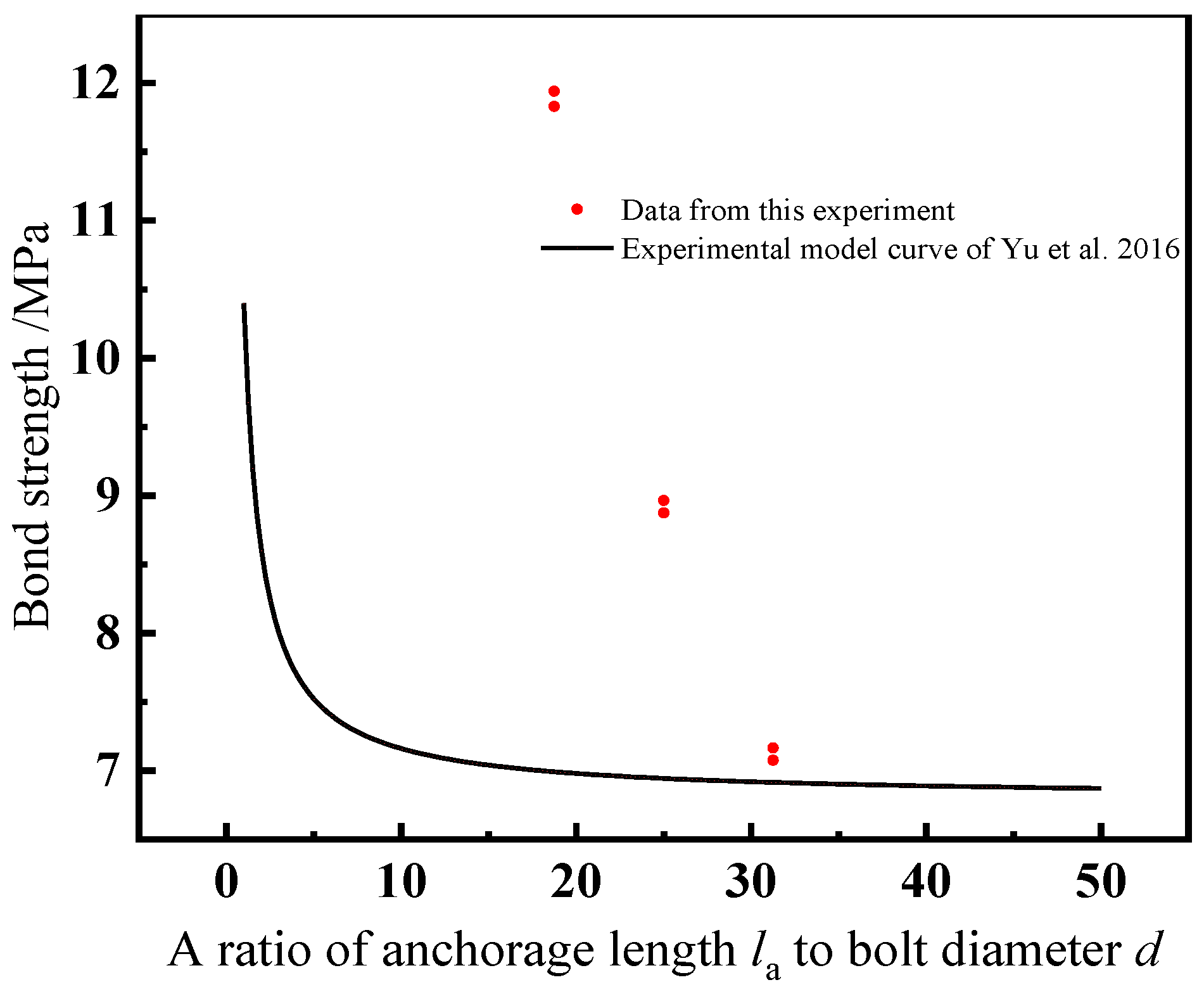
The high-strength bolt exhibits a significant yield point during the pulling process, and the corresponding stress at this point represents the bond strength between high-strength bolts and the CBGM. The relationships between bond strength and anchorage length for the six groups of broken bolts in this experiment were compared to the expression proposed by Yu et al. [29], as well as the bond strength expression, considering the effect of stirrup and the thickness of the concrete protective layer, as shown as Equation (8):
τ u = [ 0.94 + 0.50 ( d l a ) ] [ 3.02 + 0.71 ( c d ) ] f ts
where τu is the bond strength (MPa), c is the thickness of the concrete protective layer (mm) and fts is the splitting tensile strength of the CBGM (MPa).
The conversion formula [13] between the splitting tensile strength of CBGM and the compressive strength of the prismatic specimen of 40 mm × 40 mm × 160 mm can be written as follows:
f ts = 1 19.5 f c
where fc is the compressive strength of the prismatic specimen (MPa).
By comparing the experimental data to the above formula, the relationship between bond strength and anchorage length was illustrated in Figure 13.
As seen in Figure 13, the expression of bond strength proposed by Yu et al. [29] is not capable of accurately representing the bond strength in this study. This problem is due to the fact that the properties of bolts used in this test, such as strength and surface shape, are different to those of the normal steel bars. Therefore, the parameters corresponding to d/la in the expression proposed by Yu et al. [29] were modified as follows:
τ u = [ A + B ( d l a ) ] [ 3.02 + 0.71 ( c d ) ] f ts
where A and B are the fitted parameters.
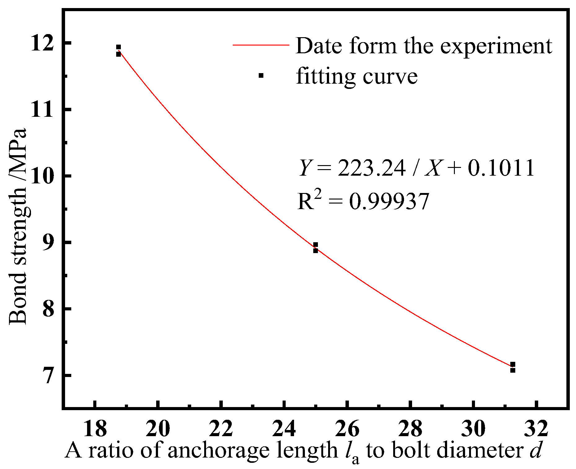
Using this formula to fit the experimental data, the values of A and B are 0.01398 and 30.8622, respectively. Thus, the bond strength formula of the broken bolt can be determined via Equation (11), and the fitting result is shown in Figure 14.
τ u = [ 0.01398 + 30.8622 ( d l a ) ] [ 3.02 + 0.71 ( c d ) ] f ts

6. Bond–Slip Constitutive Model

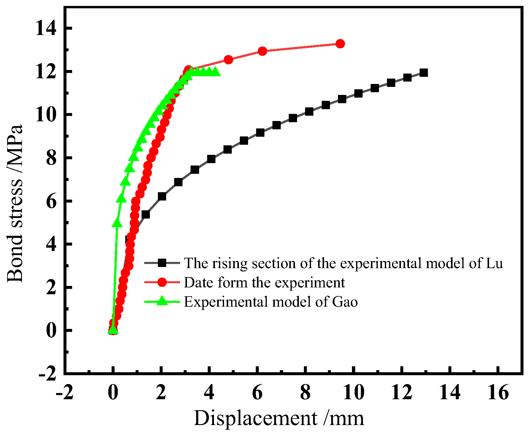
The fracture damage of the bolts occurred with an anchorage length of more than 300 mm in this study. Figure 11 shows the load–displacement curves for these specimens with different anchorage lengths. It can be seen that the curves can be divided into two stages: one stage extends from the start to the bolt yielding point, which is called the ascending stage, and another stage extends from the bolt yielding point to the bolt fracturing point, which is called the intensifying stage. The experimental data were compared with the ascending section of the bond–slip experimental model developed by Lu [30] and the bond–slip experimental model by Gao [31], as shown in Figure 15. As can be seen in Figure 15, the experimental data differ significantly from the two bond–slip curves; thus, neither of the curves can represent the bond–slip constitutive relationship in this experiment. Therefore, the bond–slip constitutive model of the fractured bolts was investigated by fitting the bond–slip curve.
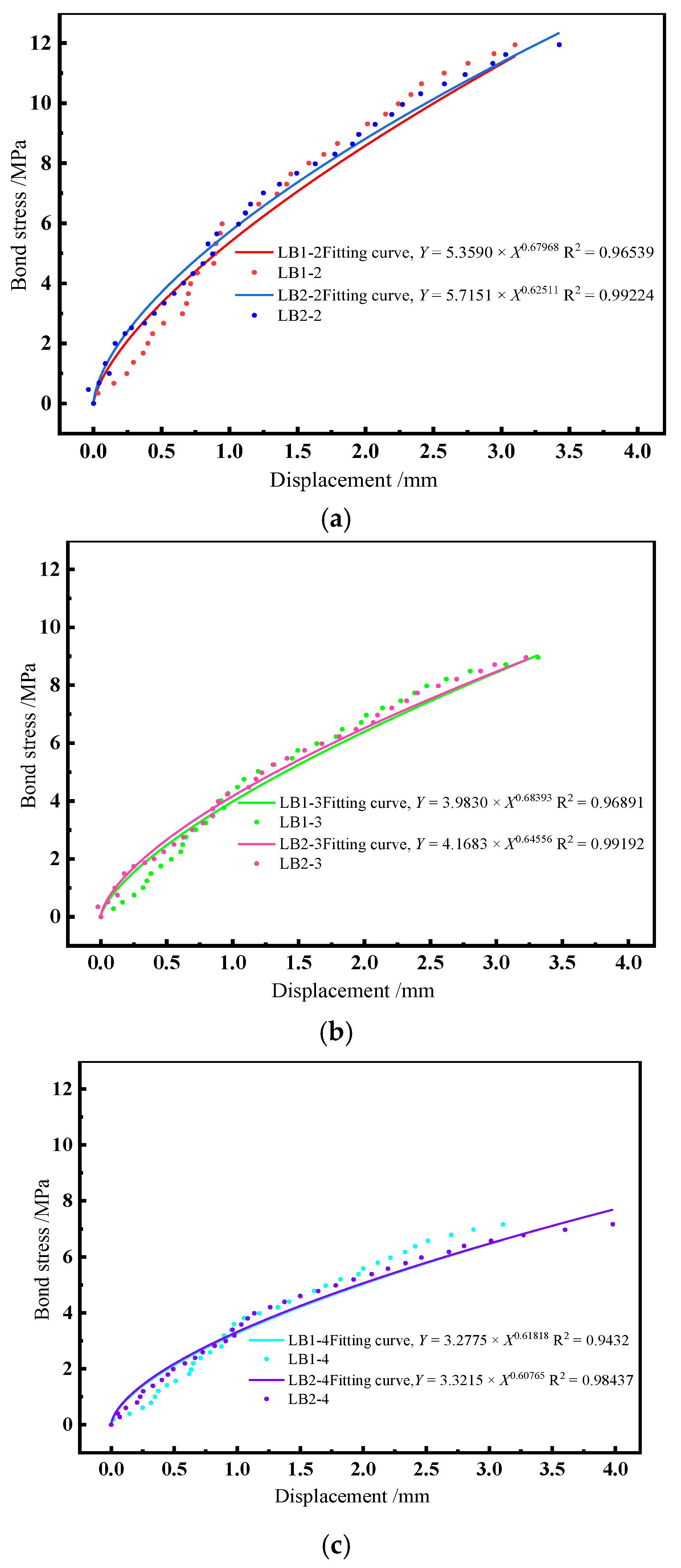
Upon analyzing the ascending stage of the fitted curve, a power function can be used to describe the change law of these curves. Referring to CEB-FIP 2010 [32] in regard to the curve expression of the ascending stage in the bond–slip relationship under monotonic loading, the power function can be written as:
τ = τ u ( s s 1 ) α
where s is the bolt displacement (mm), while s1 is the corresponding displacement of the bolt when it yields (mm).
The power function was chosen to fit the ascending stage, and the fitting results are shown in Figure 16.
Since the ascending stage of the bond stress–displacement curve is similar, the coefficients of each fitting formula can be averaged to obtain the bond stress–displacement constitutive model for the ascending stage of the fractured bolt, as well as the average values of six specimens, which is given by:
τ = τ u ( s s 1 ) 0.6434 ; 0 s s 1
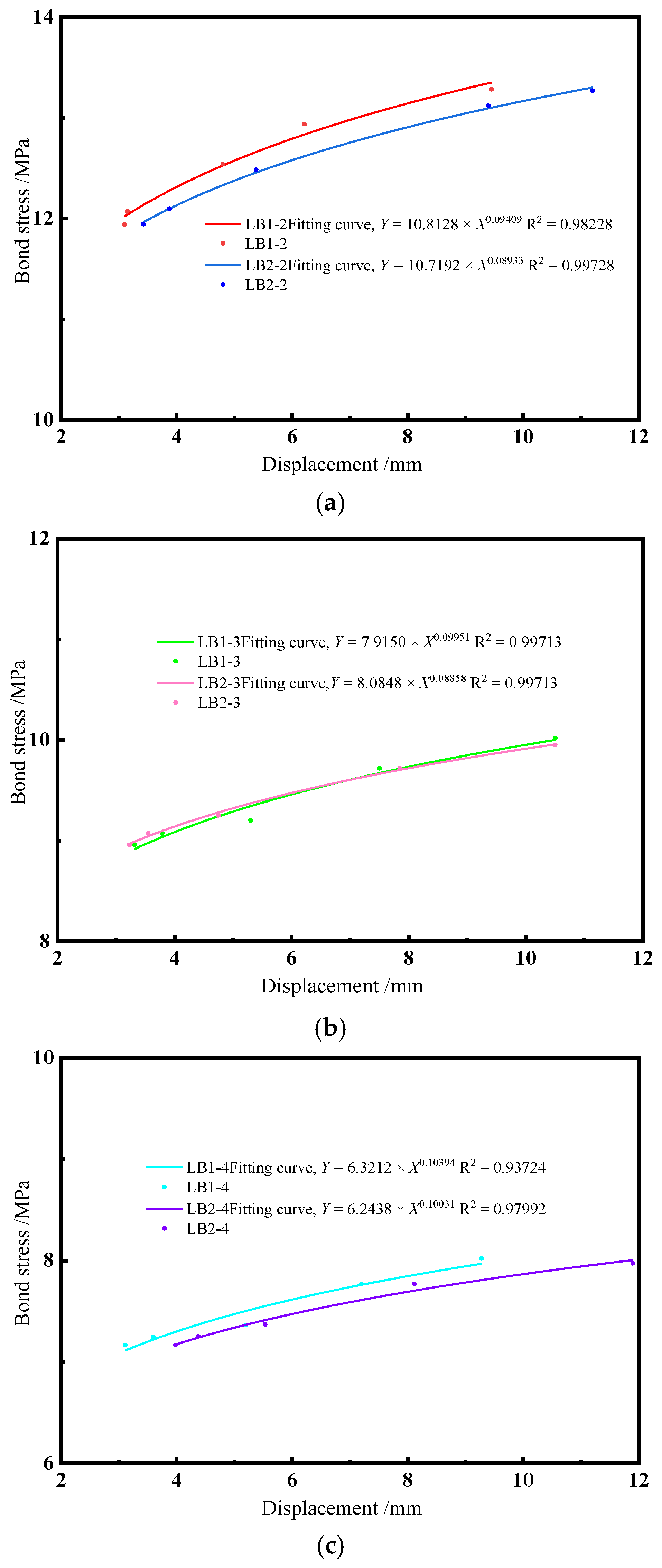
The intensifying stage corresponds to the process that occurs between the bolt yielding and fracturing. By observing the curve-change pattern, the power function is selected to fit the intensifying stage, and the fitting results are shown in Figure 17.
The fitting results are treated in the same way as the ascending stage, and the bond stress–displacement constitutive model for the intensifying stage of the fractured bolt is obtained as follows:
τ = 0.79905 τ max s 0.09596 ; s 1 < s s 2
where τmax is the maximum value of bond stress (MPa), while s2 is the corresponding bolt displacement that occurs when the bolt fractures (mm).

7. Conclusions

Based on the results presented in this study, the following conclusions can be drawn:
(1)
The high-strength bolt and the CBGM experienced bond–slip failure without square steel tube constraining when the specimens were composed of pre-cast concrete and high-strength bolt connected to the CBGM in a reserve hole or square steel tube with an anchorage length of less than 15 d. The specimens experienced splitting failure when the square steel tube was used as a constraint. The failure loads of specimens in LB-A were slightly greater than that of LB-B, which implies that the square steel tube had a constraining effect on the CBGM and improved the bonding property between high-strength bolt and the CBGM. When the anchorage lengths were more than 18 d, the high-strength bolts in both LB-A and LB-B fractured at the same load level, which reached the ultimate load of the high-strength bolts. Before the bolt fractured, the tensile force increased with the increase in anchorage lengths, whereas the bond strength decreased.
(2)
The bond strength–anchorage length relationships between high-strength bolts and the CBGM were analyzed, as were the bond strength–anchorage length relationships for bolts with different anchorage lengths and the special connection mode. A formula for determining bond strength–anchorage length relationships was proposed.
(3)
The bond–slip curves between the fractured bolt and the CBGM were investigated, and the curves were divided into ascending and intensifying stages. The bond–slip constitutive relationship was also determined by fitting the experimental curves.

Author Contributions

Investigation, P.L.; writing—original draft preparation, W.Z.; conceptualization, J.M.; writing—review and editing, L.L.; formal analysis, Y.C.; methodology, Z.Y. All authors have read and agreed to the published version of the manuscript.

Funding

This research was funded by the National Natural Science Foundation of China (grant numbers 52178182, 52108262 and U1934217) and the Science and Technology Research and Development Program Project of China railway group limited (Major Special Project, No.: 2020-Special-02, 2021-Special-08, 2022-Special-09; Major Project, No.: 2021-Special-02; Key Project, No.: 2021-Key-11, No.: 2022-Key-46). The authors have also received research grants from the National Science Foundation for Distinguished Young Scholars of Hunan Province (2022JJ10075), the Natural Science Foundation of Hunan Province of China (2020JJ5982) and the Hunan Innovative Province Construction Special Project (2020GK4058).

Institutional Review Board Statement

Not applicable.

Informed Consent Statement

Not applicable.

Data Availability Statement

The data presented in this study are available on request from the corresponding author. The data are not publicly available due to privacy restrictions.

Acknowledgments

The authors thank the National Natural Science Foundation of China, the Science and Technology Research and Development Program Project of China Railway Group Limited, the National Science Foundation for Distinguished Young Scholars of Hunan Province, the Natural Science Foundation of Hunan Province of China and the Hunan Innovative Province Construction Special Project for funding this research, as well as anonymous reviewers for their contribution to this paper. He Sasa, Zhang Ning and Hu Cheng also made great contributions.

Conflicts of Interest

The authors declare no conflict of interest.

References

  1. Dhandapani, B.P.; Mullapudi, R.S. Design and performance characteristics of cement grouted bituminous mixtures—A review. Constr. Build. Mater. 2023, 369, 130586. [Google Scholar]
  2. Perret, S.; Khayat, K.H.; Gagnon, E.; Rhazi, J. Repair of 130-year old masonry bridge using high-performance cement grout. J. Bridge Eng. 2002, 7, 31–38. [Google Scholar] [CrossRef]
  3. Hayashi, Y.; Nakatsuka, T.; Miwake, I.; Suzuki, K. Mechanical performance of grout-filled coupling steel sleeves under cyclic loads. J. Struct. Constr. Eng. 1997, 62, 91–98. [Google Scholar] [CrossRef] [PubMed] [Green Version]
  4. Darwin, D.; Zavaregh, S.S. Bond Strength of Grouted Reinforcing Bars. ACI Struct. J. 1993, 93, 486–495. [Google Scholar]
  5. Raynor, D.J.; Lehman, D.E.; Stanton, J.F. Bond-Slip Response of Reinforcing Bars Grouted in Ducts. ACI Struct. J. 2002, 99, 568–576. [Google Scholar]
  6. Moosavi, M.; Jafari, A.; Khosravi, A. Bond of cement grouted reinforcing bars under constant radial pressure. Cem. Concr. Compos. 2005, 27, 103–109. [Google Scholar] [CrossRef]
  7. Alias, A.; Sapawi, F.; Kusbiantoro, A.; Zubir, M.A.; Rahman, A.B.A. Performance of Grouted Splice Sleeve Connector Under Tensile Load. J. Mech. Eng. Sci. 2014, 7, 1094–1102. [Google Scholar]
  8. Hosseini, S.J.A.; Rahman, A.B.A.; Osman, M.H.; Saim, A.; Adnan, A. Bond behavior of spirally confined splice of deformed bars in grout. Constr. Build. Mater. 2015, 80, 180–194. [Google Scholar] [CrossRef]
  9. Hosseini, S.J.A.; Rahman, A.B.A. Effects of spiral confinement to the bond behavior of deformed reinforcement bars subjected to axial tension. Eng. Struct. 2016, 112, 1–13. [Google Scholar] [CrossRef]
  10. Ling, J.H.; Rahman, A.B.A.; Ibrahim, I.S.; Hamid, Z.A. Tensile capacity of grouted splice sleeves. Eng. Struct. 2016, 111, 285–296. [Google Scholar] [CrossRef]
  11. Zhou, Y.H.; Ou, Y.C.; Lee, G.C. Bond-slip responses of stainless reinforcing bars in grouted ducts. Eng. Struct. 2017, 141, 651–665. [Google Scholar] [CrossRef]
  12. Li, X.D.; Lu, C.D.; Cui, Y.F.; Zhou, L.C. Study on the bond properties between steel bar and fiber reinforced concrete after high temperatures. Structures 2023, 49, 889–902. [Google Scholar]
  13. Wu, F.Y. Experimental Study on Mechanical Properties of Grout and Bond Behavior between Steel Bar and Grout; Hunan University: Changsha, China, 2019. [Google Scholar]
  14. Yuan, J.J.; Shen, D.J.; Xu, Z.L.; Li, M.; Wen, C.Y.; Zong, D. Effect of bond length on bond behavior between basalt fiber-reinforced polymer sheet and concrete. Constr. Build. Mater. 2023, 392, 131586. [Google Scholar]
  15. Hu, X.P.; Peng, G.; Niu, D.T.; Wang, J. Bond properties of deformed steel bars in concrete during construction under reversed cyclic loading. Constr. Build. Mater. 2019, 223, 817–829. [Google Scholar]
  16. Liu, P.; Xie, S.S.; Liu, L.; Zheng, Z.H.; Zhang, N.; He, S.S.; Wu, Y.Y.; Xu, W.; Chen, Y.; Kuang, Y.C.; et al. Experimental study on bonding strength between high-strength bolt and cement-based grouting material. J. Mater. Res. Technol. 2022, 19, 2191–2203. [Google Scholar] [CrossRef]
  17. Stanish, K.D.; Hooton, R.D.; Pantazopoulou, S.J. Corrosion effects on bond strength in reinforced concrete. ACI Struct. J. 1999, 96, 915–921. [Google Scholar]
  18. Vidal, T.; Castel, A.; François, R. Corrosion process and structural performance of a 17 year old reinforced concrete beam stored in chloride environment. Cem. Concr. Res. 2007, 37, 1551–1561. [Google Scholar] [CrossRef]
  19. Chung, L.; Cho, S.H.; Jay, K.J.; Yi, S. Correction factor suggestion for ACI development length provisions based on flexural testing of RC slabs with various levels of corroded reinforcing bars. Eng. Struct. 2004, 26, 1013–1026. [Google Scholar] [CrossRef]
  20. GB/T 50152-2012; Standard Methods for Testing of Concrete Structures. China Architecture and Building Press: Beijing, China, 2012.
  21. Sulaiman, M.F.; Ma, C.K.; Apandi, N.M.; Chin, S. A Review on Bond and Anchorage of Confined High-strength Concrete. Structures 2017, 11, 97–109. [Google Scholar]
  22. GB/T 17671-2021; Method of Testing Cements-Determination of Strength. Standards Press of China: Beijing, China, 2021.
  23. GB 50010-2010; Code for Design of Concrete Structures. China Architecture and Building Press: Beijing, China, 2015.
  24. BS EN 1992-1-1; Eurocode 2: Design of Concrete Structures. British Standards Institution: London, UK, 2004.
  25. GB/T 50081-2019; Standard for Test Methods of Concrete Physical and Mechanical Properties. China Architecture and Building Press: Beijing, China, 2019.
  26. GB/T 228.1-2021; Metallic Materials-Tensile Testing-Part 1: Method of Test at Room Temperature. Standards Press of China: Beijing, China, 2021.
  27. Zhang, D.X.; Yang, W.J. Experimental Research on Bond Behaviors between Shale Ceramsite Lightweight Aggregate Concrete and Bars through Pullout Tests. J. Mater. Civ. Eng. 2015, 27, 06014030. [Google Scholar] [CrossRef]
  28. Zhu, G.M.; Ma, Y.X.; Tan, K.H. Experimental and analytical investigation on precast concrete-encased concrete-filled steel tube column-to-column dry connections under axial tension. Structures 2022, 45, 523–541. [Google Scholar] [CrossRef]
  29. Yu, Q.; Yuan, Y.H.; You, G.S. Experiment and Finite Element Analysis on Bonding Properties Between Deformed Bars and Grouting Material. Struct. Eng. 2016, 32, 113–122. [Google Scholar]
  30. Lu, Z.F.; Mao, L.; Liu, M.Y. Performance simulation and parameter analysis of bolted anchor head connection mode for reserved grouting hole. J. Wuhan Univ. Technol. Transp. Sci. Eng. 2021, 45, 297–302. [Google Scholar]
  31. Gao, X.L. Experimental Study and Numerical Simulation of Bonding Performance of High Performance Concrete to Steel Reinforcement; Tongji University: Shanghai, China, 2003. [Google Scholar]
  32. fib Model Code for Concrete Structures 2010; Ernst and Sohn: Berlin, Germany, 2013.
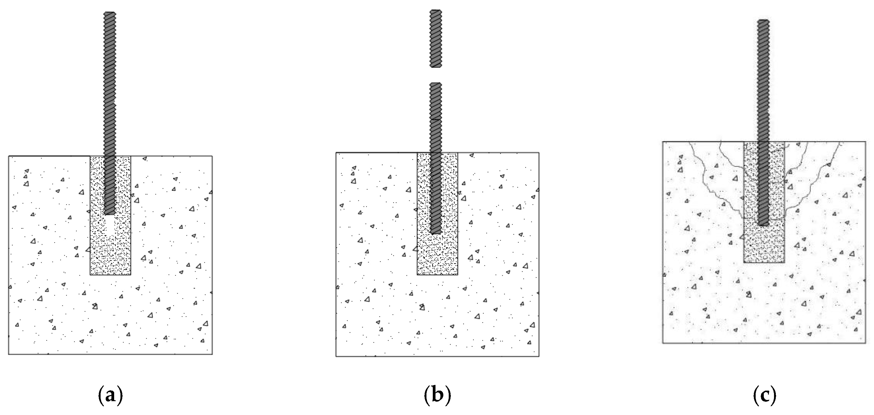
Figure 1. Schematic diagram of failure modes between bolt and Cement-based grouting materials (CBGM): (a) bolt pull-out failure; (b) bolt fracture failure; (c) CBGM splitting failure.
Applsci 13 08269 g001
Figure 2. Schematic diagram of bolt damage force. (a) Schematic diagram of bolt pulls out/splitting failure force. (b) Schematic diagram of bolt fracture/failure force.
Applsci 13 08269 g002
Figure 3. Mechanical properties test of CBGM. (a) Compressive experiment of CBGM. (b) Flexural experiment of CBGM.
Applsci 13 08269 g003
Figure 4. Testing process of concrete.
Applsci 13 08269 g004
Figure 5. Bond Strength test. (a) Loading setup. (b) Broken section of bolt.
Applsci 13 08269 g005
Figure 6. Schematic diagram of the specimens (unit: mm). (a) Profile of LB-A. (b) Profile of LB-B. (c) Top view of LB-A. (d) Top view of LB-B.
Applsci 13 08269 g006
Figure 7. Casting process used for the specimens.
Applsci 13 08269 g007
Figure 8. Loading device. (a) Loading device diagram. (b) Heart-piercing hydraulic jack.
Applsci 13 08269 g008
Figure 9. Failure modes in LB-A. (a) Bolt fracture failure. (b) Bolt pull-out failure.
Applsci 13 08269 g009
Figure 10. Failure modes in LB-B. (a) Bolt fracture failure. (b) Specimen splitting failure.
Applsci 13 08269 g010
Figure 11. Schematic diagram of load–displacement curves of each group. (a) LB-A. (b) LB-B.
Applsci 13 08269 g011
Figure 12. Schematic diagram of comparison of each specimen maximum load.
Applsci 13 08269 g012
Figure 13. Schematic diagram of the relationship between bond strength and anchorage length [29].
Applsci 13 08269 g013
Figure 14. Schematic diagram of the bond strength fitting curve of the fractured bolt.
Applsci 13 08269 g014
Figure 15. Comparison between different bond−slip constitutive curves.
Applsci 13 08269 g015
Figure 16. Fitting schematic diagram of the bond stress–displacement at the ascending stage. (a) Fitting ascending stage with an anchorage length of 300 mm. (b) Fitting ascending stage with an anchorage length of 400 mm (c) Fitting ascending stage with an anchorage length of 500 mm.
Applsci 13 08269 g016
Figure 17. Fitting schematic diagram of the bond stress–displacement relationship at the intensifying stage. (a) Fitting intensifying stage with an anchorage length of 300 mm. (b) Fitting intensifying stage with an anchorage length of 400 mm. (c) Fitting intensifying stage with an anchorage length of 500 mm.
Applsci 13 08269 g017
Table 1. Mechanical properties of CBGM.
MaterialAverage Compressive Strength at 28 d/MPaAverage Flexural Strength at 28 d/MPa
CBGM71.511.32
Table 2. Compressive strength of concrete.
C40 ConcreteCompressive Strength at 28 d/MPa
Specimen 140.7
Specimen 241.2
Specimen 340
Specimen 440.3
Specimen 541.5
Specimen 641.7
Average40.9
Table 3. Mechanical properties of high-strength bolts.
Diameter of the Bolt/mmAverage Tensile Yield Strength/MPaAverage Ultimate Tensile Strength/MPa
16907.301045.98
Table 4. Specimen types and geometry parameters.
Experimental
Design
Grouping NumberDiameter of Bolt (d/mm)Anchorage Length (la/mm)la/dAnchorage Mode of Bolts
LB-ALB 1-11624015Bolts are directly embedded into square steel tubes with a reserved section of 60 mm × 60 mm
LB 1-21630018.75
LB 1-31640025
LB 1-41650031.25
LB-BLB 2-11624015Bolts are directly embedded into holes with a reserved section of 60 mm × 60 mm
LB 2-21630018.75
LB 2-31640025
LB 2-41650031.25
Table 5. Failure modes of the test specimens.
Experimental DesignGrouping NumberDiameter of Bolt (d/mm)Anchorage Length (la/mm)Failure Mode
LB-ALB 1-116240Bolt pulled out of CBGM
LB 1-216300Bolt fracture failure
LB 1-316400Bolt fracture failure
LB 1-416500Bolt fracture failure
LB-BLB 2-116240Bolt pulled out of CBGM and cracks
occurred in concrete
LB 2-216300Bolt fracture failure
LB 2-316400Bolt fracture failure
LB 2-416500Bolt fracture failure
Disclaimer/Publisher’s Note: The statements, opinions and data contained in all publications are solely those of the individual author(s) and contributor(s) and not of MDPI and/or the editor(s). MDPI and/or the editor(s) disclaim responsibility for any injury to people or property resulting from any ideas, methods, instructions or products referred to in the content.