
Using A Rotary Spring-Driven Gripper to Manipulate Objects of Diverse Sizes and Shapes


Abstract
:1. Introduction
2. Materials and Methods
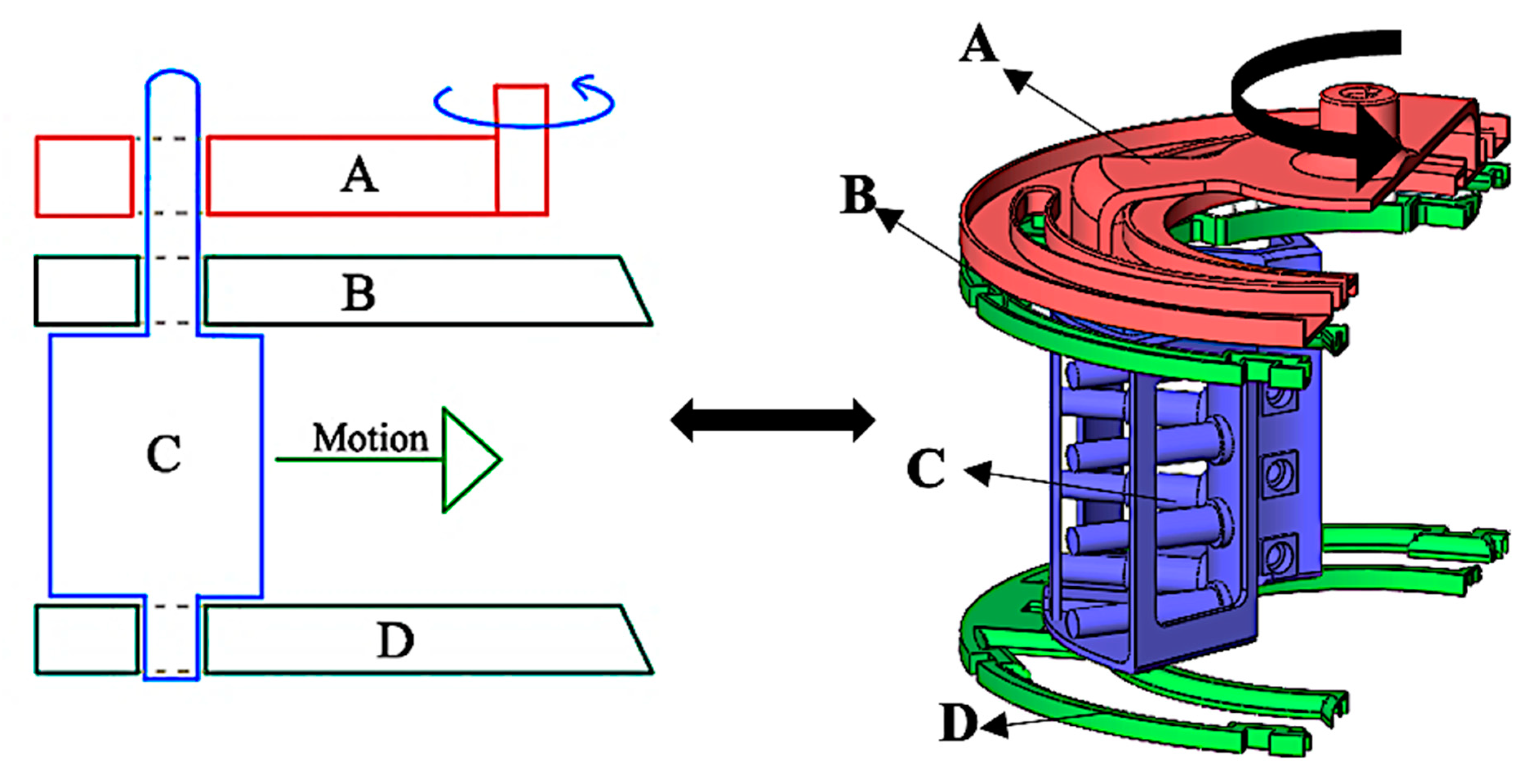
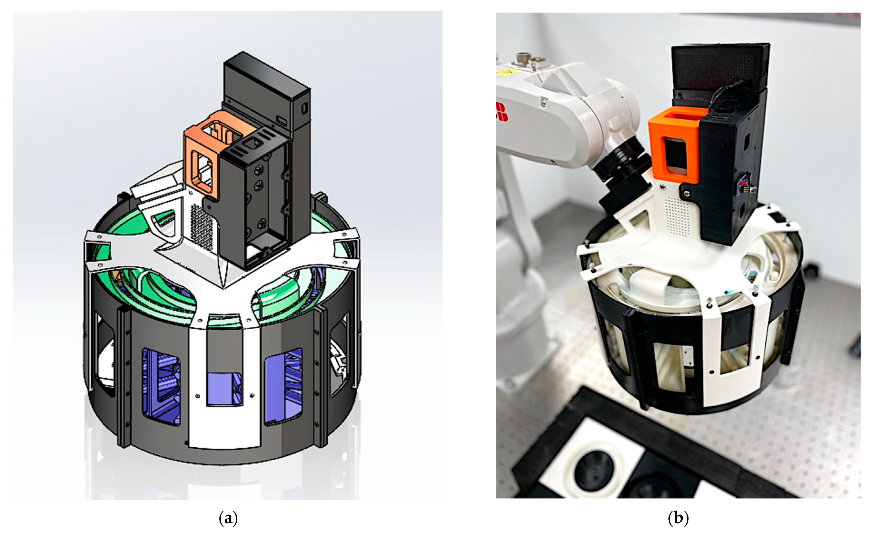
2.1. Parts and Specification of the Mechanism
2.1.1. Mechanical Advantage
2.1.2. Material Selection
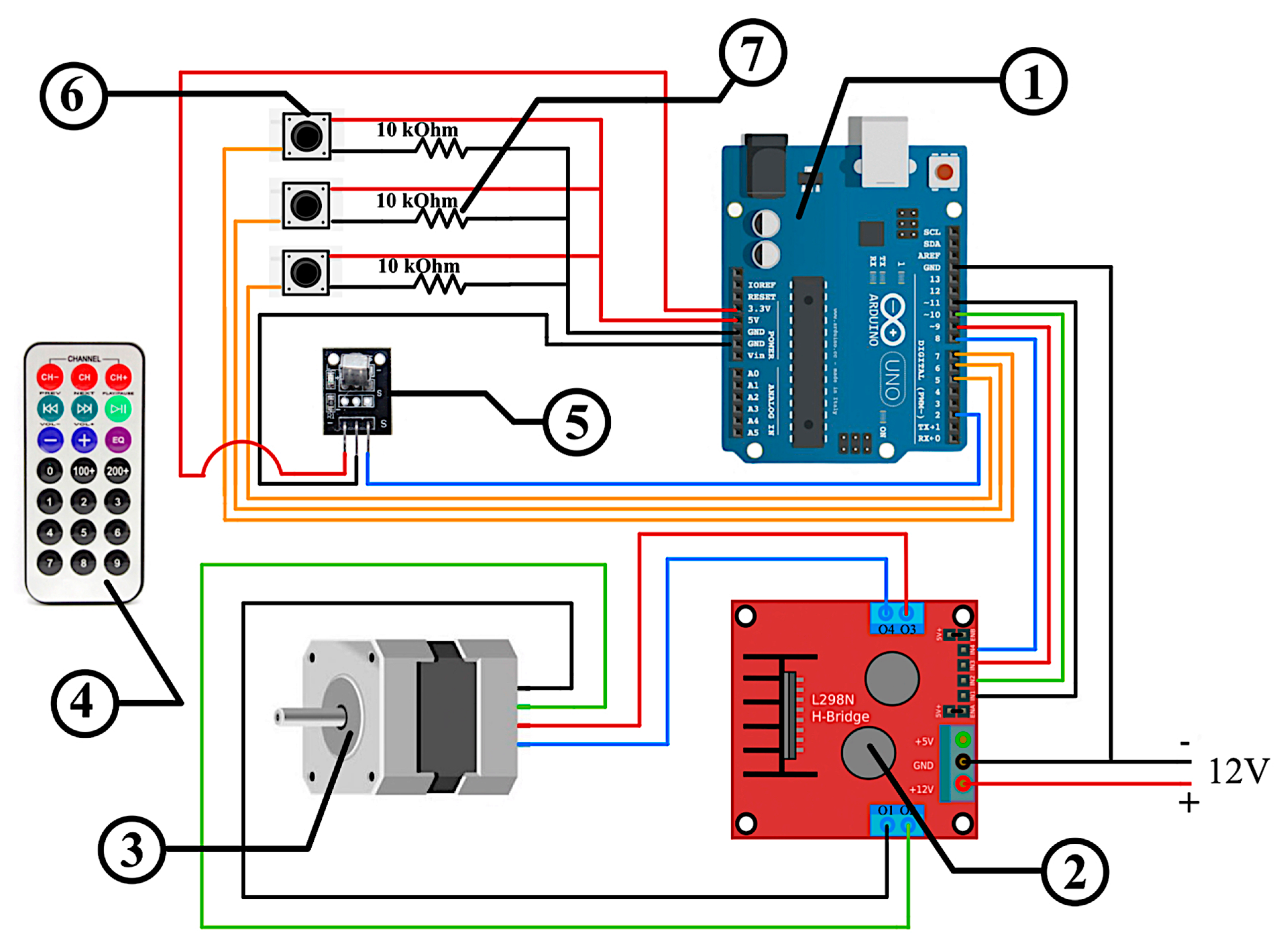
2.1.3. Electrical Component
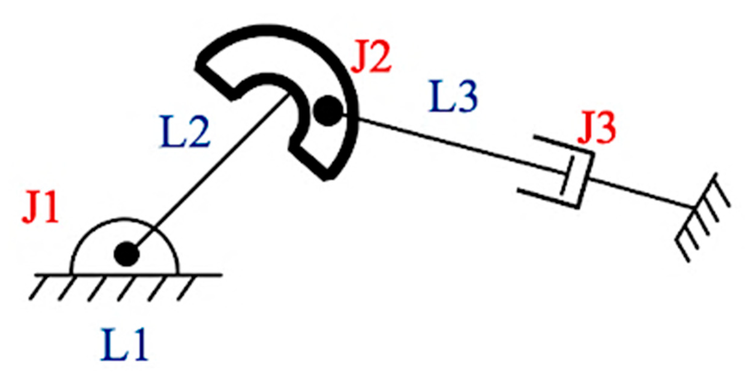
2.2. Kinematic Analysis
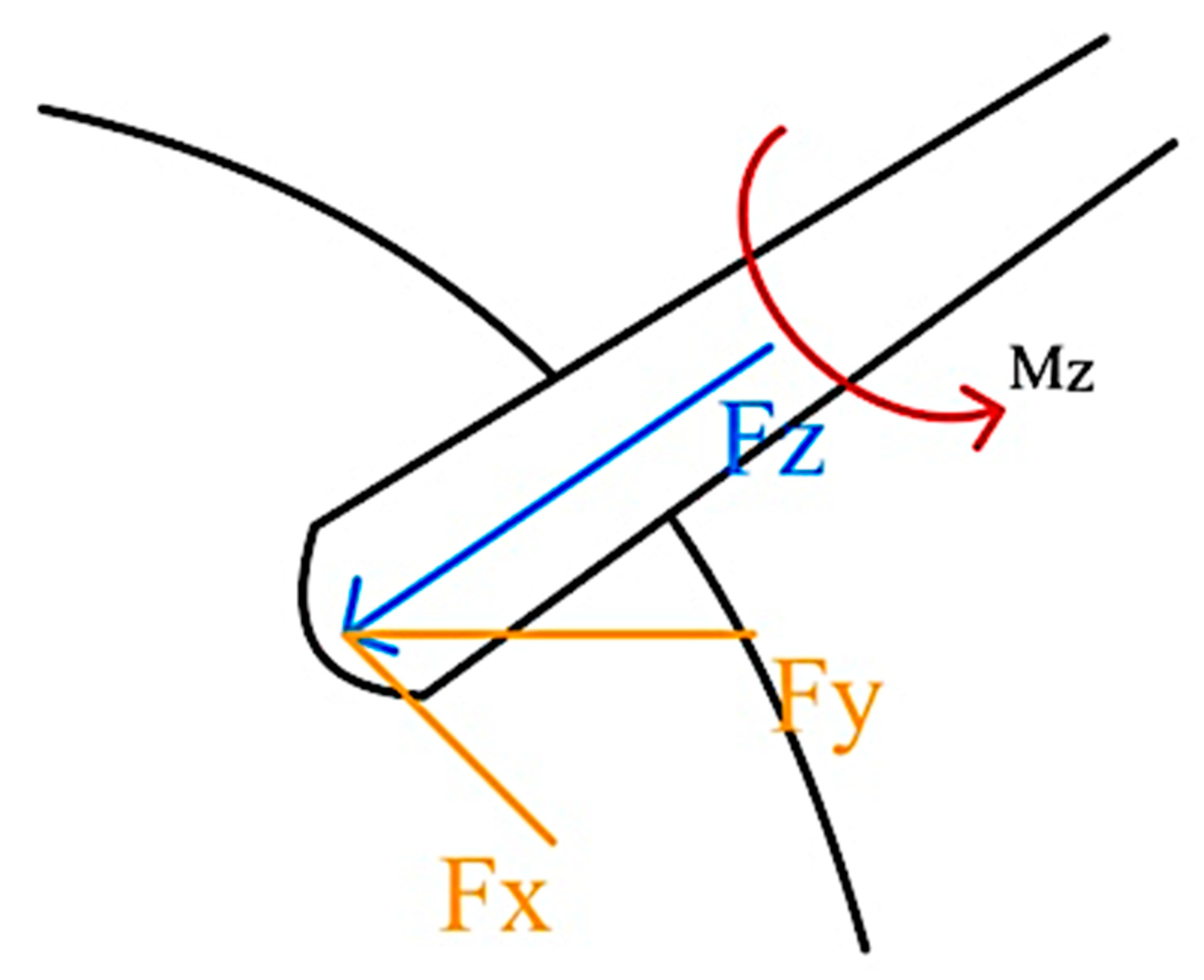
2.3. Force Analysis
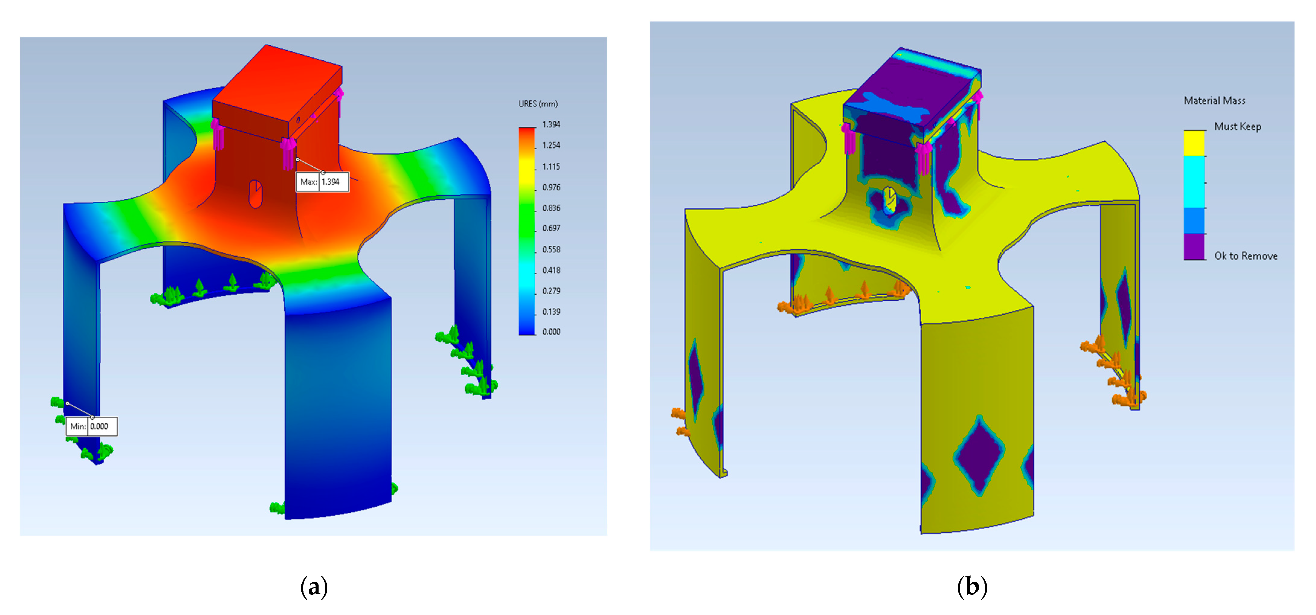
2.4. Stress Analysis
3. Results
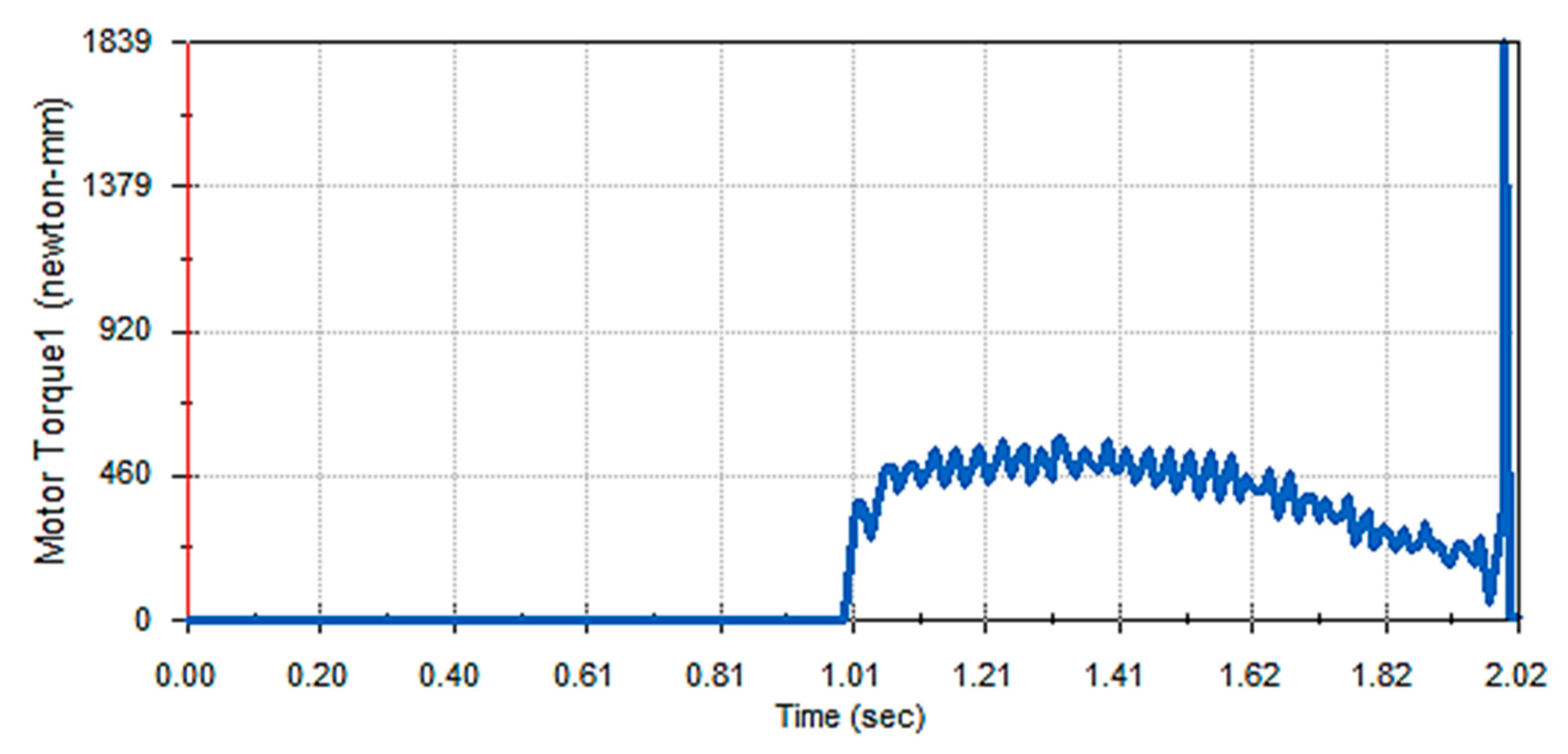
3.1. Motion Study
3.2. Robotic Arm Path Planning for Efficient Task Execution
- Case I: Two collinear joints. In this case, when there are two joints with their z-axis in the same direction, the robotic end effector is unable to move at least in certain directions.
- Case II: Three coplanar and parallel revolute joints.
- Case III: Four revolute joints intersecting at a common point.
- Case IV: Four coplanar revolute joints.
- Case V: Six revolute joints intersecting the common line.
4. Discussions and Conclusions
- Innovative novel gripper design for differently shaped and sized objects;
- Gripper design for soft grasping that also works for rigid objects;
- Able to achieve both force-closure and form-closure grasping;
- Grasping forces from all lateral directions;
- Minimal actuation and simple open-loop control;
- Foundation for future research and sophistication.
Author Contributions
Funding
Institutional Review Board Statement
Informed Consent Statement
Data Availability Statement
Acknowledgments
Conflicts of Interest
References
- Anagnoste, S. Robotic Automation Process-The next Major Revolution in Terms of Back Office Operations Improvement. Proc. Int. Conf. Bus. Excel. 2017, 11, 676–686. [Google Scholar] [CrossRef]
- Dixon, J.; Hong, B.; Wu, L. The Robot Revolution: Managerial and Employment Consequences for Firms. Manag. Sci. 2021, 67, 5586–5605. [Google Scholar] [CrossRef]
- Kastan, B. Autonomous Weapons Systems: A Coming Legal ”Singularity”? U Ill. JL Tech. Pol. 2013, 2013, 45. [Google Scholar]
- Samadikhoshkho, Z.; Zareinia, K.; Janabi-Sharifi, F. A Brief Review on Robotic Grippers Classifications. In Proceedings of the 2019 IEEE Canadian Conference of Electrical and Computer Engineering (CCECE), Edmonton, AB, Canada, 5–8 May 2019; pp. 1–4. [Google Scholar]
- Bicchi, A.; Kumar, V. Robotic Grasping and Contact: A Review. In Proceedings of the 2000 ICRA. Millennium Conference. IEEE International Conference on Robotics and Automation. Symposia Proceedings (Cat. No. 00CH37065), San Francisco, CA, USA, 24–28 April 2000; Volume 1, pp. 348–353. [Google Scholar]
- Jacobsen, S.; Iversen, E.; Knutti, D.; Johnson, R.; Biggers, K. Design of the Utah/MIT Dextrous Hand. In Proceedings of the 1986 IEEE International Conference on Robotics and Automation, San Francisco, CA, USA, 7–10 April 1986; Volume 3, pp. 1520–1532. [Google Scholar]
- Saito, F.; Fukuda, T.; Arai, F. Swing and Locomotion Control for a Two-Link Brachiation Robot. IEEE Control Syst. Mag. 1994, 14, 5–12. [Google Scholar]
- Lasi, H.; Fettke, P.; Kemper, H.-G.; Feld, T.; Hoffmann, M. Industry 4.0. Bus. Inf. Syst. Eng. 2014, 6, 239–242. [Google Scholar] [CrossRef]
- Reddy, P.V.P.; Suresh, V. A Review on Importance of Universal Gripper in Industrial Robot Applications. Int. J. Mech. Eng. Robot. Res. 2013, 2, 255–264. [Google Scholar]
- Sherwani, F.; Asad, M.M.; Ibrahim, B.S.K.K. Collaborative Robots and Industrial Revolution 4.0 (Ir 4.0). In Proceedings of the 2020 International Conference on Emerging Trends in Smart Technologies (ICETST), Karachi, Pakistan, 26–27 March 2020; pp. 1–5. [Google Scholar]
- Dario, P.; Guglielmelli, E.; Allotta, B.; Carrozza, M.C. Robotics for Medical Applications. IEEE Robot. Autom. Mag. 1996, 3, 44–56. [Google Scholar] [CrossRef]
- Kleeberger, K.; Bormann, R.; Kraus, W.; Huber, M.F. A Survey on Learning-Based Robotic Grasping. Curr. Robot. Rep. 2020, 1, 239–249. [Google Scholar] [CrossRef]
- Shorthose, O.; Albini, A.; He, L.; Maiolino, P. Design of a 3D-Printed Soft Robotic Hand with Integrated Distributed Tactile Sensing. IEEE Robot. Autom. Lett. 2022, 7, 3945–3952. [Google Scholar] [CrossRef]
- Wang, Y.; Wu, X.; Mei, D.; Zhu, L.; Chen, J. Flexible Tactile Sensor Array for Distributed Tactile Sensing and Slip Detection in Robotic Hand Grasping. Sens. Actuators Phys. 2019, 297, 111512. [Google Scholar] [CrossRef]
- Deng, Z.; Jonetzko, Y.; Zhang, L.; Zhang, J. Grasping Force Control of Multi-Fingered Robotic Hands through Tactile Sensing for Object Stabilization. Sensors 2020, 20, 1050. [Google Scholar] [CrossRef] [Green Version]
- Ntagios, M.; Nassar, H.; Pullanchiyodan, A.; Navaraj, W.T.; Dahiya, R. Robotic Hands with Intrinsic Tactile Sensing via 3D Printed Soft Pressure Sensors. Adv. Intell. Syst. 2020, 2, 1900080. [Google Scholar] [CrossRef] [Green Version]
- Hao, Y.; Gong, Z.; Xie, Z.; Guan, S.; Yang, X.; Ren, Z.; Wang, T.; Wen, L. Universal Soft Pneumatic Robotic Gripper with Variable Effective Length. In Proceedings of the 2016 35th Chinese Control Conference (CCC), Chengdu, China, 27–29 July 2016; pp. 6109–6114. [Google Scholar]
- Song, S.; Drotlef, D.-M.; Paik, J.; Majidi, C.; Sitti, M. Mechanics of a Pressure-Controlled Adhesive Membrane for Soft Robotic Gripping on Curved Surfaces. Extreme Mech. Lett. 2019, 30, 100485. [Google Scholar] [CrossRef]
- Li, H.; Yao, J.; Wei, C.; Zhou, P.; Xu, Y.; Zhao, Y. An Untethered Soft Robotic Gripper with High Payload-to-Weight Ratio. Mech. Mach. Theory 2021, 158, 104226. [Google Scholar] [CrossRef]
- Müller, A.; Aydemir, M.; Glodde, A.; Dietrich, F. Design Approach for Heavy-Duty Soft-Robotic-Gripper. Procedia CIRP 2020, 91, 301–305. [Google Scholar] [CrossRef]
- Song, E.J.; Lee, J.S.; Moon, H.; Choi, H.R.; Koo, J.C. A Multi-Curvature, Variable Stiffness Soft Gripper for Enhanced Grasping Operations. Actuators 2021, 10, 316. [Google Scholar] [CrossRef]
- Wang, D.; Wu, X.; Zhang, J.; Du, Y. A Pneumatic Novel Combined Soft Robotic Gripper with High Load Capacity and Large Grasping Range. Actuators 2021, 11, 3. [Google Scholar] [CrossRef]
- Zheng, Y.; Lei, G.; Zhang, M.; Che, Q. Mechanical Design and Analysis of a Gripper for Non-Cooperative Target Capture in Space. Adv. Mech. Eng. 2018, 10, 1687814018810649. [Google Scholar] [CrossRef] [Green Version]
- Mo, A.; Zhang, W. A Novel Universal Gripper Based on Meshed Pin Array. Int. J. Adv. Robot. Syst. 2019, 16, 1729881419834781. [Google Scholar] [CrossRef] [Green Version]
- Tavakoli, M.; Marques, L.; de Almeida, A.T. Flexirigid, a Novel Two Phase Flexible Gripper. In Proceedings of the 2013 IEEE/RSJ International Conference on Intelligent Robots and Systems, Tokyo, Japan, 3–7 November 2013; pp. 5046–5051. [Google Scholar]
- Kang, L.; Kim, S.-H.; Yi, B.-J. Modeling, Design, and Implementation of an Underactuated Gripper with Capability of Grasping Thin Objects. Machines 2021, 9, 347. [Google Scholar] [CrossRef]
- Mo, A.; Fu, H.; Luo, C.; Zhang, W. Concentric Rotation Pin Array Gripper for Universal Grasp. In Proceedings of the 2018 3rd International Conference on Advanced Robotics and Mechatronics (ICARM), Singapore City, Singapore, 18–20 July 2018; pp. 112–117. [Google Scholar]
- Thomas, W.; Wegrowski, P.; Lemirick, J.; Deemyad, T. Lightweight Foldable Robotic Arm for Drones. In Proceedings of the 2022 Intermountain Engineering, Technology and Computing (IETC), Orem, UT, USA, 14–15 May 2022; pp. 1–6. [Google Scholar]
- PKP245D23A2-R2E/PLE40-40B/P00027, Stepper Motor with Planetary Gearhead (40:1). Oriental Motor USA. Available online: https://catalog.orientalmotor.com/item/42mm-frame-stepper-motors/42mm-pkp-series-2-phase-bipolar-stepper-motors/pkp245d23a2-r2e-ple40-40b-p00027 (accessed on 19 May 2023).
- Deemyad, T.; Hassanzadeh, N.; Perez-Gracia, A. Coupling Mechanisms for Multi-Fingered Robotic Hands with Skew Axes. In Mechanism Design for Robotics, Proceedings of the 4th IFToMM Symposium on Mechanism Design for Robotics, Udine, Italy, 11–13 September 2018; Springer: Berlin/Heidelberg, Germany, 2019; pp. 344–352. [Google Scholar]
- Ngoc, T.L.; Nguyen, T.L. Quasi-Physical Modeling of Robot IRB 120 Using Simscape Multibody for Dynamicand Control Simulation. Turk. J. Electr. Eng. Comput. Sci. 2020, 28, 1949–1964. [Google Scholar]


| Part’s Name | Dimensions (cm) 1 | Part No. |
|---|---|---|
| Outer Shell A | H = 14.7, OR = 14.3, T = 0.3 | 1 |
| Outer Shell B | H = 14.7, R = 14.3, T = 0.3 | 2 |
| Rectangular Slot Plate (Bottom) | OR = 13.9, IR = 8, T = 0.75 | 3 |
| Bearing Ball | D = 1 | 4 |
| Shutter | OR = 11, IR = 5, H = 15.25 | 5 |
| Linear Slot Plate (Top) | OR = 13.9, IR = 6.8, T = 0.75 | 6 |
| Curvilinear Slot Plate | OR = 13.9, IR = 6.8, H = 5.4 | 7 |
| Top Cover | OR = 14.8, H = 24.6 | 8 |
| Motor Cover | 6.3 × 6.3 × 7.8 | 9 |
| Electronics Box | 10.2 × 10.275 × 14.7 | 10 |
| Wire Cap | 10.2 × 3.075 × 5.19 | 11 |
| Piston | R = 0.15, H = 6 | 12 |
| Spring | R = 0.5, T = 0.05, H = 2.5 | 13 |
| Piston Blocker | OR = 0.6, IR = 0.25, H = 0.4 | 14 |
| Properties | 6061 Aluminum Alloy | ABS |
|---|---|---|
| Yield Strength | 276 MPa | 29.6 MPa |
| Ultimate Tensile Strength | 310 MPa | 40 MPa |
| Elastic Modulus | 69,000 MPa | 2000 MPa |
| Poisson’s Ratio | 0.33 | 0.394 |
| Mass Density | 2700 kg/m3 | 1020 kg/m3 |
| Shear Modulus | 26,000 MPa | 318.9 MPa |
| Electrical Components | Quantity | Component No. |
|---|---|---|
| Arduino Uno R3 | 1 | 1 |
| L298N Motor Driver Module | 1 | 2 |
| PKP Series 2-Phase Stepper Motor | 1 | 3 |
| Remote Control Module | 1 | 4 |
| HX1838 VS1838 NEC IR Receiver | 1 | 5 |
| 6 mm × 6 mm × 5 mm Tactile Push Button | 3 | 6 |
| 10 kΩ Resistor | 3 | 7 |
| Joint Orientation Angles for All Six Joints q1, q2, q3, q4, q5, q6 (Degrees) | Determinant | Rank |
|---|---|---|
| 1.98, 3.10, −9.94, −3.12, 56.79, 6.58 | −0.0196 | 6 |
| −26.19, 20.20, −27.12, 17.75, 59.85, −26.26 | −0.0198 | 6 |
| −26.19, 18.38, 6.15, 30.32, 31.47, −43.63 | −0.0152 | 6 |
| −26.19, 22.05, 12.92, 42.40, 43.01, −57.16 | −0.0186 | 6 |
| −26.19, 19.09, 8.08, 32.67, 29.24, −46.35 | −0.0143 | 6 |
| −26.19, 18.49, −17.33, 19.31, 52.86, −29.06 | −0.0118 | 6 |
| 15.60, 12.09, −8.52, 15.09, 48.65, 25.56 | −0.0199 | 6 |
| 39.66, 35.63, −39.88, −28.25, 64.97, 48.83 | −0.0144 | 6 |
| 39.66, 34.93, −6.41, −44.15, 38.01, 73.47 | −0.0172 | 6 |
| 39.66, 38.77, −2.22, −52.66, 32.66, 83.87 | −0.0159 | 6 |
Disclaimer/Publisher’s Note: The statements, opinions and data contained in all publications are solely those of the individual author(s) and contributor(s) and not of MDPI and/or the editor(s). MDPI and/or the editor(s) disclaim responsibility for any injury to people or property resulting from any ideas, methods, instructions or products referred to in the content. |
© 2023 by the authors. Licensee MDPI, Basel, Switzerland. This article is an open access article distributed under the terms and conditions of the Creative Commons Attribution (CC BY) license (https://creativecommons.org/licenses/by/4.0/).
Share and Cite
Lama, S.; Deemyad, T. Using A Rotary Spring-Driven Gripper to Manipulate Objects of Diverse Sizes and Shapes. Appl. Sci. 2023, 13, 8444. https://doi.org/10.3390/app13148444
Lama S, Deemyad T. Using A Rotary Spring-Driven Gripper to Manipulate Objects of Diverse Sizes and Shapes. Applied Sciences. 2023; 13(14):8444. https://doi.org/10.3390/app13148444
Chicago/Turabian StyleLama, Safal, and Taher Deemyad. 2023. "Using A Rotary Spring-Driven Gripper to Manipulate Objects of Diverse Sizes and Shapes" Applied Sciences 13, no. 14: 8444. https://doi.org/10.3390/app13148444