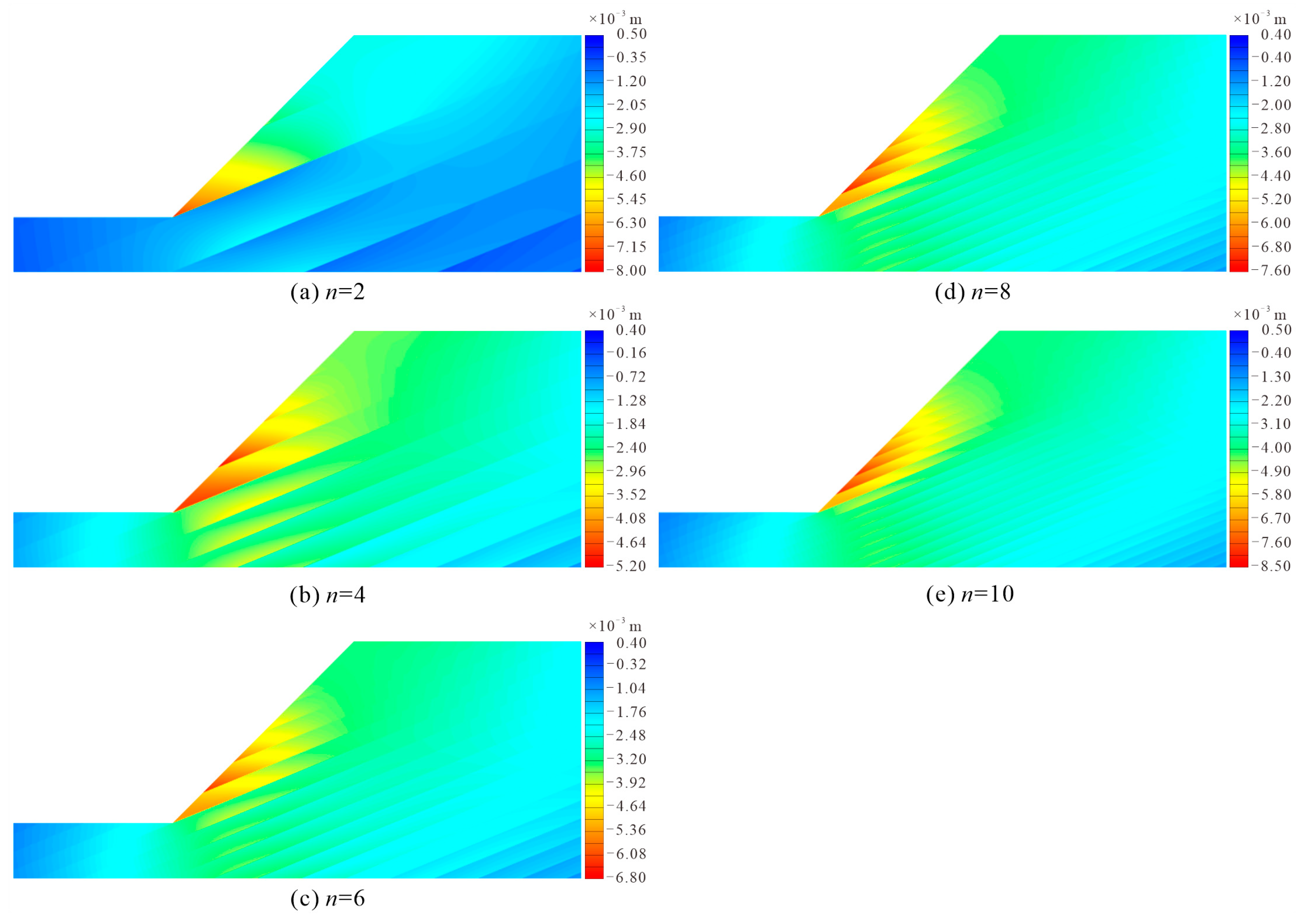
3.1. The Impact of the Number of Exposed Muddy Interlayers on the Slope Surface
The horizontal displacement clouds (
Figure 2) of the focal area of the bedding cataclastic rock slope containing multi-muddy interlayers showed the following five features: (1) The horizontal displacement of the slope was mainly negative, and only the local area was positive; (2) The absolute value of horizontal displacement near the foot of the slope was larger than that of the shoulder of the slope; (3) The absolute value of horizontal displacement of each cataclastic rock layer between the interlayer decreased gradually from the slope face to the top of the slope; (4) There were abrupt changes in the horizontal displacement clouds of the rock bodies on the upper and lower sides of the muddy interlayer, and abrupt changes from the slope face to the top of the slope became weaker and weaker, indicating that the rock bodies on both sides produced relative slip along the interlayer, and the relative slip from the proslope end of the interlayer to the top of the slope, and from the toe of the slope to the shoulder of the slope, became smaller and smaller; and (5) The maximum value of the absolute value of the horizontal displacement of the slope did not necessarily appear at the toe of the slope. When
n was one or two layers, it appeared at the toe of the slope, and when
n was more than two layers, it appeared at the position of the intersection of the second layer of the interlayer layer and the slope surface. The above analysis showed that the bedding cataclastic rock slope containing multi-muddy interlayers underwent multi-layered relative slip along the interlayer, and the relative slip gradually decreased from the toe to the top of the slope.
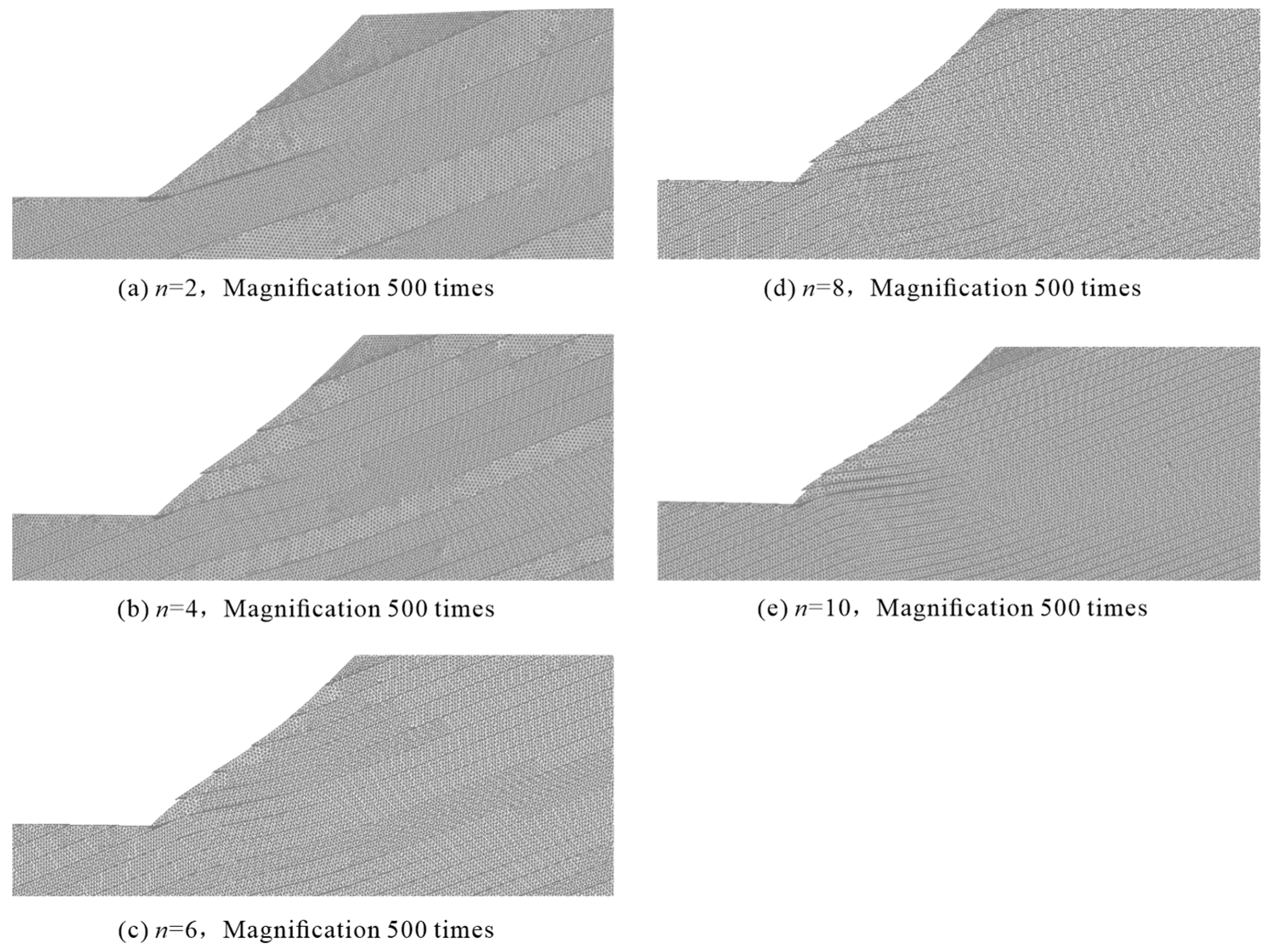
The grid deformation map (
Figure 3) showed that the muddy interlayers of each computational model showed relative slip, and the relative slip was greater for the muddy interlayers near the toe of the slope. As the number of layers of muddy interlayers increased, the thickness of the cataclastic rock layer became thinner and the slope was damaged by “sliding-bending-shearing”. A similar computational model by Zhang et al. [
12] did not show “sliding-bending-shearing” damage. This was because, in their calculation model, the elastic modulus of the surrounding rock of the weak interlayer was large (999 MPa) and the rock layer of the surrounding rock was thick, so its flexural stiffness was large and it was not easy to bend and deform under the action of extrusion. However, the surrounding rock in this study was fractured rock, whose elastic modulus was small, and the thickness of the cataclastic rock layer became thinner as the number of interlayer layers increased, and its flexural stiffness was small, and it was easy to bend and deform. On the whole, the destabilization mode of the upper part of the slope was “traction-sliding”, the destabilization mode of the rock near the toe of the slope was “sliding-bending-shearing”, and the destabilization mode of the bedding cataclastic rock slope containing multi-muddy interlayers was “traction-sliding-bending-shearing”.
Figure 4 shows the relationship among the safety factor of the slope, the maximum horizontal displacement, and the number of layers of muddy interlayers exposed on the slope. When there was no interlayer, the maximum horizontal displacement of the slope was −4.886 × 10
−5 mm; when there was only one layer of interlayer at the toe of the slope, the maximum horizontal displacement increased to −5.276 mm; when there was two layers of interlayer, the maximum horizontal displacement increased to −7.776 mm; and when there was four layers of interlayer, the maximum horizontal displacement decreased to −5.137 mm. When the interlayer increased from 4 to 10 layers, the maximum horizontal displacement slowly increased again to −8.108 mm. The maximum horizontal displacement generally increased with the number of layers of the interlayer. The slope safety factor decreased rapidly from 2.548 to 1.223 for the muddy interlayers from 0 to 1 layer, and slowly decreased to 1.202 for the increased interlayer from 1 to 10 layers. The overall safety factor decreased as the number of layers of interlayer increased, and the decisive influence on the safety factor of the slope was the muddied interlayer through the toe of the slope.
The simulation results of Zhang et al. [
12] showed that the slope safety factor first decreased rapidly and then decreased slowly as the number of soft interlayers exposed on the slope surface increased. The results of Chai et al. [
16] showed that the slope displacement slowly increased and the safety factor slowly decreased as the number of exposed interlayer layers on the slope surface increased. The results of this study were similar to those of Zhang et al. [
12].
3.2. The Impact of the Dip Angle of Muddy Interlayers
First of all, it should be noted that, when the model with slope angle
β = 60° is calculated according to the material parameters in
Table 1, when
θ is 30° or 40°, the numerical calculation cannot be carried out and the most unsafe inclination angle cannot be determined because of the poor self-stabilization of the slope. Therefore, the shear strength values of both the cataclastic rock mass and the muddy interlayers were increased by 30% (
Table 2), and then numerical calculations were performed.
The grid deformation of the bedding cataclastic rock slope containing multi-muddy interlayers, with different dips of cis-fragmented rocky slopes at slope angle
β = 30°, showed that the slope deformation damage was mainly rock bending deformation, and there was no slippage.
Figure 5 gives the grid deformation diagram of the slope when the dip angle
θ was 0°, 30°, 60°, and 90°.
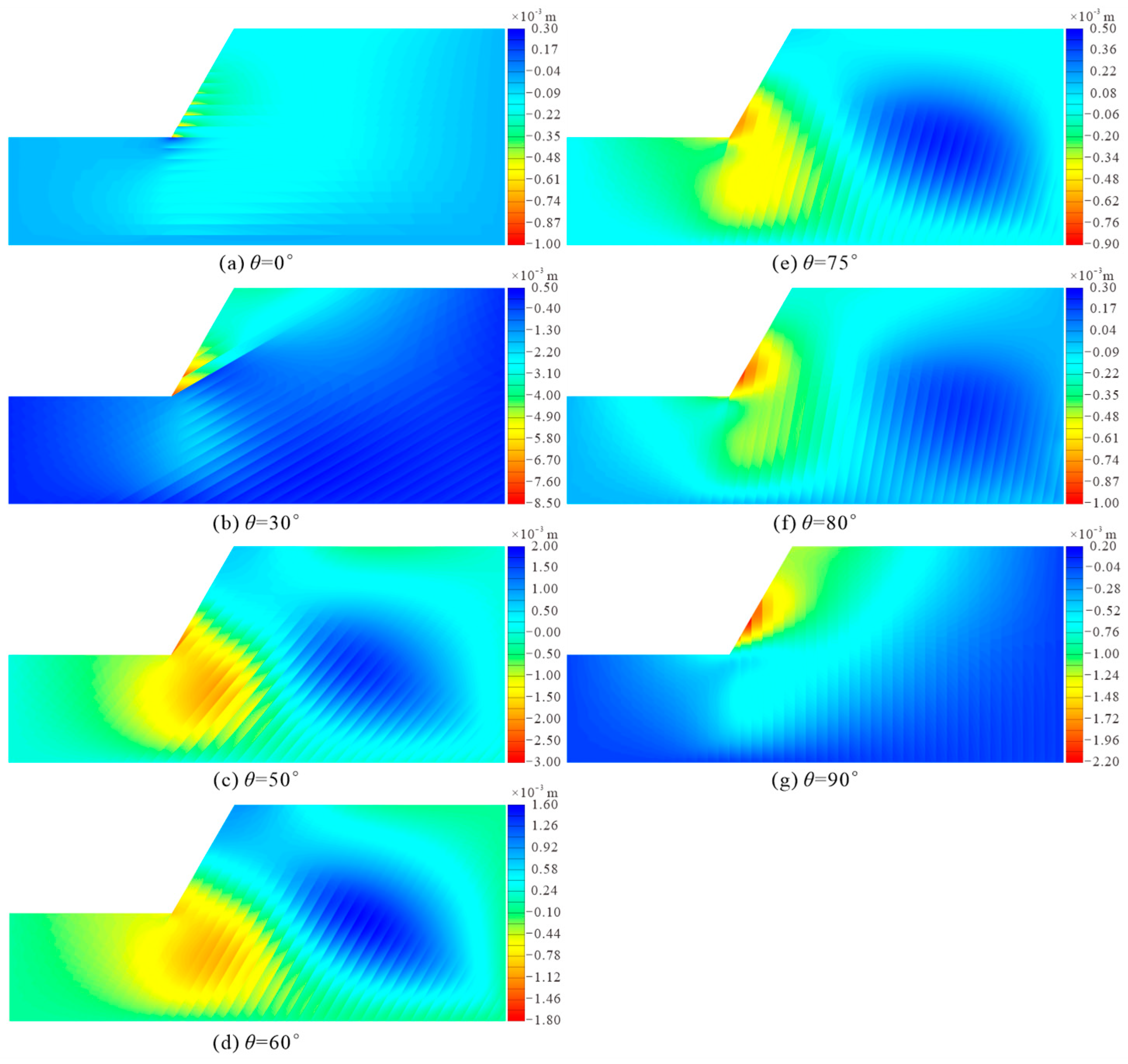
For the slope with slope angle
β = 45°, when the dip angle
θ of the muddy interlayers was 0° (
Figure 6a), the horizontal displacement of the slope was mainly negative, and the horizontal displacement had abrupt changes along the interlayer, indicating the relative slip of the rock layer. For each cataclastic rock mass, the horizontal displacement at the bottom of the layer was significantly larger than at the top of the layer, and the relative slip phenomenon became weaker and weaker from the toe to the shoulder of the slope and from the face to the inside of the slope. When the dip angle
θ of the muddied interlayer increased to 10° (
Figure 6b), the overall characteristics of the horizontal displacement diagram of the slope were not significantly different from those at 0°, excepted that the maximum value of the absolute value of horizontal displacement in the X-negative direction increased by 167%, indicating that the tendency of the slope to slide toward the prograde was enhanced.
θ increased from 10° to 45°, the number of layers of muddy interlayers exposed on the slope surface gradually decreased, and the horizontal displacement diagram of the slope showed the following three characteristics: (1) The maximum value of the absolute value of the horizontal displacement increased first and then decreased, with a maximum value at 25°; (2) The relative slip phenomenon between the layers was weak to strong and then decreased, with the most significant relative slip at 25°, the slip at 30° occurring mainly in the muddy interlayers through the toe of the slope (
Figure 6c), and basically no relative slip in the rock layers at 45° (
Figure 6d); (3) The horizontal displacement of the underlying rock layer at the toe of the slope gradually increased, and the uplift of the foot of the slope gradually became obvious.
θ increased from 45° to 80°, the dip angle of the rock layer became steeper and steeper, the self-stability of the fractured rock layer was poor, and the displacement in the X-positive direction started to appear on the shoulder of the slope, and it showed a change pattern of increasing and then decreasing. And the displacement of the toe of the slope to the X negative direction and the maximum value of its absolute value showed a trend of decreasing and then increasing (
Figure 6d–f).
θ increased from 80° to 90°, the displacement of side slope X in the positive direction decreased, the absolute value of displacement in the negative direction increased, the displacement contour was circular, and the sliding trend of the side slope toward the critical surface was more significant (
Figure 6g).
In a comprehensive analysis of horizontal displacement (
Figure 6) and grid deformation (
Figure 7) of
β = 45° slope, the slope deformation failure exhibited the following laws: (1) When
θ was 0° (horizontally bedding rock slope), the slope was compression-shear failure, i.e., under the action of its own gravity, the vertical pressure and horizontal pressure increased with depth, the compression-shear phenomenon became more obvious with increasing depth, and the shear-out displacement of the toe of the slope was the largest (
Figure 7a); (2)
θ in the range of (0°, 10°), the slope was damaged by “traction- sliding”, and the relative slip increased gradually from the shoulder to the toe of the slope, and the potential shear outlet location was the muddied interlayer through the toe of the slope (
Figure 7b); (3)
θ in the (10°, 45°) zone, the slope was damaged by “traction-sliding-bending-shear”, with uplift-bending deformation of the underlying rock layer at the toe of the slope and simultaneous slip and uplift-bending deformation of the exposed rock layer on the slope surface, especially the rock layer near the toe of the slope (
Figure 7c); (4)
θ in the range of [45°, 80°), the slope rock layer mainly deformed in flexure, the shoulder of the slope dipped and deformed towards the back of the slope, while the toe of the slope rose towards the surface (
Figure 7d). Similar to the principle of a cantilever beam, the length of the cataclastic rock layer near the toe of the slope was short and the dumping deformation toward the back of the slope was small, while the length of the cataclastic rock layer on the shoulder of the slope was long and the dumping deformation was large, so the rock layer on the slope was separated along the muddy interlayers due to uncoordinated deformation (
Figure 7e), and a tension zone was formed in the interlayer; and (5)
θ was in the interval of [80°, 90°], the slope was damaged by “bending-buckling-collapse”, i.e., by the action of the slope thrust. When
θ was 80°, the fractured rock layer at the toe of the slope was nearly upright, and the collapse may have occurred (
Figure 7f), while when
θ was 90°, the rock layer in the middle of the slope was deformed by bending, while the rock layer at the lower part (toe of the slope) was deformed by bending-buckling and collapsed to the prograde, and the tendency of the slope to collapse disaster was more obvious (
Figure 7g). In a similar computational model by Zhang et al. [
12],
θ increased from 0° to 90° and the slope damaged modes were compression-shear failure, sliding-tensioning failure, sliding-splitting failure, bending-buckling failure, and collapse failure, in that order. In contrast to their study, traction-sliding-bending-shear failure and flexural deformation also occurred in bedding cataclastic rock slope containing multi-muddy interlayers. The relationship between slope failure modes and dip angle
θ of the muddy interlayers in the rocky slopes is shown in
Figure 8.
For the slope with slope angle
β = 60°, when the dip angle
θ of the muddy interlayers was 0° (
Figure 9a), the horizontal displacement of the slope was dominated by negative values, and the horizontal displacement had abrupt changes along the interlayer, indicating the relative slip of the rock layer. For each cataclastic rock layer, the horizontal displacement at the bottom of the layer was significantly larger than at the top of the layer, and the relative slip phenomenon became weaker and weaker from the toe to the shoulder of the slope and from the face to the inside of the slope.
θ increased from 0° to 50°, the number of layers of the exposed interlayer on the slope surface gradually decreased, and the horizontal displacement diagram of the slope exhibited the following two characteristics: (1) The maximum value of the absolute value of the horizontal displacement increased first and then decreased, with a maximum value at 40°; and (2) The relative slip phenomenon was weak to strong and then weakened, with the most significant relative slip phenomenon at 30° (
Figure 9b), slip above 40° occurring mainly in the muddy interlayers through the toe of the slope, and slip weakening at 50° (
Figure 9c).
θ increased from 50° to 80°, the dip angle of the rock layer became steeper and steeper, the self-stability of the cataclastic rock layer was poor, and the displacement of the shoulder of the slope starts to appear in the X-positive direction, while the displacement of the toe of the slope went in the X-negative direction, and the maximum value of its absolute value showed a trend of first decreasing and then increasing (
Figure 9d–f).
θ increased from 80° to 90°, the absolute value of displacement in the negative direction of the slope increased, the displacement contour was circular, and the trend of sliding of the slope became more significant (
Figure 9g).
In a comprehensive analysis of horizontal displacement (
Figure 9) and grid deformation (
Figure 10) of
β = 60° slope, the slope deformation damage exhibited the following laws: (1) When
θ was 0° (horizontally bedding rocky slope), the slope was “compression-shear” failure (
Figure 10a); (2)
θ in the range of (0°, 50°), the slope was “traction-sliding” failure (
Figure 10b,c); (3)
θ in the range of (50°, 80°), the slope rock mainly deformed in deflection (
Figure 10d–f); and (4)
θ in the (80°, 90°) zone, “bending-buckling-collapse” failure occurred on the slope (
Figure 10g). Compared with the slope with
β = 45°, the slope with
β = 60° had no “traction-sliding-bending-shear” failure.
The relationship between the maximum horizontal displacement in the X-negative direction of the slope and the inclination angle
θ of the interlayer is given in
Figure 11, which shows the following five features: (1)
θ increased from 0° to 90°, the horizontal displacements of the bedding cataclastic rock slope of the four calculation schemes showed the same pattern of change, i.e., first increasing, then decreasing, then increasing; (2)
β = 30°, the
θ of the horizontal displacement maximum was 30°,
β = 45°, the
θ of the horizontal displacement maximum was 25°, and
β = 60° (30% increase in strength), the
θ of the horizontal displacement maximum was 40°; (3) The horizontal displacement of upright laminated slopes was greater than that of the horizontally laminated slopes; (4) Overall, the horizontal displacement of steeply bedding rock slope was smaller than that of gently bedding rock slope; and (5) The slope angle
β increased and the horizontal displacement increased.
The relationship between the slope safety factor and the dip angle
θ of the mezzanine is given in
Figure 12, which shows the following five features: (1)
θ increased from 0° to 90°, the safety coefficients of the four calculation schemes showed the same pattern of change, i.e., first decreasing, then increasing, then decreasing; (2)
θ for the minimal value of safety factor was 20° when
β = 30°,
θ for the minimal value of safety factor was 30° when
β = 45°, and
θ for the minimal value of safety factor was 40° when
β = 60° (30% increase in strength); (3) The safety factor of upright bedding slope was slightly greater than that of horizontal bedding slope; (4) In general, the safety factor of steeply bedding rock slope was greater than that of gently bedding rock slope; and (5) The safety factor decreased as the slope angle
β increased, and the
θ corresponding to the very small value of the safety factor increased. The above conclusions are consistent with Zhang et al. [
12].
For rocky slopes containing a single layer of muddy interlayers, Lu [
13] concluded that
β = 75° and
θ increased from 25° to 60°, the horizontal displacement increased and then decreased, and the safety factor decreased and then increased. The results of Liu et al. [
17] showed that
β = 45°,
θ increased from 30° to 39°, and the horizontal displacement increased. According to Lu [
13],
θ for the extreme value of horizontal displacement was 45° and
θ for the very small value of safety factor was also 45°, which was larger than
β = 60° determined in this study when
θ was both 40°. This was because the analytical model
β = 75° of Lu [
13] was larger than this study. Although the above laws are obtained based on the bedding rock slope containing a single soft interlayer, they coincide with the bedding cataclastic rock slope containing multi-muddy interlayers studied in this chapter in the corresponding range of dip and slope angles. However, their study also reached different conclusions from this chapter, for example, Liu et al. [
17] showed that the safety factor decreased when
θ increased from 30° to 39°.
3.4. The Influence of the Internal Friction Angle of the Muddy Interlayers
Similarly to the influence of the cohesion
c of the muddy interlayers, the stress concentration phenomenon of maximum principal stress and maximum shear stress in the slope was weakened by increasing the angle of internal friction angle
φ, the stress contour became smoother and smoother, and the maximum shear strain gradually decreased. The horizontal displacement diagram of the slope (
Figure 18) exhibited the following characteristics: (1) Horizontal displacement was mainly in the X negative direction, the angle of internal friction angle
φ increased, the maximum value of the absolute value of horizontal displacement gradually decreased, and the maximum position was always in the second layer of the mezzanine; and (2) When
φ decreased, the sudden change in displacement between the exposed rock layers on the slope surface and between the underlying rock layers on the slope body was not strong, but the sudden change in displacement between the exposed rock layers on the slope surface and the underlying rock layers on the slope body was strong. When
φ increased, the displacement mutation between the exposed rock layers on the slope surface and between the underlying rock layers on the slope body was enhanced, but the displacement mutation between the exposed rock layers on the slope surface and the underlying rock layers on the slope body was weakened. There was no uniform law on the influence of
φ on the slope deformation damage law, as shown in
Figure 18. When
φ was 8°, the slope showed traction-slip damage (
Figure 19a), when
φ increased to 14°, the slope showed traction-sliding-bending-shear failure (
Figure 19b), when
φ increased to 20°, the slope was again traction-slip damage (
Figure 19c), and when
φ increased to 24°, the slope again showed traction-sliding-bending-shear failure (
Figure 19d).
Figure 20 shows that the internal friction angle
φ of the muddy interlayers increased from 8° to 30°, and the maximum horizontal displacement first decreased rapidly, then decreased slowly and tended to 0. The slope safety factor increased linearly from 0.89 to 1.83, and the slope stability gradually improved.
For bedding rock slope containing a single soft interlayer, the analytical models of Zhang [
14] and Qin [
15] were
H = 50 m,
β = 60°,
θ = 50°,
c = 0.046 MPa, and
φ = 15° to 30°. The numerical model of Liu et al. [
17] was
H = 50 m,
β = 45°,
θ = 39°,
c = 0.025 MPa, and
φ = 10°~25°, and they argued that the displacement of the slope first decreased rapidly and then decreased slowly as
φ increased, and the safety factor increased linearly, while, in the calculation model of Lu [
13],
H = 50 m,
β = 60°,
θ = 45°,
c = 0.046 MPa,
φ = 20°~35°, they considered that
φ increased, the slope displacement decreased first and then increased, and the safety factor increased first and then decreased.
Differing from the results in the above literature, this paper argued that the internal friction angle of the soft interlayer increased the overall slope displacement when it exceeded the internal friction angle of the interbedded surrounding rock, which was not conducive to rock stability. In order to verify this explanation, the internal friction angle of the muddied interlayer of the model calculated in this section was increased to 30°, and no slope displacement and safety factor reduction occurred.


