Abstract
The broad acceptance of electromobility depends heavily on the performance and service life of the battery technology used. Lithium-ion battery technology is currently the most promising energy storage technology for mobile applications, but the performance and capacity of the cells are extremely temperature sensitive. Especially in these new complex and powerful applications, there is a significant need for thermal management. Depending on the ambient conditions, part of the effective battery energy must, therefore, be used to temper the system. So far, mainly active components have been used for this task. This not only reduces the overall efficiency but also increases the weight, volume, and maintenance requirements of the system. In the present work, an alternative battery temperature management system was developed. A concept based on latent heat storage materials was created, which uses the advantages of thermal energy storage and the design freedom of additive manufacturing technology, and its suitability for use in battery applications was checked. On the one hand, the use of systems for storing thermal energy was researched and, on the other hand, an innovative cooling concept was created considering new production possibilities.
1. Introduction
Widespread acceptance of electromobility is highly dependent on the performance and service life of the battery technology used. Lithium-ion batteries (LIB) are currently the most promising energy storage technology for mobile applications available, but cell performance and capacity are greatly affected by environmental conditions, especially temperature [1]. Winter temperatures reduce the energy efficiency and practical energy availability of lithium-ion battery packs by up to 30%. The charging characteristics of many lithium-ion technologies generally do not allow discharging at excessively high temperatures. In addition, freezing temperatures often prevent charging. By maintaining a defined temperature range of at least 15 °C up to 30 °C, these drawbacks can be greatly reduced and even eliminated [1]. With this technology, battery temperature becomes a key parameter for battery performance. Also, batteries generate a lot of heat during charging and discharging and must be dissipated by proper cooling. Heating is also required when the vehicle is operated in cold temperatures. The possibility of storing thermal energy in battery packs is being explored for more efficient use of energy. The advantage of storing waste heat in the battery system lies in user behaviour and the system-related fact that the vehicle is not always connected to a charging station in order to generate the energy to heat the battery pack. Maintaining a traction battery temperature window not only optimizes performance and storage capacity but also reduces the load on the battery cells, which has a positive effect on service life. This reduces the total energy consumption of electric vehicles in their lifecycle from production to recycling. This alleviates the weaknesses of LIB, which are reduced performance and storage capacity at low temperatures. Phase change materials (PCM) offer the potential to store thermal energy with high energy densities. Our goal was to integrate such a PCM into the battery box. The manufacturing options examined are metal 3D printing. This field of additive manufacturing technology makes it possible to produce parts that could not be manufactured in the past. This allows to optimally implement an innovative heat transfer system inside the battery pack for the first time. The new system can keep all battery cells at a uniform temperature throughout the battery pack. The purpose of thermal management is to keep the inside of the box within a defined temperature window to ensure the safe, long-lasting, and efficient operation of the battery cells.
2. Materials and Methods
The system components of a battery temperature management system (BTMS) have been identified and found to be suitable candidates for energy-efficient energy storage systems for electric vehicles. LIB thermal parameters are defined. Based on the parameters of the battery cells used, a suitable PCM was defined, and its suitability was tested in laboratory experiments. To verify the properties of PCMs, a test bench has been developed that can automatically measure different PCMs simultaneously. Furthermore, PCM can be observed over longer periods of time. The developed PCM test stand has a mobile and modular design, allowing the specimen to be exchanged and the heat accumulator to be expanded. Particular attention was paid to additive manufacturing options when designing the battery pack. Aspects such as component geometry, component thickness, overhangs and supports, post-processing processes, material selection, and manufacturing costs must be considered. A computational fluid dynamics (CFD) model was created and simulated to describe the thermal behaviour of a battery system with cooling or heating integrated with PCM storage. This simulation can be used to test different scenarios and explore the thermal behaviour of components under different conditions, such as different temperatures and load conditions.
2.1. PCM Enhanced Battery Packs
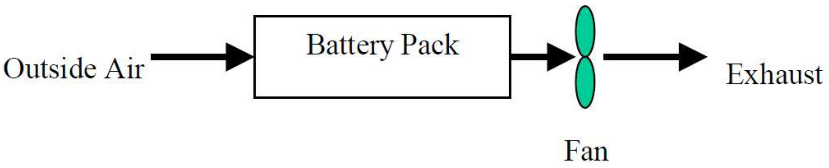
In all climes, a BTMS in an electric vehicle is required for the proper operation of a traction battery. The primary purpose of this system is to maintain the battery at an optimal average temperature range. It must meet the car manufacturer’s specifications. This would be a small and lightweight design that is economical, dependable, easy to maintain, and uses little parasitic power. A BTMS can be passive or active, and it can use air or liquid for cooling and heating [2]. Due to cost, size, and space constraints, as well as their use in warm regions, early car battery packs did not use heating or cooling devices, instead relying on ambient air blowing in to remove heat from the batteries as shown in Figure 1.
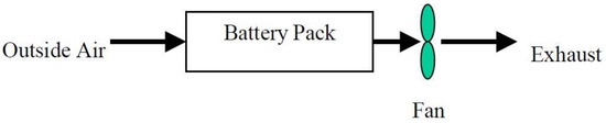
Figure 1.
Passive cooling with ambient air [2].
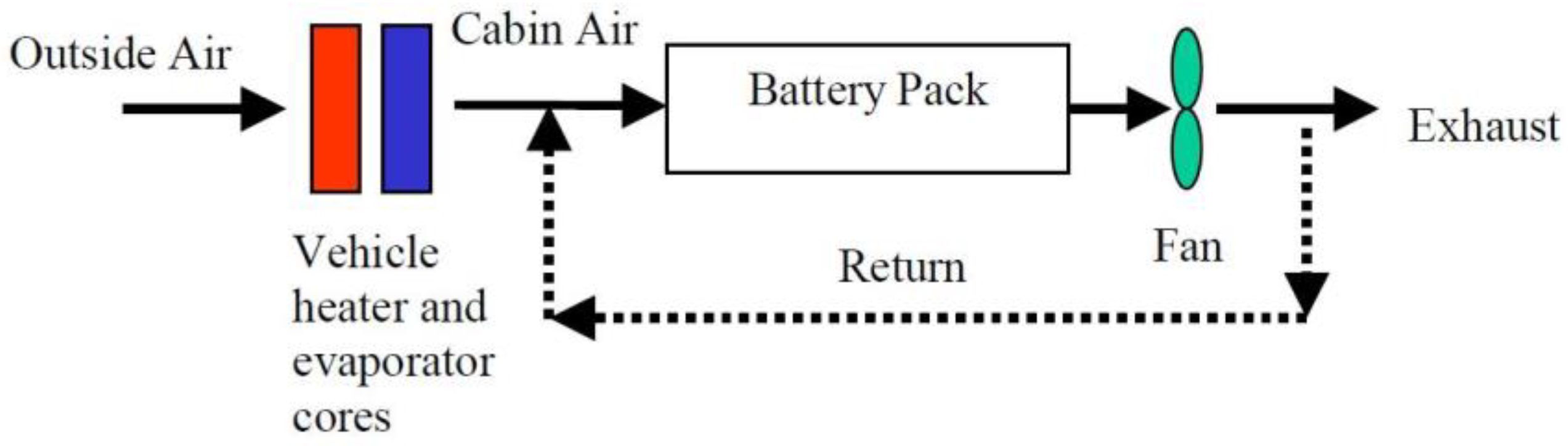
The first prototypes used passive ambient air cooling. Cabin air is used today to cool/heat the packages as shown in Figure 2 and Figure 3. Although the ambient air is heated and cooled by the vehicle’s air conditioning or heating system, it is still considered a passive system [2].

Figure 2.
Passive heating and cooling with cabin air [2].

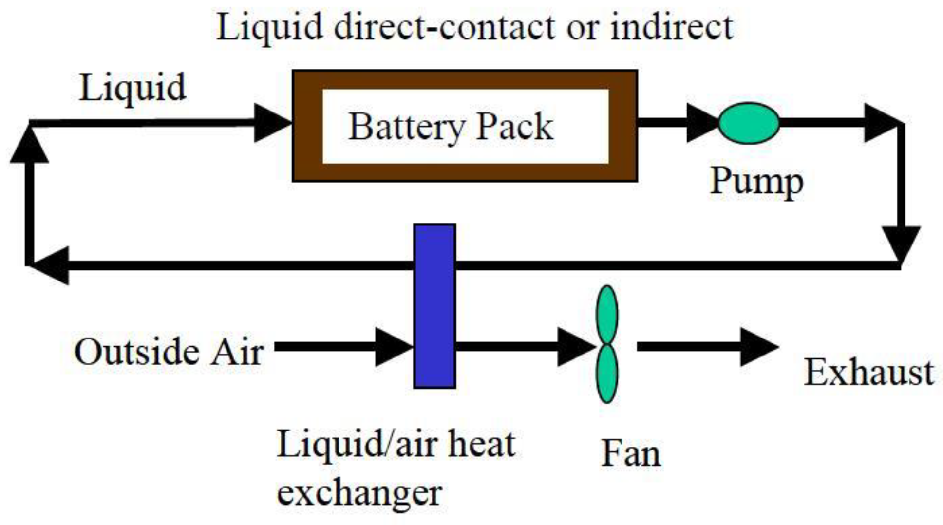
Figure 3.
Passive cooling with liquid circulation [2].
For these passive systems to function successfully, the ambient air temperature must be between 10 °C and 35 °C. Otherwise, the package’s performance will decrease in extreme cold or heat. Active components such as evaporators, heater cores, engine coolants, and even electric and fuel-fired heaters are required outside of these limits [2].
For thermal management of electric vehicles, common heat dissipation techniques including forced air cooling and liquid cooling are frequently employed. Such BTMS first seem to be highly effective, but they often increase the overall system’s weight and parasitic power requirements by adding extra blowers, fans, pumps, pipes, and other accessories that are large, expensive, and complex [2]. These cooling system limitations, the increased energy consumption of parasitic loads, and the limited battery capacity can all be avoided by using a well-designed and optimized PCM system [3]. Many advantages can result from a novel thermal management approach that uses PCM as a heat dissipation source. A compact, cost-effective, and warp-resistant system without ancillary performance requirements ought to be the primary benefit of such a heat management system [3].
2.1.1. Phase Change Material
Heat is stored in sensitive heat storage materials by the temperature difference between the storage medium before and after the charging process. Temperature difference, heat capacity, and storage medium mass all play a role in the amount of energy stored. Sensitive heat storage systems, which can be found in almost every household as a warmwater tank and a buffer storage require good heat insulation.
PCM—heat storage systems are also known as latent heat storage because the heat is stored more latently than sensible in a PCM. The charging and discharging are accomplished by changing the aggregate state of the medium based on its respective enthalpy. These systems can store heat relatively lossless over long periods of time [4].
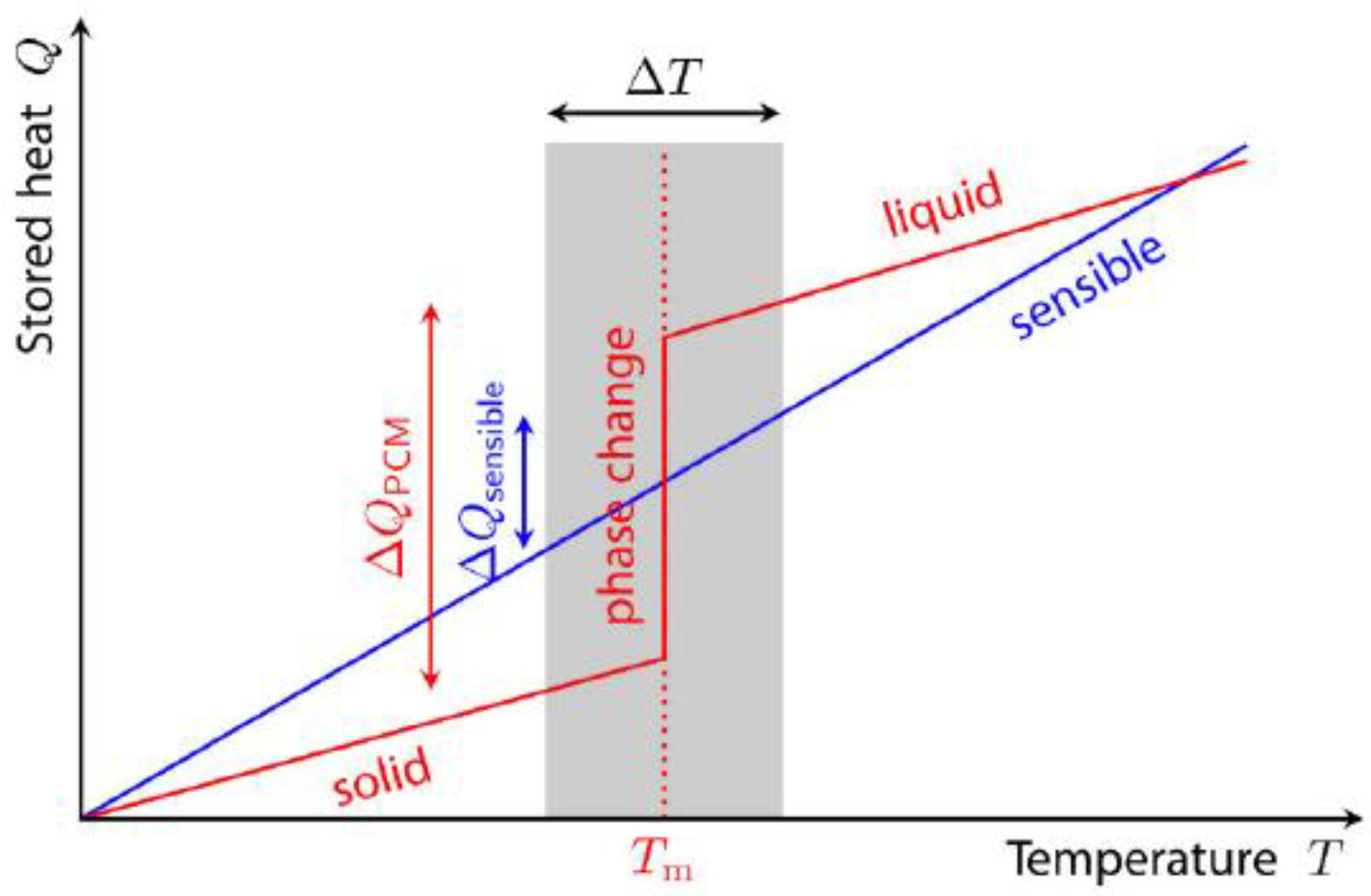
Figure 4 depicts the distinction between sensible and latent heat storage. The benefit of larger energy storage amount is limited to a certain temperature range. The solid–liquid phase transition and vice versa is the most widely employed principle. Special salts or paraffin are frequently melted as a storage medium for charging the storage, as they absorb a lot of thermal energy. The discharge happens as the storage medium solidifies, releasing the previously absorbed massive amount of heat back into the environment as solidification heat. The amount of heat depends not only on the system’s temperature difference but also on the material’s mass and specific heat capacity. Table 1 shows the specific heat capacities of some substances. Since mass is not the only determinant of energy storage, consistency, and volumetric heat capacity are often also specified. The heat capacity of a material indicates how much heat it can store in 1 m3 when the temperature is increased by 1 K [4].
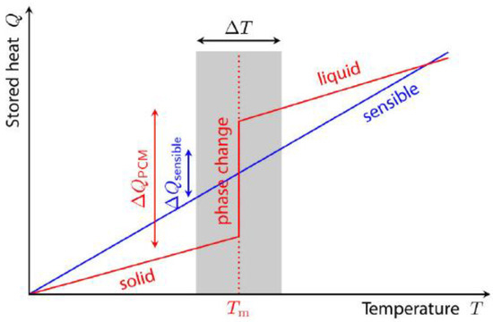
Figure 4.
Stored heat temperature—diagram [5].

Table 1.
Heat Capacity of Materials [4].
Different material classes are used as latent heat storage, depending on the temperature range. Solid–liquid transition is mainly used because the volume change is easier to handle than solid–liquid transition and the enthalpy of the transition is sufficiently high compared to solid–liquid transition. The longest and most commonly used PCM is water or ice. It meets all the required standards and is very cheap and available everywhere. In addition to water, the substance classes salt hydrates and paraffins are most frequently used [5]. Therefore, the application determines the storage medium with the optimum phase transition temperature. Water and salt solutions are primarily used for refrigerated storage. There are various materials that are suitable for phase change heat storage. In practice, solid-to-liquid transitions are mostly used. A phase change from liquid to gas is avoided despite the high phase transition enthalpy due to the large change in volume [4]. Salts such as nitrates, chlorides, carbonates, and fluorides are mainly used for heat storage above 130 °C, but mixtures of these substances are also used at these temperatures. The use of salt hydrates as PCMs results in so-called discordant melting [6], which affects the reversibility of the phase change process and thus reduces the heat storage capacity of the medium. By adding suitable additives to salt hydrates in pure form, it is possible to counteract the phenomenon of incompatible melting and use the medium in a temperature range of around 100 °C [6]. The paraffin-based PCMs are characterized by being particularly harmoniously soluble, cycle-resistant, ecologically harmless, harmless to health, and not corroding metal building materials [5]. Special attention should be paid to the phase change temperature, as it is the most important criterion in selecting a PCM for a particular application. The energy density and temperature range of the most popular PCMs are depicted in Figure 5. No single material has all the properties needed for an ideal PCM. Therefore, available materials must be selected, and additional additives added to replace poor physical properties with suitable system designs [6]. The selection of suitable PCMs for passive BTMS was determined by the materials available on the market and the phase transition temperature chosen.
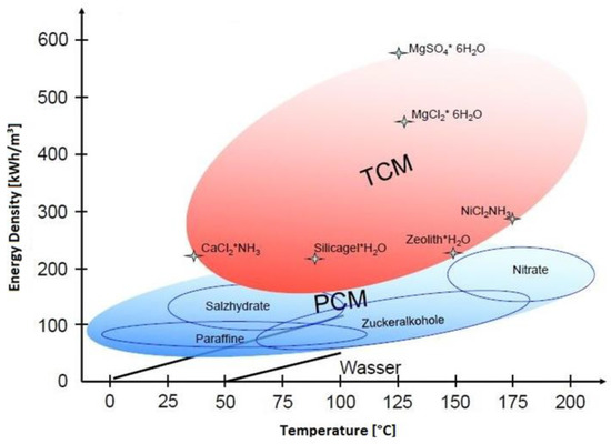
Figure 5.
Energy densities of different materials [5].
2.1.2. PCM Preselection
The pre-set battery technology defines an ideal temperature range for continuous battery operation between 15 °C and 30 °C. Figure 5 shows that only paraffins are in question for this temperature range. For these reasons, we have chosen paraffin RT21 for our application. This material’s highest heat storage capacity is attained at temperatures ranging from 13 °C to 28 °C. Heat is stored in this area as a combination of latent and sensible heat.
This material has a heat storage capacity of 43 Wh/kg in the given temperature range, as shown in the accompanying data sheet in Table 2. In order to store the entire energy content of a battery cell as thermal energy in the PCM, 0.20 kg of paraffin RT21 per battery cell is required [7].
Table 2.
Data Sheet RT21 [8].
2.2. Metal 3D Printing
A temperature management system with an implemented cooling circuit requires a manufacturing process that enables the fabrication of complex and fragile structures. In addition, a heat-resistant material is required to withstand temperature fluctuations within or around the system. Therefore, Direct Metal Laser Sintering (DMLS) is selected to be a suitable manufacturing technology for this application. DMLS is an additive manufacturing technology for fabricating metal components out of powder particles and it is assigned to the Laser Powder Bed Fusion (LPBF) technology.
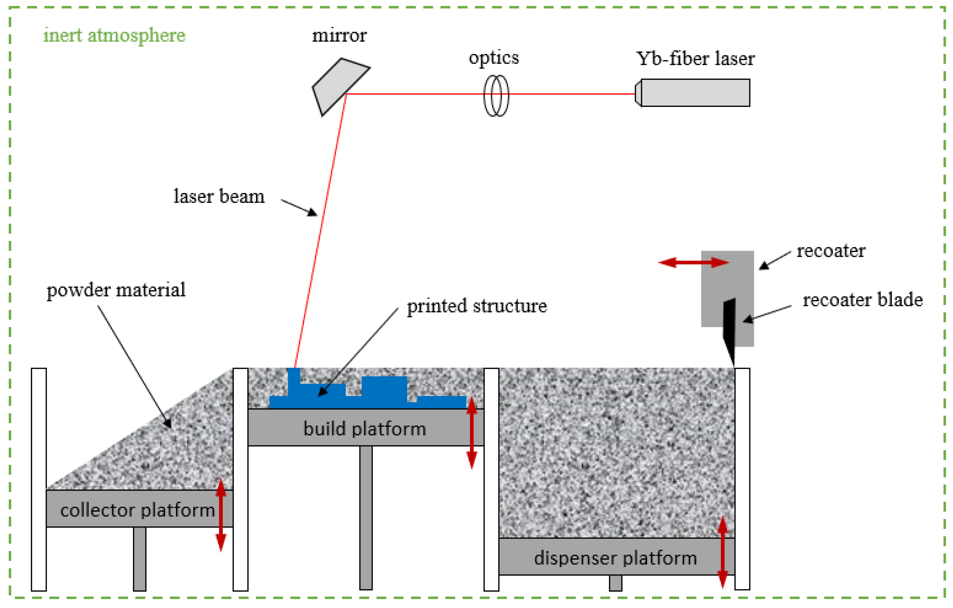
The DMLS printing system consists of three different chambers as schematically shown in Figure 6. These chambers are flooded with inert gas (Nitrogen/Argon—depending on the powder material) to create an oxygen-free atmosphere during the printing process. There is one movable platform in each of the chambers. First, the powder material is filled on the dispenser platform. Here, the powder material must be manually compacted with the help of spatulas to avoid cavities that could lead to problems during the print job. Then, the recoater arm including the recoater blade moves across all three platforms, starting on the right (dispenser platform). Here, the recoater blade (steel, ceramic, or soft brush—depending on the powder material and on the geometry) takes away a certain amount of powder material which is then applied on the build platform. The excessive powder material is pushed onto the collector platform. After the first layer of powder material is applied, a high-power Ytterbium fibre laser beam fuses the individual powder particles together according to a two-dimensional section of the computer-aided design (CAD) model. Splashes from the laser beam are blown away by a continuous gas flow across the build platform. After the powder layer is exposed, the next powder layer is applied by the recoater arm. This iterative process lasts until the structure to be printed is finished [9,10,11,12,13].

Figure 6.
Principle of DMLS printing system [14].
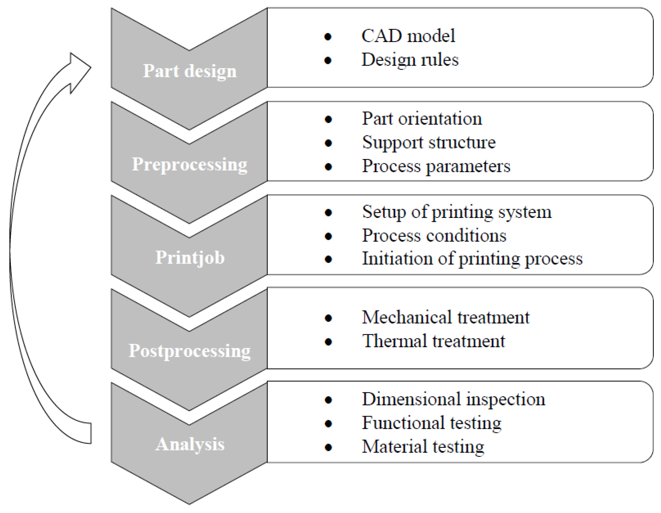
Due to the high process complexity of DMLS, the number of influencing factors (e.g., direction of the gas flow and direction/movement of the recoater arm) can have a significant impact on the buildability, the quality, and also the process costs. To keep the risk of adverse effects from influencing factors low, the entire printing process should be considered, including the individual steps as shown in Figure 7.
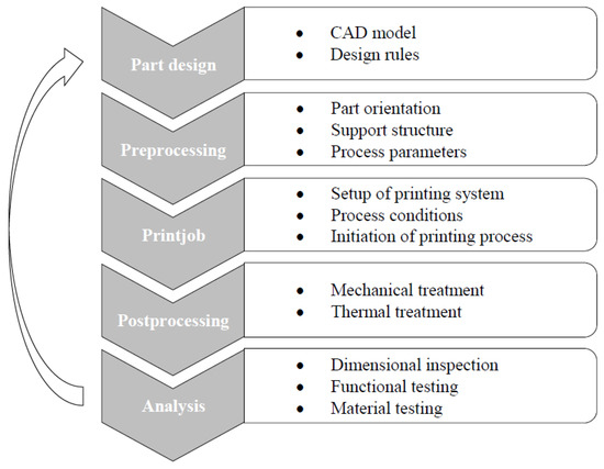
Figure 7.
Iterative development for the fabrication of parts via DMLS [14].
The first step in the printing process is part design. A 3D model of the component is created using CAD software, considering process and material-dependent design guidelines. These design guidelines contain relevant information regarding geometric constraints (maximum pin diameter, minimum wall thickness, etc.). A well-thought-out design saves support structures and helps reduce process costs. This step has been given special attention and is described in more detail in Section 2.3. At the end of the part design, the 3D model is transferred into a standard transformation language (STL) file.
The second step is called pre-processing. In this step, the STL file is loaded into software that represents a virtual build platform (e.g., Materialize Magics). This is where the part orientation is defined, and the support structure is generated. Part orientation has a significant impact on part quality and process costs. After this step, the STL files are transferred to the slicing software (e.g., EOSPRINT). Within the slicing software, the 3D model in the STL file is divided into 2D sections, so-called ‘slices’. This step is necessary because the printing system processes one layer at a time during the process. Additionally, appropriate printing parameters are selected in the slicing software. Each powder material requires specific printing parameters that guarantee the maximum density and strength of the part. Nevertheless, depending on the application and part geometry, it is also possible to change some process parameters such as laser power, laser speed, and hatch spacing to avoid problems. As soon as the pre-processing steps are completed, the virtual print job is sent to the printing system.
The third step, the print job, prepares the printing system for the next process. This step involves setting up the printing system including loading the powder material, applying the first layer of powder, cleaning the lens, and starting the process conditions. When the print job is complete, the excess powder material is cleaned off and the construction platform containing the printed structure is removed from the printer. The fourth step is post-processing. Parts are removed from the construction platform using various techniques. In addition, mechanical and thermal treatments are performed in this step. In general, DMLS-manufactured parts can be processed in any type of manufacturing process, just like conventional parts.
The fifth step in the process is Analysis. Dimensional, functional, and material checks are part of this step. The process steps in Figure 7 influence each other and affects the final result of the print job. Technical and economic aspects depend on the optimal interaction of the individual process steps. Therefore, several iterations of the entire development process may be required until optimal results are achieved.
2.3. Special Aspects of Component Design
This chapter describes in more detail the aspects to be considered in the design process of the battery pack. In addition to the heat storage capacity and the heat conduction in the package, the main aspects here were also the integration of a cooling component and the special manufacturing guidelines of 3D printing. In Section 2.1.2, we have already established that 0.20 kg of paraffin RT21 per battery cell is required to accommodate the entire energy of the LIB in the PCM. The battery concept allows for additional external heating or cooling, and in order to keep the size and weight of the battery pack within normal limits, the amount of heat storage mass was reduced to 0.05 kg/cell. Furthermore, the aspects of the component design depend on the appropriate printing system. In our case, we decided to use the EOS M400 printing system. The aspects are
- Minimum wall thickness: 0.4 mm
- Minimum cavities: 0.8 mm
- Minimum distance from wall to wall: 0.4 mm
- Minimum angle for overhangs: 45°
The thickness of the walls in the construction is between 0.5–2 mm. The diameter of the pipes is 3.1 mm. The distance between the edge of the honeycomb is 4 mm. Inside the box we have designed a honeycomb structure. The upper and lower part of each honeycomb is a hemispheres so we do not need any additional support structures inside.
2.4. Design, Modeling and Simulation
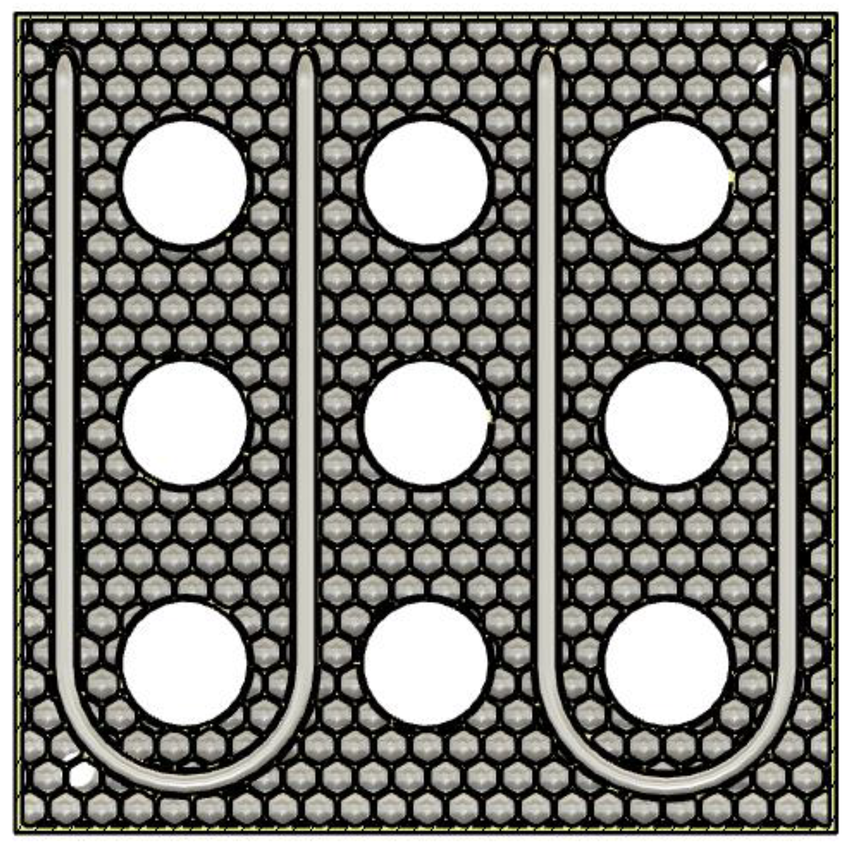
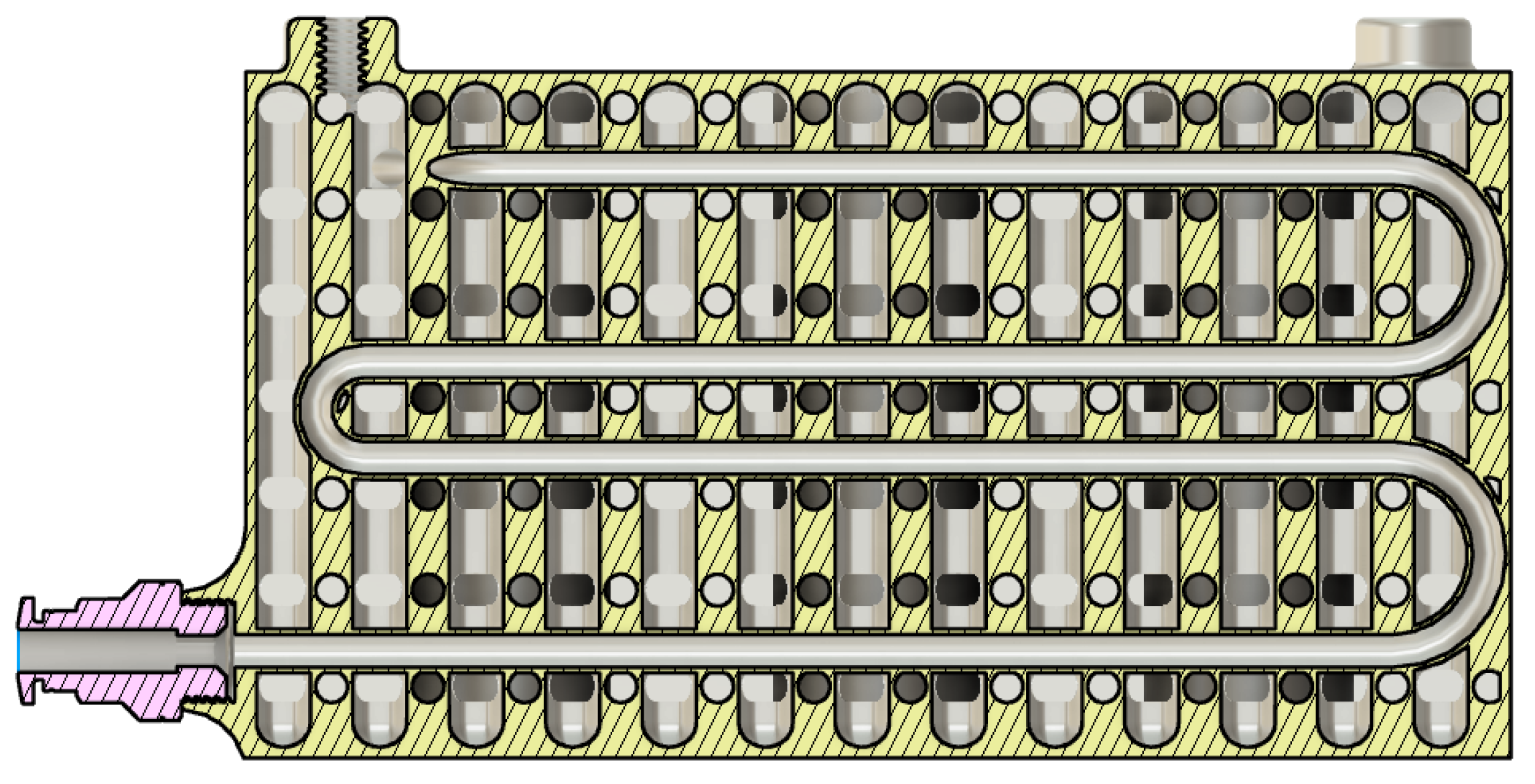
To assess the feasibility and functionality of BTMS, the development process is supported by simulations. In today’s industry, simulation is an everyday tool, especially in companies with strong engineering ties, such as the automotive industry or mechanical and plant engineering. Therefore, in science as well as in business, there is a strong demand for ways to utilize computers to provide competitive and functional products and to manufacture and sell them efficiently, with high quality and safety [15]. Computational fluid dynamics (CFD) is a computational mathematical modelling tool that can be viewed as a fusion of theory and experiment in the fields of fluid flow and heat transfer. CFD simulations provide information about flow and fluid properties that can be difficult or expensive to obtain by measurement, providing insight and understanding of product performance or flow behaviour in specific situations. CFD is now used in many industries, starting from aerospace and power generation to consumer goods, biomedical, pharmaceutical, built environment, and many more. Where CFD has historically been used to predict or understand the flow performance of existing designs or conditions. The most effective and productive usage is achieved when applied early in the design process to drive the design towards better or more consistent performance [16]. Even the simplest heat exchange system is actually quite complex when viewed through rigorous analysis. Therefore, we decided to perform flow analysis in BTMS using a computational fluid dynamics software tool that offers 3D flow analysis. CFD is a software tool for simulating the behaviour of systems involving fluid flow, heat transfer, and other similar physical processes. It solves the equations of fluid flow over a defined region. The specified conditions on the boundary of that region must be known. Creating such CFD models and analysing the results is quick and easy thanks to advanced computing power, powerful graphics and interactive 3D manipulation of the models. Advanced solvers contain algorithms that provide robust solutions to flow fields in a reasonable amount of time. For these reasons, CFD is now an established industrial design tool that offers a cost-effective and accurate alternative to scale model testing. Various solutions are used in CFD codes, the most common is known as the finite volume technique. In this technique, the region of interest is divided into smaller sub-regions called control volumes. The equations are discretized and solved iteratively for each control volume. As a result, an approximation of the value of each variable can be obtained at specific points throughout the domain and we get a full picture of flow behaviour. The estimation of the heat dissipation of solids by convection can be made only by an abstraction of the considered body to very simple geometries. However, these empirical approximations lose their meaning when the geometry of the object and the abstraction diverge significantly. Heat sources with very complex shapes cannot be meaningfully represented by abstractions and the Heat output can only be calculated under very simple conditions. In order to make statements about the thermal behaviour of battery systems with passive PCM cooling, CFD models of batteries, and surrounding thermal mass have been created. The CFD tool Autodesk CFD 2023 was used for this. In the passive BTMS, the heat generated within the battery cells of a battery pack should be transferred to the PCM. The generated heat is stored in the PCM and provides an ideal temperature range for the battery cells. In Section 2.3, we clarify how we will construct a structure so that we do not require a support structure given by the slicer. The other two basic focuses are cooling or heating and PCM space. We design channels inside the structure for cooling and heating. The honeycomb construction also serves as a support framework for the channels as can be seen in Figure 8. Figure 9 appears the penetrating through the structure. These cavity connections serve to ensure even distribution of the PCM. The middle section of the construction was simulated in Autodesk CFD 2023 to generate preliminary estimations of the temperature distribution. The battery slot’s wall temperature was anticipated to be 30 °C. The liquid passing through was supposed to be 10 °C in temperature. A cooling water speed of 2 m/s, an ambient temperature of 20 °C, and a starting temperature for the PCM of 20 °C were specified as additional boundary conditions. The PCM material was determined via its specific heat characteristics depending on the volume change between the solid and liquid phases. The PCM was simulated using its specific heat capacity in relation to mass and temperature. The values shown in Table 3 are based on the three-layer calorimeter measurement from the data sheet of RT21 as can be seen in Figure 10.
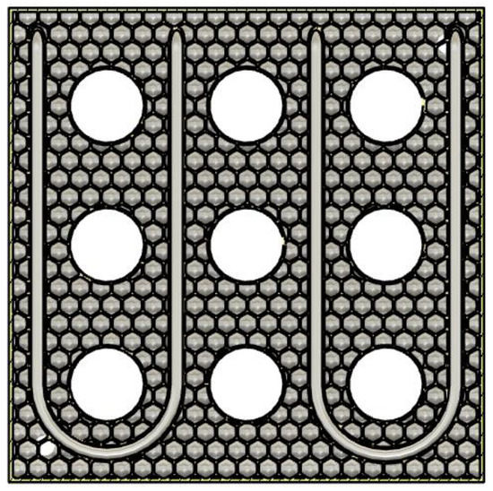
Figure 8.
Honeycomb structure inside the pack.
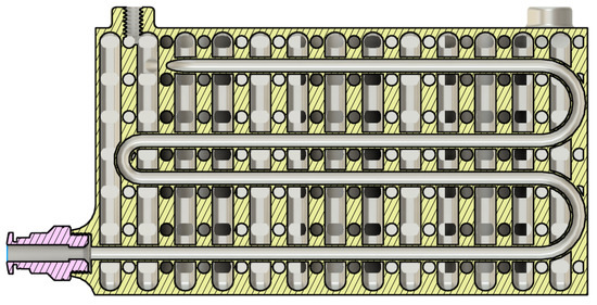
Figure 9.
Hemisphere from upper and lower part.
Table 3.
Partial Enthalpy and Specific Heat over Temperature and Mass.
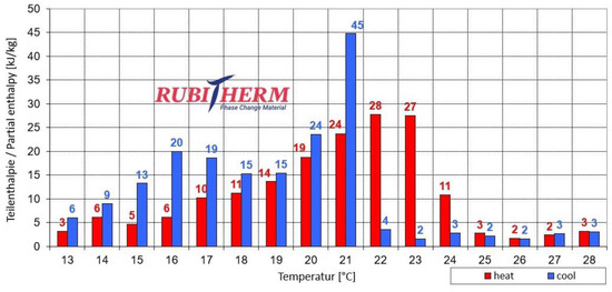
Figure 10.
RT 21 Partial enthalpy distribution [8].
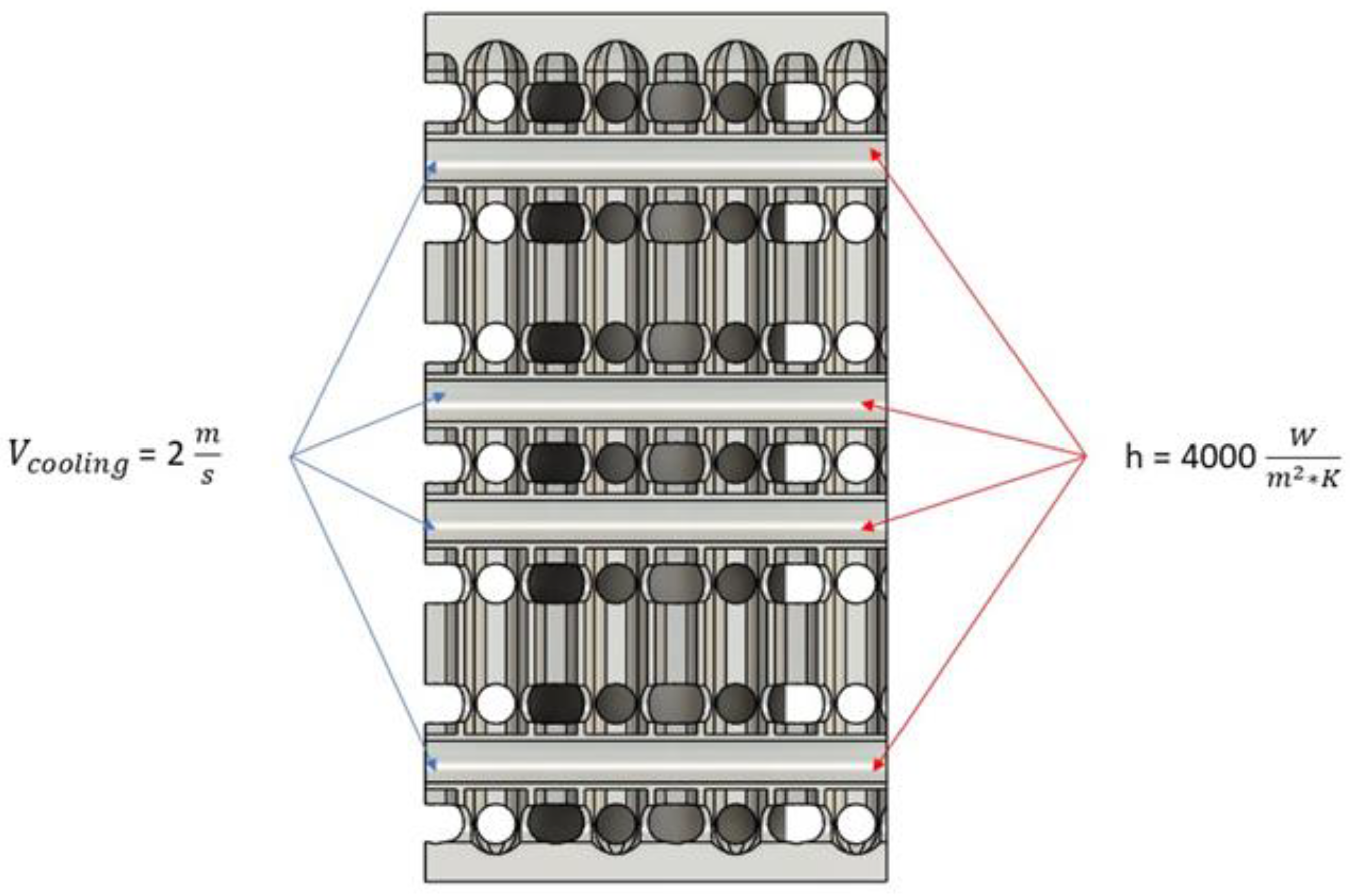
In the simulation, a heat transfer coefficient between the cooling lines and the PCM of 4000 W/m2K is assumed, as can be seen in Figure 11.
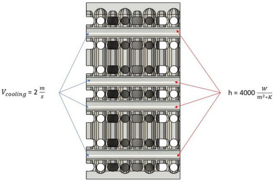
Figure 11.
Heat transfer coefficient and flow rate of cooling water.
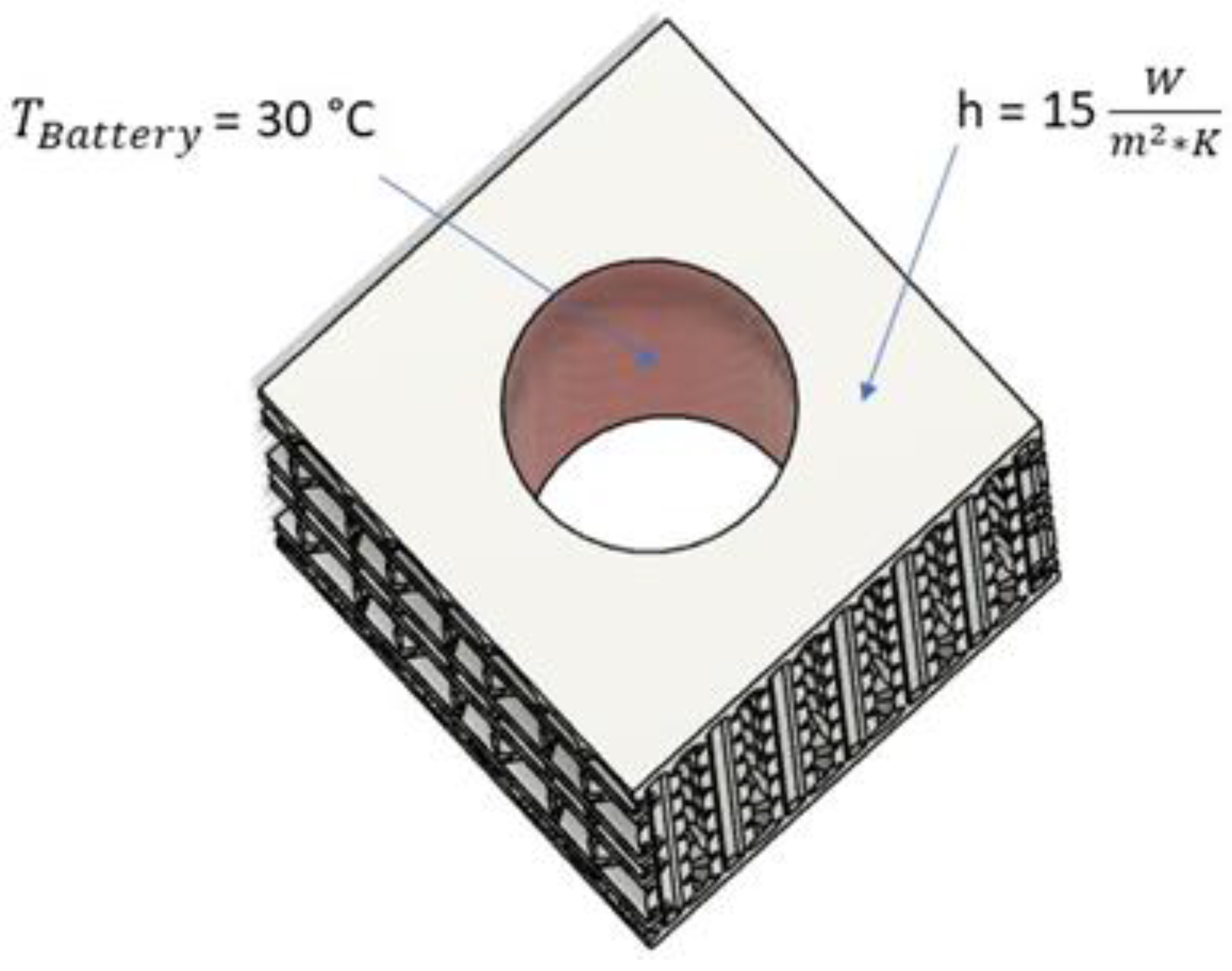
The heat transfer coefficient of the housing was defined as 15 W/m2K as shown in Figure 12.
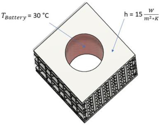
Figure 12.
Heat transfer coefficient housing and battery cell temperature.
With the provided start parameters, you can see the PCM’s influence after only a few seconds. The temperature of the battery is conveyed to the battery pack wall and stored by the PCM. The same is true for the temperature of the cooling lines. The conductive support structure aids heat transfer through the PCM. The temperature distribution in the PCM can be seen in in Figure 13.
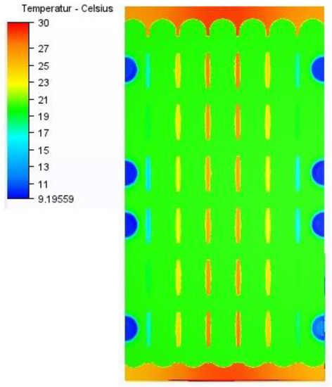
Figure 13.
Temperature distribution PCM.
3. Results
This project investigated the feasibility and effectiveness of passive thermal management of lithium-ion batteries using phase change materials for electric vehicle battery modules. We were able to evaluate different latent heat storage materials and define suitable PCMs for the required temperature range of the selected battery cells. The strong temperature dependency of the performance of lithium-ion batteries can be mitigated by installing a heat storage device with a high energy density such as PCM. Based on the selected batteries of the battery pack and the data of the PCMs, Paraffin RT21 seems to be the most suitable for this application. The highest heat storage capacity of this material is reached at temperatures between 13 °C and 28 °C. It can be assumed that the best temperature range for continuous operation of our batteries should be between 15 °C and 30 °C. This condition is met by using Paraffin RT21.
First, the printable concept with sufficient heat conduction in the material and an integrated heating and cooling concept could be developed. Several iteration loops of design and thermal simulations were required to get the right results.
The component design was created according to the design guidelines for DMLS. As part of this work, we focused exclusively on the design and simulation of the battery pack, so special attention was paid to these aspects. The first simulation of the battery pack shows the temperature distribution in the PCM and the heat transfer from the cooling lines to the support structure. The first simulation of the battery pack shows the temperature distribution in the PCM and the heat transfer from the cooling lines to the support structure. The simulation shows an even heat distribution in the battery pack and shows the advantages of the heat-conducting structure in the PCM. Manufacturing a 3D-printed battery pack is now possible with the developed design. The printing of the structure and its validation in practical experiments will be carried out in future projects.
4. Discussion
The introduction of thermal energy from the outside into the “Battery to PCM” system can result in an even temperature distribution within the battery pack. The strong temperature dependency of the performance of a lithium-ion battery pack can be mitigated by the addition of a heat storage device with a high energy density, such as PCM. Due to the poor heat transfer in PCMs, heat-conducting elements in battery packs are beneficial. Furthermore, additional cooling is necessary for the safe operation of the battery in the event of overheating. These optimizations can be integrated through additive manufacturing options. The use of PCM in a vehicle battery increases the overall weight of the battery, which in turn increases the overall weight of the vehicle and, therefore, energy consumption. To avoid this, the entire system was constantly monitored during the study in order to focus on suitable solutions. In order to accommodate the entire energy of the LIB in the PCM, 0.20 kg of paraffin RT21 per battery cell would be required, as described in Section 2.1.2. Since the battery concept provides for additional external heating or cooling and in order to be able to place the size and weight of the battery pack in a comparable range, we decided to reduce the amount of thermal storage mass to ¼ which corresponds to about 0.05 kg/cell. The advantage of an even temperature distribution in the battery pack is still there. PCMs that meet the requirements are not widely available in the market, which can lead to higher battery pack costs. In this exploratory project, this risk is subordinated to the technical risk, since the economic assessment is doubtful. Battery pack design must include both thermal simulation and consideration of process-dependent design guidelines to ensure optimal thermal behaviour and printability of the complex structure.
Author Contributions
Conceptualization, S.M.T.; methodology, S.M.T., J.Z. and D.Z.; software, J.Z.; validation, R.H.; investigation, S.M.T., J.Z. and D.Z.; resources, S.M.T.; writing—original draft preparation, S.M.T.; writing—review and editing, S.M.T., J.Z. and D.Z.; supervision, R.H. and R.L.; project administration, S.M.T.; funding acquisition, S.M.T. All authors have read and agreed to the published version of the manuscript.
Funding
This research received no external funding.
Data Availability Statement
Not applicable.
Conflicts of Interest
The authors declare no conflict of interest.
References
- Reddy, T.; Linden, D. Linden’s Handbook of Batteries, 4th ed.; McGraw-Hill Companies, Inc.: New York, NY, USA, 2011. [Google Scholar]
- Pesaran, A. Battery Thermal Management in EVs and HEVs: Issue and Solution. In Proceedings of the Advanced Automotive Battery Conference, Las Vegas, NV, USA, 6–8 February 2001. [Google Scholar]
- Nelson, P.; Dees, D.; Amine, K.; Henriksen, G. Modeling thermal management of lithium-ion PNGV batteries. J. Power Sources 2002, 110, 349–356. [Google Scholar] [CrossRef]
- Sterner, M.; Stadler, I. Energiespeicher; Springer: Berlin/Heidelberg, Germany, 2014. [Google Scholar]
- Hauer, A.; Hiebler, S.; Reuß, M. Wärmespeicher; Fraunhofer IRB: Stuttgart, Germany, 2012. [Google Scholar]
- Kenfach, F.; Bauer, M. Innovative Phase Change Material (PCM) for heat storage for industrial applications. In Proceedings of the 8th International Renewable Energy Storage Conference and Exhibition, Berlin, Germany, 8–20 November 2013. [Google Scholar]
- Thaler, S.; Silva, S.F.D.; Hauser, R.; Lackner, R. Experimental Investigation on Phase Change Materials for Thermal Management of Lithium-ion Battery Packs. In Proceedings of the 14th International Renewable Energy Storage Conference 2020 (IRES 2020), Dusseldorf, Germany, 10–12 March 2020; Atlantis Highlights in Engineering. Volume 6. [Google Scholar]
- GmbH, R.T. Rubitherm Technologies GmbH. Available online: https://www.rubitherm.eu/index.php/produktkategorie/organische-pcm-rt (accessed on 23 April 2018).
- Froes, F.H.; Boyer, R. Additive Manufacturing for the Aerospace Industry, 1st ed.; Elsevier: Amsterdam, The Netherlands, 2019; ISBN 9780128140635. [Google Scholar]
- Tromans, G. Developments in Rapid Casting, 1st ed.; John Wiley & Sons: London, UK, 2004; ISBN 9781860583902. [Google Scholar]
- Zhang, J.; Jung, Y.-G. Additive Manufacturing: Materials, Processes, Quantifications and Applications, 1st ed.; Butterworth-Heinemann: Oxford, UK, 2018; ISBN 9780128123270. [Google Scholar]
- Toyserkani, E.; Sarker, D.; Ibhadode, O.O.; Liravi, F.; Russo, P.; Taherkhani, K. Metal Additive Manufacturing, 1st ed.; John Wiley & Sons: Hoboken, NJ, USA, 2021; ISBN 9781119210832. [Google Scholar]
- Niaki, M.K.; Nonino, F. The Management of Additive Manufacturing: Enhancing Business Value, 1st ed.; Springer: Cham, Switzerland, 2017; ISBN 9783319563091. [Google Scholar]
- Kadkhodapour, J.; Dchmauder, S.; Sajadi, F. Direct Metal Laser Sintering—Setup-dependent material characteristics of topologies for multi-functional part optimization. In Quality Analysis of Additively Manufactured Metals, 1st ed.; Elsevier: Amsterdam, The Netherlands, 2023; ISBN 978-0-323-88664-2. [Google Scholar]
- Deutschland, W. Positionspapier: Bedeutung und Weiterentwicklung von Simulation in der Wissenschaft. 2014. Available online: https://www.wissenschaftsrat.de/download/archiv/4032-14.pdf (accessed on 6 September 2018).
- ANSYS, Inc. Ansys Fluent Tutorial Guide; ANSYS, Inc.: Canonsburg, PA, USA, 2011. [Google Scholar]


Disclaimer/Publisher’s Note: The statements, opinions and data contained in all publications are solely those of the individual author(s) and contributor(s) and not of MDPI and/or the editor(s). MDPI and/or the editor(s) disclaim responsibility for any injury to people or property resulting from any ideas, methods, instructions or products referred to in the content. |
© 2023 by the authors. Licensee MDPI, Basel, Switzerland. This article is an open access article distributed under the terms and conditions of the Creative Commons Attribution (CC BY) license (https://creativecommons.org/licenses/by/4.0/).