1. Introduction
UHPC, ultra-high-performance concrete, is a remarkable engineering material with ultra-high strength, ultra-low water absorption, super durability, and corrosion resistance. Its compressive strength can reach over 120 MPa, which is three to six times the compressive strength of ordinary concrete [
1]. Its mechanical properties are close to those of steel structures, and it has excellent explosion, corrosion, and wear resistance. The UHPC layer forms a steel–UHPC composite structure with steel bridge decks through shear nails and a steel mesh, which forces the concrete and steel girders together, improves the lateral stiffness of the bridge deck, significantly reduces the local stress concentration caused by wheel loads, and alleviates the fatigue cracking problem of orthotropic bridge decks [
2,
3,
4,
5]. At the same time, the high-strength and high-durability performance of UHPC can reduce disease caused by bridge deck concrete in the later service stage [
6,
7].
Due to the large span and expansiveness of the bridge deck, the on-site pouring scale of UHPC is enormous when using this ultra-high-performance concrete composite bridge deck in cable-stayed bridges. Due to the limitations of construction equipment, it is necessary to carry outpouring in sections and blocks separately. However, unlike previous asphalt concrete bridge deck pouring, the UHPC layer gradually forms a composite bridge deck with the steel box girder after pouring, gradually increasing the stiffness of the bridge deck system and participating in the stress on the bridge deck. This effect constantly changes the stress state of the bridge structure during the UHPC casting process, meaning that the internal force of the structure undergoes multiple redistributions during the construction process; this redistribution of internal forces will ultimately affect the implementation of the designed bridge state (cable force, bridge linearity, bridge deck and steel box girder stress) [
8,
9,
10].
There needs to be more research on the effects of the segmented casting of the UHPC layer on the stress and linear shape of large-span bridges.
Jiang Yuyan [
8,
9] studied the influence of the pouring scheme on a finished suspension bridge when a UHPC deck was used. The research shows that the pouring sequence, the setting of a post-pouring section and deck counterweight significantly influenced the finished line shape and internal force of the suspension bridge. Using the no counterweight scheme or local counterweight pouring scheme is recommended. Due to the differences in construction methods and structural stress, the above research conclusions for suspension bridges do not apply to cable-stayed bridges.
Peng Qiao [
10] studied the influence of the construction organization of the main beam roof pavement of a suspension bridge on the stress of the main beam and pavement and analyzed the influence of the structural parameters of steel box girders and asphalt concrete materials on the stress of the pavement. This study focuses on asphalt concrete pavement layers, and the research conclusion does not apply to UHPC pavement layers that participate in bridge deck structural stress.
Other scholars have conducted many studies on the construction processes of cable-stayed bridges, such as cable tensioning and main beam erection, but have not addressed the impact of bridge deck pavement methods (especially of using UHPC involved in bridge deck stress) on the completion of cable-stayed bridges.
Therefore, it is necessary to study the reasonable pouring scheme of the UHPC layer on the bridge deck of large-span cable-stayed bridges and conduct a multi-dimensional comparison and selection from the structural safety of the construction state to the advantages and disadvantages of the completed bridge state (internal force, and linear shape).
2. Engineering Background and Calculation Model Establishment
2.1. Project Overview
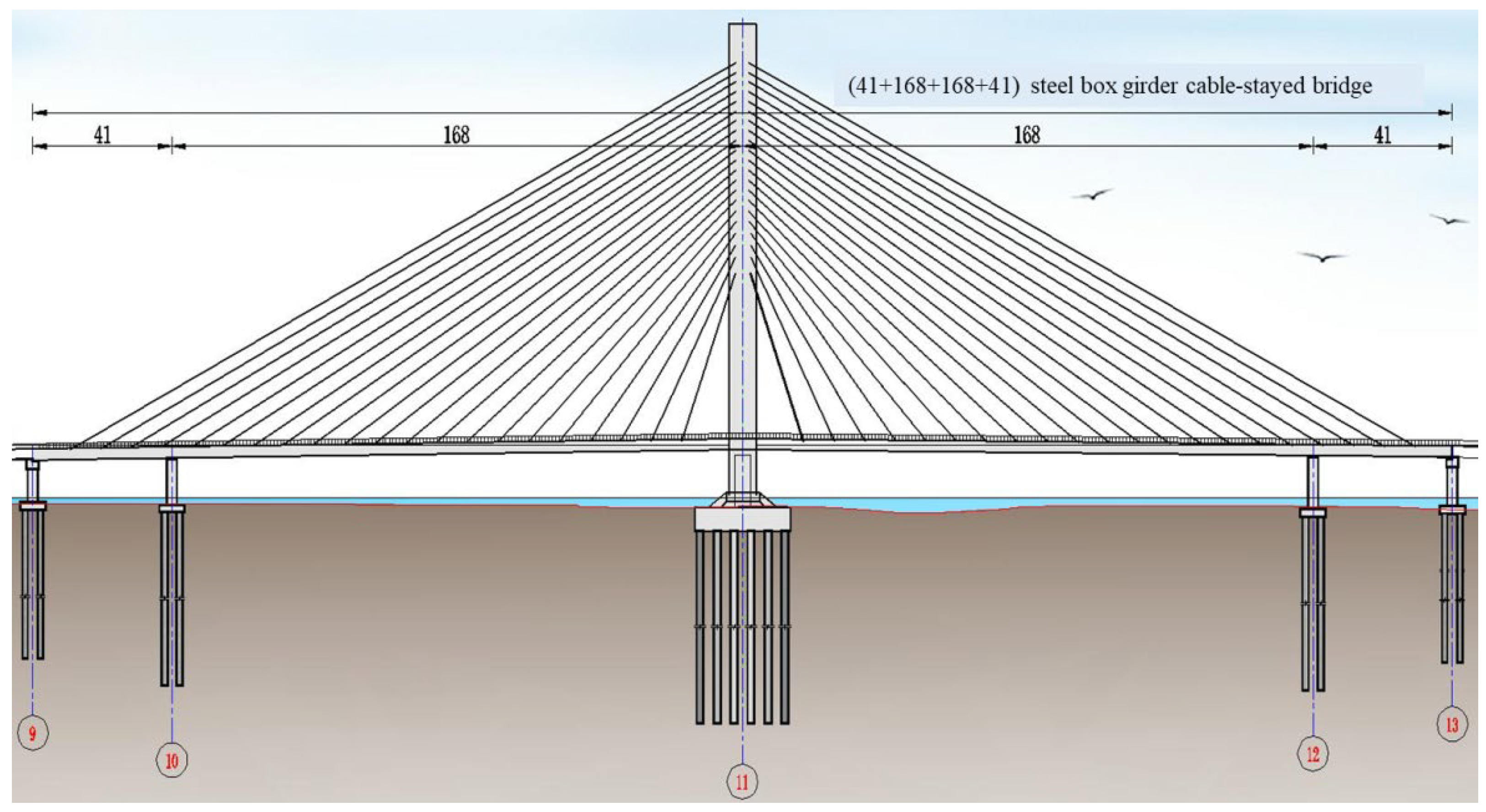
The main bridge of a certain project adopts a single tower and double-span cable-stayed bridge as shown in
Figure 1. The central tower is an arc-shaped concrete tower, and the main beam is a steel UHPC composite steel box beam as shown in
Figure 2. The cables are parallel steel cables with spatial double-cable surfaces and a fan-shaped layout. In order to improve the structural stiffness of the cable-stayed bridge and effectively reduce the deflection of the main beam and the horizontal displacement of the tower’s top under a live load, an auxiliary pier is set at a distance of 41 m from the transition pier for both main spans, so that the span arrangement of the main bridge is 41 + 168 + 168 + 41 = 418 m.
The main beam adopts a lightweight composite structure, consisting of a streamlined flat steel box beam and UHPC, ultra-high-performance concrete, panel. These two are connected by shear nails as shown in
Figure 3, with a standard section beam height of 3 m (referring to the road’s centerline). Cast iron block weights are installed at the auxiliary and transition piers. The cable tower is a double-column variable cross-section curved concrete tower with a total height of 125 m and a height of 106.628 m above the bridge deck. The columns and beams on the tower use hollow thin-walled sections; two rectangular section piers are installed on the bearing platform at the cable tower to support the main beam. The anchorage zone on the cable-stayed beam is located on the outer side of the sidewalk, with a spacing of 9 m along the bridge direction.
The cross-section of the main bridge is shown in
Figure 2. Other bridge design information is shown in
Table 1.
2.2. Original Construction Details
Based on this bridge system’s characteristics and the project’s site conditions, the designer suggests constructing the main bridge using the full hall support method. The primary construction process is as follows and shown in
Figure 4:
(1) Leveling the site, setting out the construction line, determining the pile position and constructing an access road within the main bridge while the factory begins processing steel beams; (2) constructing a bored pile and pouring the bearing platform of it; (3) constructing pier columns and connecting pier cap beams; (4) constructing cable towers and installing full hall supports; (5) assembling the steel box girder section of the main beam on the support platform; (6) welding the bridge deck reinforcement and shear nails, pouring the UHPC (ultra-high-performance concrete) pavement layer on the bridge deck; (7) tensioning stay cables; (8) dismantling the full hall bracket; (9) constructing the sidewalk, railing, expansion joint, drain hole and bridge deck pavement; calculating whether or not secondary tensioning is required based on the measured cable force; (10) completing the construction of the entire bridge.
According to the above construction organization plan, the UHPC bridge deck layer is first completed during the full support stage of the main beam. Then, cable tension is applied. Hence, under the full support construction plan, the pouring sequence of the UHPC layer on the bridge deck will not affect the final internal cable force.
2.3. Adjustment of Construction Plan
Considering that the flood season is approaching on site, the full support pouring plan has a significant impact on the flood discharge of the river channel, and it is not possible to remove the full support according to the original plan after pouring the UHPC layer of the bridge deck and tensioning the diagonal cables.
The UHPC layer uses a segmented pouring method and adopts a flow process. According to the project scale and personnel organization arrangement, the UHPC layer of the entire bridge is divided into eight sections for pouring. This article proposes three major construction plans based on whether or not to balance the weight and the degree of balance, namely (1) unbalanced pouring plan I; (2) pre-weight UHPC layer weight Scheme II; (3) pre-balanced UHPC layer and bridge deck phase II dead load plan III.
2.4. Calculation and Analysis Model
This bridge is analyzed using the bridge finite element analysis software Midas Civil V2019. The overall model of the cable-stayed bridge adopts a fishbone model, with beam elements used for the pier columns, and bridge towers, main beams. Truss elements used for the stay cables as shown in
Figure 5. In the calculation, construction processes such as foundation construction, bridge tower construction, main beam erection, lower cable tensioning, and bridge deck slabbing are considered. The main beam section adopts a steel–concrete construction stage joint section, and the UHPC part of the joint section is activated one by one according to the construction sequence to participate in the structural internal stress.
The unit weight of steel is taken as 78.5 kN/m3; the gravity density of UHPC is taken as 28.0 kN/m3. C55 concrete is taken as 26.0 kN/m3. The second-phase dead load is taken at approximately 73.0 kN/m.
The UHPC detailed parameters are shown in
Table 2.
The initial tension cable force is shown in
Table 3.
In terms of the content of the comparative analysis of pouring plans, the procedure was is as follows: (1) during the construction phase, the primary consideration is the impact of the post-pouring concrete (UHPC) on the already poured concrete (UHPC), including additional deformation and tensile stress of the formed UHPC bridge decks; (2) during the completion stage, the primary considerations include the bridge shape, cable force uniformity, UHPC bridge deck tensile stress, and steel box girder stress. The benchmark model for comparative analysis is the original design pouring plan (full support pouring plan).
3. Comparison and Impact Analysis of Pouring Schemes for UHPC Layer on Bridge Deck
3.1. Analysis of the Impact of Unbalanced Weight Pouring Scheme I and Bridge Deck Pouring Sequence
Based on the combination of single and double pouring, interval or continuous pouring, eight possible sub-construction schemes are proposed, as shown in
Table 4.
The calculation results of the above eight sub-schemes show that the cable force, bridge line shape, and steel box girder stress of the completed bridge are close to the original design scheme values without significant differences. The specific details are as follows: the error of the cable force for each sub-scheme of the completed bridge is between ±1% and ±2%; the linear error of the completed bridge is within ±5 mm; the stress difference of the completed steel box girder is between 6.8 and 7.2 MPa. Due to the large amount of data, they will not be presented in this article.
The significant differences from the original design plan are the additional deformation and stress during the construction stage, as well as the tensile stress of the bridge deck during the completion stage, as shown in
Table 5,
Table 6 and
Table 7. The longitudinal position along the bridge’s mileage in the table takes the bridge tower as the longitudinal coordinate point, 0, with positive values indicating the direction along bridge.
According to the calculation results of Scheme I without counterweight pouring, the following conclusions are drawn:
(1) During the construction phase, the areas with high tensile stress in the UHPC bridge deck of each sub-scheme are located near the auxiliary pier, with stress values ranging from 1.8 to 3.7 MPa, which are slightly higher than the original design value; the additional deformation of the bridge deck caused by each sub-plan during the construction phase is about −24 mm, which is significantly different from the original design plan.
(2) During the completion stage of the bridge, the tensile stress of the UHPC bridge deck in each sub-scheme is 13–14 MPa, which is significantly higher than the original design scheme’s 6.2 MPa. Compared to the construction stage, the stress increases by about 11 MPa, with the higher stress located near the auxiliary pier; although UHPC has strong crack resistance (usually with a tensile strength of 10–25 MPa), the large tensile stress of the completed bridge is unfavorable for the later bearing capacity of the bridge.
(3) The deformations and structural stresses of sub-schemes 1 to 8 during the construction and bridge completion stages are relatively similar, indicating that the pouring sequence of blocks and frames has no significant impact on the pouring of UHPC concrete. The obvious influencing factor is the overall pouring direction, which is ① when pouring from the edge to the tower end first (sub-schemes 1 to 6), or ② pouring from the tower end to the edge first (sub-schemes 7 to 8). Overall, pouring from the tower end to the edge first is beneficial for reducing the tensile stress values of UHPC bridge decks during the construction and completion stages, but the improvement is not significant.
3.2. Analysis of the Impact of Setting up a Post-Pouring Strip in Scheme I without Counterweight Pouring
According to the analysis in
Section 3.1, the tensile stress of the UHPC bridge deck near the auxiliary pier is relatively high, mainly caused by the negative bending moment. It is considered to set up post-cast sections within a range of about 20 m near the bridge tower and auxiliary piers to reduce the considerable tensile stress of the UHPC bridge deck. According to the overall construction organization, the post-pouring section is poured before the dead load of the second phase of bridge deck construction. The schematic diagram of the scheme is shown in
Figure 6.
According to the calculation results of the above scheme, after setting the post-pouring strip, the tensile stress of the UHPC bridge deck during the completion stage decreases by about 2 MPa, and the additional stress during the construction stage decreases by about 0.3 MPa. Other indicators are not significantly different from those without the post-pouring strip.
The main reason for the small effect of setting up a post-pouring strip is that a post-pouring section can only solve the first-stage stress during the UHPC pouring period and cannot solve the second-stage stress caused by the large second-stage dead load (73 kN/m, about twice the weight of the UHPC bridge deck) after UHPC pouring is performed.
3.3. Bridge Deck Counterweight Plan
In order to reduce the tensile stress of the UHPC bridge deck at the support points (near the auxiliary piers and bridge towers) in the above plan, plan I, without counterweights, a sandbag pre-counterweight plan is used before pouring UHPC on the bridge deck. According to the different weights of the counterweights, “UHPC weight balancing scheme II” and “UHPC layer and bridge deck dead load balancing scheme III” are considered. Each scheme is further divided into two sub-schemes based on the scope of counterweights: local counterweights and full-bridge counterweights. The entire bridge counterweight using the corresponding scheme within the 418 m range of the entire bridge deck.
In the local counterweight scheme, without a loss of generality, is used within 20 m of the middle span of the auxiliary pier and 84 m of the middle span of the main span. According to the relevant content in
Section 3.1 of this article, there is little difference between single-, double -width, interval or continuous pouring combination schemes. Therefore, the above effects are no longer considered in the pre-weight scheme, and the local weight scheme is shown in
Figure 7.
The calculation results of the above four sub-schemes show that compared those in the original design scheme as shown in
Figure 8, the cable force error of each sub-scheme is between ±0.5% and ±1.5%; the linear error of the completed bridge is within ±4 mm; the stress difference of the completed steel box girder is between 5.4 and 7.0 MPa, which is close to the original design value and has no significant difference. Due to the large amount of data, it will not be presented in this article.
The significant difference from the original design scheme is the additional deformation and stress during the construction stage, as well as the tensile stress of the bridge deck during the completion stage, as shown in
Table 8,
Table 9 and
Table 10. The longitudinal position along the bridge mileage in the table takes the bridge tower as the longitudinal coordinate point, 0, with positive values indicating the direction of mileage increase and negative values indicating the direction of mileage decrease.
Based on the calculation results of UHPC weight balance Scheme II, UHPC layer, and Phase II dead load balance Scheme III, the following conclusions are drawn:
(1) During the construction phase, when using full-weight bridge counterweights, the tensile stress and additional deformation of the UHPC bridge deck are relatively small, which is consistent with the full support pouring plan; when using the local counterweight scheme, the tensile stress of the bridge deck slightly increases to 1.4 MPa, and the additional deformation of the bridge deck is −7.684 mm.
(2) During the bridge completion stage, the maximum tensile stress of the UHPC bridge deck of each sub-scheme is 1.0~12.7 MPa, located near the bridge tower or auxiliary pier position; when using the full-bridge-weight UHPC layer and second-phase dead load Scheme III of the bridge deck, the tensile stress of the completed UHPC bridge deck is reduced to 1.0 MPa; the tensile stress of the UHPC bridge deck of the completed bridge gradually increases with the reduction in the counterweight range and weight.
In Jiang Yuqin’s research [
8,
9] on the UHPC deck pavement of a suspension bridge, optimizing the UHPC pouring sequence and setting the post-pouring section had specific effects on improving the state of the completed bridge, and it more obviously improved the UHPC stress of the bridge deck. The conclusions are different from the conclusions of this study. The main reason is that the suspension bridge mentioned in Jiang Yuchao’s paper is a single-suspension span without the adverse effect of auxiliary piers. In contrast, the cable-stayed bridge in this paper has the effect of auxiliary piers. The reaction force of auxiliary piers will cause a negative bending moment in the main beam, resulting in sizeable tensile stress on the UHPC bridge deck.
However, in terms of the influence of counterweight measures on the completed bridge state and UHPC stress, the research results in this paper are more consistent with the research conclusions of Jiang Yuqin on the UHPC deck pavement of the suspension bridge.
4. Comparative Analysis and Conclusions
According to the above analysis in this article, from the impact of additional deformation during the construction phase, the additional tensile stress of the UHPC bridge deck, the bridge shape, the uniformity of cable force, the stress of the UHPC bridge deck and the stress of steel box girder during the bridge stage, the main conclusions are as follows:
(1) Compared to the full hall support scheme, regardless of whether or not counterweight measures are used, the bridge line shape, cable force, and steel box girder stress during the completion stage of each scheme are not significantly different; the cable force error of the completed bridge is between ±1% and ±2%; the linear error of the completed bridge is within ±5 mm; the stress difference of the completed steel box girder is between 6.8 and 7.2 MPa. When using bridge deck counterweight measures, all indicators will be slightly better than they will without counterweight measures.
(2) When the UHPC bridge deck is poured without a counterweight (Scheme I), significant additional deformation (−24.8–12.5 mm) and additional stress (0.8–3.7 MPa) will occur during the construction phase; after the completion of the bridge, this plan will have a limited impact on the bridge shape and cable stress of the cable-stayed bridge, but it will generate significant tensile stress (about 14 MPa) in the UHPC layer. For this construction plan, adjusting the pouring sequence of the UHPC bridge deck will have a limited impact in terms of improving the aforementioned adverse effects. Setting post-pouring strips near auxiliary piers and bridge towers can reduce the stress of the UHPC bridge deck after completion by about 2 MPa.
(3) When the UHPC weight balance pouring method is used for UHPC bridge deck (Scheme II), there will be certain additional deformation (−7.7~1.7 mm) and additional stress (0.8~1.4 MPa) during the construction stage; after the bridge is completed, significant tensile stress (11.9–12.7 MPa) will be generated in the UHPC layer. When balancing the weight of the entire bridge deck area, all indicators will be better than the weight of local areas on the bridge deck.
(4) When the UHPC layer on the bridge deck and second-phase constant load counterweight Scheme III are used, the improvement of various indicators during the construction phase will be the same as that observed in Scheme II. The improvement of the UHPC layer during the completion phase will be significant, and can be significantly reduced to 1.0 MPa during the implementation of a full bridge counterweight. Besides, it can also be reduced to 8.2 MPa during the implementation of a local counterweight.
In summary, when using the UHPC bridge deck structure for cable-stayed bridges, it is recommended to use a counterweight pouring scheme for UHPC pouring on the bridge deck, when the construction site conditions are limited; at least, local weight balancing schemes should be adopted, combined with comprehensive technical measures such as setting up post-pouring strips at the auxiliary piers and bridge towers.
Author Contributions
Conceptualization, J.S.; methodology, J.S.; software, J.S.; validation, J.S. and Z.C.; formal analysis, J.S.; investigation, J.S. and Z.C.; resources, J.S. and Z.C.; data curation, J.S. and Z.C.; writing—original draft preparation, J.S.; writing—review and editing, J.S.; visualization, J.S.; supervision, J.S.; project administration, J.S.; funding acquisition, J.S. and Z.C. All authors have read and agreed to the published version of the manuscript.
Funding
This research received no external funding.
Institutional Review Board Statement
Not applicable.
Informed Consent Statement
Not applicable.
Data Availability Statement
The data presented in this study are available on request from the corresponding author.
Conflicts of Interest
The authors declare no conflict of interest.
References
- Plateau; Gao, Q.; Zhang, F.; Wang, J. Research and Application of Ultra High Performance Concrete Steel Bridge Deck Pavement in Desert Regions. Highway 2020, 65, 140–144. [Google Scholar]
- Wang, L. Student on the Steel Ultra Thin UHPC Composite Bridge Deck Based on Ultra Short Study; Huanan University: Changsha, China, 2020. [Google Scholar]
- Zhou, L.; Zhang, G.; Wang, M. Study of implementation effect of Steel-UHPC Composite Bridge Deck on Junshan Changjiang River. Bridge Constr. 2020, 50, 49–54. [Google Scholar]
- Zou, D. Application Research of UHPC Pavement in Improving Bearing Capacity of Existing Concrete Beam Bridge Kunming; University of Science and Technology: Hefei, China, 2020. [Google Scholar]
- Peng, X.; Wang, M. Application of UHPC to Steel Deck Pavement of Long Span Railway Bridge. World Bridges 2020, 48, 77–81. [Google Scholar]
- Xu, Y.; Zhang, H.; Cui, L. Research on the application of ultra-high performance concrete steel deck pavement on suspension steel box girder bridge deck. Highw. Traffic Sci. Technol. 2020, 16, 171–175. [Google Scholar]
- Liao, W.; Chen, L.; Gao, L.; Wang, M. Using UHPC to Renovate Deck of Junshan Changjiang River Bridge in Wuhan and Effect Analysis. World Bridges 2019, 47, 65–69. [Google Scholar]
- Shen, R.; Jiang, Y.; Zhang, J. Study on lnfluence of Construction Schemes of Cast in Place STC Payment System on Completion State of Suspension Bridge. J. China Foreign Highw. 2019, 39, 73–77. [Google Scholar]
- Jiang, Y. Study on the Influence of the Construction Schemes of Cast in Place STC Bridge Deck Payment on the Finished Dead State of Suspension Bridge; Southwest Jiaotong University: Chengdu, China, 2018. [Google Scholar]
- Peng, Q. Mechanical Influence of Pavementabout Suspension Bridge Deck Pavement Construction Sequence and Steel Box Girder Structure; Chongqing Jiaotong University: Chongqing, China, 2016. [Google Scholar]
Figure 1.
Bridge type layout, the number of each pier is shown below. (Unit: m).
Figure 1.
Bridge type layout, the number of each pier is shown below. (Unit: m).
Figure 2.
Cross-section of main beam (Unit: cm).
Figure 2.
Cross-section of main beam (Unit: cm).
Figure 3.
UHPC bridge deck structure diagram (Unit: mm).
Figure 3.
UHPC bridge deck structure diagram (Unit: mm).
Figure 4.
Original design and construction process.
Figure 4.
Original design and construction process.
Figure 5.
Overall calculation and analysis model.
Figure 5.
Overall calculation and analysis model.
Figure 6.
Schematic diagram of setting up a post-pouring strip for Scheme I without counterweight pouring, numbers refer to sequence of pouring.
Figure 6.
Schematic diagram of setting up a post-pouring strip for Scheme I without counterweight pouring, numbers refer to sequence of pouring.
Figure 7.
Schematic diagram of Scheme II (Scheme III)—local weighting sub-scheme, numbers refer to sequence of pouring.
Figure 7.
Schematic diagram of Scheme II (Scheme III)—local weighting sub-scheme, numbers refer to sequence of pouring.
Figure 8.
Linear comparison of completed bridges between Scheme II and Scheme III.
Figure 8.
Linear comparison of completed bridges between Scheme II and Scheme III.
Table 1.
The bridge design information.
Table 1.
The bridge design information.
| Term | Detail |
|---|
| Design period | 100 years |
| Vehicle load level | Highway—Class I; |
| Bridge structure | Single tower double cable plane
cable-stayed bridge |
| Structural system | Semi-floating system, with elastic limit devices and dampers installed vertically and elastic–plastic limit devices installed horizontally |
| Type of stay cable | Parallel steel wire cable, 1670 MPa, PES7-109.PES7-121, PES7-139
PES7-151; spacing: 9 m (along the bridge), 2.5 m (vertical) |
| Steel box girder | Q345qD; Width 36.5 m, height 3 m |
| Bridge deck pavement | 5 cm UHPC, Φ 10 bi-directionally reinforced with a spacing of 37.5 mm |
| Phase II dead load | Asphalt concrete pavement + sidewalk slab + sidewalk guardrail + central median strip guardrail + wind nozzle |
| Cable tower | Double column variable cross-section curved concrete tower; 125 m height; C55 |
| Foundation | Group pile foundation; C35 |
| Original construction methods | Main beam, bridge deck, and phase II dead load are all under full hall support. |
Table 2.
UHPC parameters.
Table 2.
UHPC parameters.
Elastic Modulus
| Poisson’s Ratio
| Uniaxial Tensile Strength
| Uniaxial Compressive Strength
|
|---|
| 37,600 | 0.2 | 22 | 77.4 |
Table 3.
Specification and force of stay cables.
Table 3.
Specification and force of stay cables.
Cable
No. | Cable Type | Initial Tension Force (kN) | Position (m) |
|---|
| AVG |
|---|
| S21 | PES(C)7-151 | 2987.5 | 198 |
| S20 | PES(C)7-151 | 2851.3 | 189 |
| S19 | PES(C)7-139 | 2504.4 | 180 |
| S18 | PES(C)7-121 | 2289.7 | 171 |
| S17 | PES(C)7-121 | 2225.7 | 162 |
| S16 | PES(C)7-121 | 2196.4 | 153 |
| S15 | PES(C)7-139 | 2551.7 | 144 |
| S14 | PES(C)7-139 | 2526.3 | 135 |
| S13 | PES(C)7-151 | 2578.6 | 126 |
| S12 | PES(C)7-151 | 2647.5 | 117 |
| S11 | PES(C)7-151 | 2460.1 | 108 |
| S10 | PES(C)7-139 | 2311.1 | 99 |
| S9 | PES(C)7-139 | 2242.7 | 90 |
| S8 | PES(C)7-139 | 2273.1 | 81 |
| S7 | PES(C)7-139 | 2159.7 | 72 |
| S6 | PES(C)7-139 | 2068.1 | 63 |
| S5 | PES(C)7-121 | 1936.3 | 54 |
| S4 | PES(C)7-121 | 1949.3 | 45 |
| S3 | PES(C)7-109 | 1792.7 | 36 |
| S2 | PES(C)7-109 | 1733.2 | 27 |
| S1 | PES(C)7-109 | 1710.0 | 18 |
Table 4.
Calculation results of lateral force on box girders under single-factor action (unit: MPa).
Table 5.
Additional deformation of poured UHPC segments during the construction phase of Scheme I without counterweight pouring.
Table 5.
Additional deformation of poured UHPC segments during the construction phase of Scheme I without counterweight pouring.
| Scheme Type | No. | Sub-Scheme Name | Downward Deformation
(mm) | Position
(m) | Location Description | Upward Deformation
(mm) | Position
(m) | Location Description |
|---|
| Original design | 0 | Full hall support | 0 | —— | —— | 0 | —— | —— |
Unbalanced pouring
Scheme I | 1 | Single interval | −24.487 | −81 | Small mileage mid span | 9.347 | 126 | Large mileage mid span |
| 2 | Double spacing | −24.799 | −81 | 9.374 | 126 |
| 3 | Single-amplitude symmetry | −24.742 | −81 | 9.374 | 126 |
| 4 | Double-amplitude symmetry | −24.614 | −81 | 9.374 | 126 |
| 5 | Single progressive | −24.787 | −81 | 9.374 | 126 |
| 6 | Double-amplitude progressive | −24.722 | −81 | 9.374 | 126 |
| 7 | Single-frame first tower end then edge end | −24.824 | −81 | 12.488 | 117 |
| 8 | Double-width first tower end then edge end | −24.785 | −81 | 12.488 | 117 |
Table 6.
Additional stresses on poured UHPC segments during the construction phase of Scheme I without counterweight pouring.
Table 6.
Additional stresses on poured UHPC segments during the construction phase of Scheme I without counterweight pouring.
| Scheme Type | No. | Sub-Scheme Name | Maximum Tensile Stress (MPa) | Position (m) | Location Description |
|---|
| Original design | 0 | Full hall support | 0.8 | −7.5 | Near the bridge tower |
Unbalanced pouring
Scheme I | 1 | Single interval | 2.2 | −169 | Near the auxiliary pier |
| 2 | Double spacing | 2.7 | −169 | Near the auxiliary pier |
| 3 | Single-amplitude symmetry | 2.7 | −168 | Near the auxiliary pier |
| 4 | Double-amplitude symmetry | 3.2 | −171 | Near the auxiliary pier |
| 5 | Single progressive | 2.9 | −169 | Near the auxiliary pier |
| 6 | Double-amplitude progressive | 3.7 | −169 | Near the auxiliary pier |
| 7 | Single-frame first tower end then edge end | 1.8 | −6 | Near the bridge tower |
| 8 | Double-width first tower end then edge end | 1.8 | −168 | Near the auxiliary pier |
Table 7.
Unbalanced pouring Scheme I—UHPC bridge deck tensile stress during the completion stage.
Table 7.
Unbalanced pouring Scheme I—UHPC bridge deck tensile stress during the completion stage.
| Scheme Type | No. | Sub Scheme Name | Maximum Stress Value (MPa) | Longitudinal Bridge Position (m) | Location Description |
|---|
| Original design | 0 | Full hall support | 6.2 | −169 | Near the auxiliary pier |
Unbalanced pouring
Scheme I | 1 | Single interval | 13.5 | −168 | Near the auxiliary pier |
| 2 | Double spacing | 13.5 | −168 | Near the auxiliary pier |
| 3 | Single-amplitude symmetry | 13.7 | −168 | Near the auxiliary pier |
| 4 | Double-amplitude symmetry | 14 | −168 | Near the auxiliary pier |
| 5 | Single progressive | 13.5 | −168 | Near the auxiliary pier |
| 6 | Double-amplitude progressive | 13.5 | −168 | Near the auxiliary pier |
| 7 | Single-frame first tower end then edge end | 13 | −168 | Near the auxiliary pier |
| 8 | Double-width first tower end then edge end | 13.2 | −168 | Near the auxiliary pier |
Table 8.
Additional deformation of poured UHPC segments during the construction phase of the counterweight pouring plan.
Table 8.
Additional deformation of poured UHPC segments during the construction phase of the counterweight pouring plan.
| Scheme Type | No. | Sub-Scheme Name | Downward
Deformation
(mm) | Position
(m) | Location Description | Up Deformation (mm) | Position
(m) | Location Description |
|---|
| Original design | 0 | Full hall support | 0 | —— | —— | 0 | —— | —— |
UHPC Weight Counterweight
Scheme II | 9 | Partial-weight UHPC weight | −7.684 | −126 | Small mileage mid span | 1.788 | 54 | Large mileage mid span |
| 10 | Full-weight UHPC weight | −0.005 | −81 | 0.005 | 126 |
| UHPC Layer and Bridge Deck Dead Load Balancing Scheme III | 11 | Partial-counterweight, full deck weight | −7.684 | −126 | 1.788 | 54 |
| 12 | Full-counterweight, full deck weight | −0.005 | −105 | 0.005 | 102 |
Table 9.
Additional stresses on poured UHPC segments during the construction phase of the counterweight pouring plan.
Table 9.
Additional stresses on poured UHPC segments during the construction phase of the counterweight pouring plan.
| Scheme Type | No. | Sub Scheme Name | Maximum Tensile Stress (MPa) | Position
(m) | Location Description |
|---|
| Original design | 0 | Full hall support | 0.8 | —— | Full bridge range |
| UHPC Weight Balancing Scheme II | 9 | Partial-weight UHPC weight | 1.4 | −6 | Near the bridge tower |
| 10 | Full-weight UHPC weight | 0.8 | —— | Full bridge range |
| UHPC Layer and Bridge Deck Dead Load Balancing Scheme III | 11 | Partial-counterweight, full deck weight | 1.4 | −6 | Near the bridge tower |
| 12 | Full-counterweight, full deck weight | 0.8 | —— | Full bridge range |
Table 10.
Tensile stress of UHPC bridge deck during the completion stage of the counter weight pouring plan.
Table 10.
Tensile stress of UHPC bridge deck during the completion stage of the counter weight pouring plan.
| Scheme Type | No. | Sub Scheme Name | Maximum Tensile Stress (MPa) | Position
(m) | Location Description |
|---|
| Original design | 0 | Full hall support | 6.2 | −169 | Near the auxiliary pier |
| UHPC Weight Balancing Scheme II | 9 | Partial weight UHPC weight | 12.7 | −168 | Near the auxiliary pier |
| 10 | Full weight UHPC weight | 11.9 | −168 | Near the auxiliary pier |
| UHPC Layer and Bridge Deck Dead Load Balancing Scheme III | 11 | Partial counterweight, full deck weight | 8.2 | −168 | Near the auxiliary pier |
| 12 | Full counterweight, full deck weight | 1 | −1 | Near the bridge tower |
| Disclaimer/Publisher’s Note: The statements, opinions and data contained in all publications are solely those of the individual author(s) and contributor(s) and not of MDPI and/or the editor(s). MDPI and/or the editor(s) disclaim responsibility for any injury to people or property resulting from any ideas, methods, instructions or products referred to in the content. |
© 2023 by the authors. Licensee MDPI, Basel, Switzerland. This article is an open access article distributed under the terms and conditions of the Creative Commons Attribution (CC BY) license (https://creativecommons.org/licenses/by/4.0/).


