1. Introduction
A quite common architectural layout for large single-storey RC frames, typically housing industrial plants, warehouses, gyms, and logistics centers, provides the presence of “drift-sensitive” masonry infills and glazed curtain walls. The last usually form an upper band providing natural light to the interior spaces (see
Figure 1). The Italian building stock contains plenty of these buildings, most of them raised more than forty years ago based on outdated technical standards and often designed to withstand gravitational loads only. The seismic retrofitting of these building entails challenges due to the usual poor detailing (and/or inadequacy) of RC elements’ cross-sections and the vulnerability of both masonry infills and windows to lateral drifts.
In addition to more conventional interventions (e.g., through shear walls), substandard RC structures can be retrofitted through a relatively low number of dissipative braces deployed in specific locations of the frame. With respect to technologically more sophisticated viscous dampers, steel hysteretic dampers (SHD) provide supplemental energy dissipation and stiffening with greater affordability and less onerous maintenance.
The response of SHDs is not (or only slightly) affected by velocity; indeed, their force–displacement characteristic is conventionally expressed by means of bilinear hysteretic models. These devices are usually inserted along diagonal braces to undergo large plastic deformation within sacrificial mild steel components during severe earthquakes. This allows most of the earthquake-induced energy to be absorbed, reducing the damages to the main frame.
The first SHDs were introduced in the 1970s [
1]. Subsequently, SHDs exploiting plastic deformations induced by axial loads [
2], shear loads [
3], bending [
4,
5], and torsion [
6] have been developed. In recent years, the number of worldwide applications for the seismic retrofit of public buildings such as schools [
7,
8,
9] and hospitals [
10] has been rapidly increasing. Frontier studies have focused on the assessment of the actual cyclic engagement (i.e., low cycle fatigue) of the dampers [
11] and on their suitability for the protection of acceleration-sensitive non-structural components during minor seismic events [
12]. Indeed, according to the most common design practice [
13,
14], SHDs are designed to exceed the plastic threshold only under severe ultimate limit state earthquakes. Otherwise, during weak serviceability events, they offer a negligible energy dissipation (i.e., damping) and a high stiffening effect, as they are engaged in their elastic range. In certain cases, this stiffening effect can have unfavourable results, i.e., higher storey accelerations; however, this drawback can be effectively addressed through the employment of dampers featuring adaptive (i.e., multi-step) yielding thresholds that are progressively activated based on the intensity of the earthquake [
15].
With respect to the protection level of the main frame, design procedures for braced frames can be grouped into two categories: (1) methods that aim to keep the main structure within its elastic range; and (2) methods that envisage controlled plastic excursions.
Within the first category, Filiatrault and Cherry (1988) [
16] proposed a procedure based on minimizing the discrepancy between the input seismic energy and the energy dissipated by the hysteretic braces (“Vibrating Energy Surface”). In later refinements [
17], the same authors introduced a “Relative Performance Index” relating the energy dissipated within the braces and that stored in the indefinitely-elastic bare frame.
A larger number of design procedures belong to the second category, involving acceptance of a certain degree of plasticization of the main structure. For instance, Vulcano and Guzzo-Foliaro (1993) [
18] proposed a criterion for the distribution of hysteretic braces at different levels of the lateral stiffness and yield strength in order to control the amplitude of plastic excursion of the main structure. In Vulcano and Mazza (2002) [
19], this distribution was assumed to be proportional to the stiffness and strength of the columns of each floor.
A similar approach was proposed by Ciampi et al. [
20,
21] for the storey-distribution of the damping force, derived from the interpretation of the bracing system through its equivalent elasto-plastic SDOF substitute structure.
In Dall’Asta et al. (2009) [
22], an alternative distribution criterion was aimed at regularizing the fundamental mode shape of the braced structure.
Unlike previous methods, in Braga and De Carlo (2004) [
23] the variation of the axial load in columns due to seismic inertia loads was taken into account as well.
Durucan and Dicleli (2010) [
24] proposed an iterative design procedure based on energy criteria for retrofitting RC structures using diagonal braces implementing dissipative shear connections.
According to the Italian Building Code “NTC-2018” [
25,
26], the dynamic response of steel or RC frames including dissipative braces can be predicted through two different calculation methods: (1) “Method-A”, which is based on the theory of ductility for nonlinear systems [
27] and the use of a behaviour factor to quantify the deformation demand [
28,
29]; and (2) “Method-B”, using the Displacement-Based Design (DBD) procedures originally developed by Priestley et al. in 2007 [
30], which is based on the definition of the effective (or secant) stiffness and the equivalent viscous damping of the braced frame [
31,
32].
Both design procedures are usually employed by practitioners to achieve the structural safety target under the design ULS seismic scenario. Within this framework, two refinements to tailor Method-B to the presence of typical drift-sensitive elements of warehouse-like buildings, i.e., masonry infills and glazed curtain walls, are proposed.
The first refinement, described in
Section 2, consists in the definition of two targets expressed in terms of maximum allowable inter-storey displacements. Indeed, despite these buildings featuring only a single storey, the upper windowed band introduces a discontinuity in the perimetral walls that makes it more convenient to distribute the hysteretic braces (i.e., dampers) on two different levels.
Although not strictly required for strong ULS earthquakes, these two targets are conceived to ensure (1) the integrity of upper glazed curtain walls and (2) an acceptable level of damage of the masonry infills. The two different performance levels (i.e., acceptable damage vs. full integrity) are justified by the fact that, to the best of our knowledge, the average unit price (i.e., per square meter) of glazed windows is three times higher than that of masonry walls.
To ensure the attainment of these performance targets a precise prediction of maximum seismic displacements is fundamental, and requires the employment of accurate formulations for the estimation of the equivalent viscous damping developed by the hysteretic braces (i.e., dampers). In this regard, concerns arise as to the suitability of the formula provided by the NTC-2018 [
25] based on the pioneering study by Jacobsen (1930) [
33]. As argued below in
Section 3, the second refinement provides the adoption of a more recent and reliable formulation already available in the literature.
In
Section 4,
Section 5,
Section 6 and
Section 7, the proposed design method, hereafter called “Method-B1”, is applied to the design of the strengthening intervention of a case study sport hall located in northern Italy. In
Section 8, NLTH analyses on the braced frame are carried out to (1) assess its accuracy in the prediction of the maximum lateral displacement at roof-level and (2) verify the achievement of the two aforementioned design targets.
2. Refinement 1: Definition of Tailored Performance Targets
A schematic representation of the strengthening technique employed hereafter is shown in
Figure 2a; hysteretic dampers are inserted along diagonal braces arranged on two levels. Indeed, despite warehouses usually featuring only one storey, this layout is more suitable to compensating for the sharp reduction of the lateral stiffness due to the presence of the upper windowed band (i.e., discontinuity of the masonry infills). If missing, chain-elements (e.g., edge RC or steel beams) are introduced to horizontally link the columns at the nodes of the two levels attracting the horizontal inertia forces towards the spans with the diagonal braces.
In this section, two performance targets
and
are formulated, in terms of the maximum allowable inter-storey lateral displacement to tailor the hysteretic braces to the presence of masonry infills; furthermore, glazed curtain walls are proposed. In the proposed approach, the contribution of the masonry infills is exploited to equilibrate the seismic inertia forces at the expense of their partial damage (e.g., diagonal cracks). An effective alternative aiming at avoiding any damage could be to isolate the infills from the main RC frame through the definition of gaps and/or sliding joints [
34,
35]. However, based on our experience this would lead to considerably higher costs of the intervention (e.g., larger hysteretic dampers).
Figure 2.
Refinement 1 adopted in “Method-B1”: (
a) qualitative representation of the two inter-storey displacement targets; (
b) axial response (force–displacement) of equivalent struts of masonry infills according to the Decanini model [
36]; and (
c) kinematics of glazed curtain walls under lateral seismic loads.
Target-1: the first “inter-storey” displacement target (suffix L1), or performance point
(see
Figure 2a), for the frame in the braced (i.e., strengthened) layout is established in order to attain an acceptable level of damage of the bottom masonry infills under the ULS design earthquake:
where: (i)
is the inter-storey height (in this case
); (ii)
is the inclination angle of the “equivalent strut” of the
ith masonry infills (see
Figure 2a; and (iii)
and
are the displacements corresponding to the maximum (
) and minimum (
) axial strengths of the
ith wall (see
Figure 2b). In this regard, these parameters are evaluated hereinafter through the “diagonal no-tension strut” model originally proposed by Decanini [
36,
37]. This formulation, based on the geometrical and mechanical properties of the infills, can account for four different failure mechanisms: (1) crushing in the center; (2) crushing in the corners of the panel; (3) sliding along the mortar joints; and (4) diffuse cracking due to diagonal traction. Moreover, the updated version of Decanini model [
37] allows for simulation of the weakening effects on the lateral strength of the infills due to the presence of openings (e.g., doors and windows). A reduction factor (
), which in case of wide openings devoid of any reinforcements can reach values as low as 0.2, is applied to both the maximum strength and effective stiffness of the equivalent strut. For the sake of brevity, the equations of the Decanini model are not repeated in this paper; they can be found in [
36,
37].
Moreover, it is worth noting that the second term in the brackets of Equation (1) represents the safer estimation provided in the Italian Building Code (§ C.8.7.1.3.1.1) [
26] of the ultimate lateral deformation of infills made with hollow bricks (for solid bricks, this becomes
).
Target 2: the second “inter-storey” displacement target (suffix “L2”), or performance point
(see
Figure 2a), for the braced frame is defined in order to ensure the full-integrity of the upper glazed curtain walls:
In this regard, it is worth noting that:
- (1)
represents the minimum lateral displacement (i.e., 13 mm) that exterior non-structural wall elements (in this case the glazed curtain walls) must be capable of accommodate according to the American Standards FEMA 450 [
38] and ASCE 7–10 [
39].
- (2)
provides an estimation of the deformation capability (
) based on the actual geometric properties of the considered windowing system (where
is the gap between the glass and the supporting metallic frame; see
Figure 2c) [
40]. If
, as in
Figure 2a, the ratio (
) is used to proportionally amplify this threshold and obtain the corresponding inter-storey displacement.
- (3)
The third (
) and fourth (
) terms of Equation (2a) are calculated with the geometric parameters of the infills at the second level (e.g., with
), and are necessary because glazed windows are usually framed by masonry walls (see
Figure 2a).
Eventually, although it may seem trivial, one must always verify that the sum of the two performance targets (i.e., displacement at roof level
) must be lower than the ultimate capacity of the bare frame (
; see
Section 6).
3. Refinement 2: Review of the NTC-2018 Formula for Estimating the Equivalent Viscous Damping
After establishing the two refined performance targets described in the previous Section, the need to use accurate formulations for the estimation of the equivalent viscous damping developed by both the bare frame and the hysteretic dampers becomes evident.
In this regard, the official explanatory notes [
26] of the Italian Building Code [
25] suggest the following formula for the estimation of the equivalent viscous damping provided by hysteretic structural elements:
where: (i)
and
are the yielding force and displacement; (ii)
is the plastic strength at the maximum displacement amplitude
; and (iii)
is a reduction factor that takes into account possible degradation of the energy dissipated per cycle. In this regard, three possibilities are provided (see
Figure 3): (1)
for high-dissipative structures that are characterized by stable elastic-perfectly plastic (EPP) loops (see
Figure 3a) such as code compliant moment-resisting steel frames or BRB dampers; (2)
for mid-dissipative structures featuring hysteresis loops with moderate reduction in area, such as RC frames with columns subjected to low compression loads and adequate shear reinforcements )the F-d response of these structures can be predicted through the “Large Takeda” hysteretic rule; see
Figure 3b); (3)
for low-dissipative structures with hysteretic loops that are affected by a marked pinching and a substantial reduction in area, such as RC frames either featuring columns under high compression loads or characterized by significant crack blocking at load reversals (the force–displacement response of these structures can be predicted through the “Small Takeda” hysteretic rule; see
Figure 3c). Concerns arise for the selection of the most suitable value of the factor
for structural systems such as “X braced” steel frames [
41], which, in addition to even more marked pinching, are characterized by a lack of stiffness at the motion reversal (i.e., the direction from the maximum displacement to the origin).
It is worth noting that Equation (3) has been derived from a formulation proposed by Jacobsen et al. (1930) [
33]; for bilinear hardening systems, as later demonstrated by Rosenblueth et al. (1964) [
42], it can be written as follows:
where: (i)
is the hardening ratio and (ii)
is the maximum ductility level achieved during the seismic excitation.
In the case of elastic perfectly-plastic (EPP) dissipative systems (
):
Figure 4 shows the trend of the damping ratio
as a function of the ductility level of the dissipative system. It should be noted that the Italian Building Code (NTC-2018, § 7.10.5.2) establishes
as upper threshold for linear equivalent analyses. Because steel dissipative systems (case k = 1.00) are designed to work at ductility levels between 4 and 12 [
28,
29], this limit is exceeded at
(see
Figure 4a). Analogously, for medium dissipative capacity systems (k = 0.66) the limit is overcome at the rather low ductility of
(see
Figure 4b), making the adoption of Equation (1) ineffective. Only in case of low-dissipative systems (see
Figure 4c) is Equation (1) fully applicable, as the cap imposed by NTC-2018 is never exceeded even at high ductility levels.
Another drawback of Equations (3)–(5) is related to the non-dependence of the equivalent viscous damping on the effective vibration period of the system (
), as otherwise demonstrated in more recent studies [
43,
44]. Among period-dependent formulations (i.e.,
), Dwairi et al., in 2007 [
45] proposed
where
and
are constitutive parameters that depend on the type of hysteretic response: (i)
and
for EPP response; (ii)
and
for “large Takeda” response; and (iii)
and
for “small Takeda” response.
Note that independently of the formulation and from the value of the equivalent hysteretic damping is set to when .
A comparison between the equivalent viscous damping (
) calculated according to the NTC-2018 and Dwairi’s formula is provided in
Figure 4: for all types of considered hysteretic response, Equation (3) always leads to overestimated values of
.
For instance, when considering EPP systems (see
Figure 4a) operating in the ordinary ductility range
, the discrepancy is higher than 55% for stiff structural systems of low vibration period
, while the difference grows beyond 130% for flexible structures having
. Similar trends can be appreciated for mid-dissipative (see
Figure 4b) and low-dissipative (see
Figure 4c) structural systems, causing further doubts as to the reliability of Equations (3)–(5).
For calculation of the reduction factor (
) to be used in iterative linear spectral analyses such as those of “Method-B”, the Italian Building Code (NTC-2018) adopts the Eurocode-8 (EC-8) formula [
46]:
where:
is the total damping obtained (adding to the contribution of hysteretic systems
the conventional elastic one
).
In 2007 Priestley [
30] proposed a refined formulation of
with higher accuracy that was verified through comparison with NLTH analyses:
where the exponent
depends on the features of the seismic input: (i)
for oscillatory seismic events (far-field sites) and (ii)
for “pulse-like” seismic events caractherized by directivity effects (near-fault sites).
Figure 5 shows a comparison between the NTC-2018 and Priestley’s formulation of the spectral reduction factor
. We can note the following differences: (1) the NTC-2018 establishes a lower bound
on the spectral reduction factor, more or less equivalent to the upper bound of the equivalent viscous damping
, while no limits are provided by the Priestley formulation; (2) for oscillatory seismic inputs (
), the second formulation provides lower values of
(e.g., for
the discrepancy is about −11%); (3) for “pulse-like” seismic inputs (
), the second formulation provides significantly higher values of
(e.g., for
the discrepancy is about +19%).
Focusing on this final point, a dedicated study by Bommer and Mendis [
47] proved that the Priestley formula is more reliable in cases of structural systems subjected to near-fault events, which are usually characterized by directivity effects (near-fault sites).
Casarotti et al. [
48] tested the effectiveness of different couplings of formulations for the spectral reduction factor (
) plus the equivalent viscous damping of hysteretic systems (
). It was found that Priestley’s formulation for
coupled to Dwairi’s formulation for
provided the best prediction of maximum displacements calculated through more accurate NLTH analyses. Therefore, this set of equations is proposed in the present study as a refinement of the original “Method-B” of NTC-2018, which we henceforth refer to as “Method-B1”.
4. Case Study: The Sports Hall
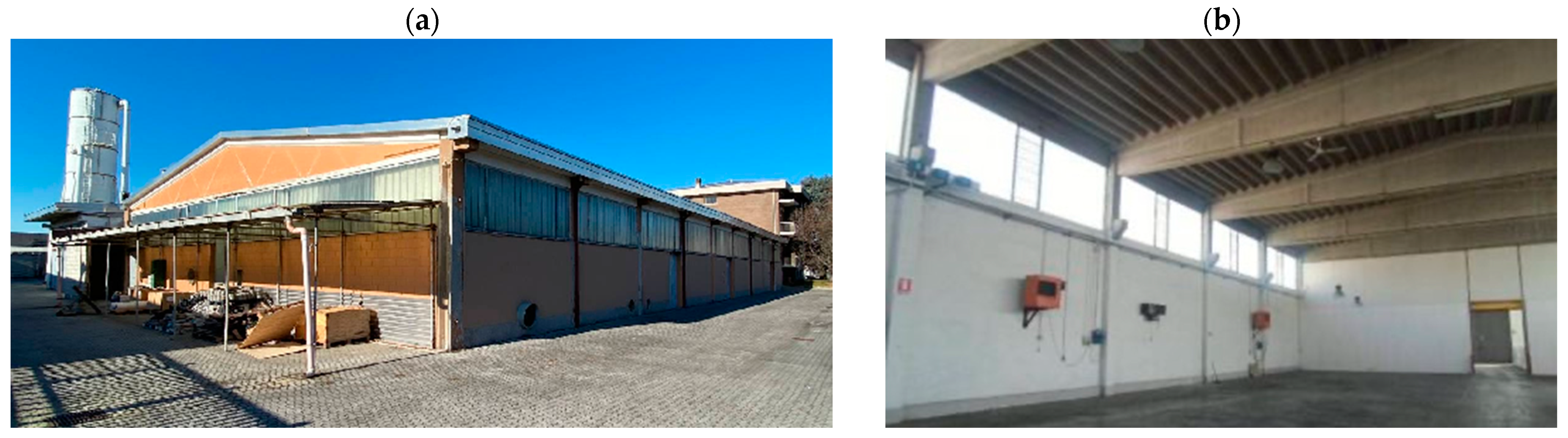
The case study building is a sports hall located in the municipality of Mazzano, Northern Italy, built between 1969 and 1972. Two images of the geometric survey carried out through laser scanning are shown in
Figure 6.
The structure consists of a reinforced concrete frame 28.0 m long, 17.0 m wide, and 8.3 m high. The column grid provides seven spans of 4.0 m and two of 8.5 m in the longitudinal (X) and transversal (Y) directions, respectively. According to the original technical drawings, the columns feature a rectangular 25 × 35 cm cross-section with 4ϕ16 longitudinal steel rebars and stirrups of ϕ8/20 cm (see
Figure 7b). The roof has double-sloped casted RC beams with a height of 80 cm at the supports and 180 cm at the mid-span, including ϕ20 longitudinal rebars and stirrups of ϕ8/20 cm. At the foundation level, the plinths are connected through inverted beams.
An edge RC beam (cross-section 25 × 25 cm with 4ϕ16) links the columns at 4.25 m from the ground, delimiting the bottom masonry infills from the above glazed curtain walls, which are composed of modular elements of 1.35 × 2.00 m.
Based on the geometric parameters and the presence of openings, seven different types of masonry infill can be distinguished (see
Table 1): (1) a bottom full panel in the X direction; (2) a bottom full panel in the Y direction; (3) a top full panel in the Y direction; (4) a bottom panel with an opening (door) in the X direction; (5) a bottom panel with an opening (door) in the Y direction; (6) a bottom panel with an opening for plants in the Y direction; and (7) a top panel with an opening for plants in the Y direction.
Based on a dedicated survey, the material knowledge level LC2, which implies a safety factor for the reduction of characteristic strengths FC = 1.20 [
25], is assumed hereafter for the concrete and steel rebars employed in RC elements.
From the original technical drawings, smooth rebars made of AQ50 steel were used for the RC structural elements. To be on the safe side, the minimum mechanical properties for this obsolete steel grade were adopted [
49]: (i) yield strength
; (ii) ultimate strength
; and (iii) elongation at failure
.
The concrete compressive strength was measured experimentally on seven specimens according to the EN 12390-3:2009 [
50]. The identified compression strength was
, i.e., comparable to that of the modern C16/20, which is assumed hereinafter for FEM calculations. Note that due to the wide spacing of the original stirrups (see
Figure 7b), the confinement effect can be neglected.
Concerning the masonry infills, the removal of a portion of plaster disclosed hollow masonry bricks of 25 cm thickness. Because characterization tests were not carried out, the relevant mechanical properties were defined based on the recommendations of the Commentary Notes (Table C8.5.I) [
26] of the Italian Building Code. To be on the safe side, these parameters were assumed (and reduced through the safety factor FC = 1.35) as follows: (i) compression strength
; (ii) compression elastic modulus
; (iii) shear elastic modulus
; and (iv) shear strength without compression
.
Preliminary pushover analyses were carried out in Midas-Gen 2023 v1.1 [
51] along both the longitudinal (X) and transversal (Y) horizonal directions on the as-built frame.
Beam elements with concentrated plastic hinges were enrolled to model the RC column elements in order to simulate, under the average gravity load,
, flexural yielding-strengths
equal to
and
about the two principal axes. The moment–curvature constitutive parameters were calibrated according to FEMA-356 [
52] for masonry and EC8:2004 [
46] for RC members. In the longitudinal (X) direction, each column was subdivided in two beam elements in order to take into account possible “soft-storey” and “short-column” effects caused by the non-uniformity of the masonry walls in elevation: a first element from the foundation to the end of the full masonry band, and a second aligned with the window openings. A very stiff elastic law with an associated brittle failure threshold of
calibrated according to EC8:2004 [
46] was assigned to the shear hinges located at both end nodes.
Nonlinear “FEMA infill strut-type” Midas elements [
51] were employed to simulate the response of the masonry infills, with the force–displacement parameters of each type of panel (see
Table 1) calibrated according to the Decanini model [
36,
37].
Nonlinear static analyses revealed the inadequacy of the as-built frame to withstand the seismic loads defined by the Italian NTC-2018 standard. For all analysis cases, the “seismic safety factor”
, calculated as the ratio between the seismic acceleration calculated at the building collapse and the peak ground acceleration (PGA) established by the Italian Building Code [
25] for the design new constructions, ranged between 0.29 and 0.65 depending on the adopted loading pattern and direction.
The seismic retrofit through dissipative braces required the following propaedeutic interventions:
Definition of a seismic joint to separate the main frame from that of adjacent structures housing service rooms and plants (see
Figure 7a).
Jacketing of the columns to provide anchoring to the dissipative braces through an external layer of C32/40 concrete, including additional 22ϕ16 longitudinal B450C rebars and stirrups of ϕ10/15 cm (see
Figure 7c). This leads to a significant increase in both flexural strength (
, equal to 374.2
and 497.7
about the two principal axes) and shear strength (
).
For all other columns in the longitudinal (X) direction, the insertion of reinforcing steel plates (mechanical fixing through dowels) at nodes between the columns and the “masonry equivalent struts” (see
Figure 7d) allows a similar shear strength (
) to be achieved also here. According to the Italian Building Code §7.4.4.3, [
25], these elements must be designed to fulfil both strength and ductility requirements for beam–column nodes. Technical details about the proposed solution and the dedicated tool used to perform these calculations can be found at [
53].
Enlargement of the plinths of the strengthened columns (i.e., those with jacketing) to create foundation slabs capable of distributing the huge forces transmitted by the hysteretic braces over a wider footprint (see
Figure 7e).
Insertion of diagonal steel braces at the intrados of the roof to establish a horizontal rigid diaphragm in order to ensure a uniform distribution of seismic forces among the RC columns (see
Figure 7e).
6. Method B1 for Design of the Hysteretic Braces
The refined “Method-B1” adopts a step-by-step procedure (six steps in total) to define the optimized mechanical parameters of the dissipative braces (i.e., hysteretic dampers). With respect to the original “Method-B” of the Italian Building Code [
25], the first novelty is introduced in Step 2, where the design displacement at roof level (
) is identified based on the two performance targets proposed in
Section 2, i.e., protection or damage limitation of drift-sensitive glazed curtain walls and masonry infills. The second novelty is in Step 4, where, in order to ensure a reliable estimation of peak lateral displacements, a more recent formulation of the equivalent viscous damping offered by both the RC frame and the hysteretic dampers is employed.
Step 1—Equivalent elasto-plastic SDOF system of the initial/unbraced frame
In the first step, two pushover analyses were carried out on the initial/unbraced frame along both horizontal directions (X and Y), the first enrolling a “
uniform” distribution of lateral forces and the second a “
modal” distribution, i.e., proportional to the fundamental mode shape. A total of four analyses, two in the X direction and two in the Y direction, were carried out by means of the FEM software Midas-Gen 2023 v1.1 [
51]. The nodes of roof elements were mutually linked through a rigid diaphragm constraint to simulate the stiffening effect of the additional cross-braced steel beams; see the propaedeutic interventions described in
Section 4.
The pushover analyses were interrupted when a local or global collapse was reached. For each horizontal direction, among the two obtained
F-d capacity curves (i.e., base shear vs. the displacement at roof level), the one with lower lateral strength was taken into account for the definition of the equivalent elasto-plastic SDOF system of the initial unbraced frame (see
Figure 9a).
For sake of clarity, all quantities with the suffix “*” are hereinafter related to the equivalent SDOF system of either the real MDOF initial unbraced frame (subscript “F”) or the dissipative diagonal braces (subscript “DB”). Moreover, the subscript “BF” refers to the resulting F-d response of the braced frame (calculated through the superimposition of the two contributions) and to the associated equivalent elastic perfectly plastic system (see
Figure 10).
Assuming that the dynamic response of the initial unbraced frame is governed by the first mode shape, the reduced response of the idealized SDOF (F*-d*) is obtained as: , and , where is the participation factor of the fundamental mode and is the relevant reduced mass. It is worth noting that, as is predictable for single-storey structures, i.e., SDOF systems, is quite close to 1.0: for the longitudinal (X) and for the transversal (Y) initial unbraced frames.
The equivalent bilinear SDOF systems are shown in
Figure 9b for the longitudinal (X) direction and in
Figure 9c for the transversal (Y) one. Relevant parameters are listed in
Table 2, and were identified though the method described in Annex B of the EC8 [
46] (they are enrolled in the Italian Building Code as well). First, the ultimate displacement capacity (
) was identified as the first point, which, in the softening branch of the reduced response, entails a 15% reduction in the maximum lateral strength (
). Afterwards, the yielding force (
) and the corresponding displacement (
) of the ideal elastic-perfectly plastic SDOF system were determined by imposing the equality of the areas subtended by the two plots (see
Figure 9a), i.e., equal energy criterion.
Step 2: Selection of the target displacement
The target displacement at roof level, or performance point (
), of the frame implementing the dissipative braces can be established by employing the inter-storey displacement thresholds (
and
) defined in
Section 2.
For the sake of uniformity and simplicity, a common target displacement for both horizontal directions is established as follows:
where
and
are the two “inter-storey” heights.
At level 2 (suffix L2), for the definition of the displacement threshold of the glazed windows
the following geometric parameters are adopted:
;
; and
. Moreover, it is worth noting that the different displacement thresholds of the masonry infills (i.e.,
and
) at the two levels L1 and L2 reflect the different associated geometric and mechanical parameters (see
Table 1).
Eventually, with respect to the equivalent SDOF system of the braced frame, the displacement target established above can be converted as follows:
Although quite obvious, it is important to check that
and
in order to avoid structural collapse. Moreover, it is worth noting that the established performance point corresponds to a specified design ductility of the main RC frame (
):
where
in the longitudinal (X) and
in the transversal (Y) direction.
Step 3: Selection of the design ductility of the dissipative braces
With reference to the overall response of the dissipative brace (DB), which is composed of the dissipative device (D) plus a stiff beam (B) for the connection to the main frame, the ductility of the equivalent SDOF of the dissipative brace (
) can be selected within the range
[
28,
29]. In the considered case study,
was adopted for both the longitudinal (X) and transversal (Y) frames. In this way, the only remaining unknown design parameter is the yielding strength of the damper (
), as the relevant yielding displacement (
) can be estimated as
leading to
for devices installed along both the longitudinal (X) and transversal (Y) directions.
Step 4: Iterative selection of the yielding force of the dampers
After selecting the target displacement ( for both the X and Y directions) and the ductility of the dissipative braces ( for both cases), the only unknown variable is the relevant yielding force (), which can be calculated through an iterative procedure.
At the generic
jth iteration, a yielding force of the elasto-plastic damper
is assumed, resulting in the following effective vibration period of the braced frame:
where
is the secant or effective stiffness of the braced frame. The overall equivalent viscous damping of the braced frame (
) is then estimated through the weighted average proposed by Priestley [
30]:
where
is the conventional elastic damping of the frame;
is the hysteretic damping developed by the initial unbraced frame estimated through Equation (6) for “large Takeda” systems (i.e., with
a = 65 and
b = 50; see
Section 3);
is the hysteretic damping provided by the hysteretic braces and calculated according to Equation (6) for EPP systems (i.e., with
a = 85 and
b = 60; see
Section 3); and
is the maximum forces developed by the initial unbraced frame. In this regard, it is worth noting that when
, as in the case shown in
Figure 10a,
; otherwise, when
, as in the case shown in
Figure 10b,
.
Step 5: Calculation of the seismic displacement of “BF”
With reference to the ADRS representation of the damped/reduced design spectrum (i.e.,
; see
Figure 10), at the generic
jth iteration the seismic displacement of the braced frame (
) is calculated as
where
is the spectral reduction factor calculated through Priestley’s formula, i.e., Equation (8).
Step 6: Convergence criterion to end the iterative procedure
The iterative procedure is terminated when the discrepancy between the
jth spectral displacement (
) and the design performance point (
) is smaller than a certain tolerance threshold
; in this study,
:
The resulting yielding strength (
) of the dampers at convergence in “Method-B1” are reported in
Table 3; it can be noted that the required damping force (
) is lower along the longitudinal (X) direction (−38.5%) than that along the transversal (Y) frame (
). This reflects the fact that, as reported in
Table 2, the second equivalent SDOF system features a higher reduced mass
(603 tons vs. 500 tons, i.e., +20.6%) with a lower effective stiffness
(22.3 kN/mm vs. 25.0 kN/mm, i.e., −12.1%).
7. Distribution in Elevation of the Damping Force
In this section, the overall damping force of the (equivalent SDOF) hysteretic bracing system, i.e., for the longitudinal (X) and for the transversal (Y) direction, is distributed among the physical dampers installed in the frame. In this regard, it is worth noting that each real/physical DB system is composed of a steel hysteretic damper (D) arranged in series to a beam that acts as a rigid link (RL) to the RC frame. For sake of simplicity, the RLs, in addition to operating far from their yield threshold, are hereinafter assumed to ensure negligible deformations in the overall lateral response of the DB.
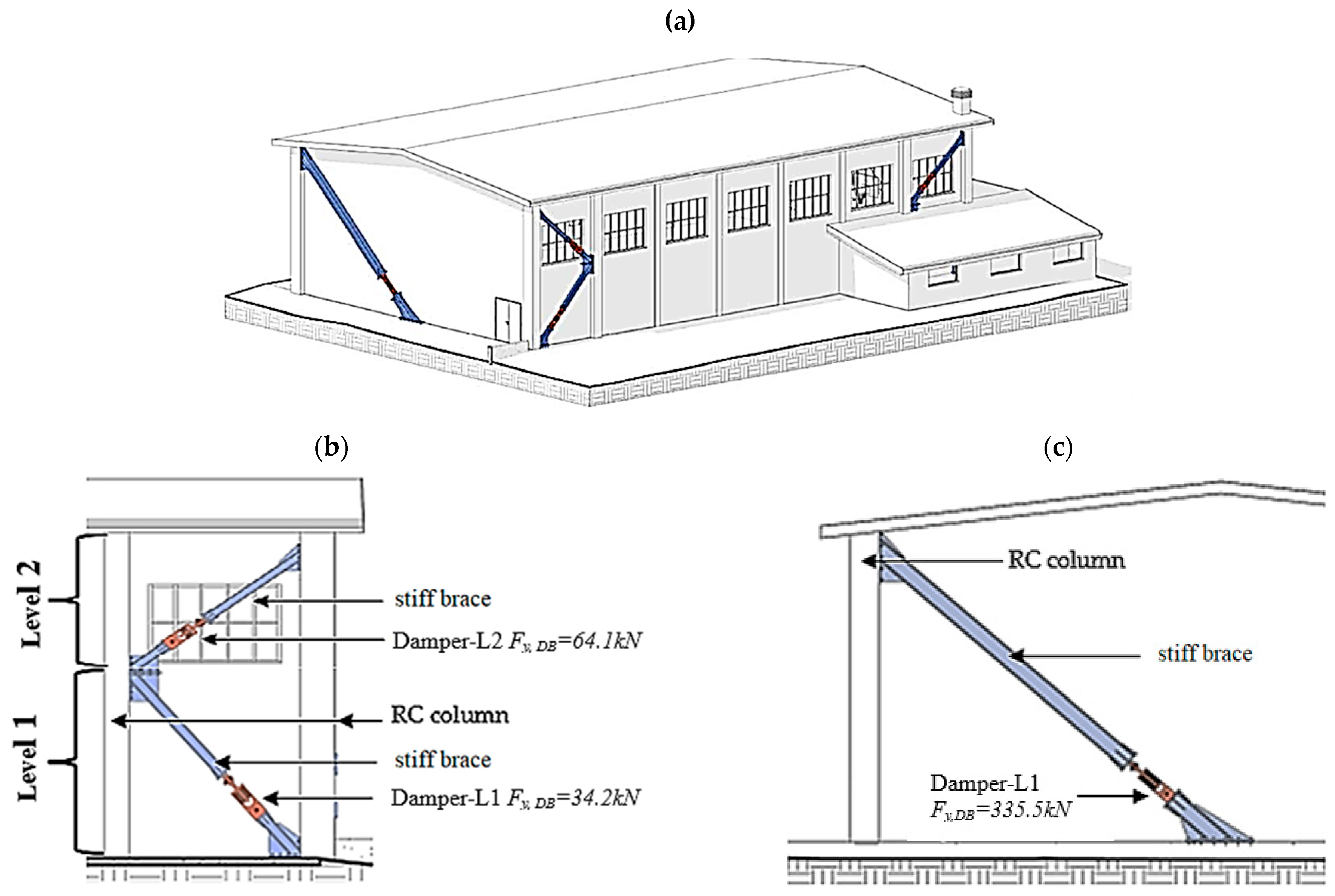
X Direction: in the longitudinal direction, as shown in
Figure 11a, the upper windowed band interrupting the integrity of the masonry infills generates a sharp decrease in the lateral stiffness of the frame. To compensate for this irregularity, the vertical distribution of the overall (equivalent SDOF) damping force is articulated on two levels (see
Figure 12a,b). This means that despite the absence of any intermediate storeys, all columns along the X direction have been virtually divided in two levels (see
Figure 7e and
Figure 11a): level 1 from the foundation to the lower RC edge beam (i.e., from z = 0 m to z = 4.25 m) and level 2 up to the roof edge beam (i.e., from z = 4.25 m to z = 7.50 m).
The Ponzo and Di Cesare criterion [
28,
29] is enrolled within an iterative procedure that aims to identify the dampers’ distribution in elevation that fulfil the two inter-storey displacement targets previously identified (
and
). As shown in
Figure 11b, the pushover analysis on the bare frame (implementing the propaedeutically interventions; see
Section 4) is plotted in terms of the shear force vs. the inter-storey displacement at both levels in order to identify their elastic stiffness (
) and the yielding strength (
). In this regard,
has been calculated as the secant stiffness from 0% to 60% of
while
been identified as the storey shear force associated with the yielding displacement of the MDOF frame (i.e.,
). The obtained level distributions of
and
are shown in
Figure 11c,d, respectively.
To trigger (iteration
) the iterative procedure for the distribution of the dampers on the two levels (subscripts L1 and L2) of the longitudinal (X) frame, these two ratios are calculated as follows [
28,
29]:
Then, the tentative elastic stiffnesses (
and
) and damping forces (
and
) of each single dissipating brace installed at the two levels (L1 and L2) are calculated based on the number of devices (
and
) and the relevant inclination angle (
and
) provided in
Table 4:
NLTH analyses are caried out at each
jth iteration (see
Section 8). The maximum inter-storey lateral displacements (
and
) are calculated and compared with the established performance targets (
and
). In this regard, the damper distribution obtained at the first iteration (
) should already guarantee the achievement of the performance target at roof level, i.e.,
. However, adjustments (i.e., iterations) could be necessary when the maximum inter-storey drifts (i.e.,
and
) are too different from the relevant performance targets (i.e.,
and
). For this purpose, the ratios
and
are iteratively adjusted as follows:
The iterations are interrupted when these two convergence criterions are simultaneously fulfilled: and (with being the convergence threshold; hereinafter, ).
In the considered case study building, two iterations were sufficient. The iterative dampers’ design parameters are reported in
Table 5, while the final layout is shown in
Figure 12.
Y Direction: unlike before, in the transversal direction, thanks to the absence of any significant discontinuity in the masonry infills, it is reasonable to arrange the damping force on a single level (i.e., subscript L1 from foundations to roof). Therefore, only two dampers (
) are installed along very stiff connection braces (with inclination angle
) at both end-sides of the building (see
Figure 12a,c). Each device unit features the following design parameters: (1) yielding force
; (2) elastic stiffness
.
8. NLTH Analyses
In this section, the proposed “Method-B1” is assessed through comparison with the results of nonlinear time-history analyses (NLTHs). These included seven bidirectional independent ground motion records compatible, in average terms, with the ULS design spectrum (see
Section 4). The numerical model of the MDOF braced frame (see
Figure 13a) was developed in Midas-Gen 2023 v1.1 [
51]. The Rayleigh formulation, with both stiffness and damping matrices updated at each time step, was enrolled to account for the structural damping of the frame. The cyclic response of the RC column elements was simulated through concentrated elastic perfectly-plastic hinges with a kinematic hardening rule. Indeed, this is the only option provided by the software to account for the influence of the axial load on the two flexural strengths associated to the cross-section (i.e., the N-M-M domain). Possible shear failures were accounted for by means of elasto-fragile “shear hinges” located at both end nodes of the column elements and featuring a peak strength of 180 kN (see
Section 4).
Nonlinear “FEMA infill strut type” elements (see [
51] for detailed info) with an associated “Takeda hysteretic rule” were employed to simulate the equivalent struts of the masonry infills with parameters calibrated according to the Decanini model (see
Table 1).
To model the dampers, the Midas elements “
Seismic Control Device—Type 2” with an associated “
Degrading Bilinear Model” were adopted. However, both the “
plastic hardening” and “
stiffness degrading” options were de-activated by setting
and
for all dissipative elements (see [
51] for detailed info), while other dampers’ design parameters were set according to
Table 5. In this regard,
Figure 13b proves that the dampers’ hysteretic loops calculated for one of the seven NLTH analyses are compliant with the design force–displacement response for all three typologies of device (two in the X direction and one in the Y direction). In particular, it can be noted that the dampers installed along the transversal (Y) direction (blue plot) experience the highest axial deformation; (about 21 mm). On the contrary, in the other direction the lateral displacement demand is split among the dampers installed at the first (L1) and second (L2) levels; (about 8 mm and 11 mm, respectively).
Moreover,
Figure 13c shows the relevant time histories of the accumulated energies. At the end of the ground motion, the dampers dissipate about 50% of the total input energy of the earthquake.
To assess the suitability of the refined “Method-B1” for defining a damper’s layout tailored to the presence of masonry infills and glazed curtain walls, the peak inter-storey displacements (
and
) are compared with the relevant performance targets (
and
). According to the Italian Building Code [
25], the two peak values were defined in average terms, i.e., the mean value of the seven NLTHs, allowing us to highlight the following outcomes:
In the longitudinal direction (X), the dynamic response of the braced frame calculated at the first iteration (
j = 1—see
Table 5) is already satisfactory. Indeed,
and
, proving the integrity of both drift-sensitive components. However, the maximum displacement at roof level (
+
) is significantly lower (−31.5%) than the target value (
). This can be justified by the strong discontinuity of the frame lateral stiffness, which is not yet compensated by the hysteretic braces at the first iteration.
In the same direction, in the second iteration (
j = 2) the dampers’ effective stiffness and yielding strength at the first level (i.e., L1) are decreased (
and
, see
Table 5) with the purpose of increasing the relevant inter-storey drift. Indeed, eventually
, which is sufficiently close to
. At the upper level (i.e., L2) the dampers’ parameters were not changed; predictably, the offered dynamic response was
, leading to a total roof displacement of 25.1 mm, i.e., −7.0% with respect to
.
In the transversal direction (Y), the dampers’ parameters were not varied during the two simulations as, despite the single layer of dampers, both performance targets were achieved in the first iteration. Indeed, both and were close enough to the relevant targets (i.e., and , respectively). The maximum roof displacement was 25.3 mm (i.e., −6.3% with respect to ).
9. Conclusions
This paper presents a refined design procedure for the seismic retrofitting of single-storey RC frames, e.g., warehouses, logistic centers, and sports halls, by means of hysteretic braces. In particular, with respect to the provisions of “Method-B” of the Italian Building Code, two novelties are introduced:
- (1)
Definition of two performance targets to tailor retrofitting interventions to the protection and/or damage limitation of the “drift-sensitive” masonry infills and glazed curtain walls that typically bound these buildings. These targets are expressed in terms of inter-storey displacement thresholds that are calibrated depending on their geometric and mechanical parameters.
- (2)
Adoption of a more recent and accurate formulation for estimating the equivalent viscous damping developed both by the main RC frame and the dissipative braces during seismic shaking.
The suitability of this design framework, called “Method-B1”, has been proven through application to a case study building, namely, a sports hall located in Northern Italy built in the early 1970s and affected by important structural deficiencies. First, propaedeutic interventions were proposed, see
Section 4. Afterwards, the six steps of “Method-B1” were carried out by means of iterative displacement response spectrum analyses in order to identify the dampers’ layout that fulfill the two performance targets.
In the longitudinal (X) direction, the upper windowed band interrupting the integrity of the masonry infills causes a sharp decrease in the frame lateral stiffness. Although the building features only one storey, optimized dampers capable of compensating for this irregularity were arranged on two levels: the first level (L1) below the windows, and the second level (L2) horizontally aligned with the same. Based on the mechanical and geometric properties of both masonry infills and glazed windows, it was possible to identify two inter-storey displacement thresholds: (1) for level L1, ; and (2) for level L2, . At roof level, the lateral target displacement was set to .
On the contrary, in the transversal (Y) direction, thanks to the absence of any significant discontinuity in the masonry infills, the hysteretic dampers were installed on a single level; note that in this case L1 spans from the foundations to the roof.
Having identified the optimal damper layout (i.e., the number of devices, their yield strength, and a ductility level that allows the attainment of both design targets), the effectiveness of the proposed solution was proven through comparison with the results of NLTH analyses. The following outcomes can be concluded:
In the longitudinal (X) direction, two design iterations were performed. The first set of design parameters used for the dampers, despite ensuring the integrity of the two “drift-sensitive” components, resulted in a maximum roof displacement significantly lower (−31%) than the target value. In the second iteration, the dampers’ effective stiffness and yielding strength at level L1 were decreased to compensate for the higher rigidity of the bottom masonry infills. Although slightly affecting the integrity of the same, this allowed us to get closer to the displacement target ( vs. ). At level L2, the dampers’ parameters were fixed in the first iteration, as the calculated response was coincident with the target (). The resulting overall lateral displacement at roof level was equal to (i.e., −7.0% respect to ).
In the transversal (Y) direction, the optimal damper parameters were identified in the first iteration, as despite the single layer of dampers both performance targets were met ( and were close enough to the relevant targets, i.e., and , respectively). The maximum calculated roof displacement was 25.3 mm, i.e., −6.3% with respect to .
Based on these results, we can conclude that the proposed “Method-B1” allows: (1) the attainment of certain protection levels for drift-sensitive building components such as masonry infills and glazed curtainwalls; (2) an accurate prediction of the overall lateral displacement of the frame, i.e., at roof level, during severe ULS seismic events.
In future developments of this study, a wider range of seismic scenarios, including vertical ground accelerations and “pulse-like” seismic events, will be employed for further assessments of “Method-B1”.


