Article

An Improved Crack Identification Method for Asphalt Concrete Pavement

School of Information Engineering, Chang’an University, Xi’an 710018, China
*
Author to whom correspondence should be addressed.
Appl. Sci. 2023, 13(15), 8696; https://doi.org/10.3390/app13158696
Submission received: 17 June 2023 / Revised: 16 July 2023 / Accepted: 20 July 2023 / Published: 27 July 2023

Abstract

:
The results of high-precision asphalt concrete pavement crack identification can provide help for pavement maintenance. Therefore, methods of image feature enhancement and crack identification of asphalt concrete pavement cracks are proposed. First of all, we used an industrial CCD camera mounted on a vehicle to collect an asphalt concrete pavement crack image. Then, after using the NeighShrink algorithm to denoise the acquired image, a fractional differential image enhancement algorithm was designed based on image feature blocks to enhance the image features. On this basis, crack characteristics were segmented and processed by watershed algorithm. Through crack direction identification and crack parameter extraction, crack distribution direction, crack length and width and other parameters of asphalt concrete pavement were obtained in order to achieve accurate identification of asphalt concrete pavement cracks. The experiment found that this method can effectively remove noise information from asphalt concrete crack images; after applying this method, the image entropy value of each image was improved, with a minimum improvement of 0.38 and a maximum improvement of 1.98. The time consumed by this method in identifying cracks in asphalt concrete pavement varied between 1.4 s and 2.4 s. When identifying the length of cracks in asphalt concrete pavement, the maximum deviation value was only 0.47 mm; when identifying the width of cracks in asphalt concrete pavement, the maximum deviation value was only 0.31 mm. The above results indicate that by enhancing the image features of asphalt concrete cracks, this method achieves more accurate identification results for crack distribution direction, length and width values, with high identification efficiency and good application effect.

1. Introduction

In 2012, the mileage target and total completed mileage target of China’s planned national highway project reached nearly 100,000 km, and the total planned mileage target in 2018 also accumulated about 143,000 km. Statistics from the Ministry of Transport show that by 26 April 2022, a national highway network was basically formed, with highways as the skeleton, ordinary trunk lines as the veins and rural roads as the basis [1].
Asphalt concrete pavement is a common road material, but with the passage of time and the increase in traffic load, asphalt concrete pavement is prone to cracks. These cracks not only affect the aesthetics and comfort of the road, but may also lead to further damage and safety hazards. Therefore, timely identification and repair of cracks in asphalt concrete pavement is very important. At present, the speed of highway construction is gradually slowing down, and the bearing capacity of the road is gradually decreasing, so it is very important to maintain the highways. At present, among all kinds of pavement diseases, cracks are still one of the most common, are the easiest to occur and are potentially harmful subgrade diseases in the pavement structure [2]. Therefore, the country has put forward a new goal of highway construction, which requires that under the premise of not affecting the traffic operation, through the analysis, detection and identification of highway cracks, road conditions can be accurately and quickly mastered, and the automatic detection of pavement models can be realized.
At present, the most traditional road detection work is usually completed by manual field walk-through. This detection method is generally carried out by professionals to detect pavement defects, analyze the severity of the road and carry out evaluation [3]. Due to the random distribution and wide space characteristics of pavement cracks, this detection method is very labor-intensive and requires many material resources, and the dangerous sections need to be tightly sealed when collecting and detecting in the field, which causes a certain degree of traffic safety hazards; therefore, it is difficult to achieve automatic pavement crack detection using the above traditional artificial pavement crack detection technology [4]. Now, there are also many domestic and foreign scholars studying pavement crack identification methods, such as Winkelmaier et al., who put forward the method of terrain-guided UAV to identify tension cracks in open pit mines [5]. The method uses a UAV to collect ground crack images; the UAV flies at a constant altitude according to a flight path preprogrammed to generate mosaic and depth-map images. Next, the workbench, capture platform and channel are automatically identified and represented by their axes. Then, waypoints from each axis are sequentially uploaded to the UAV to scan the corresponding area with high resolution. Then, these high-resolution images are used to depict tension cracks and realize crack identification. However, the cost of this method is too high, and its application scope is small. Palermo et al. proposed a multimodal robot vision crack detection method, which uses videos/photos taken by a vehicle-borne robot camera to locate cracks in a remote environment [6]. The region of interest is identified and then explored by robots with tactile sensors. Faster R-CNN object detection is used to identify the location of potential cracks. Random forest classifier is used for tactile identification of cracks to confirm the existence of cracks, but the method is not accurate enough to identify cracks. Mubashshira et al. proposed an unsupervised method for pavement crack detection. After collecting the pavement crack image, this method uses a K-means clustering algorithm and Otsu threshold method to segment and realize crack identification [7]. However, this method does not preprocess the pavement crack image, resulting in insufficient identification accuracy. Rui et al. put forward attribute fusion technology based on principal component analysis in their crack identification method [8]. This method uses the principal component analysis method to analyze the principal components in a pavement crack image to achieve pavement crack identification. However, this method is affected by the selection of parameters of the principal component analysis algorithm, resulting in a poor application effect. Vega et al. proposed a fractal feature identification method for multimode and multiscale images of fracture networks [9]. This method collects a group of multimode and multiscale images of fracture samples and analogues, and calculates the fractal dimension and length distribution of fracture networks for each image data set. The pavement crack identification results are obtained based on the scale, samples and order of magnitude. However, there is a deviation in the calculation of the fractal dimension of the crack grid by this method, which leads to its poor application effect.
In many road management systems, road crack data sometimes comprise the sole criterion for determining road quality. For road management systems used by local governments and urban areas, it is difficult to measure road friction and roughness due to a lack of equipment, high cost or relatively low efficiency. This also leads to an urgent need for effective road crack identification and detection technology in the field of road management. Therefore, in response to the shortcomings of traditional methods, with the aim of effectively detecting longitudinal cracks, transverse cracks, oblique cracks and net-shaped cracks, this paper proposes the methods of image feature enhancement and crack identification of asphalt concrete pavement cracks, in order to improve the level of asphalt concrete pavement crack identification technology.
The rest of this paper is arranged as follows. In Section 2, we give the specific methods of image feature enhancement and crack identification in this paper. Section 3 gives the experimental setup and some experimental results to verify the proposed methods. Finally, Section 4 concludes this paper.

2. Methodology

2.1. Image Feature Enhancement Method of Asphalt Concrete Pavement Cracks

After collecting images of asphalt concrete pavement using a vehicle-mounted CCD camera, the image features are enhanced to provide a reliable image foundation for subsequent pavement crack identification.

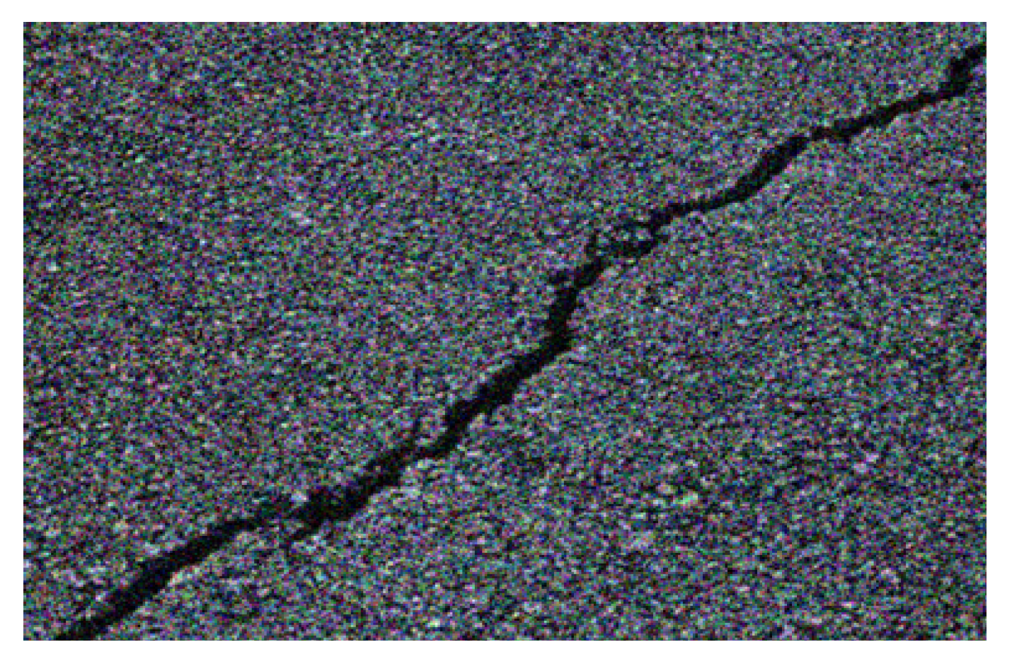
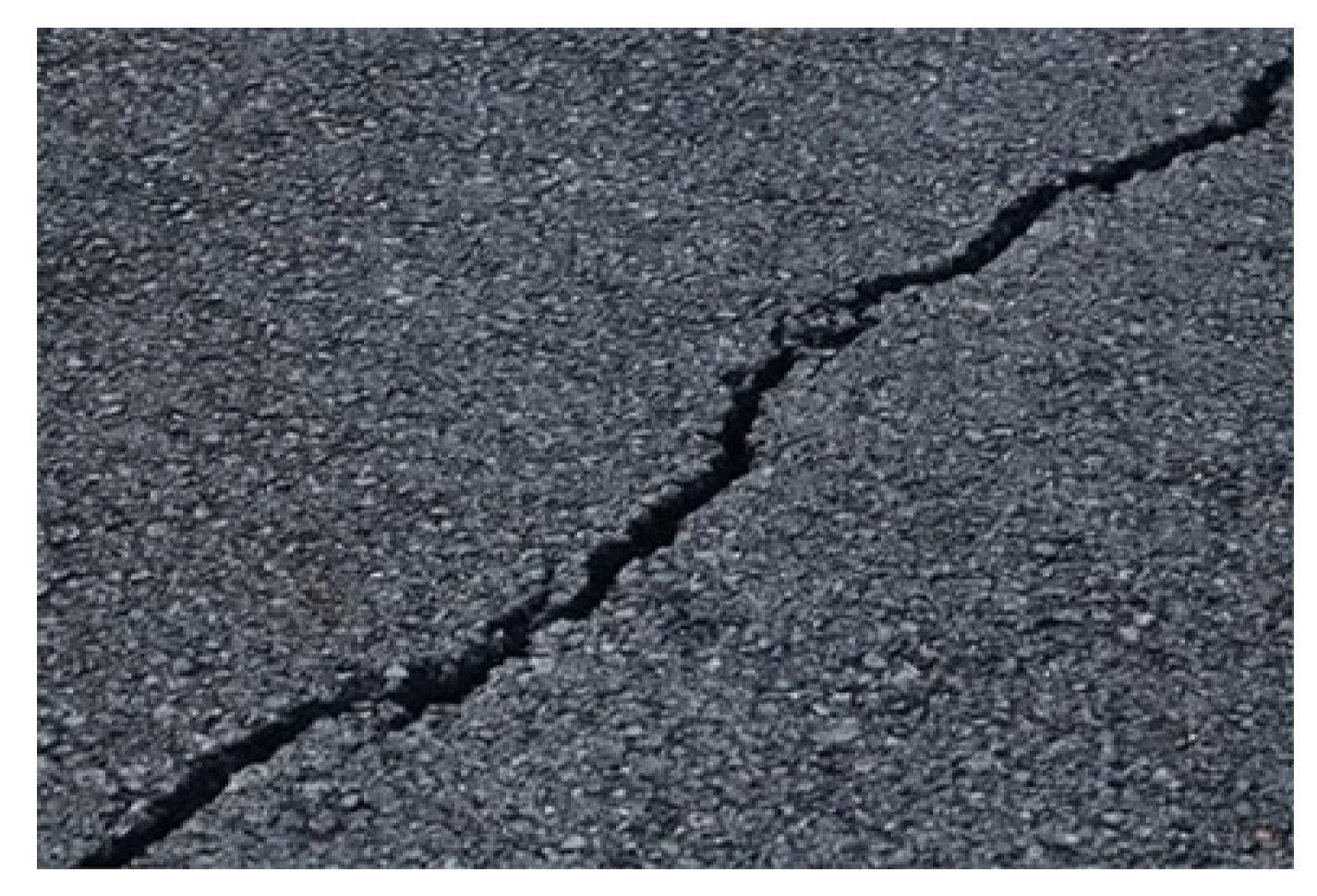
2.1.1. Pavement Crack Image Denoising Preprocessing

In the process of image acquisition and transmission, there will be image dislocation, band noise, stripe noise and so on. In order to make the cracks in the asphalt concrete pavement crack image clearer and identify cracks more accurately, the image needs to be denoised [10,11,12]. Here, the NeighShrink algorithm is used to implement image preprocessing.
The purpose of denoising is to eliminate the noise present in the image, making it clearer and easier to analyze and process. When collecting asphalt concrete pavement crack images, due to environmental conditions, changes in light, limitations of the image sensor itself and other factors, the image may be subject to various types of noise interference, such as Gaussian noise, Salt-and-pepper noise, etc.
By applying denoising algorithms such as the NeighShrink algorithm, the noise level in the image can be effectively reduced, and the image quality can be improved. Denoising processing helps to reduce the interference of noise on image features, enabling subsequent image enhancement, segmentation and feature extraction algorithms to more accurately identify and analyze crack features. This can improve the precise identification and parameter extraction capabilities of asphalt concrete pavement cracks, providing more reliable data support for pavement maintenance and repair.
The detailed process is as follows:
Set Q as the image of asphalt concrete pavement cracks observed, and its expression equation is as follows:
U = κ + E
where E represents Gaussian white noise and κ indicates the crack information of asphalt concrete pavement without noise.
Set j , g to represent the scale and direction of the asphalt concrete pavement crack image, respectively; the non-downsampled contour wave transform coefficient of the image on this scale and in this direction is U j , g . the neighborhood of the transformation coefficient is determined by B j , g . Based on U j , g , calculate neighborhood B j , g , the wavelet transform coefficient of which is expressed as follows:
D j , g = ( i , l ) P U i , l 2
where D j , g represents wavelet transform coefficients of neighborhood B j , g and P represents the total number of wavelet coefficients in the image sub-band.
Based on Equation (2), the image is denoised, and the expression equation is as follows:
κ j , g = D j , g ϑ 2 D j , g + Q j , g
where κ j , g represents an image without noise, where the scale and direction are j and g , respectively; ϑ 2 represents the standard deviation of the image signal; and Q j , g indicates that the initial scale and direction are j and g , respectively, of the asphalt concrete pavement crack image.
After the above steps, the preprocessing of asphalt concrete pavement crack image denoising is realized.

2.1.2. Fractional Differential Image Feature Enhancement Algorithm Based on Image Feature Segmentation

When the pixels in the asphalt concrete pavement crack image signal are adjacent in the spatial domain, they show a strong correlation, which contains a lot of structural information about the target image [13,14]. According to this information, the image is divided into image blocks with similar structure information, then the fractional order differential order is set according to the proportion of each feature image block and, finally, the order is substituted into the mask operator for calculation.
Step 1: Conduct the image structure feature segmentation method as follows.
According to the structural characteristics, the original asphalt concrete pavement crack image is divided into image blocks with similar image information but different shapes. The structural features of image blocks are measured by the mean and variance of gray levels. Divide the image into M × N . Each square contains basic image information, and blocks with similar information in the image are combined to form a new image block. During the merging process, calculate the variance of the original image block after merging with each adjacent basic image block, and select the image block with the smallest variance after merging as the new image block, that is, the original image block that is most similar to the basic image block structure information, and then continue to search for a new basic image block for merging. Set a threshold value for the image block. When the variance of the image block exceeds this threshold value, the merging of the current image block will be stopped and the merging of the next image block will start. Because the variance of the merged image blocks needs to be calculated each time when searching for the most similar basic image blocks, the search speed is slow. In response to this issue, this study simplifies the search process by following Theorem 1, which states that the variance between the basic image block and the original image block is the minimum value.
For samples Y and X s ( s = 1 , 2 , , n ) , k , μ 0 and Υ 0 2 are sample size, mean and variance of Y , respectively, and R , μ s and Υ s 2 are sample size, mean and variance of X s ( s = 1 , 2 , , n ) , respectively. From sample X s ( s = 1 , 2 , , n ) , select a group, and from sample Y , form a new sample Z ; the sample size, mean and variance of new sample Z are k + R , μ 0 and Υ 0 2 , respectively. Among k , m and Υ 0 2 , μ 0 are constants, and μ s and Υ s 2 are variables. If in sample X s ( s = 1 , 2 , , n ) , variables μ s and Υ s 2 satisfy the value of the expression ( m 1 ) Υ s 2 + m k m + k ( μ s μ 0 ) 2 as the smallest, then Y and X s ( s = 1 , 2 , , n ) form the new sample Z in R + k , and the sample variance Υ 0 2 is minimum.
The variance of sample Y is calculated as follows:
Υ 0 2 = i = 1 k ( y i μ 0 ) 2 k 1
The variance of sample X s ( s = 1 , 2 , , n ) is calculated as follows:
Υ s 2 = i = 1 R ( x i μ s ) 2 R 1
The variance calculation equation of the new sample Z is as follows:
Υ 0 2 = i = 1 k + R ( z i μ 0 ) 2 k + R 1
Due to the fact that the new sample Z is created by Y and X s ( s = 1 , 2 , , n ) , it is composed of:
i = 1 k + R ( z i μ 0 ) 2 = i = 1 k ( y i μ 0 ) + i = k + 1 k + R ( x i μ 0 ) 2
( k + R ) μ 0 = k μ 0 + R μ s
Equation (7) can be converted to:
Υ 0 2 = i = 1 k ( y i μ 0 ) 2 + i = k + 1 k + R ( x i μ 0 ) 2 k + R 1
Set λ = R R + k , Δ μ = μ s μ 0 , we can obtain from Equation (8):
μ 0 = μ 0 + λ Δ μ
According to the above equations, it can be deduced that:
( y i μ 0 ) 2 = ( y i μ 0 + λ Δ μ ) ( x i μ 0 ) 2 = ( x i μ s + ( 1 λ ) Δ μ )
According to Equation (11):
i = 1 k ( y i μ 0 ) 2 = i = 1 k ( y i μ 0 ) 2 + k ( λ Δ μ ) 2 i = k + 1 k + R ( x i μ 0 ) 2 = i = k + 1 k + R ( x i μ s + R ( 1 λ Δ μ ) ) 2
Substitute Equation (12) into (9) to obtain:
Υ 0 2 = ( k 1 ) Υ 0 2 + ( R 1 ) Υ s 2 k + R 1 + R k ( μ s μ 0 ) 2 R + k
The image block corresponding to the minimum value of Equation (11) is taken as a new image to complete the block processing of an asphalt concrete pavement crack image.
Step 2: Conduct fractional differential image enhancement as follows.
After image block processing, the basic image blocks with similar structure information are merged into a new image block, and the gray variance in each image block is basically the same. If the proportion of image blocks is large, the gray change in the image block is small, otherwise, the gray change in the image block is large. At the same time, because the human eye is more sensitive to the change in the gray value, the area with a large proportion is considered as the background of the image, while the area with a small proportion is considered as the subject of interest in the image. In order to highlight the image body, the image blocks in this area should be of a higher order, while the background should be of a lower order.
The steps for enhancing processing are as follows:
Step 1: Calculate the proportion of image blocks in the whole image according to the result of image blocks λ i .
Step 2: The proportion of image block area λ i and fractional differential order v correspond within the range of (0, 1), meeting the requirement that large image areas correspond to small v value, and the small image area corresponds to the large v value. The calculation equation given in this paper is shown in Equation (12). Parameters in Equation (12) ξ are the differential order and the upper limit of v , and meet 0 < ξ < 1 .
v i = ξ ln ( λ i ) ln ( 1 / ( M × N ) )
Step 3: Calculate the fractional order according to Equation (14), and make the order correspond to the pixel points in the image block to obtain the order matrix, whose size is consistent with the image.
Step 4: Because blocking may cause large image blocks adjacent to small image blocks, resulting in too large a difference in fractional differential order corresponding to regional edges and distortion at the junction of image blocks, neighborhood average processing of the order matrix is required [14]. For example, Use 5 × 5 to sum an element of the matrix and its surrounding 24 elements and divide by the number of elements 25, and take the value obtained as the element of the new order matrix.
Step 5: Substitute the value in the order matrix into the mask operator to operate the original image.
When we finish the above steps, the image features of asphalt concrete cracks are enhanced.

2.2. Segmentation Processing of Crack Image Based on Watershed Algorithm

The idea of watershed segmentation originates from the surface model in topography, and the segmented asphalt concrete pavement crack image is regarded as a topological surface [15,16,17]. In the gray image, each pixel’s gray value corresponds to the height in the terrain, and each local minimum value and its influence area become a catchment basin. It is envisaged that a hole will be pierced in each bottom valley area, and the water will flow upward from the hole, gradually immersing the whole terrain in the water. Then, the water from different bottom valleys will build dams one by one, forming the watershed of the included area. These watersheds also correspond to the boundary outline of the topology and surface image. The watershed is the maximum point of the image. In practical applications, in order to obtain the edge contour of the image, the input image is a gradient grayscale image I ( x , y ) , where x and y comprise the image pixel, and its gradient image expression equation is:
F ( I ) = I S E I Θ S E
In Equation (15), is the expansion operator, Θ is the corrosion operator and S E is a morphological structural element.
Watershed division steps are as follows:
Step 1: Scan the crack image of gradient asphalt concrete pavement F ( I ) , and find the minimum value. ( x , y ) F ( I ) , where neighborhood set N ( x , y ) , x = x 1 , x , x + 1 , y = y 1 , y , y + 1 . If F ( x , y ) > F ( x , y ) , x , y N ( x , y ) , then F ( x , y ) is marked as non-minimum, first-in, first-out queue Q ; when Q is not empty, its first element will be queued. Set F ( x , y ) as the first queue element of Q ; if F ( x , y ) marks as empty, x , y N ( x , y ) and F ( x , y ) = F ( x , y ) , then G ( x , y ) is marked as minimum and queued Q .
Step 2: Place the found minimum adjacent pixels in an orderly queue Q . Scanning gradient asphalt concrete pavement crack image F ( I ) , set, if F ( x , y ) marks as empty, then F ( x , y ) C B i , F ( x , y ) in queue Q . If Q is non-empty, the first element is out of the column. Set F ( x , y ) as the first queue element of Q ; if F ( x , y ) marks as empty, x , y N ( x , y ) , then F ( x , y ) in queue Q ; otherwise G ( x , y ) is marked and placed in Q .
Step 3: Queue Q , where the pixel containing the smallest gray value, is listed. Set F ( x , y ) as the first queue element of Q , if F ( x , y ) marks as empty, x , y N ( x , y ) and F ( x , y ) C B k ( k = 1 , 2 , , i ) , then F ( x , y ) C B k .
Because of the subtle gradient change in the image’s gray level and the influence of noise, the problem of oversegmentation can occur very easily [18]. Eliminating oversegmentation is mainly performed to limit the number of regions. Merging similar regions can solve the problem of oversegmentation. The region-merging algorithm often uses the gray difference between a point and its surrounding neighborhood as the merging criterion. This method is more suitable for images with large gray changes. For the crack image, the crack information is weak, accounting for a small proportion in the whole image, and the image gray level changes relatively gently, which is not suitable for use. To solve this problem, this paper proposes an improved similar-region-merging algorithm. The steps are as follows:
Step 1: Set ς i , σ i ( i = 1 , 2 , , m ) to represent the mean value and standard deviation of pixels in the region, respectively.
Step 2: Consolidation criteria for similar areas are as follows:
ς 1 ς 2 α
s = ς 1 ς 2 1 σ p 2 ( 1 / q 1 ) + ( 1 / q 2 ) β
σ p 2 = ( q 1 1 ) σ 1 2 + ( q 2 1 ) σ 2 2 / q 1 + q 2 2
Among them, q i is the number of image pixels in the region; and α and β are given by the statistical characteristics of the image.
If σ p 2 = 0 , then any two regions that meet Equation (13) are considered to be similar regions; otherwise, two regions that meet Equation (14) are considered to be similar regions.
Step 3: If there are multiple similar areas, make them the most similar, that is, merge the adjacent regions with the lowest s value.
Step 4: Select a new region from the remaining regions and execute from step 1 until all adjacent regions are merged.
In order to improve the speed of region merging, this paper uses region adjacency graph. Use 0 or 1 to represent the adjacency between the current processing area and an area through two states, store it in a table and update the adjacency with the merging process.
After the above steps, the concrete crack image is segmented to obtain the crack characteristics in the image.

2.3. Classification and Identification Method of Cracks

2.3.1. Crack Direction Identification

Based on the segmented asphalt concrete pavement crack image, the crack direction in the image is recognized. The cracks of highway concrete pavement can be divided into linear cracks and net-shaped cracks, and the former can be subdivided into transverse, longitudinal and oblique cracks [19,20,21]. Because the disease parameters to be extracted from net-shaped and linear cracks are different, the cracks must be classified first, using the classification algorithm. This paper classifies the cracks in two steps. First, the method of marking the background connected region curve is used to distinguish the linear cracks from the net-shaped cracks, and then the image projection method is used to classify the linear cracks.
The method of marking connected domain is used to distinguish linear and net-shaped cracks. The image background area is divided into more than three connected domains by cracks, while the background of linear cracks is generally divided into two connected domains. Finding the number of background connected components from the labeling algorithm N , compare it with the threshold value T n . If N is greater than T n , it is a net-shaped crack; if the reverse, it is a linear crack.
If the pixel size of the crack image is M × N , the pixel value of line i , column j is I ( i , j ) and projections on X direction and Y direction are X ( j ) and Y ( j ) , there are:
X ( j ) = i = 1 M I ( i , j ) , j = 1 , 2 , , N Y ( i ) = i = 1 N I ( i , j ) , i = 1 , 2 , , M
In order to automatically identify the linear crack category, the difference operation is performed on the horizontal and vertical projection sequences, and the maximum difference value is calculated:
Q r = max X r ( j + 1 ) X r ( j )
Q c = max Y c ( i + 1 ) Y c ( i )
T = Q r Q c
Among them, Q r is the maximum difference value on the horizontal projection, Q c is the maximum difference value on the vertical projection, X r ( j ) and X r ( j + 1 ) are values adjacent to X ( j ) , and Y c ( i ) and Y c ( i + 1 ) are values adjacent to Y ( i ) .
For transverse cracks, Q c is much greater than Q r ; for longitudinal cracks, Q r is much greater than Q c ; and for diagonal cracks, the values of Q c and Q r are equivalent. Set a threshold value for transverse and longitudinal cracks T 0 ; when T is greater than T 0 , the crack is horizontal and vertical; otherwise, it is ab inclined crack. Finally, compare the values of Q c and Q r ; this can be used to determine whether the crack is transverse or longitudinal.
After the above steps, the identification of the distribution types of cracks in asphalt concrete pavement is realized. However, it is far from enough to only identify the types of cracks in asphalt concrete pavement. It is also necessary to identify the width, area, etc., of the cracks, in order to provide detailed information for the maintenance of asphalt concrete pavement.

2.3.2. Extraction of Crack Parameters

When analyzing linear crack parameters, this study mainly focuses on the length and width of linear cracks [22,23]. For net-shaped cracks, the main analysis is the area of road surface damage.
① Linear crack treatment.
The calculation method of linear crack length is to refine the crack first, and then calculate its length; the calculation of width is the average width obtained by dividing the crack area by the length after obtaining the crack area. Extract the crack skeleton from the segmented crack image and refine it into a single-pixel crack image. The line length after thinning is the length of the crack. The corresponding true length between adjacent pixels can be calculated separately, and then the distance between all adjacent pixels can be summed to form the crack length.
Assume that the refined crack is composed of n , composed of consecutive pixels; ( x i , y i ) and ( x i + 1 , y i + 1 ) represent two adjacent pixels, S H is the scale factor in the horizontal direction, S V is the scale factor in the vertical direction, L D is the distance between the two adjacent pixels and L is the length of the whole crack, so that the length of the linear crack can be obtained. The calculation equation is as follows:
L D = ( x i x i + 1 ) S H 2 + ( y i y i + 1 ) S V 2
L = i = 1 n 1 L D
② Calculate average crack width.
If the actual area represented by a pixel in the crack image is S , and the pixel occupied by the crack is N , then the total crack area A is:
A = S × N
When the crack length and crack area are known, the average width W of the crack can be obtained:
W = A / L
③ Net-shaped crack treatment.
The damage area of a net-shaped crack is obtained by the method of finding the minimum junction rectangle of the crack image. After obtaining the length and width of its minimum circumscribed rectangle, according to Equations (20) and (21), we can obtain the length corresponding to the real area L and width W , and the damaged area of the pavement can be obtained:
S = L W

3. Experiment and Result Analysis

The experiment took a certain area of asphalt concrete pavement as the experimental object and collected crack images of the asphalt concrete pavement using a CCD camera installed on a vehicle. The collected images were then feature-enhanced and crack-recognized, verifying the practical application effect of this method. The CCD camera model was SBC-2300P, and the vehicle was a regular off-road vehicle. The experiment collected a total of 45,322 image data, mainly including two types of images, each with a size of 640 × 480 pixels or 1024 × 768 pixels. We divided the data set into two equal parts, one as the training set and the other as the test set. Taking one of the crack images as an example, the collection results are shown in Figure 1.
It can be seen from the analysis of Figure 1 that this method can effectively collect an image of asphalt concrete pavement cracks, and the cracks in the image are relatively clear, but there are interference noise points in the image.
Taking Figure 1 as the experimental object, the method in this paper was used to carry out noise removal pretreatment, thus verifying the noise removal effect of the method in this paper on asphalt concrete pavement cracks. The results are shown in Figure 2.
It can be seen from the analysis of Figure 2 that when the method in this paper is used to denoise the asphalt concrete pavement crack image, the crack information in the image is completely retained, the interference noise in the image is removed and the pavement cracks are more obvious. This result shows that the method in this paper can effectively denoise the image.
When we finish the image denoising, and then performed feature enhancement processing. The result of feature enhancement is shown in Figure 3.
It can be seen from the analysis of Figure 3 that after using the method in this paper to enhance the characteristics of the asphalt concrete pavement crack image, the cracks in the image are clearer; in particular, the crack edge trend and the small cracks are more obvious. The above results show that after the seam image feature enhancement processing is completed using the method in this paper, the fine texture of the crack in the image is clearer; the method has a strong image enhancement effect.
Image entropy is a measure that reflects the richness of image information from the perspective of information theory. The size of image entropy reflects the amount of information carried by the image. Generally, the larger the image entropy is, the richer the information is, and the higher the image quality is. The image entropy is taken as the performance index to measure the method in this paper to enhance the image performance of asphalt concrete pavement cracks. Taking 11 asphalt concrete pavement images as experimental objects, the method in this paper was used to enhance the image features, and the image entropy changes of asphalt concrete pavement images before and after feature enhancement were compared and analyzed. The results are shown in Table 1.
According to Table 1, after using the method proposed in this paper to enhance the features of the 11 asphalt concrete pavement images, the image entropy values of each image were improved, with the minimum value of improvement being 0.38 and the maximum value being 1.98. The results show that this method can effectively enhance an image of asphalt concrete pavement, improve the image entropy of the asphalt concrete pavement image and make the internal crack information of the asphalt concrete pavement image more obvious.
Taking an asphalt concrete pavement image as the experimental object, we used this method to extract its features. The results are shown in Figure 4.
It can be seen from the analysis of Figure 4 that the method in this paper is used to extract the features of asphalt concrete pavement images; the extracted crack features are relatively obvious, and the relatively small cracks are also extracted. This result shows that the method in this paper has a good ability to extract the crack features of asphalt concrete pavement images, and also reflects from the side that the method in this paper has a good ability to identify cracks in asphalt concrete pavement.
Taking 10 feature-enhanced asphalt concrete pavement images as experimental objects, the method in this paper was used to identify the distribution types of cracks, and the identification results are shown in Table 2.
According to the analysis of Table 2, the method in this paper can effectively and correctly identify the distribution types of cracks in the asphalt concrete pavement crack image. This result shows that the method in this paper is more accurate in identifying the crack distribution direction in the crack image and has strong identification ability.
To further verify the ability of this method in identifying the distribution direction of cracks, we tested the time consumption of this method in identifying images when the number of images is large. In order to make the experimental results more satisfactory, the methods of reference [5], reference [6], reference [7], reference [8] and reference [9] were used to carry out the experiment. The experimental results are shown in Figure 5.
It can be seen from the analysis of Figure 5 that the time consumed by the six methods to identify cracks will increase with the increase in the number of images. Among them, the method in this paper has the smallest increase in the consumption time of crack identification. When the number of asphalt concrete pavement crack images is about 500, the method of Wang, et al. 2021 [8] takes less time to identify cracks than the method in this paper. However, as the number of images increases, the time consumption for crack identification shows a significant upward trend. When the number of images is the same, the time consumed by the five reference methods to identify cracks is more than that of this method. Overall, the time consumed by this method in identifying cracks in asphalt concrete pavement varies between 1.4 s and 2.4 s. The above results show that the method in this paper consumes less time when identifying cracks in asphalt concrete pavement and has higher identification efficiency.
To verify the ability of this method to identify the length and width of asphalt concrete pavement cracks, we took 10 asphalt concrete crack images as experimental objects and used this method to identify the length and width of cracks, setting the maximum deviation threshold for identification to 0.8 mm. The identification results are shown in Table 3.
According to Table 3, the method proposed in this paper can effectively identify the length and width of cracks in asphalt concrete pavement. When identifying the length of cracks in asphalt concrete pavement, the maximum deviation value is only 0.47 mm; when identifying the width of cracks in asphalt concrete pavement, the maximum deviation value is only 0.31 mm. Both values are lower than the set identification deviation threshold, indicating that the method proposed in this paper has high accuracy in identifying cracks in asphalt concrete pavement and can effectively provide accurate crack information for asphalt concrete pavement maintenance.
The reasons for the above results are as follows:
① Using the NeighShrink algorithm to denoise the image, and then designing a fractional order differential image enhancement algorithm based on image feature segmentation, makes the image features clearer and fundamentally improves the identification effect of cracks.
② The use of the watershed algorithm to segment and process crack features accurately extracts parameters such as crack direction, length and width, improving the accuracy of identification.

4. Conclusions

This paper mainly studied the problem of feature enhancement and identification of asphalt concrete pavement crack images. To address the phenomenon of noise in crack images, a neighborhood shrinkage algorithm was used for preprocessing, and then the feature enhancement and identification were carried out after processing. Through practical verification, we have shown that the method proposed in this paper not only effectively improves the image quality of asphalt concrete pavement cracks but also recognizes the distribution direction, length, width and other parameters of cracks in the image. The results show that this method has good performance in detecting and identifying visible cracks in pavement. Due to the complexity of road surface cracks, future research will focus on enhancing the image features of asphalt concrete pavement cracks after rain.

Author Contributions

Conceptualization and methodology, Y.L. and N.Y.; investigation, Y.L. and N.Y.; software, Y.L.; validation and formal analysis, Y.L. and N.Y.; writing—original draft preparation, review and editing, Y.L. and N.Y. All authors have read and agreed to the published version of the manuscript.

Funding

This research received no external funding.

Institutional Review Board Statement

Not applicable.

Informed Consent Statement

Not applicable.

Data Availability Statement

Partial data or codes relating to the results of this study may be obtained from the corresponding author upon reasonable request.

Conflicts of Interest

The authors declare that they have no conflict of interest.

References

  1. The Editorial Department of People’s Transportation. Promoting high-quality development of highways. People’s Transp. 2022, 10, 10–13. [Google Scholar]
  2. Zhao, H.-T.; Zhou, Q.-H. Pavement crack detection based on fractional domain windowing and contrast enhanceme. Sci. Technol. Eng. 2023, 23, 347–355. [Google Scholar]
  3. Ma, J.; Zhao, X.-M.; He, S.-H.; Song, H.-X.; Zhao, Y.; Song, H.-S.; Cheng, L.; Wang, J.-F.; Yuan, Z.-Y.; Huang, F.-W.; et al. Review on Pavement detection technology. J. Traffic Transp. Eng. 2017, 17, 121–137. [Google Scholar]
  4. Hao, J.-M.; Yang, J.-Y.; Han, S.-M.; Wang, Y.-P. YOLOv4 highway pavement crack detection method using Ghost module and ECA. J. Comput. Appl. 2023, 43, 1284–1290. [Google Scholar]
  5. Winkelmaier, G.; Battulwar, R.; Khoshdeli, M.; Valencia, J.; Sattarvand, J.; Parvin, B. Topographically guided uav for identifying tension cracks using image-based analytics in open-pit mines. IEEE Trans. Ind. Electron. 2021, 68, 5415–5424. [Google Scholar] [CrossRef]
  6. Palermo, F.; Ardila, L.; Oh, C.; Althoefer, K.; Poslad, S.; Venture, G.; Farkhatdinov, I. Multi-modal robotic visual-tactile localisation and detection of surface cracks. In Proceedings of the IEEE International Conference on Automation Science and Engineering (CASE), Lyon, France, 23–27 August 2021; Volume 21, pp. 23–27. [Google Scholar]
  7. Mubashshira, S.; Azam, M.; Ahsan, S. An Unsupervised Approach for Road Surface Crack Detection. In Proceedings of the 2020 IEEE Region 10 Symposium (TENSYMP), Dhaka, Bangladesh, 5–7 June 2020; Volume 20, pp. 1596–1599. [Google Scholar]
  8. Wang, R.; Qiong, L. Application research of attribute fusion technology based on principal component analysis in fracture identification. IOP Conf. Ser. Earth Environ. Sci. 2021, 671, 12–18. [Google Scholar] [CrossRef]
  9. Vega, B.; Kovscek, A. Fractal characterization of multimodal, multiscale images of shale rock fracture networks. Energies 2022, 15, 1012. [Google Scholar] [CrossRef]
  10. Wei, H.-B.; Wu, S.-W.; Zhang, Q.-F.; Wang, C.-Z.; Zhu, H.-D.; Qiang, D.-J. Research on asphalt pavement crack recognition algorithm based on image processing. J. China Foreign Highw. 2020, 40, 73–78. [Google Scholar]
  11. Xiao, L.-Y.; Li, W.-D.; Huyan, J.; Sun, Z.-Y.; Tighe, S. Crack grid detection and calculation based on convolutional neural network. Can. J. Civ. Eng. 2021, 48, 1192–1205. [Google Scholar] [CrossRef]
  12. Wang, W.-X.; Wang, M.-F.; Li, H.-X.; Zhao, H.; Wang, K.; He, C.-T.; Wang, J.; Zheng, S.-F.; Chen, J.-B. Pavement crack image acquisition methods and crack extraction algorithms: A review. J. Traffic Transp. Eng. Engl. Ed. 2019, 6, 535–556. [Google Scholar] [CrossRef]
  13. Qu, Z.; Chen, W.; Wang, S.-Y.; Yi, T.M.; Liu, L. A Crack Detection Algorithm for Concrete Pavement Based on Attention Mechanism and Multi-Features Fusion. IEEE Trans. Intell. Transp. Syst. 2022, 23, 11710–11719. [Google Scholar] [CrossRef]
  14. Zhang, X.-F.; Yan, H. Image enhancement algorithm using adaptive fractional differential mask technique. Math. Found. Comput. 2019, 2, 347–359. [Google Scholar] [CrossRef] [Green Version]
  15. Wang, G.-Q.; Zhou, X.-H.; Yu, L.-L. Image Segmentation Based on Watershed Algorithm. Comput. Simul. 2009, 26, 255–258. [Google Scholar] [CrossRef]
  16. Zhang, X.-Y.; Liu, Z.-X.; Zhu, Z.-J. An Image Segmentation Method Based on Improved Watershed Algorithm. J. Air Force Eng. Univ. Nat. Sci. Ed. 2010, 11, 56–59. [Google Scholar]
  17. Indriyani, T.; Utoyo, M.; Rulaningtyas, R. A New Watershed Algorithm for Pothole Image Segmentation. Stud. Inform. Control. 2021, 30, 131–139. [Google Scholar] [CrossRef]
  18. Song, Y.-H.; Yan, H. Image Segmentation Techniques Overview. In Proceedings of the 2017 Asia Modelling Symposium (AMS), Kota Kinabalu, Malaysia, 4–6 December 2017; pp. 103–107. [Google Scholar]
  19. Qin, G.-F.; Huang, L.-Y.; Yang, S. Classification of pavement crack types based on square bounding box diagonal matching method. Neural Comput. Appl. 2022, 34, 13125–13132. [Google Scholar] [CrossRef]
  20. Song, W.-D.; Jia, G.-H.; Jia, D.; Zhu, H. Automatic Pavement Crack Detection and Classification Using Multiscale Feature Attention Network. IEEE Access 2019, 7, 171001–171012. [Google Scholar] [CrossRef]
  21. Tsai, Y.; Jiang, C.-L.; Huang, Y.-C. Multiscale Crack Fundamental Element Model for Real-World Pavement Crack Classification. J. Comput. Civ. Eng. 2014, 28, 04014012. [Google Scholar] [CrossRef]
  22. Tong, Z.; Gao, J.; Han, Z.-Q.; Wang, Z.-J. Recognition of asphalt pavement crack length using deep convolutional neural networks. Road Mater. Pavement Des. 2018, 19, 1334–1349. [Google Scholar] [CrossRef]
  23. Yang, Q.; Deng, Y.-J. Evaluation of cracking in asphalt pavement with stabilized base course based on statistical pattern recognition. Int. J. Pavement Eng. 2019, 20, 417–424. [Google Scholar] [CrossRef]
Figure 1. Image collection results of asphalt concrete pavement cracks.
Applsci 13 08696 g001
Figure 2. Preprocessing results of denoising for asphalt concrete pavement crack image.
Applsci 13 08696 g002
Figure 3. Test results of image feature enhancement for asphalt concrete pavement cracks: (a) original image; and (b) enhanced image.
Applsci 13 08696 g003
Figure 4. Feature extraction results of asphalt concrete pavement images: (a) original image; and (b) feature extraction results.
Applsci 13 08696 g004
Figure 5. Time consumption of asphalt concrete pavement crack identification [5,6,7,8,9].
Applsci 13 08696 g005
Table 1. Image entropy of asphalt concrete pavement.
Image Sequence NumberOriginalImage after Feature Enhancement
15.827.03
24.796.46
35.177.15
46.047.99
55.596.79
65.615.99
76.337.18
86.527.24
96.497.81
105.877.07
115.557.19
Table 2. Identification results of cracks in asphalt concrete pavement.
Image Sequence NumberLinear CracksNet-Shaped CracksIs It Correctly Identified?
Transverse CrackLongitudinal Crack
1 correct
2 correct
3 correct
4 correct
5 correct
6 correct
7 correct
8 correct
9 correct
10 correct
The ‘√’ in Table 2 represents the distribution types of cracks in the corresponding images identified using the method of this paper.
Table 3. Identification results of crack length and width in asphalt concrete pavement (mm).
Image
Sequence
Number
Original LengthOriginal WidthLengthWidthMaximum Length
Deviation
Maximum Width
Deviation
150.478.6850.198.560.280.12
2103.4615.86103.2715.780.190.08
324.912.2224.552.010.360.21
411.371.4410.91.150.470.29
584.575.4184.255.170.320.24
641.884.2741.663.960.220.31
7134.7121.68134.5221.570.190.11
8101.3426.98101.1626.850.180.13
985.3615.7785.2115.660.150.11
1084.167.4883.947.290.220.19
Disclaimer/Publisher’s Note: The statements, opinions and data contained in all publications are solely those of the individual author(s) and contributor(s) and not of MDPI and/or the editor(s). MDPI and/or the editor(s) disclaim responsibility for any injury to people or property resulting from any ideas, methods, instructions or products referred to in the content.

