Article

Design, Modelling, and Analysis of a Capacitive Reservoir Based PWM Digital Circuit of Electro-Hydraulic Proportional Valve

1
Institute of Marine Science and Technology, Shandong University, Qingdao 266237, China
2
College of Electromechanical Engineering, Qingdao University of Science and Technology, Qingdao 266061, China
*
Author to whom correspondence should be addressed.
Appl. Sci. 2023, 13(15), 8825; https://doi.org/10.3390/app13158825
Submission received: 12 June 2023 / Revised: 25 July 2023 / Accepted: 25 July 2023 / Published: 31 July 2023
(This article belongs to the Section Mechanical Engineering)

Abstract

:
The high-speed and high-accuracy current control circuit is a key component for the high-performance electro-hydraulic proportional valve. In this paper, a new capacitive reservoir-based PWM digital circuit (CRPDC) is designed, modeled, and analyzed. The proposed CRPDC employs a capacitive reservoir circuit to acquire electricity from the DC power supply while the PWM control signal is at a high level and the supply current for the proportional valve coil while the PWM control signal is at a low level, which will result in a small ripple and fast response of the coil current. For the proposed CRPDC, the charging and discharging mathematical models are specially established to reveal the response characteristics of the proportional-valve coil current. The coil current control performance of the proposed CRPDC is simulated by the mathematical models and the Multisim models. Simulation results demonstrate that the designed CRPDC can energize the coil current in a high-accuracy and fast-speed manner. In summary, the designed CRPDC has wide application in the current control of the proportional valve coil.

1. Introduction

An electro-hydraulic system can transmit the mechanical energy from an electric motor or internal combustion engine to the end effector using hydraulic oil. As it is free of mechanical contact, the electro-hydraulic transmission system can be easily and flexibly configured between the mechanical energy supply and end effector. The high-pressure oil also enables the electro-hydraulic system to output large power. For an electro-hydraulic system, proportional valves are usually employed to precisely control the position or force output. Benefiting from the advantages of large power density, a fast dynamic response, and good overload capability, electro-hydraulic systems have been widely used in various machines. Huova et al. applied a hydraulic hybrid system to a wheel loader [1]. Richard et al. employed a double-acting hydraulic cylinder to actuate a large-scale manipulator [2]. Zagar et al. proposed a piezo-electric valve actuator used for hydraulic exoskeleton drives [3]. Based on the digital hydraulic drive technology, Rituraj et al. developed a knee exoskeleton device driven by two hydraulic cylinders [4]. He et al. retrofitted an electro-hydraulic proportional system to drive an excavator’s arm [5]. Utilizing an electro-hydraulic system that is composed of hydraulic cylinders, servo valves, and a hydraulic power station, Cheng et al. drove the 7-DOF hydraulic manipulator with low flow consumption [6]. Zhai et al. adopted a suspension hydraulic system to actuate the dual-forging hydraulic manipulator system [7]. Tong et al. demonstrated that the electro-hydraulic pump-valve coordinated system was an energy-conserving way to drive construction machinery [8]. Liu et al. presented an electro-hydraulic hybrid driving system applied to the cutterhead of a tunnel boring machine [9]. Yun et al. researched a proportional flow control valve and employed it in a construction vehicle [10]. Ding et al. actuated mobile machinery via an independent metering hydraulic system [11]. Chen et al. designed an electro-hydraulic proportional pressure control valve used for an automobile hydraulic braking actuator [12]. Liu et al. developed a high-frequency three-way proportional relief valve that is applicable to the variable valve system of an automobile engine [13]. Renn et al. proposed an unconventional electro-hydraulic proportional flow control valve for driving hydraulic presses [14]. In general, the electro-hydraulic system plays a significant role in the manipulation and motion domains. Along with the rapid development of the electro-hydraulic system, the digital driving circuit of the proportional valve coil is becoming more and more popular [15,16]. The digital driving circuit is usually controlled by a PWM voltage control signal [17], which herein switches between the turn-on state and the turn-off state in a rapid way [18]. The resulting coil current will fluctuate between the maximum steady-state current (while the proportional valve coil is directly connected to the power supply) and the minimum steady-state current. The coil-current amplitude can be controlled by regulating the frequency and the duty cycle of the PWM control signal. As it is free of redundant electronics, the digital driving circuit features fast speed, low power, good reliability, etc. Nevertheless, due to the high inductance and low resistance, it is a challenging task to precisely control the current of the proportional valve coil.
In the past, many research efforts have been devoted to optimizing digital driving circuits. For instance, Nie et al. proposed an electro-hydraulic proportional amplifier based on a tri-state modulation power driving scheme, which can attenuate the linearity error and improve the response speed of the coil current [19]. Zhang et al. designed a modified PI controller that considers the nonlinear characteristics of the inverse discharging drive circuit, which significantly improved the response speed of coil current [20]. To independently control the chatter signal amplitude, Shen et al. connected a driving circuit of a proportional valve with a compensation network [21]. To reserve the zero-average oscillations of the valve core and reduce power consumption, Kang et al. proposed that the proportional valve is driven by modulating the frequency of the PWM signal [22]. Liu et al. proposed a double-voltage control mode, where high voltage is used to improve the opening speed and low voltage is used to reduce the power dissipation and closing time [23]. Even though various digital driving circuits have been developed, the fast and accurate realization of the coil current is still a tough task.
To improve the steady-state precision and response speed of proportional valve coil current, this paper proposes a new capacitive reservoir-based PWM digital circuit (CRPDC), which comprises three key parts: A MOSFET driving circuit, a capacitive reservoir circuit, and a current sampling circuit. While the MOSFET driving circuit is in a turn-on state, the proportional valve coil is actuated by the power supply. Inversely, the capacitive reservoir circuit provides electricity to the valve coil. The cooperation between the MOSFET driving circuit and capacitive-energy-storage power circuit results in a faster current response and lower current ripple. Mathematical models of the CRPDC are established to explore the dynamic characteristics of the coil current. Simulations based on mathematical models and Multisim models are carried out, which shows that the CRPDC is applicable to the coil current control of the electro-hydraulic proportional valve.
The organizational structure of this paper is as follows. The principle design of the CRPDC is introduced in Section 2. The mathematic models of the CRPDC are established in Section 3. The CRPDC is simulated and analyzed in Section 4. A comparison of CRPDC and other PWM driving circuits is performed in Section 5. Finally, several conclusions are drawn in Section 6.

2. Design of CRPDC

2.1. Overview of Proportional Valve

A proportional valve is usually composed of a proportional coil, a permanent magnet, a valve body, a valve core, a spring, and so on. Figure 1 depicts the schematic diagram of a proportional relief valve (type: Atos RZMO-RES-P-BC-010). The maximum pressure at port P is 350 bar, the maximum pressure at port T is 210 bar, the maximum flow is 4 L/min, and the maximum coil current is 2.6 A [24]. As the servo motor plays a vital role in the electro-mechanical system [25,26], the proportional coil is an important component of the proportional relief valve. While the proportional coil is driven by PWM driving voltage, the proportional electromagnet is energized by the resultant coil current, which will compress the spring until the spring force is equal to the electromagnetic force. When the pressure of the input oil is larger than the spring force, the valve port will open, and the oil will flow to the out port. Hence, the proportional relief valve can proportionally adjust the fluid pressure by means of changing the input PWM signal [27].

2.2. Circuit Design of CRPDC

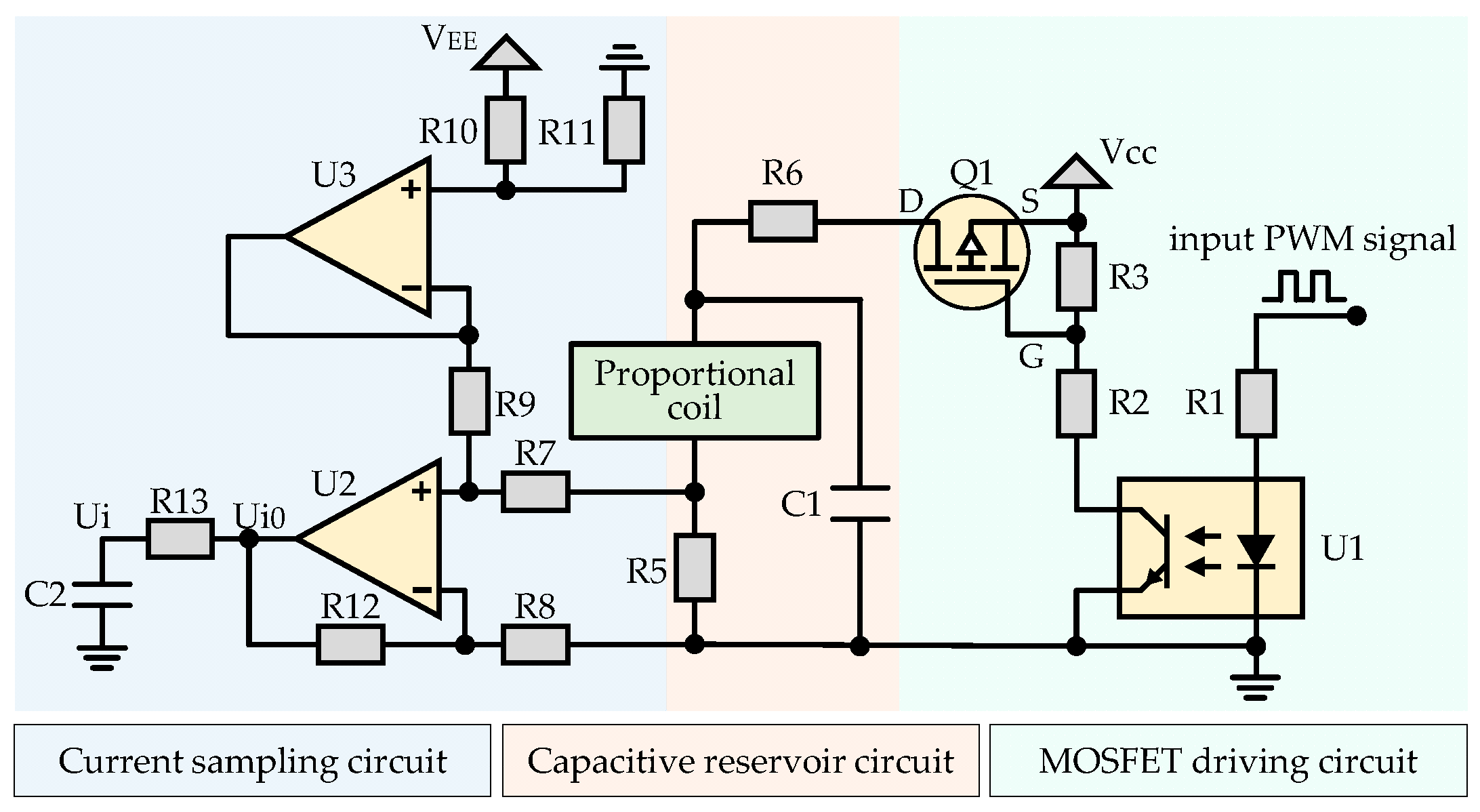
To drive the coil current accurately and rapidly, a CRPDC including a MOSFET driving circuit, a capacitive reservoir circuit, and a current sampling circuit, is developed, as shown in Figure 2. By inputting the PWM voltage signal into the CRPDC, the proportional electromagnet is driven by the resulting coil current. The composition and working principle of the proposed CRPDC are introduced as follows. The MOSFET driving circuit consists of one optocoupler (U1), one P-MOSFET (Q1), and three resistances (R1, R2, and R3). The resistance (R1) is employed to limit the current of the LED side of the optocoupler (U1). While the high-level voltage of the input PWM signal is fed into the LED side of the optocoupler (U1), the detector side of the optocoupler (U1) and the D-S ports of the P-MOSFET (Q1) are in the turn-on state (the voltage difference between the G port and the S port of the P-MOSFET is smaller than −4 V). While the low-level voltage of the input PWM signal is fed into the LED side of the optocoupler (U1), the detector side of the optocoupler (U1) and the D-S ports of the P-MOSFET (Q1) are in the turn-off state (the voltage difference between the G port and the S port of the P-MOSFET is larger than −2 V).
The capacitive reservoir circuit is designed by connecting an energy-storage capacitance to the proportional valve coil in a parallel manner. While the D-S ports of the P-MOSFET (Q1) are in the turn-on state (the control voltage of the G port is below the VCC), the proportional valve coil is directly excited by the power supply (Vcc). Conversely, the proportional valve coil is actuated by the energy-storage capacitance if the P-MOSFET (Q1) is in the turn-off state (the control voltage of the G port is the same as the VCC). The resistance (R5) is applied for current sampling. To limit the charging power of energy-storage capacitance (C1), a power-limiting resistance (R6) is designed.
The current sampling circuit is designed to sense the resulting coil current of the digital driving circuit, which consists of one differential amplifier [28] and one voltage follower [29]. The four resistances (R7, R8, R9, and R12) and one operational amplifier (U2) constitute the differential amplifier. The voltage follower is composed of two resistances (R10, R11) and one operational amplifier (U3), which provides a bias voltage for the differential amplifier to improve the zero-point acquisition accuracy. Moreover, a first-order low-pass filter composed of one resistance (R13) and one capacitance (C2) is designed to reduce the signal noise of the current sampling circuit [30]. The transformed and amplificated coil current can be sensed by measuring the resulting sampling voltage (Ui).

3. Modelling of CRPDC

3.1. Modelling of Capacitive Reservoir Circuit

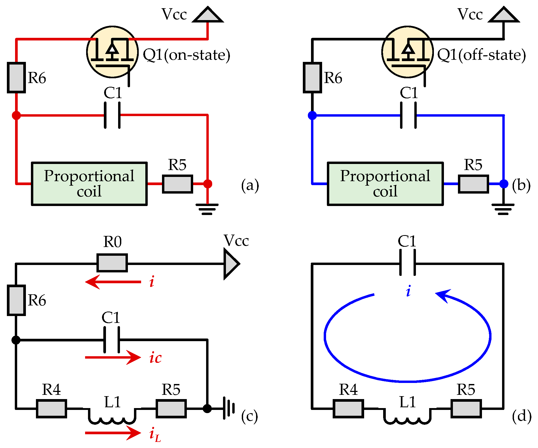
To analyze the resulting coil current of the electro-hydraulic proportional valve driven by the CRPDC, the mathematical models of the charging loop and the discharging loop are established. While the D-S ports of P-MOSFET (Q1) are in the turn-on state, the actual charging circuit and charging equivalent model are shown in Figure 3a,c, respectively. While the D-S ports of P-MOSFET (Q1) are in the turn-off state, the actual discharging circuit and discharging equivalent model are shown in Figure 3b,d, respectively. The resistance (R0) is the static resistance of the P-MOSFET (Q1, while D-S ports are in the turn-on state). As can be seen from the equivalent models in Figure 3c,d, the proportional valve coil is simulated by one inductance (L1) and one resistance (R4).

3.1.1. Charging Modelling of CRPDC

As shown in Figure 3c, the equivalent charging model of the CRPDC consists of the static resistance ( R 0 ) of the P-MOSFET (Q1), the power-limiting resistance ( R 6 ), the equivalent resistance and inductance of proportional valve coil ( R 4 , L 1 ), the energy-storage capacitance ( C 1 ), the current acquisition resistance ( R 5 ), and the power voltage ( V C C ). Based on Kirchhoff’s Current Law (KCL), the current relationship of the equivalent charging circuit can be written as:
i = i C + i L
where i denotes the main current, i C denotes the capacitance current, and i L denotes the inductance current.
The main current i and capacitance current i C can be obtained:
i = V C C L 1 d i L d t i L R 4 + R 5 R 0 + R 6
i C = C 1 L 1 d 2 i L d t 2 + C 1 R 4 + R 5 d i L d t
By substituting the main current Equation (2) and capacitance current Equation (3) into Equation (1), the differential equation for inductance current i L can be formulated as:
C 1 L 1 d 2 i L d t 2 + L 1 R 0 + R 6 + C 1 R 4 + R 5 d i L d t + R 4 + R 5 R 0 + R 6 + 1 i L = V C C R 0 + R 6
With the differential Equation (4), the inductance current i L can be derived as:
i L = K 1 e α 1 t + K 2 e α 2 t + V C C R 0 + R 4 + R 5 + R 6
where
α 1 = 1 2 C 1 ( R 0 + R 6 ) R 4 + R 5 2 L 1 + 1 2 C 1 ( R 0 + R 6 ) + R 4 + R 5 2 L 1 2 R 0 + R 4 + R 5 + R 6 R 0 + R 6 C 1 L 1
α 2 = 1 2 C 1 ( R 0 + R 6 ) R 4 + R 5 2 L 1 1 2 C 1 ( R 0 + R 6 ) + R 4 + R 5 2 L 1 2 R 0 + R 4 + R 5 + R 6 R 0 + R 6 C 1 L 1
The capacitance voltage u C can be expressed as:
u C = L 1 d i L d t + i L R 4 + R 5
By substituting the inductance current Equation (5) into the capacitance voltage Equation (8), the capacitance voltage u C can be rewritten as:
u C = K 1 L 1 α 1 + R 4 + R 5 e α 1 t + K 2 L 1 α 2 + R 4 + R 5 e α 2 t + V C C ( R 4 + R 5 ) R 0 + R 4 + R 5 + R 6
While the initial current i L 0 of inductance L 1 and the initial voltage u C 0 of capacitance C 1 are substituted into the inductance current Equation (5) and capacitance voltage Equation (9), respectively, the coefficients K 1 and K 2 can be derived as:
K 1 = u C 0 ( R 4 + R 5 ) i L 0 L 1 α 2 i L 0 L 1 ( α 1 α 2 ) + α 2 V C C ( α 1 α 2 ) ( R 0 + R 4 + R 5 + R 6 )
K 2 = u C 0 ( R 4 + R 5 ) i L 0 L 1 α 1 i L 0 L 1 ( α 2 α 1 ) + α 1 V C C ( α 2 α 1 ) ( R 0 + R 4 + R 5 + R 6 )
Therefore, while the CRPDC is switched to be in charging circuit mode, the coefficients K 1 and K 2 can be determined by Equations (10) and (11). The following states of inductance current i L (coil current) and capacitance voltage u C can be calculated by Equations (5) and (9), respectively.

3.1.2. Discharging Modelling of CRPDC

The equivalent resistance and inductance of the proportional valve coil ( R 4 , L 1 ), the energy-storage capacitance ( C 1 ), and the current acquisition resistance ( R 5 ) make up the equivalent discharging model of CRPDC, as shown in Figure 3d. Based on Kirchhoff’s Voltage Law (KVL), the voltage relationship of the equivalent discharging circuit can be written as:
u R 4 + u R 5 + u L = u C
where u R 4 is the voltage of resistance ( R 4 ), u R 5 is the voltage of resistance ( R 5 ), u L is the voltage of inductance ( L 1 ), and u C is the voltage of capacitance ( C 1 ).
The main current i can be expressed as:
i = C 1 d u C d t
With the main current in Equation (13), the voltages of resistances ( R 4 , R 5 ) and inductance ( L 1 ) can be derived as:
u R 4 = i R 4 = R 4 C 1 d u C d t
u R 5 = i R 5 = R 5 C 1 d u C d t
u L = L 1 d i d t = L 1 C 1 d 2 u C d t 2
When the voltage Equation (14) of resistance ( R 4 ), voltage Equation (15) of resistance ( R 5 ), and voltage Equation (16) of inductance ( L 1 ) are substituted into Equation (12), the differential equation for capacitance voltage u C can be formulated as:
L 1 C 1 d 2 u C d t 2 + ( R 4 + R 5 ) C 1 d u C d t + u C = 0
Based on Equation (17), the capacitance voltage u C can be deduced as:
u C = A e α t sin ( ω d t + φ )
where
α = R 4 + R 5 2 L 1
ω 0 = 1 L 1 C 1
ω d = ω 0 2 α 2
When the capacitance voltage Equation (18) is substituted into Equation (13), the main current i can be rewritten as:
i = C 1 A e α t α sin ω d t + φ ω d cos ω d t + φ
By substituting the initial voltage u C 0 of capacitance ( C 1 ) and the initial current i L 0 of inductance ( L 1 ) into the capacitance voltage Equation (18) and the inductance current Equation (22), respectively, the phase φ and the coefficient A can be obtained as:
φ = cot 1 ( α ω d i L 0 C 1 u C 0 ω d )
A = u C 0 sin φ
Therefore, while the CRPDC is switched to be in discharging circuit mode, the phase φ and the coefficient A can be determined by Equations (23) and (24), respectively. The following states of capacitance voltage u C and main current i can be calculated by Equations (18) and (22), respectively.

3.2. Modelling of Current Sampling Circuit

As shown in Figure 2, the current sampling circuit is composed of a differential amplifier and a voltage follower. The voltage of acquisition resistance ( R 5 ) is U R 0.1 . The output voltage of the differential amplifier is U i 0 . The bias voltage is U 0.8 . Based on the principle of virtual short and virtual open circuits, the model of the current sampling circuit can be built. For the operational amplifier (U3), the voltages of the input terminal can be expressed as:
U B 0 + = V E E R 11 R 10 + R 11
U B 0 = U 0.8
Based on the principle of virtual short circuit, the following equation can be obtained:
U B 0 + = U B 0
Substituting Equations (25) and (26) into Equation (27), the output voltage of the operational amplifier (U3) can be deduced as:
U 0.8 = V E E R 11 R 10 + R 11
For the operational amplifier (U2), the voltages of the input terminal can be modeled as:
U A 0 + = U 0.8 U R 0.1 R 7 R 7 + R 9 + U R 0.1
U A 0 = U i 0 R 8 R 8 + R 12
Based on the principle of the virtual short circuit, the following equation can be obtained.
U A 0 + = U A 0
By substituting Equations (29) and (30) into Equation (31), the output voltage of the operational amplifier (U2) can be deduced as:
U i 0 = U 0.8 R 7 ( R 8 + R 12 ) R 8 ( R 7 + R 9 ) + U R 0.1 R 9 ( R 8 + R 12 ) R 8 ( R 7 + R 9 )
Substituting Equation (28) into Equation (32), the output voltage of the operational amplifier (U2) can be rewritten as:
U i 0 = V E E R 7 R 11 ( R 8 + R 12 ) R 8 ( R 7 + R 9 ) ( R 10 + R 11 ) + U R 0.1 R 9 ( R 8 + R 12 ) R 8 ( R 7 + R 9 )

4. Simulation Analysis of CRPDC

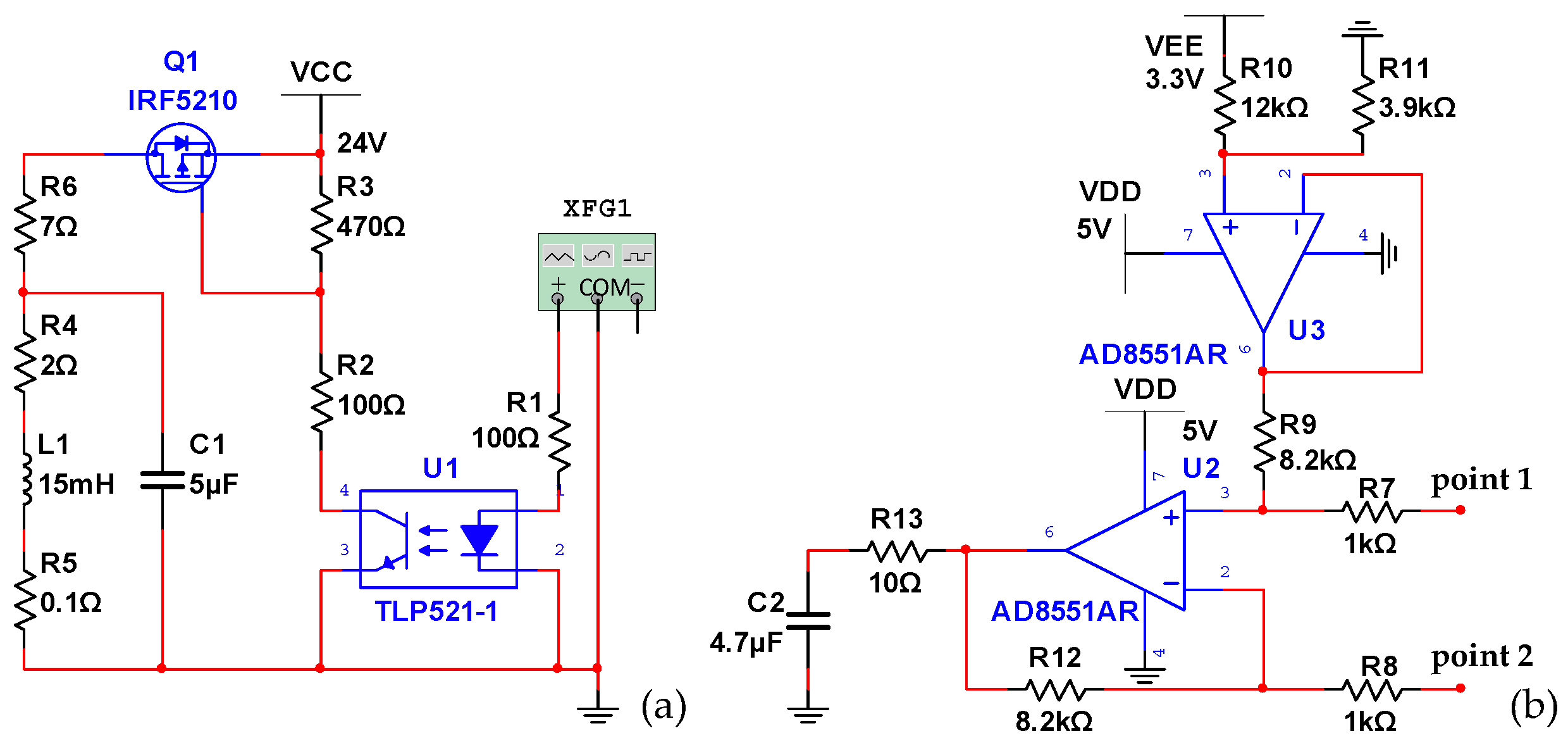
For the proposed CRPDC, the coil current under different PWM frequencies, PWM duty cycles, energy-storage capacitances, and power voltages is calculated and simulated in this section. In addition, the current signal transformation and amplification of CRPDC are calculated and simulated as well. To investigate the PWM driving performance and current-signal transformation performance of the proposed CRPDC, two Multisim models are established, as shown in Figure 4a,b, respectively.

4.1. Coil Currents under Different PWM Frequencies

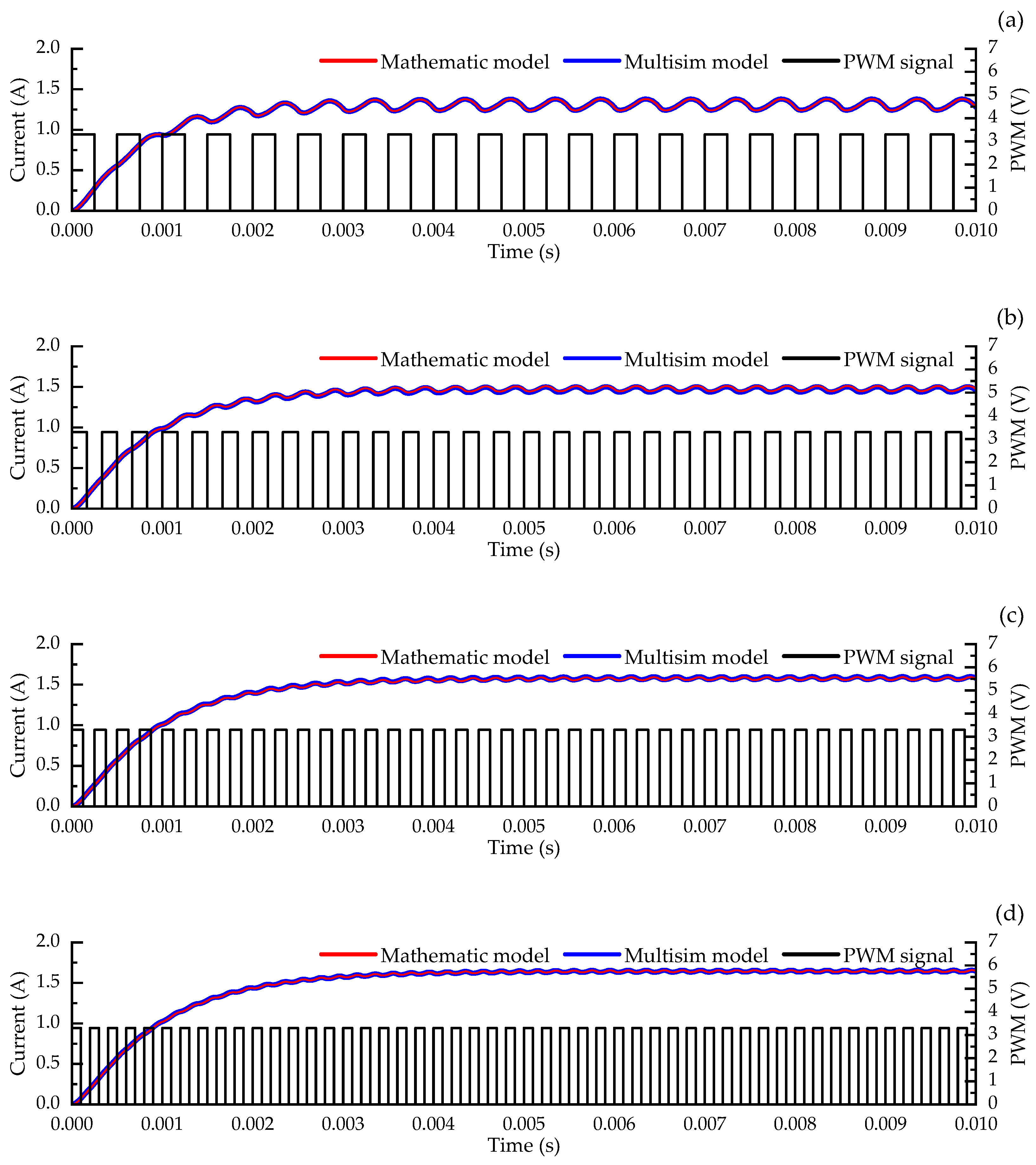
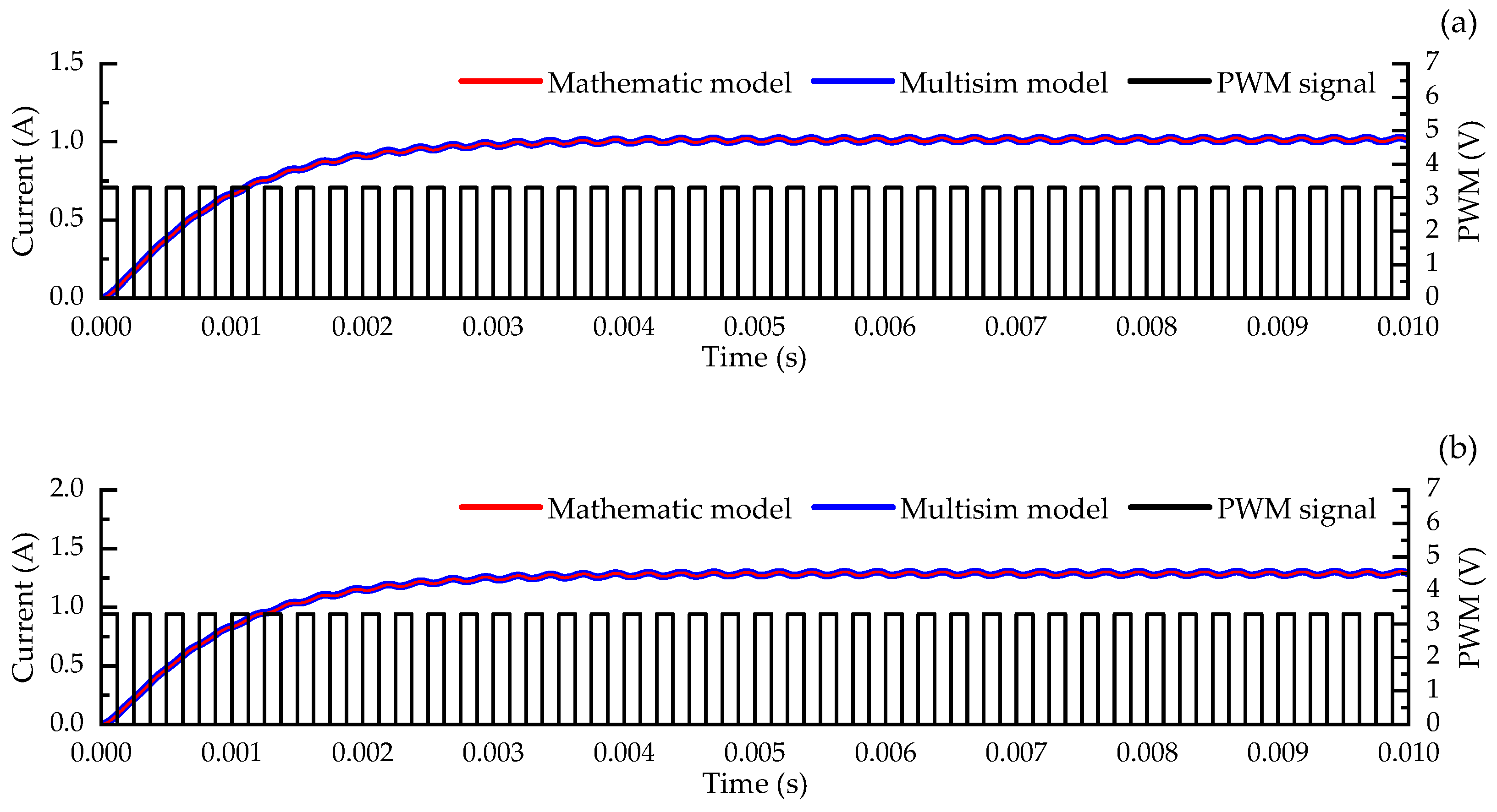
While the input PWM control signals with different frequencies are applied to the proposed CRPDC, the coil current response is simulated and analyzed, as shown in Figure 5. For comparison, the output currents calculated by the mathematical models are shown in Figure 5 as well. The frequencies of input PWM signals are set to be 2.0 kHz, 3.0 kHz, 4.0 kHz, and 5.0 kHz, respectively. The duty cycles of the input PWM signals are all set to be 50%. The duty cycle is defined as the proportion of the high-voltage time to the total time in one cycle. The energy-storage capacitance and the power voltage are configured to be 10 uF and 24 V. As can be seen from Figure 5, the desired coil current can be fulfilled by the CRPDC. The average currents of the proportional valve coil under different PWM frequencies are evaluated to be 1.31 A, 1.48 A, 1.57 A, and 1.64 A (results from the Multisim model), as shown in Figure 6a. The current ripples of the proportional coil under different PWM frequencies are determined to be 140.11 mA, 64.29 mA, 36.25 mA, and 23.10 mA (peak-to-peak values, results from the Multisim model in Figure 4a), as shown in Figure 6b. It is observed that while the frequency of the input PWM signal increases, the output current of the proportional valve coil rises slightly but the current ripple obviously decreases. While the proposed CRPDC works in the turn-on state and turn-off state, the resulting coil current can be described by Equations (5) and (22), respectively. According to Equations (10) and (11), the coefficients K 1 and K 2 of Equation (5) are influenced by the final coil current of the previous turn-off state. From Equations (23) and (24), we found that the phase φ and the coefficient A of Equation (22) are influenced by the final coil current of the previous turn-on state. The switch between the turn-on state and turn-off state will result in a steady-state coil current featured with a ripple. Hence, the average-current and current-ripple values of the resulting coil current are determined by both the circuit parameters and the switching frequency. The current ripple can be regulated by accommodating the input PWM frequency of CRPDC. Moreover, the simulation results are basically consistent with the mathematical calculation results, which confirms the effectiveness of the established mathematical models.

4.2. Coil Currents under Different PWM Duty Cycles

The driving currents of the proportional coil under the different PWM duty cycles are simulated, as shown in Figure 7. The coil currents calculated by the mathematical model are also shown in Figure 7. The frequencies of input PWM signals are all set to be 4 kHz. The duty cycles of the input PWM signals are set to be 20%, 40%, 60%, and 80%, respectively. The energy-storage capacitance and power voltage are configured to be 10 uF and 24 V. As can be seen from Figure 7, the coil current can be adjusted by changing the duty cycle of the input PWM signal. The average currents of the proportional coil at different PWM duty cycles are evaluated to be 0.81 A, 1.33 A, 1.83 A, and 2.33 A (results from the Multisim model in Figure 4a), as shown in Figure 8a. The current ripples of the proportional coil at different PWM duty cycles are determined to be 31.55 mA, 37.42 mA, 33.42 mA, ad 15.28 mA (peak-to-peak values, results from Multisim model), as shown in Figure 8b. As can be seen from the figures, the output average current obviously increases with the increase in the PWM duty cycle. The output current ripple of the proportional coil first increases and then decreases along with the increase in the PWM duty cycle. Therefore, the coil-current amplitude can be regulated by accommodating the duty cycle of the input PWM signal.

4.3. Coil Currents under Different Capacitances

The output current characteristics of the CRPDC with different energy-storage capacitances are further simulated, as shown in Figure 9. The frequencies of the input PWM signals are all set to be 5 kHz. The duty cycles of input PWM signals are all set to be 50%. The energy-storage capacitances are set to be 2 uF, 4 uF, 6 uF, and 8 uF, respectively. The power voltage is configured to be 24 V. The current ripples of proportional valve coil at different energy-storage capacitances are calculated to be 87.80 mA, 53.81 mA, 38.15 mA, and 29.57 mA (peak-to-peak values, results from the Multisim model in Figure 4a). The average currents at different energy-storage capacitances are calculated to be 1.139 A, 1.446 A, 1.564 A, and 1.616 A (results from the Multisim model). As can be seen from Figure 10, with the increase in capacitance, the average current increases slightly but the output current ripple obviously decreases. Hence, the current characteristic of CRPDC can be modulated by choosing the energy-storage capacitance.

4.4. Coil Currents under Different Power Voltage

The influence of power voltage on the coil current is investigated as well, as shown in Figure 11. The frequencies and duty cycles of the input PWM signals are set to be 4 kHz and 50%, respectively. The energy-storage capacitances are all set to be 10 uF. The power voltages are set to be 16 V, 20 V, 24 V, and 28 V, respectively. As can be observed from Figure 11, the resulting average currents at different power voltages are calculated to be 1.014 A, 1.288 A, 1.575 A, and 1.862 A (results from the Multisim model in Figure 4a). The resulting current ripples at different power voltages are determined to be 24.44 mA, 30.41 mA, 36.06 mA, and 42.10 mA (peak-to-peak values, results from the Multisim model). As can be seen from Figure 12, with the increase in the power voltage, the average current and the current ripple of the proportional valve coil both increase in an almost linear way. Hence, the coil-current control characteristics of the proposed CRPDC can be regulated by changing the power voltage. Small power voltage means a small current ripple and low drive capability.

4.5. Current Signal Transformation and Amplification

The current-sampling performance of CRPDC is investigated by simulating the current sampling circuit (based on the mathematic model and the Multisim model in Figure 4b). The input voltages of the current sampling circuit (voltage between point 1 and point 2) are set to be 0 mV, 50 mV, 100 mV, 150 mV, and 200 mV (corresponding to the coil current of 0.0 A, 0.5 A, 1.0 A, 1.5 A, and 2.0 A, considering the current sampling resistance is of 0.1 Ohm), respectively. As shown in Figure 13, the simulation results from the Multisim model (in Figure 4b) agree well with the calculation results of the mathematical model. Both curves (the relationship between the voltage of the sampling resistance and the output voltage of the differential amplifier) display linear characteristics. Therefore, the current sampling circuit is able to accurately transform and amplify the coil current.

5. Comparison of CRPDC with Other Driving Circuit

Finally, a characteristic comparison is carried out between the proposed CRPDC and one traditional driving circuit. Figure 14a depicts the schematic diagram of the traditional reverse discharging power driving circuit (RDPDC), which is made up of one optocoupler, two MOSFET components, and two diodes [19,31,32,33]. For the RDPDC, while the voltage of the input PWM signal is at a high level, the proportional valve coil is driven by the Vcc power source directly. While the voltage of the input PWM signal is at a low level, the holding current of the proportional valve coil will flow through the two diodes and back to the Vcc power source [34].
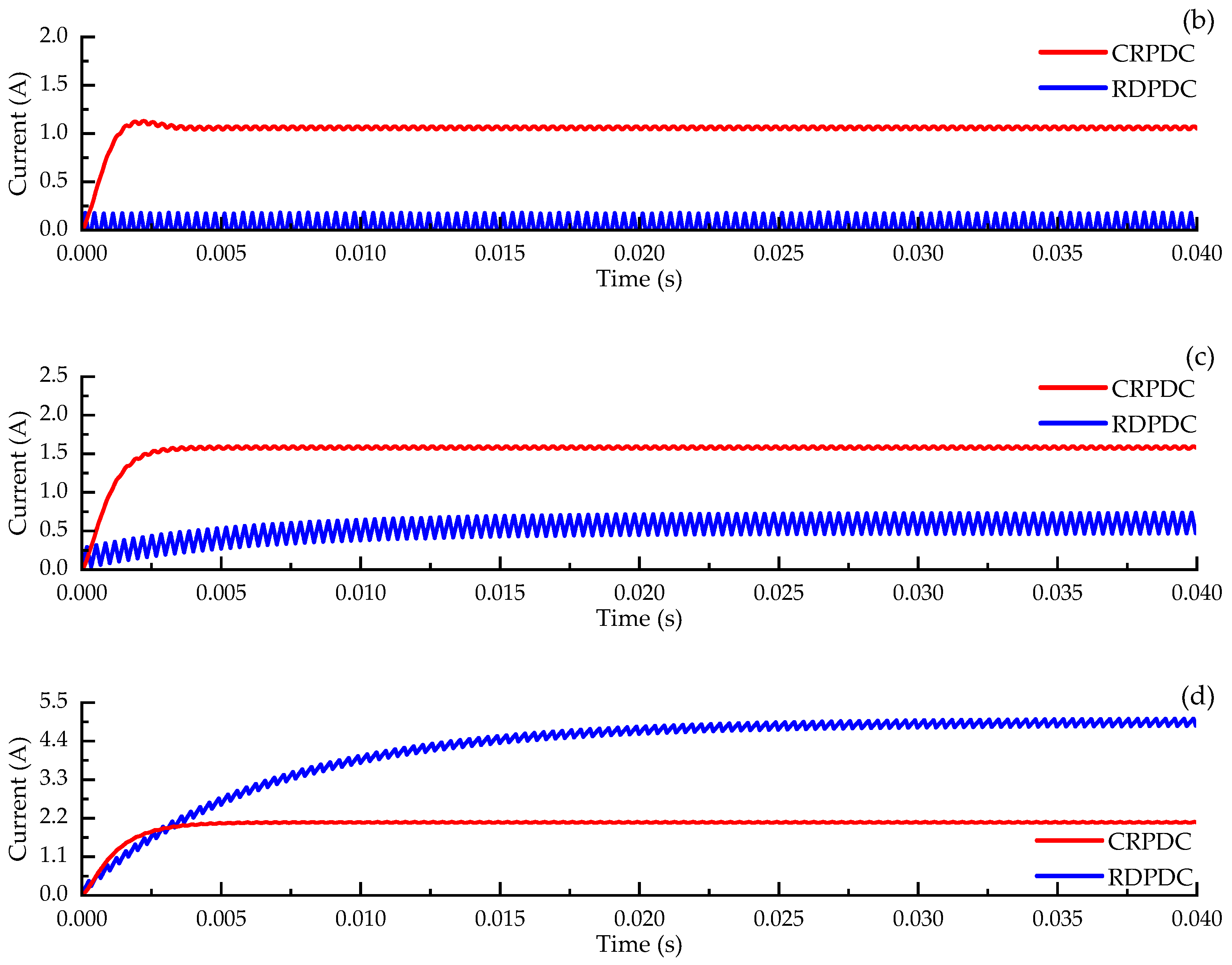
The characteristics of traditional RDPDC are simulated on the NI Multisim 14.0 software as well, as shown in Figure 14b. While 3 kHz PWM signals (Vcc: 24 V) with various duty cycles are used to drive the proposed CRPDC (energy-storage capacitance value: 20 uF) and the traditional RDPDC, the results are depicted in Figure 15. It is found that the rise time (from 10% to 90% steady-state value) of the traditional RDPDC under the 70% duty cycle is 12.90 ms. In contrast, the rise time of CRPDC under the 70% duty cycle is evaluated to be 2.58 ms, which means a faster and more stable dynamic response. For the traditional RDPDC, the steady-state error defined as the maximum deviation value from the average value of coil current (from 0.03 s to 0.04 s) is calculated as 45.3 mA, 98.6 mA, 141.0 mA, and 133.2 mA, respectively. In contrast, the steady-state error of the proposed CRPDC is evaluated to be 9.7 mA, 15.8 mA, 16.7 mA, and 12.0 mA, which means a high-accuracy current-control capability. The traditional RDPDC results in a large discharging speed of coil current, which further contributes to a poor steady-state current. In contrast, the coil current response of the proposed CRPDC is stable and fast. Therefore, the proposed CRPDC can realize the coil current with high accuracy and a fast response.

6. Conclusions

The main contribution of the present work is the design, modeling, and characteristic analysis of the new CRPDC. The effects of the duty cycle, pulse frequency, energy-storage capacitance, and power voltage on the output current are investigated by a mathematical model and a simulation model. The current control performance of the proposed CRPDC is compared to the traditional RDPDC. Five main conclusions can be drawn as follows:
(1)
By adding an energy-storage capacitance to the proportional valve coil in a parallel manner, the designed CRPDC is able to drive the coil current with high accuracy and a fast response.
(2)
The current ripple of the CRPDC can be regulated by modulating the frequency of the PWM signal. While the frequencies are set to be 2 kHz, 3 kHz, 4 kHz, and 5 kHz, the resulting current ripples are 140.11 mA, 64.29 mA, 36.25 mA, and 23.10 mA.
(3)
The current amplitude of the CRPDC can be adjusted by changing the duty cycle of the PWM signal. While the duty cycles are set to be 20%, 40%, 60%, and 80%, the resulting coil currents are 0.81 A, 1.33 A, 1.83 A, and 2.32 A.
(4)
The coil current control characteristic of the CRPDC can also be improved by choosing the appropriate energy-storage capacitance and power voltage.
(5)
Future research efforts will be focused on studying the influence of other parameters on the coil current such as the inlet pressure, comparing the simulation results and the experimental results, and controlling the proposed CRPDC by closed-loop control algorithms [35,36].

Author Contributions

Conceptualization, X.L., X.Y. and S.L.; methodology, X.L. and X.Y.; validation, X.L. and X.Y.; writing, X.L., X.Y. and D.L. All authors have read and agreed to the published version of the manuscript.

Funding

This research was funded by the National Key R&D Program of China under Grant 2019YFB2005303, the Jiangsu Province Marine Science and Technology Innovation Project under Grant JSZRHYKJ202215, and the National Natural Science Foundation of China under Grant 52175018.

Institutional Review Board Statement

Not applicable.

Informed Consent Statement

Not applicable.

Data Availability Statement

Not applicable.

Conflicts of Interest

The authors declare no conflict of interest.

References

  1. Huova, M.; Tammisto, J.; Linjama, M.; Tervonen, J. Fuel efficiency analysis of selected hydraulic hybrids in a wheel loader application. In Proceedings of the BATH/ASME 2018 Symposium on Fluid Power and Motion Control, Bath, UK, 12–14 September 2018; pp. 1–10. [Google Scholar]
  2. Richard, S.; Kurt, S. Modelling and Control of a Hydraulic Actuated Large Scale Manipulator. Proc. Appl. Math. Mech. 2004, 4, 141–142. [Google Scholar]
  3. Zagar, P.; Scheidl, R. A Piezo-Electric Valve Actuator for Hydraulic Exoskeleton Drives. Int. J. Fluid Power 2022, 23, 453–468. [Google Scholar]
  4. Rituraj, R.; Scheidl, R.; Ladner, P.; Lauber, M.; Plöckinger, A. Prototyping and Experimental Investigation of Digital Hydraulically Driven Knee Exoskeleton. Energies 2022, 15, 8695. [Google Scholar] [CrossRef]
  5. He, Q.H.; Hao, P.; Zhang, D.Q. Modeling and parameter estimation for hydraulic system of excavator’s arm. J. Cent. South Univ. Technol. 2008, 15, 382–386. [Google Scholar] [CrossRef]
  6. Cheng, M.; Li, L.; Ding, R.; Xu, B. Real-Time Anti-Saturation Flow Optimization Algorithm of the Redundant Hydraulic Manipulator. Actuators 2021, 10, 11. [Google Scholar] [CrossRef]
  7. Zhai, F.G.; He, Z.Q.; Zhao, Y.F.; Yang, Y.; Kong, X.D. Control methodology of synchronous lifting for the dual forging manipulator at clamping condition. Sci. Rep. 2022, 12, 3920. [Google Scholar] [CrossRef]
  8. Tong, Z.M.; Wu, S.S.; Tong, S.G.; Yue, Y.Q.; Li, Y.S. Energy-saving technologies for construction machinery: Review of electro-hydraulic pump-valve coordinated system. J. Zhejiang Univ. Sci. A (Appl. Phys. Eng.) 2020, 21, 331–349. [Google Scholar] [CrossRef]
  9. Liu, T.; Gong, G.F.; Yang, H.Y.; Cheng, Y.L.; Chen, Y.X.; Zhou, X.H. A novel cutterhead off-stuck strategy for tunnel boring machine based on electro-hydraulic hybrid driving. Adv. Mech. Eng. 2019, 11, 1687814019895929. [Google Scholar] [CrossRef] [Green Version]
  10. Yun, S.N.; Lee, Y.L.; Khan, H.A.; Kang, C.N.; Ham, Y.B.; Park, J.H. Proportional Flow Control Valve for Construction Vehicle. In Proceedings of the 2019 23rd International Conference on Mechatronics Technology (ICMT), Salerno, Italy, 23–26 October 2019; pp. 1–3. [Google Scholar]
  11. Ding, R.Q.; Xu, B.; Zhang, J.H.; Cheng, M. Bumpless mode switch of independent metering fluid power system for mobile machinery. Autom. Constr. 2016, 68, 52–64. [Google Scholar] [CrossRef]
  12. Chen, C.P.; Chiang, M.H. Development of Proportional Pressure Control Valve for Hydraulic Braking Actuator of Automobile ABS. Appl. Sci. 2018, 8, 639. [Google Scholar] [CrossRef] [Green Version]
  13. Liu, J.R.; Bo, J.; Xie, Y.J.; Chen, Y.; Weng, Z.T. Investigation on the characteristics of a new high frequency three-way proportional pressure reducing valve in variable valve system of automobile engine. Indian J. Eng. Mater. Sci. 2009, 16, 7–13. [Google Scholar] [CrossRef]
  14. Renn, J.C.; Tsai, C. Development of an unconventional electro-hydraulic proportional valve with fuzzy-logic controller for hydraulic presses. Int. J. Adv. Manuf. Technol. 2005, 26, 10–16. [Google Scholar] [CrossRef]
  15. Xu, B.; Shen, J.; Liu, S.H.; Su, Q.; Zhang, J.H. Research and Development of Electro-hydraulic Control Valves Oriented to Industry 4.0: A Review. Chin. J. Mech. Eng. 2020, 33, 29. [Google Scholar] [CrossRef] [Green Version]
  16. Bose, C. The Advantages of New Proportional and Servo Valves with Integrated Digital Electronics; Technical Paper; Moog: Trumansburg, NY, USA, 2003. [Google Scholar]
  17. Ibrahim, E.E.; Elnady, T.; Hassan, M.S.; Saleh, I. Electro-Hydraulic Proportional System Real Time Tracking Control Development Based on Pulse width Modulation Method. Commun. Sci. Lett. Univ. Zilina 2021, 23, B336–B345. [Google Scholar]
  18. Lu, Q.S.; Bao, H.; Li, J. Research on Embedded Electro-hydraulic Proportional Valve Controller. In Proceedings of the 2009 Third International Symposium on Intelligent Information Technology Application, Nanchang, China, 21–22 November 2009; pp. 91–94. [Google Scholar]
  19. Nie, Y.; Wang, Q.F. Tri-state Modulation Power Driving of Electro-hydraulic Proportional Amplifier. Chin. J. Mech. Eng. 2009, 22, 639–644. [Google Scholar] [CrossRef]
  20. Zhang, J.H.; Lu, Z.Y.; Xu, B.; Wang, D.; Pan, M. Investigation Into the Nonlinear Characteristics of a High-Speed Drive Circuit for a Proportional Solenoid Controlled by a PWM Signal. IEEE Access 2018, 6, 61665–61676. [Google Scholar] [CrossRef]
  21. Shen, W.; Wang, J.Z. A Driving Method of the Electro Hydraulic Proportional Valve Based on Compensation Network. In Informatics in Control, Automation and Robotics; Springer: Berlin/Heidelberg, Germany, 2011; pp. 199–204. [Google Scholar]
  22. Kang, J.; Shang, S.S.; Jiao, W.X.; Wang, X.; Pu, D.C.; Niu, Z.; Ye, Q.T.; Wang, C.H. Proportional Electromagnetic Valve Driven by Frequency-varying PWM. Chin. J. Mech. Eng. 2015, 26, 1024–1028. [Google Scholar]
  23. Liu, Z.Z.; Zhang, Z.X.; Hou, Y.J. Double-voltage Control Mode of Electro-pneumatic Proportional Pressure Valve with High Voltage Driving and Low Voltage PWM. Trans. Chin. Soc. Agric. Mach. 2008, 39, 159–163. [Google Scholar]
  24. Digital Proportional Relief Valves. Available online: https://www.atos.com/tables/english/FS010.pdf (accessed on 24 July 2023).
  25. Wang, D.; Zhang, S.Z.; Wang, L.P.; Liu, Y.M. Developing a Ball Screw Drive System of High-Speed Machine Tool Considering Dynamics. IEEE Trans. Ind. Electron. 2022, 69, 4966–4976. [Google Scholar] [CrossRef]
  26. Yang, X.; Liu, H.T.; Xiao, J.L.; Zhu, W.L.; Liu, Q.; Gong, G.F.; Huang, T. Continuous Friction Feedforward Sliding Mode Controller for a TriMule Hybrid Robot. IEEE/ASME Trans. Mechatron. 2018, 23, 1673–1683. [Google Scholar] [CrossRef]
  27. Eryilmaz, B.; Wilson, B.H. Unified modeling and analysis of a proportional valve. J. Frankl. Inst. 2006, 343, 48–68. [Google Scholar] [CrossRef]
  28. Pallas-Areny, R.; Webster, J.G. Common Mode Rejection Ratio in Differential Amplifiers. IEEE Trans. Instrum. Meas. 1991, 40, 669–676. [Google Scholar] [CrossRef]
  29. Sankaran, P.; Kanagasabapathy, P. Use of a voltage follower for the error reduction of a voltage transformer. IEE Proc. 1978, 125, 1272–1273. [Google Scholar] [CrossRef]
  30. Byun, S. Closed-Form Equation of Data Dependent Jitter in First Order Low Pass System. Sci. World J. 2014, 2014, 694178. [Google Scholar] [CrossRef] [PubMed] [Green Version]
  31. Liu, X.H.; Lu, Y.X. Research on Proportional Amplifer. Chin. Hydraul. Pneum. 1989, 2, 26–29. [Google Scholar]
  32. Xu, B.; Su, Q.; Zhang, J.H.; Lu, Z.Y. Analysis for drive circuit and improved current controller for proportional amplifier. J. Zhejiang Univ. (Eng. Sci.) 2017, 51, 800–806. [Google Scholar]
  33. Qiang, Y.; Zhao, C.L.; Wei, L.J.; Wang, Y.Q.; Li, W.; Luo, X.M. An Analog-Digital Hybrid Proportional Control Amplifier Based on MC9S12XS128. Meas. Control. Technol. 2021, 40, 78–82. [Google Scholar]
  34. Liu, G.P.; Xia, W.X.; Qi, D.W.; Hu, R.H. Analysis of Dither in PWM Control on Electro-hydraulic Proportional Valve. Telkomnika Indones. J. Electr. Eng. 2013, 11, 6808–6814. [Google Scholar] [CrossRef]
  35. Caponetto, R.; Fortuna, L.; Porto, D. Parameter tuning of a non-integer order PID controller. In Proceedings of the Fifteenth International Symposium on Mathematical Theory of Networks and Systems, Notre Dame, IN, USA, 12–16 August 2002; pp. 2332–2338. [Google Scholar]
  36. Bucolo, M.; Buscarino, A.; Famoso, C.; Fortuna, L.; Frasca, M. Control of imperfect dynamical systems. Nonlinear Dyn. 2019, 98, 2989–2999. [Google Scholar] [CrossRef]
Figure 1. The proportional relief valve.
Applsci 13 08825 g001
Figure 2. Circuit design of CRPDC.
Applsci 13 08825 g002
Figure 3. Charging and discharging work modes of the CRPDC: (a) Actual charging circuit; (b) actual discharging circuit; (c) charging equivalent model; (d) discharging equivalent model.
Applsci 13 08825 g003
Figure 4. Multisim model of CRPDC: (a) Capacitive reservoir circuit; (b) current sampling circuit.
Applsci 13 08825 g004
Figure 5. The resulting coil currents of CRPDC under different PWM frequencies: (a) 2 kHz; (b) 3 kHz; (c) 4 kHz; (d) 5 kHz.
Applsci 13 08825 g005
Figure 6. The current characteristics of CRPDC under different PWM frequencies (results from Multisim model): (a) Average current; (b) current ripple (peak-to-peak value).
Applsci 13 08825 g006
Figure 7. The coil currents of CRPDC under different PWM duty cycles: (a) 20% duty cycle; (b) 40% duty cycle; (c) 60% duty cycle; (d) 80% duty cycle.
Applsci 13 08825 g007
Figure 8. The current characteristics of the CRPDC under the different PWM duty cycles (results from Multisim model): (a) Average current; (b) current ripple (peak-to-peak value).
Applsci 13 08825 g008
Figure 9. The resulting coil currents of CRPDC under different energy-storage capacitances: (a) 2 uF; (b) 4 uF; (c) 6 uF; (d) 8 uF.
Applsci 13 08825 g009aApplsci 13 08825 g009b
Figure 10. The current characteristics of the CRPDC under the different energy-storage capacitances (results from Multisim model): (a) Average current; (b) current ripple (peak-to-peak value).
Applsci 13 08825 g010
Figure 11. The resulting coil currents of CRPDC under different driving voltages: (a) 16 V; (b) 20 V; (c) 24 V; (d) 28 V.
Applsci 13 08825 g011aApplsci 13 08825 g011b
Figure 12. The current characteristics of the CRPDC under different driving voltages (results from Multisim model): (a) Average current; (b) current ripple (peak-to-peak value).
Applsci 13 08825 g012
Figure 13. Relationship between the voltage of sampling resistance and the output voltage of current sampling circuit.
Applsci 13 08825 g013
Figure 14. The traditional RDPDC: (a) Schematic diagram; (b) Multisim model.
Applsci 13 08825 g014
Figure 15. The coil currents of proposed CRPDC and traditional RDPDC under different duty cycles: (a) 10%; (b) 30%; (c) 50%; (d) 70%.
Applsci 13 08825 g015aApplsci 13 08825 g015b
Disclaimer/Publisher’s Note: The statements, opinions and data contained in all publications are solely those of the individual author(s) and contributor(s) and not of MDPI and/or the editor(s). MDPI and/or the editor(s) disclaim responsibility for any injury to people or property resulting from any ideas, methods, instructions or products referred to in the content.