Article

Numerical Simulation and Field Test of a PDC Bit with Mixed Cutter Arrangement to Break Non-Homogeneous Granite

College of Mechanical Engineering, Xi’an Shiyou University, Xi’an 710065, China
*
Authors to whom correspondence should be addressed.
Appl. Sci. 2023, 13(16), 9133; https://doi.org/10.3390/app13169133
Submission received: 12 July 2023 / Revised: 7 August 2023 / Accepted: 9 August 2023 / Published: 10 August 2023

Abstract

:
As the depth of petroleum drilling increases, the strata environment becomes more complex. The efficiency and lifespan of Polycrystalline Diamond Compact (PDC) drill bits fail to meet current drilling demands. However, the structure and arrangement of PDC cutters are valuable determinants of drilling efficiency, although related research still has gaps and deficiencies. This study focuses on PDC cutters in axe, triangular prism, and circular forms. It establishes an inhomogeneous granite model based on the actual measurements of granite and verifies the accuracy of this model through uniaxial compression simulation. Finite element models of three types of cutters in various combination schemes are constructed to examine rock-breaking effects, with the best scheme optimized using Box-Behnken response surface methodology. The rock-breaking process of the optimal PDC drill bit layout has been compared to that of a single cutter bit. Field drilling has demonstrated the effectiveness of a mixed cutter arrangement. The results show that the inhomogeneous granite model can be trusted. The optimal arrangement involves axe cutters in the front row and an alternate arrangement of triangular prism cutters and axe cutters in the back row. The optimal lateral and longitudinal distances for the triangular cutters from the front row of axe cutters are 10 mm and 7 mm, respectively, while those for the back row of axe cutters from the front row are 10.06 mm and 7 mm, respectively. The ROP standard deviation in the drilling process of mixed cutter bits decreases by 53.06% and 43.08% compared to axe and triangular prism cutter bits, respectively. The drilling efficiency increases by 16.8% and 16.6%, respectively, demonstrating higher efficiency and stability. Field drilling results indicate that a mixed cutter bit increases efficiency by 23.5% compared to a bit with only triangular prism cutters. This study posits that research on the combination schemes and parameters of PDC cutters can significantly enhance drilling efficiency, thereby reducing the drilling cycle and costs.

1. Introduction

China has successfully tapped its domestic shallow oil and gas reservoirs and is now shifting its focus toward the development of unconventional oil and gas resources, which will be the primary area of exploration and production in the future. According to a comprehensive survey and study, China holds the second-largest reserves of unconventional oil and gas resources globally. However, the country’s heavy reliance on external sources for oil and natural gas stands at approximately 73% and 43%, respectively. Therefore, there is an urgent need to intensify the exploration and exploitation of unconventional oil and gas resources [1]. However, unconventional oil and gas resources are located in complex formations and are difficult to extract [2], which puts higher requirements on the performance of drill bits. It is well known that PDC (Polycrystalline Diamond Compact) bits have higher wear resistance and efficiency compared with roller cone bits, especially in hard formations [3,4], leading to a higher market share of PDC bits, which was investigated to be as high as 75–80% in 2018 [5,6]. Nevertheless, the prevailing PDC bits utilized in drilling operations predominantly rely on the shearing action provided by the mounted cutters. This shearing action, however, exhibits limited aggressiveness, making it challenging to penetrate hard rocks such as granite. As a result, PDC cutters are required to repeatedly rub against the rock surface and await the accumulation of sufficient energy from the drill string to effectively break the rock. Consequently, this approach significantly diminishes the drill bit’s lifespan and efficiency, escalating drilling costs. Therefore, there is a pressing need to enhance the performance of PDC bits, with the structure of the PDC cutter playing a crucial role in determining their overall performance.
Investigating and optimizing the performance of PDC cutters with diverse structures is a proven approach to enhancing drill bits’ overall lifespan and efficiency [7]. As a result, numerous researchers have devoted significant efforts to exploring the rock-breaking characteristics of PDC cutters with various structures and assessing their suitability for specific formations, with particular emphasis on non-planar cutters [8]. Dong et al. [9] conducted a study on the rock-breaking characteristics and efficiency of circular cutters, axe-shaped cutters, angled cutters, wedge-shaped cutters, and triangular prism cutters through experiments combined with numerical simulation methods. Their results showed that the axe cutters have better drilling ability in hard formations and are suitable for the front row of the cutter blade of the PDC bit, while the angled cutters are more suitable for auxiliary rock breaking and should be installed in the back row of the cutter blade of the PDC bit. Conical PDC cutters are mostly used for auxiliary rock breaking in PDC bits [10,11]. Li et al. [12] used the finite element method to numerically simulate the rock-breaking process of conventional PDC cutters, conical PDC cutters, and the overall rock-breaking process of the drill bit, and the results of the study showed that the conical cutters as auxiliary cutting structures could well produce pre-breaking of rocks at 100 MPa compressive strength, thus improving the overall drilling ability of the bit in hard rocks, while this approach was not effective for rocks with 50 MPa compressive strength. The axe PDC cutter not only has the characteristics of a conventional cutter’s shear breaking in the rock-breaking process but also has a crushing effect on the rock, which can significantly improve the ROP and mechanical specific energy (MSE) of the drill bit [13,14]. The distinctive ridged structure of the axe PDC cutter not only reduces the weight of the drill bit but also optimizes rock-breaking efficiency. Research has shown that a drill bit equipped with an axe cutter can achieve an instantaneous rate of penetration (ROP) that is up to 35% higher compared to the same input energy applied with other cutter designs [15].
The axe PDC cutter demonstrates a high rate of penetration (ROP) in rock breaking, facilitating easier penetration of hard rocks. This, in turn, helps prevent bit sticking and sliding [16], maintains stable weight on the bit (WOB) during drilling, and enables the bit to maintain a high ROP. Additionally, its simple structure, ease of processing, and relatively mature technology make it an advantageous choice for drilling into hard rock formations.
In addition to axe-shaped cutters, new cutter structures have been proposed by some scholars and verified by experiments or numerical simulations. For example, Wang et al. [17] designed a wavy PDC cutter using the mole paw toe as a bionic prototype, and it was found by field experiments that the life and efficiency of PDC bits could be improved by 54% and 230%, respectively, using this cutter, which provided new ideas and methods for the performance improvement of PDC bits. Zeng et al. [18] designed a triangular non-planar PDC cutter, numerically simulated its rock-breaking process, and compared it with conventional PDC cutters. They found that the designed cutter was subject to less rock-breaking resistance, was easier to break the rock, and had both good wear resistance and efficiency. Liu et al. [19] studied the rock-breaking characteristics of the triangular prism PDC cutter by numerical simulation and found that this cutter not only has a shearing effect on the rock but also has a crushing effect. The results of field experiments showed that the PDC bit using this cutter requires less torque and penetrates the rock more easily, which helps the bit’s stability. The change or optimization of the cutter structure is a more intuitive way to improve the performance of the bit. In addition, the reasonable arrangement of the cutter position on the PDC bit blade can also improve the performance of the drill bit to a great extent.
To rationalize the cutter layout, Chen et al. [20] changed the cutter layout by extracting the characteristic curve of the Siberian sheep’s horn, which will be applied to the design of the cutter blade of the PDC drill bit. After the study, the probability of load concentration with the changed cutter was greatly reduced, the utilization rate of the cutter was increased to 90%, and the overall life and efficiency of the PDC drill bit were improved. Previous PDC cutters were often arranged in one row on the cutter blade [21], which would lead to wasted space on the cutter blade. Gradually, the cutter layout of some drill bits began to be changed to two or even more rows on one cutter blade [22], which not only rationalized the use of space on the cutter blade but also improved the efficiency and lifetime of PDC drill bits. Even if the cutter structure is not changed, changing the cutter space arrangement can greatly improve the performance of the whole drill bit [12], and these studies mentioned above provide theoretical support for the cutter space layout.
A systematic approach is crucial in the investigation of the rock-breaking process associated with PDC bits. Most of the current related studies, using experiments combined with numerical simulations [23], have greatly improved the accuracy of the simulations while reducing the research cost. However, most of the studies treat the rock as a homogeneous model during the numerical simulation, which does not reflect the real scenario of the actual drilling process. In addition, the current studies on PDC cutting tool-related parameters, such as back rake angle [24], depth of cut [25], and speed [26], are conducted in an interval-modified parameter study, which yields experimental results that do not necessarily reflect the true relationship between the parameters and the target variables and thus may lead to inaccurate conclusions.
Box-Behnken is a method for constructing multi-factor orthogonal rotating combination experiments [27], which considers the random error in the experimental process and allows for continuous analysis of each level in the process of finding the optimal test conditions. The method can fit unknown complex functional relationships with simple primary or quadratic polynomials in a small area, which is computationally simple and can solve practical problems. The above method simplifies the optimization process and, at the same time, can obtain more reliable results [28], which provides ideas and ways to solve optimization problems in engineering.
It is evident from the aforementioned studies that although the performance of axe and triangular prism cutters has been extensively validated, most of the related research has focused on the rock-breaking characteristics of individual cutters. However, the mixed layout of cutters has the potential to effectively enhance the rock-breaking performance of drill bits, yet there is limited research in this area, particularly regarding the mixed arrangement schemes and relevant parameters. Furthermore, the current research suffers from the limitation that numerical simulations cannot accurately reflect the conditions of real formations. In this study, based on the field-measured data for granite, a heterogeneous granite model was constructed using Python scripts in the ABAQUS 2021 software. Employing the principles of elastoplastic mechanics and rock mechanics, with Drucker-Prager as the rock-yielding criterion, finite element models of different combinations of axe, triangular prism, and cylindrical PDC cutters were developed to simulate the rock-breaking process. A comparison of the rock-breaking processes for different schemes was conducted to determine the optimal cutter combination scheme. The Box-Behnken response surface method was utilized to optimize the cutter spacing of the optimal cutter combination scheme. Based on the obtained parameters, a mixed-arrangement PDC drill bit was constructed and numerically simulated for rock-breaking, with a comparison to a single-row toothed drill bit. Field experiments were conducted to validate the results of the numerical simulation study. The research findings have significant implications for rational cutter arrangement and the enhancement of PDC drill bit performance.

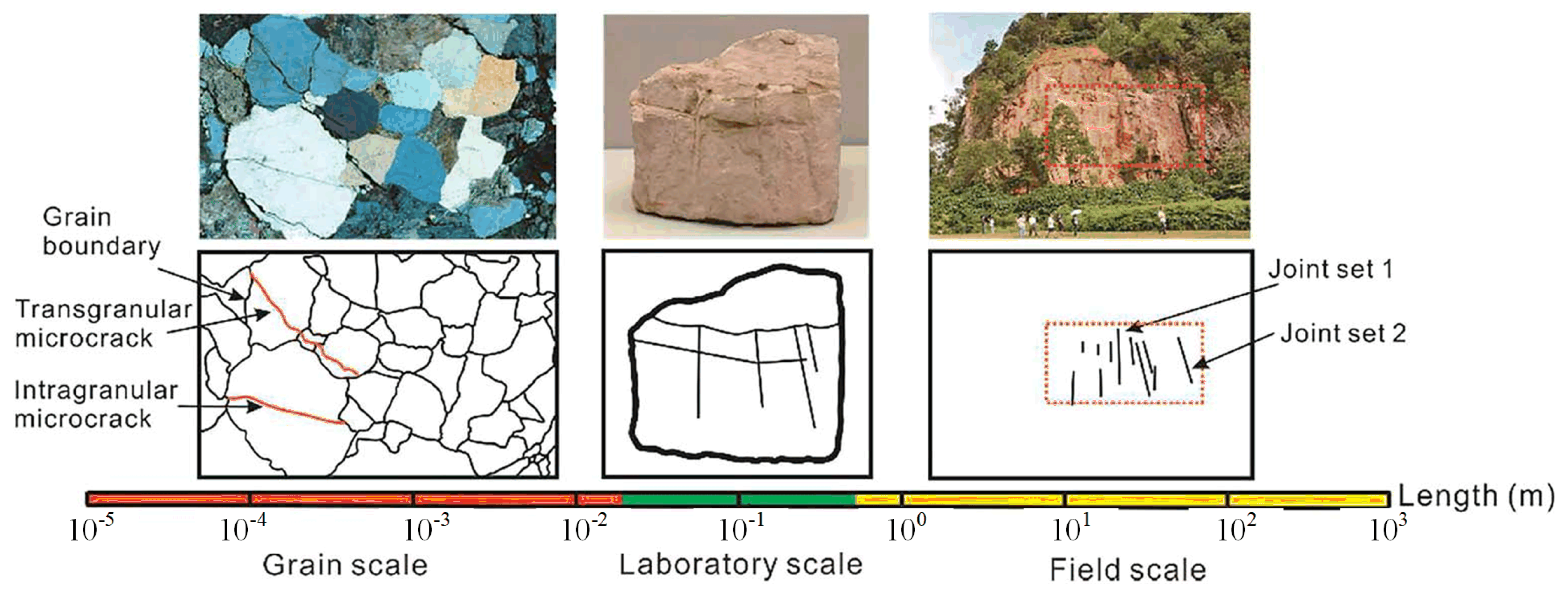
2. Modeling and Validation of Non-Homogeneous Granites

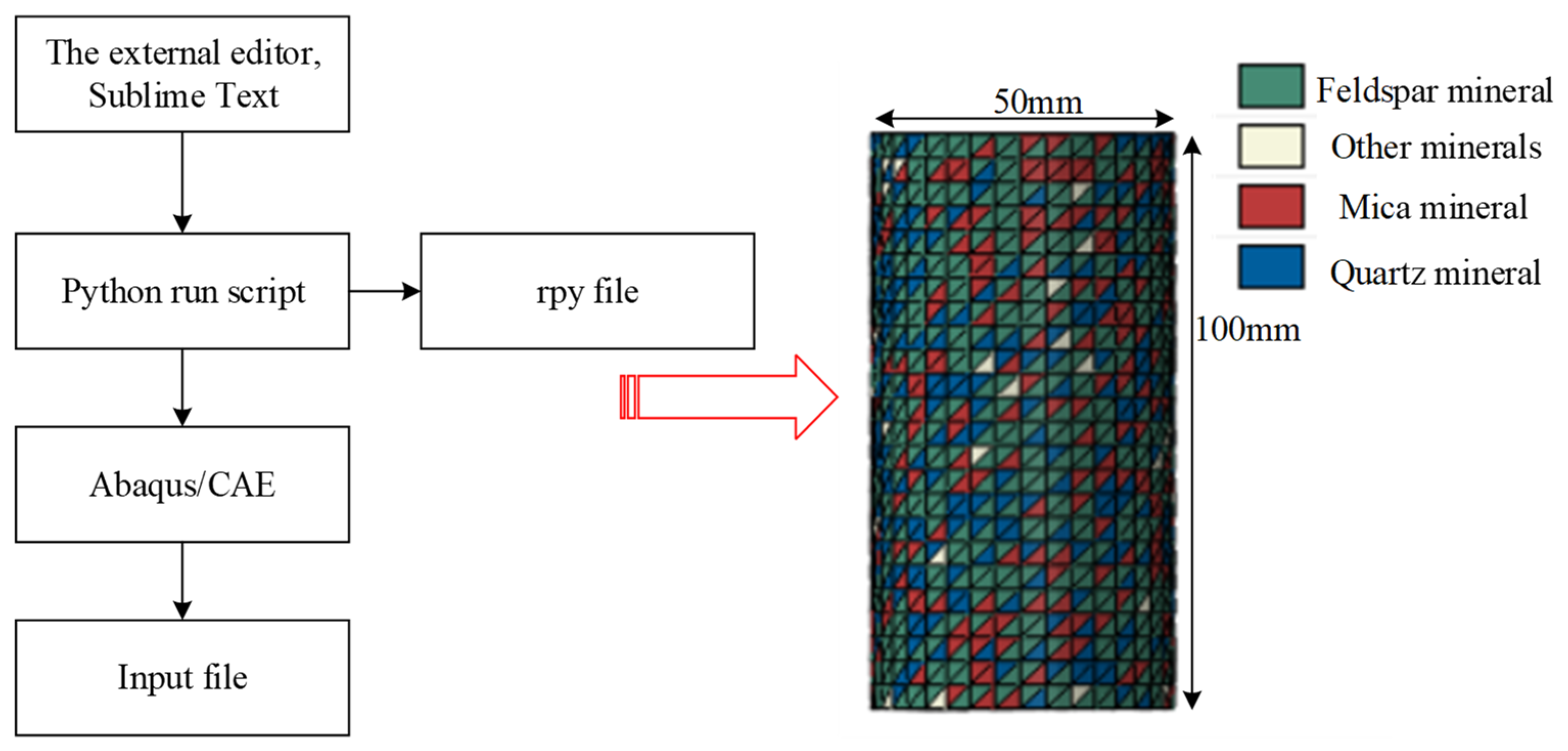
2.1. Modeling of Non-Homogeneous Granites

As shown in Figure 1, microscopic observations were made by examining the actual granite samples. As can be seen from the figure, the actual granite is not homogeneous and contains many different mineral crystals. All of these crystal structures have distinctive dimensional and mechanical characteristics and vary widely and differently [29].
To reflect the condition of the granite formation during actual drilling, the material properties of each component crystal in the granite, based on the actual measurements obtained in the literature [30,31], are shown in Table 1.
By utilizing the parameters outlined in Table 1, the external compiler, Sublime Text, was employed to develop Python scripts. These Python scripts were then saved in the rpy file format and subsequently imported into the ABAQUS CAE module. Firstly, the material properties of each mineral component were generated based on the scripts, followed by the formation of the respective mineral sets. The sets and materials were then correlated with the finite element mesh model through the generation of random numbers. Ultimately, the rock model, shown in Figure 2, was obtained.

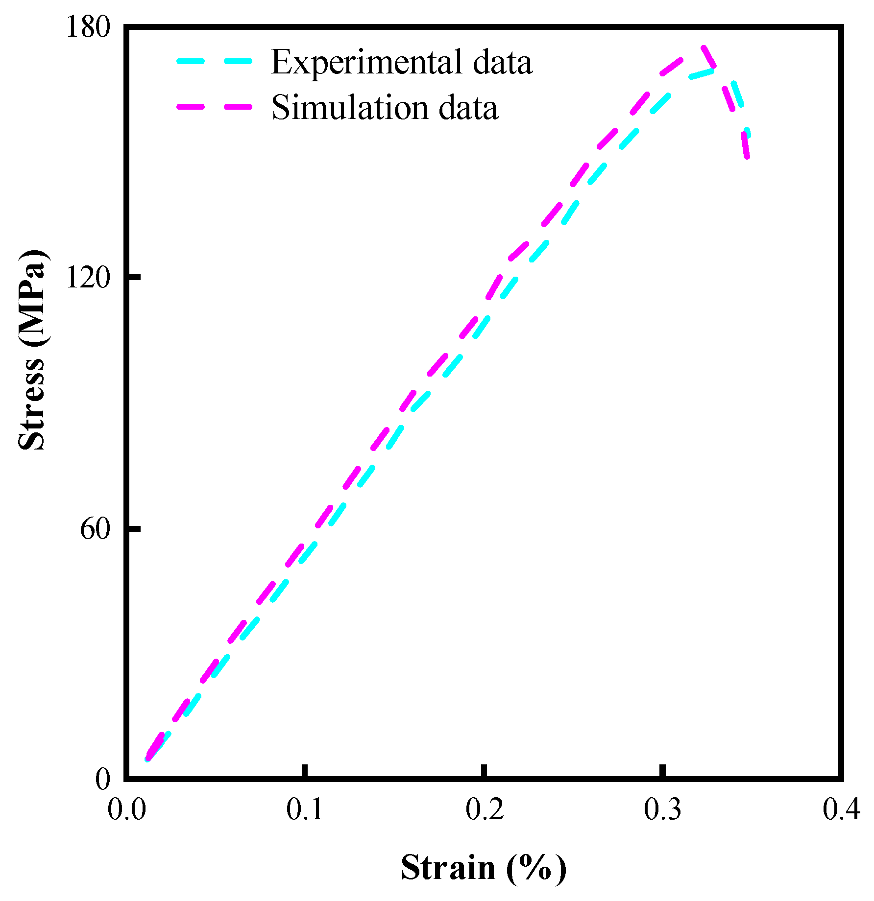
2.2. Granite Model Validation

To ensure the accuracy of the numerical simulation, uniaxial compression numerical simulation tests were performed on the established inhomogeneous granite model. During the simulation, the lower end of the rock model was fixed, and a downward velocity of 0.001 mm/s was applied to the upper end. The results of the comparison between the simulation and experimental results [31] are shown in Figure 3, and the obtained rock stress-strain data were compared with the experimental results in the literature [32], shown in Figure 4.
As shown in Figure 3 and Figure 4, the crack and stress-strain curves obtained after conducting uniaxial compression demonstrate remarkable agreement with experimental results. This consistency serves as a validation of the accuracy of the non-homogeneous granite model. Rock models play a crucial role in the numerical simulation of rock breaking. Among the commonly used models, the Mohr-Coulomb (M-C) and Drucker-Prager (D-P) models are widely adopted. In this study, the D-P model is employed [33], as it accounts for the hydrostatic pressure acting on the rock and provides a better explanation for the yielding phenomenon. The mathematical equation of the D-P model is as follows:
ρ I 1 + J 2 K = 0
I 1 = σ 1 + σ 2 + σ 3
J 2 = 1 6 [ ( σ 1 σ 2 ) 2 + ( σ 2 σ 3 ) 2 + ( σ 3 σ 1 ) 2 ]
ρ = 2 sin α 3 ( 3 sin α )
K = 6 e cos α 3 ( 3 sin α )
where ρ and K are experimental constants related only to the rock friction angle α and cohesion e.
PDC cutters break the rock mainly in shear, and the damage starts when the plastic stress of the rock exceeds its critical value. Neglecting the effect of the broken unit on the broken rock, the plastic strain criterion of the rock is:
ε r ε r l f
where εr is the equivalent plastic strain of the rock and εrlf is the equivalent plastic strain of the rock when damage occurs. I1 is the amount of stress in the first invariant, and J2 is the stress bias in the second invariant. σ1, σ2, and σ3 are the first, second, and third principal stresses, respectively.

3. Construction of the Model

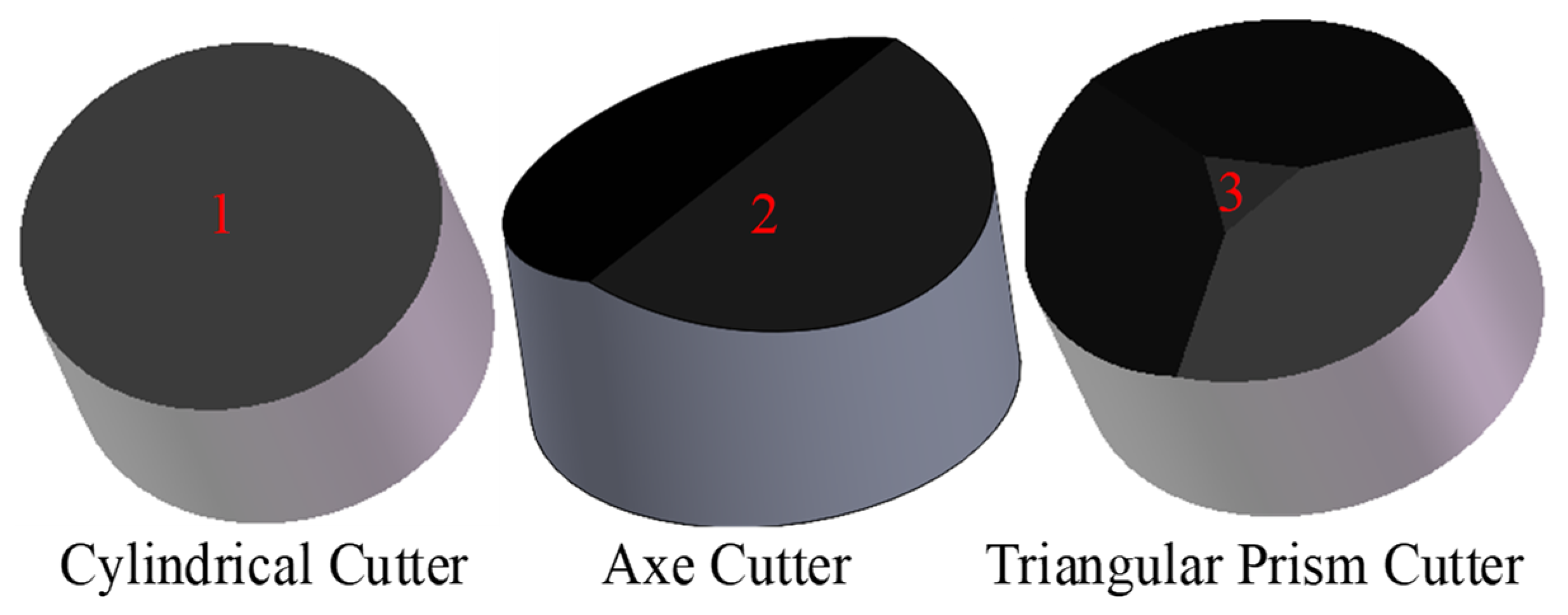
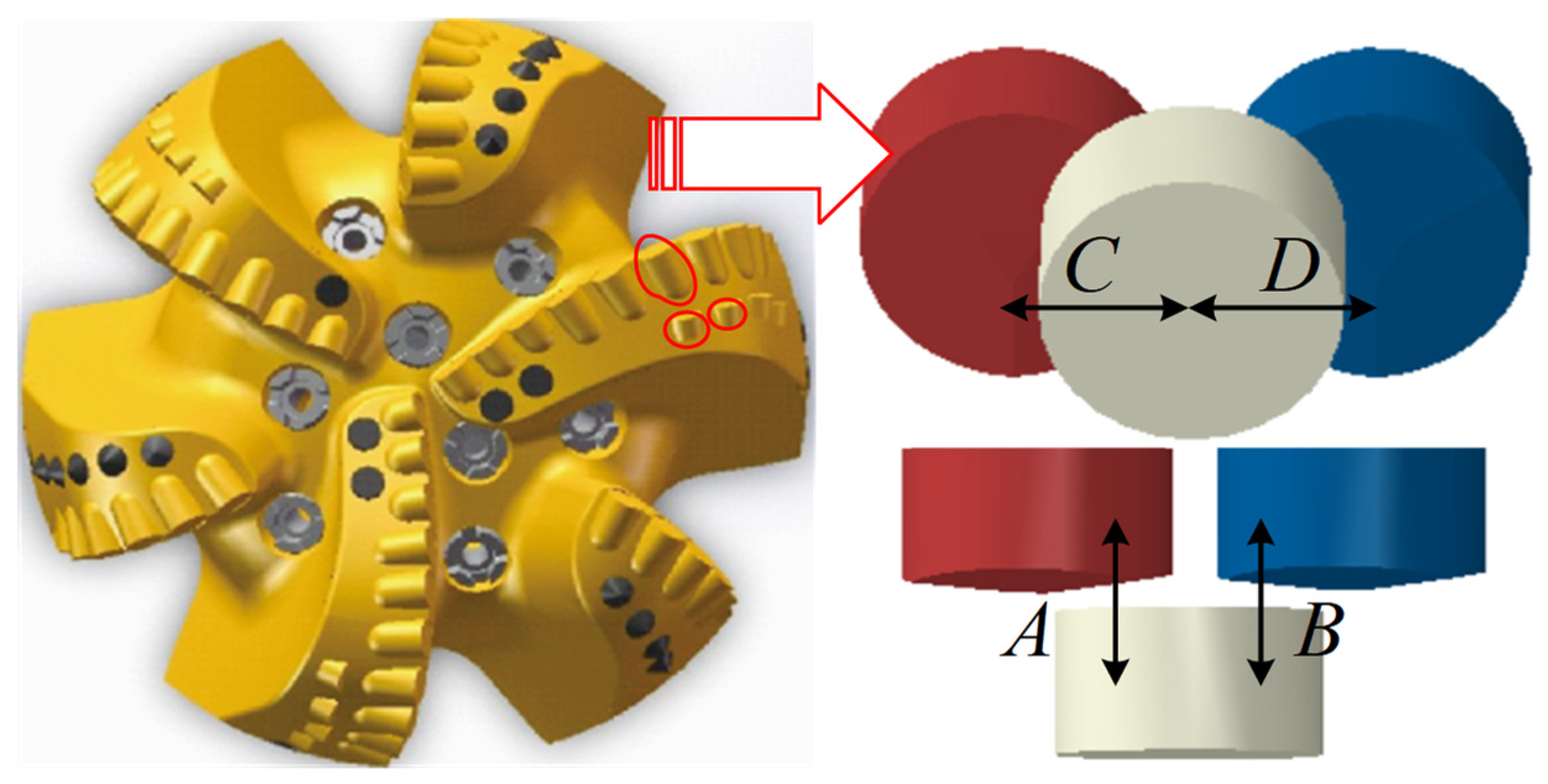
3.1. Simplification and Creation of 3D Models

In order to investigate the impact of a double-blade hybrid cutter arrangement on PDC drill bit performance, PDC cutters of three different shapes, namely cylindrical, axe, and triangular prism, were designed using SOLIDWORKS 2021 software. These cutters, each having a diameter of 13 mm and a height of 8 mm, were assigned respective numbers, shown in Figure 5. Specifically, the cylindrical cutter is denoted as number 1, the axe cutter as number 2, and the triangular prism cutter as number 3. The cutter parameters can be found in the literature [14,18]. The model of the PDC drill bit with double-blade tooth arrangement was simplified, and only some of the cutters in the front and back rows were retained for the subsequent study of the cutter layout scheme as well as the parameters. The model changes before and after the simplification are shown in Figure 6, where A and B are the longitudinal distance of the back row of cutters from the front row of cutters with a value of 10 mm, and C and D are the transverse distance of the back row of cutters from the front row of cutters with a value of 8 mm.

3.2. Finite Element Model Assumptions and Evaluation Guidelines

The rock-breaking process of PDC cutters is a highly intricate, non-linear phenomenon. In this study, the focus lies on investigating the rock-breaking performance of the cutter under various schemes and parameter combinations. In order to enhance computational efficiency, it becomes necessary to exclude secondary factors and make the following assumptions [16,23]: (1) Due to the difference in hardness between the PDC cutter and the rock material, the wear of the cutter during rock breaking is ignored and considered a rigid body. (2) The rock is removed immediately upon breaking, and repeated cutting is not considered. (3) The rotational motion of the cutter at the bottom of the well is considered a linear motion.
The interaction between the PDC cutter and the rock in the process of rock breaking is shown in Figure 7, assuming that the lateral and axial forces on the drill bit are Fx and Fy, respectively, and the PDC cutter penetrates the rock by the action of the pressure of Fy in the process of rock breaking and is destroyed by the rotation of Fx. In addition, its cutting surface is subjected to rock friction Fs, cutting reaction force Ft, and reaction force Fn along the axial direction; the bottom is subjected to rock reaction force Fb; α is the angle of inclination after cutting; d is the cutting depth; S is the stroke of the PDC cutter breaking rock; and the force balance equation is:
F x = F t + F n cos α + F s sin α
F y = F b + F n sin α + F s cos α
The cutting force and the mechanical specific energy of the PDC cutter in the process of rock crushing are important criteria for judging its performance [14,19]. The cutting force is the resistance of the PDC cutter in the direction of cutting the rock, and when the cutting force is lower, it means that the resistance of the cutter in the process of breaking the rock is smaller, the rock is easier to break, and the wear resistance of the cutter is stronger. The mechanical specific energy represents the energy consumed by the PDC cutter to crush the rock; the smaller the value, the higher the efficiency of the PDC cutter. Combined with Figure 7, the calculation formula for mechanical specific energy is:
M S E = W V = F t S l d S = F t l d
where MSE is the mechanical specific energy (J/cm3), W is the energy consumed by breaking rock (J), V is the volume of broken rock (cm3), and l is the width of the cutter (mm).
For the PDC bit, the ROP and the footage during rock breaking are effective criteria to measure its performance [26], and the higher ROP of the bit at a certain time means a greater feed rate and higher efficiency.

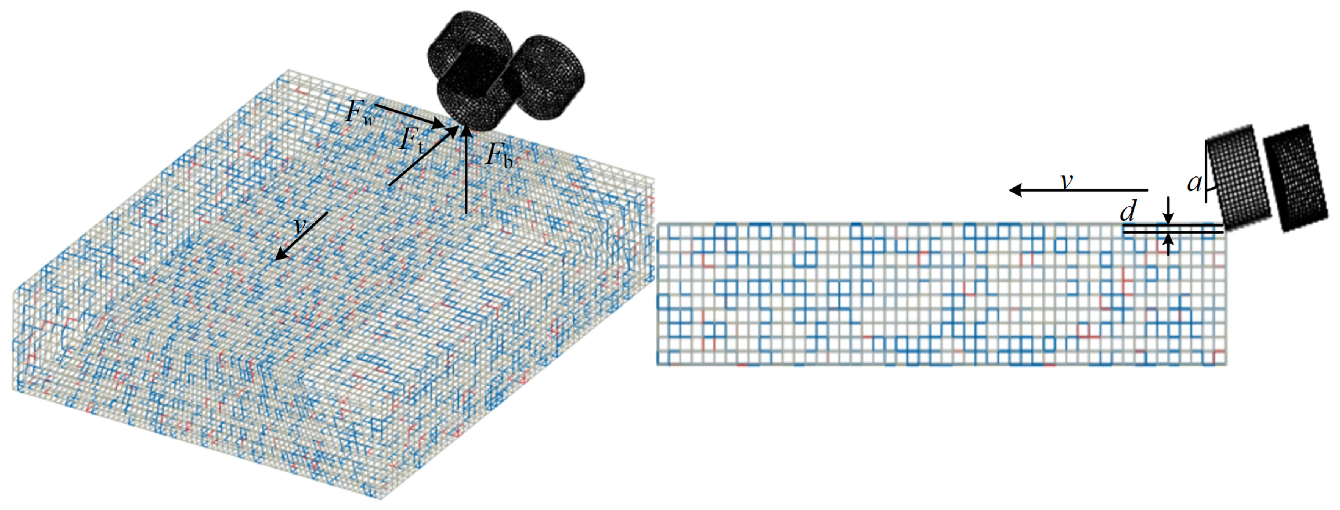
3.3. Finite Element Modeling

A finite element model of the mutual contact between the hybrid PDC cutter and the rock was constructed in ABAQUS2021 software and is shown in Figure 8, in which the preset back rake angle of each cutter is 15° and the depth of cut d is 1 mm, and the mesh size at the contact between the rock and the cutter is 0.8 mm and the size of the rest is 2 mm to take into account the calculation accuracy and efficiency. According to St. Venant’s principle, the cutting-rock contact size should be 5 to 10 times the cutter size; therefore, the size of the rock is 100 mm × 80 mm × 20 mm. The speed of the PDC cutter along the cutting direction is set at 1 m/s, except for the rock surface and upper surface along the cutting direction of the cutter; the rest of the rock surface is fixed. To prevent the non-convergence phenomenon in the simulation process, the frictional contact relationship between the tool surface and the rock node is established in advance, and the friction factor is set to 0.25. The material parameters of the cutter during the simulation are: density 3600 kg/m3, modulus of elasticity 750 GPa, Poisson’s ratio 0.07, and the materials used in the rock are shown in Table 1 above.

4. Results and Discussion

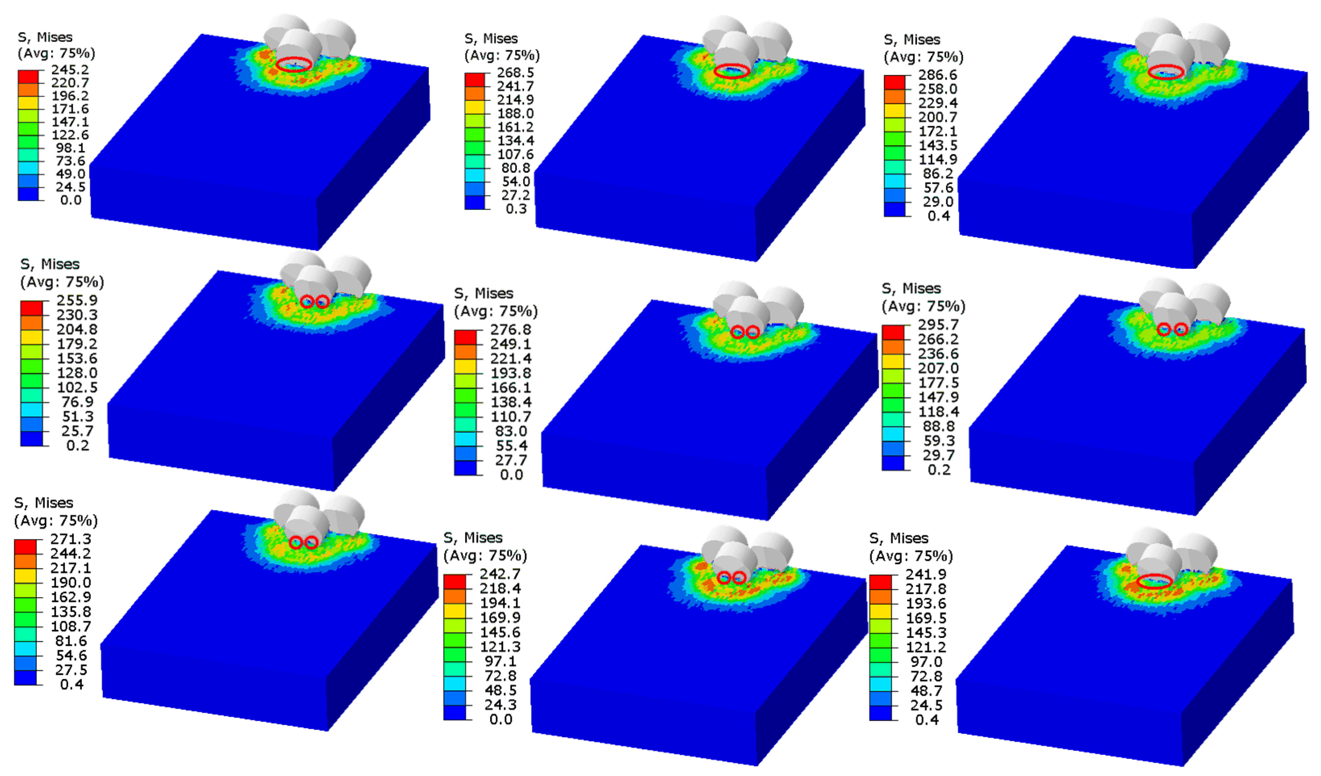
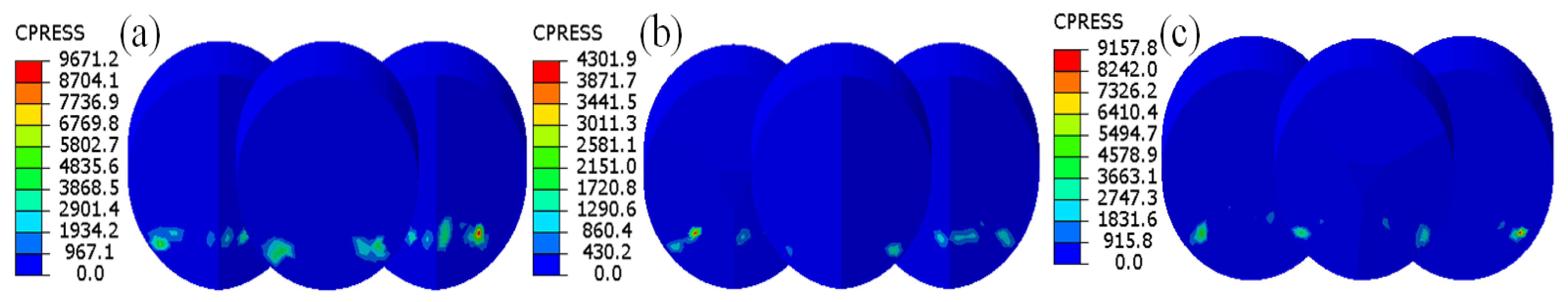
4.1. Rock-Breaking Characteristics Analysis

The stress contour maps, expressed in MPa, during the rock-breaking process when the cylindrical, axe, and triangular prism cutters are utilized as the front row correspond respectively to the first, second, and third rows depicted in Figure 9. Due to the difference in cutter structure, the cylindrical cutter mainly uses the edge to shear the rock, while the axe and triangular prism cutters have a convex ridge-like structure that not only shears the rock but also crushes the center of the rock. Hence, the rock-breaking efficiency of the axe cutter and the triangular cutter surpasses that of the cylindrical cutter.
The red circle in Figure 9 evidently demonstrates that the cylindrical cutter, due to shearing, contacts a larger volume of rock compared to the remaining two cutters, which may lead to a change in the damage mode of the rock from plastic small block damage to large block shedding. This causes the cutter to repeatedly cut the rock chips, resulting in a decrease in the efficiency of the bit and an increase in the probability of vibration. The axe cutter has a convex ridge-like structure, and when it comes in contact with the rock, it splits the rock and distributes it on both sides of the cutter, effectively solving the problem of rock balling, which can make the rock break in a smaller volume compared to the cylindrical cutter and improve the rock breaking efficiency. Comparing the maximum stress in the contour, it is found that the stress on the rock is significantly greater when the axe cutter is used as the front row. Upon computation, it has been discovered that the maximal stress experienced by rocks when fractured using an axe cutter shows an increase of 8.9% and 3.2% when compared to fracturing with a triangular prism cutter and a cylindrical cutter, respectively. This observation implies that an axe cutter can more easily reach the yield stress of rocks, thus effectively addressing the issue of a cylindrical cutter struggling to penetrate hard rocks. It indicates that the contact between the axe cutter and the rock is more likely to reach the yield stress of the rock, which can solve the problem that the cylindrical cutter does not easily penetrate the hard rock. The rock-breaking mode of the triangular prism cutter is similar to that of the axe cutter, but the crushing effect on the rock is not as strong as that of the axe cutter. From the comparison of the red circle position in the figure, it can be found that the rock separation effect under the action of the triangular prism cutter is not as obvious as that of the axe cutter.
A comprehensive analysis of the rock-breaking characteristics of the cutters mentioned above reveals that axe cutters are suitable for the front row of the cutter blades of the PDC drill bit, and cylindrical and triangular prism cutters may be more suitable for the back row.

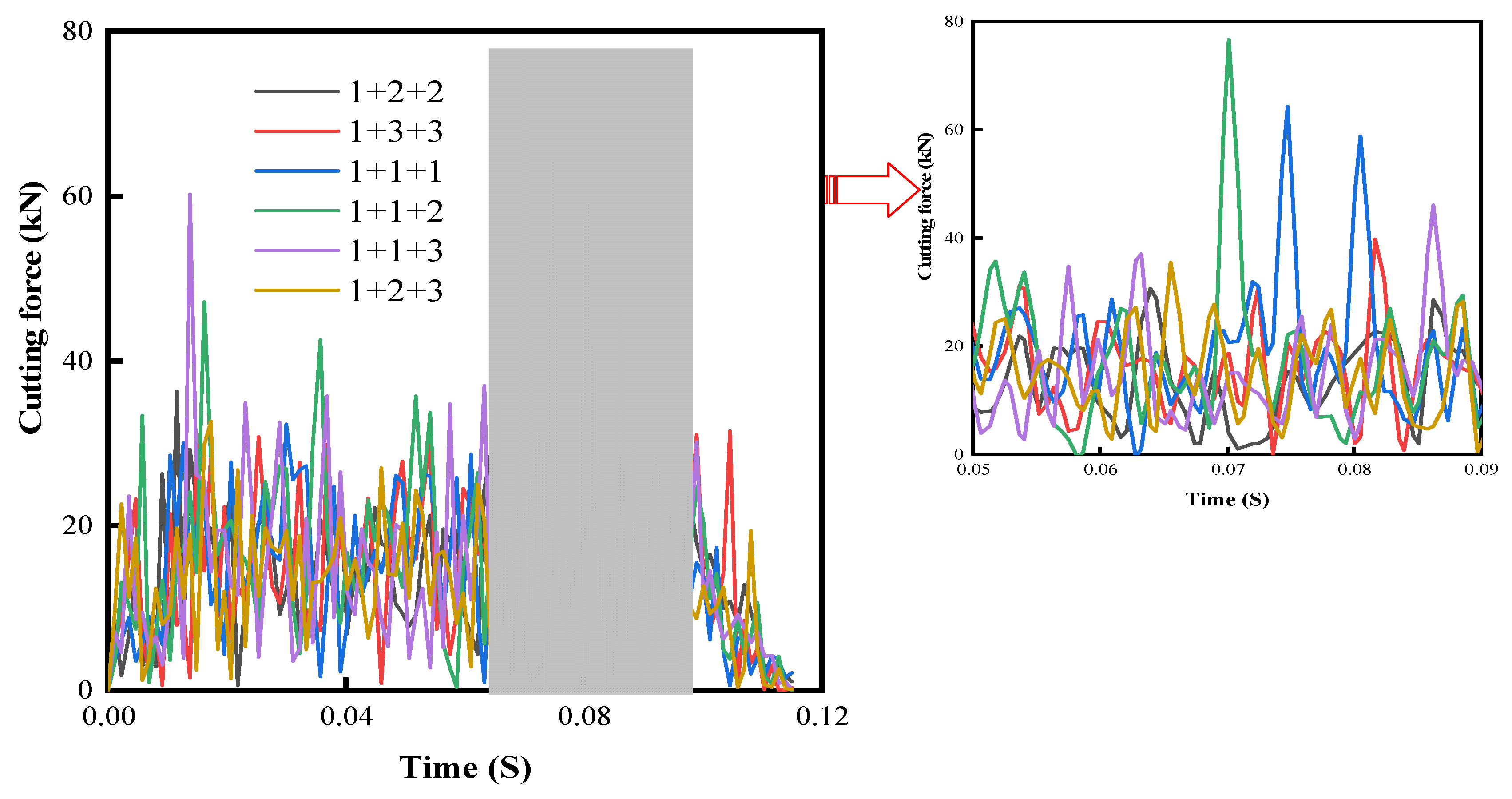
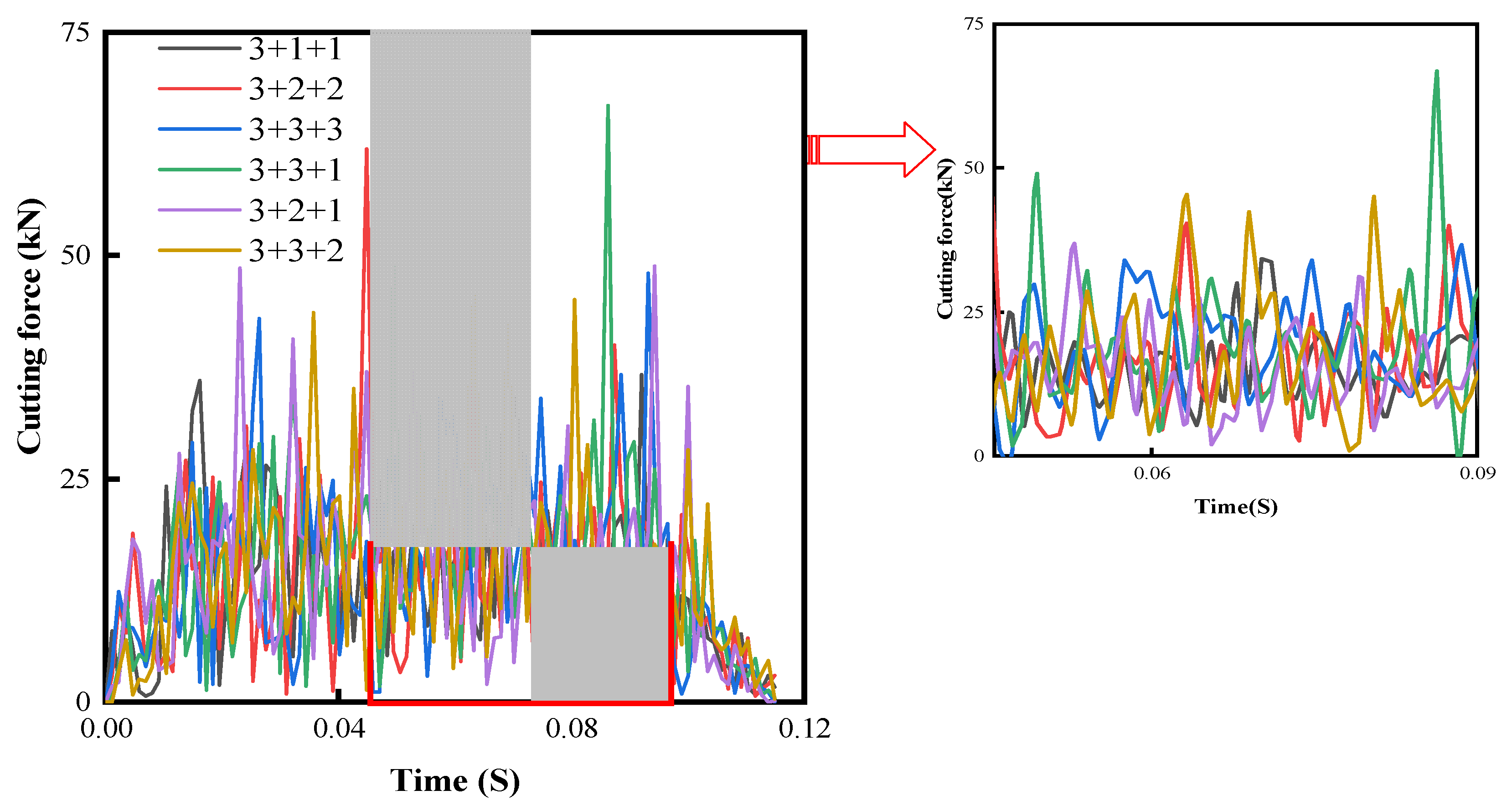
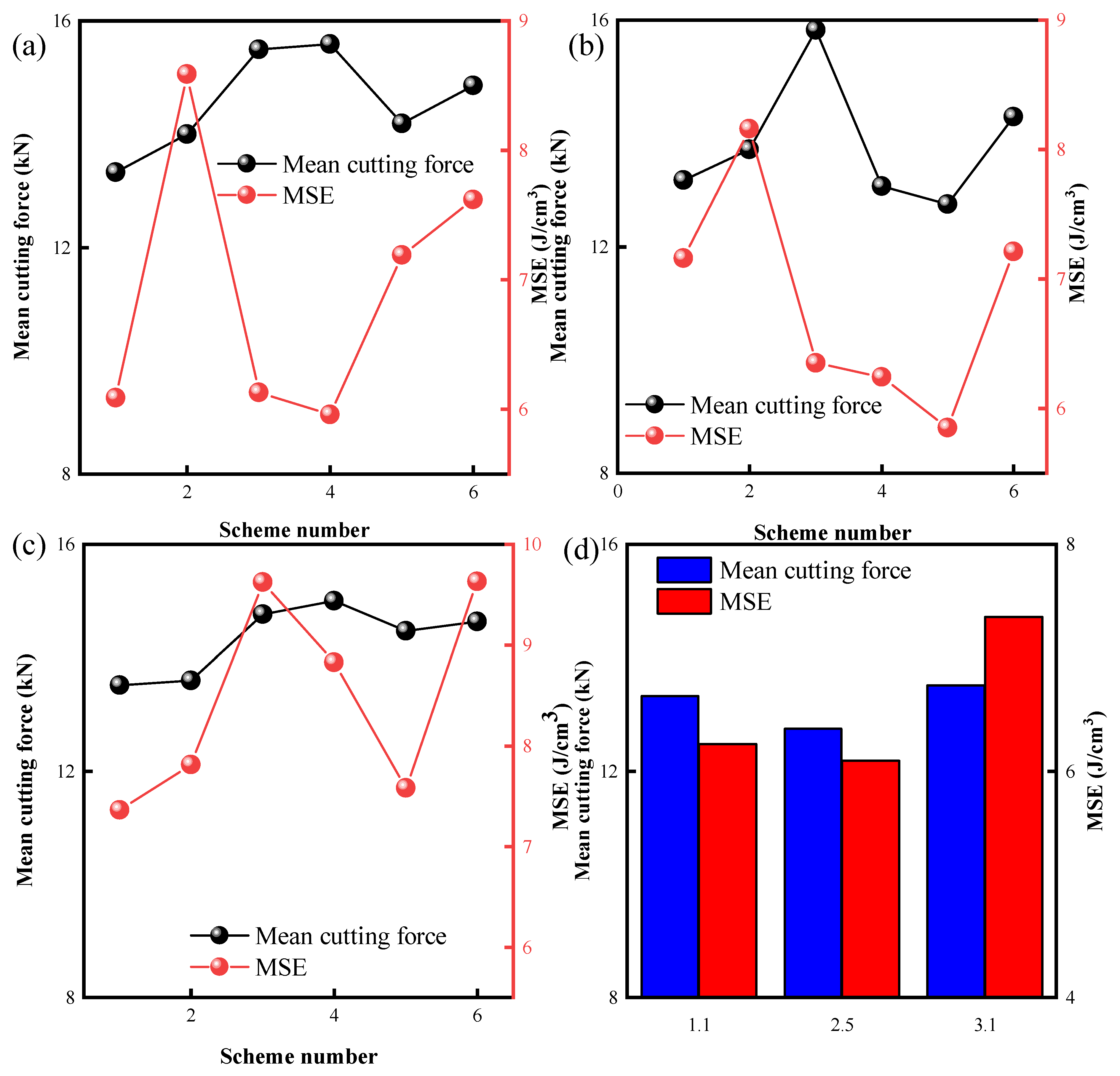
4.2. Cutting Force Analysis

To find the best cutter arrangement scheme, 18 different combination schemes of cylindrical (No. 1), axe (No. 2), and triangular prism (No. 3) cutters were numerically simulated. The scheme numbers in Figure 10, Figure 11 and Figure 12 have the following implications: Taking “1 + 2 + 2” as an example, the first digit represents the cutter arrangement type of the front row of the drill bit. The second and third digits represent the cutter arrangement types of the rear row of the drill bit, with the second digit indicating the left-side cutter arrangement type of the rear row and the third digit indicating the right-side cutter arrangement type of the rear row. The cutting force curves corresponding to the six strategies utilizing cylindrical cutters in the frontal row are shown in Figure 10. As evidenced in the figure, the application of cylindrical cutters as the leading row has a considerable impact on the overall cutting force under varying rear row arrangements. In instances where the rear row incorporates a cylindrical cutter, the cutting force exhibits a notably amplified peak and fluctuation compared to the other arrangements.
The underlying cause of this occurrence is predominantly linked to the fracturing properties of the cutter. Being flat, the cutting face of the cylindrical cutter relies primarily on its periphery’s shear force to split the rock. However, it encounters considerable difficulty when presented with more rigid rock types. Additionally, incorporating excessive numbers of cylindrical cutters into the arrangement can complicate the drilling process, leading to heightened resistance. These conditions can significantly compromise the overall efficiency and lifespan of the drill bit.
As shown in Figure 10, the optimal configuration utilizes the cylindrical cutter in the front row, followed by the axe cutter, resulting in a substantial reduction in overall cutting force fluctuations and peaks. This outcome is primarily due to the cylindrical cutter’s pre-crushing effects on the rock in the front row. Meanwhile, the axe cutter not only exerts a shearing impact on the rock but also induces an additional crushing effect. Consequently, this setup enhances penetration into granite structures compared to exclusively using cylindrical cutters, thereby minimizing resistance.
Figure 11 shows the various force curves associated with the axe cutter in the vanguard position across six assorted scenarios. Upon comparison with data from Figure 10, it is concluded that when the axe cutter operates in the front row, it yields lesser stress peaks in all scenarios, as opposed to when the cylindrical cutter is placed in the same position. This is attributable to the axe cutter’s superior capacity to induce a crushing effect on rock compared to the cylindrical cutter. Consequently, this facilitates more efficient granite penetration in its initial phases, engenders an enhanced pre-crushing influence, and alleviates formation stress. This sequence of events collectively enables subsequent rows of cutters to crush rock more effortlessly.
The data presented in Figure 11 reveals an imperfect effect of utilizing both front and rear row axe cutters. This is largely due to the resultant interference in the force exerted by the front row cutters when the rear row attempts to crush the rock, causing instability and a significant fluctuation in the overall cutting force, therefore hindering the anticipated effect. However, when the frontal row is equipped with an axe cutter and the rear row consists of a triangular prism cutter and an axe cutter, the peak and fluctuation of cutting forces attain a minimal level. This is attributed to the weaker impact of the triangular prism cutter on the rock, resulting in less interference with the front row’s performance. The harmonic interplay between the two cutter types yields a more optimal result.
Figure 12 shows the cutting force trajectories for six diverse layouts, each deploying a triangular prism cutter in the front row. The data underscore that using a triangular prism cutter at the forefront and an axe cutter in the rear row results in a reduction in overall cutting force fluctuation and peak. When contrasted with the cylindrical cutter and axe cutter arrangement, this setup experiences a comparatively lower cutting force. This can be attributed to the effective crumble impacts on the rock exerted by the triangular prism cutter, which facilitate the breakdown of the granite with relative ease. Yet, when an axe cutter is positioned in the front row, the total cutting force reaches its optimal low point. This observation substantiates the analysis depicted in Figure 9 concerning the rock-fracturing attributes of the cutter.

4.3. Mechanical Specific Energy Analysis

Figure 13a–c, respectively, show the mechanical specific energy (MSE) and average cutting force across various circumstances, employing circular, axe, and triangular prism cutters as the primary row. It should be noted that the arrangement of the scenario markers follows the same sequence as that in the cutting force legend. Additionally, Figure 13d presents the aggregate values of both the cutting force and MSE for the optimal solution, wherein three different cutters occupy the front row. The data depicted in Figure 13a indicates that the minimum aggregate values of cutting force and MSE arise when the front row is assembled with a cylindrical cutter and the rear row is exclusively composed of axe cutters. Similarly, Figure 13b shows the most effective combination being an axe cutter in the front row teamed with a mix of triangular prism cutters and axe cutters. On the other hand, Figure 13c demonstrates that the triangular prism cutter in the front row combines best with an axe cutter. Reviewing data across all figures, Figure 13d acknowledges the superior choice to be an axe cutter in the front row and a triangular prism cutter in the rear row when compared with the previous three combinations.
Figure 14a–c delineate the contact stress contours in optimal conditions, corresponding to the front row setup using cylindrical, axe, and triangular prism cutters, respectively. Comprehensive evaluation of these contours reveals the least overall cutter stress with an axe cutter in the front row, followed by moderately increased stress when the triangular prism cutter occupies the front row. The highest cutter stress is observed when the cylindrical cutter is placed in the front row.
The rationale behind these observations lies in the aggressive nature of the axe cutter, which swiftly releases stratigraphic stress upon contacting rock. As a result, the rear row of cutters can fracture the rock with relative ease. However, the cutter experiences the highest stress levels in the rear row, thereby making an axe cutter the optimal choice for the front row to minimize total cutter stress.

5. Cutter Spacing Optimization and Bit Rock Breaking Simulation

To optimize the hybrid cutter layout, it is crucial to prudently select the spacing between the sequential rows of cutters. The cutter spacing parameters, as illustrated in Figure 6, encompass four parameters. The manual modification of these parameters for simulation purposes can yield an excessive number of permutations and, possibly, the absence of the desired results. To circumvent this issue and maximize the rock-breaking efficiency of the hybrid cutter arrangement, the Box-Behnken response surface methodology [34] was implemented for the optimization of cutter spacing.

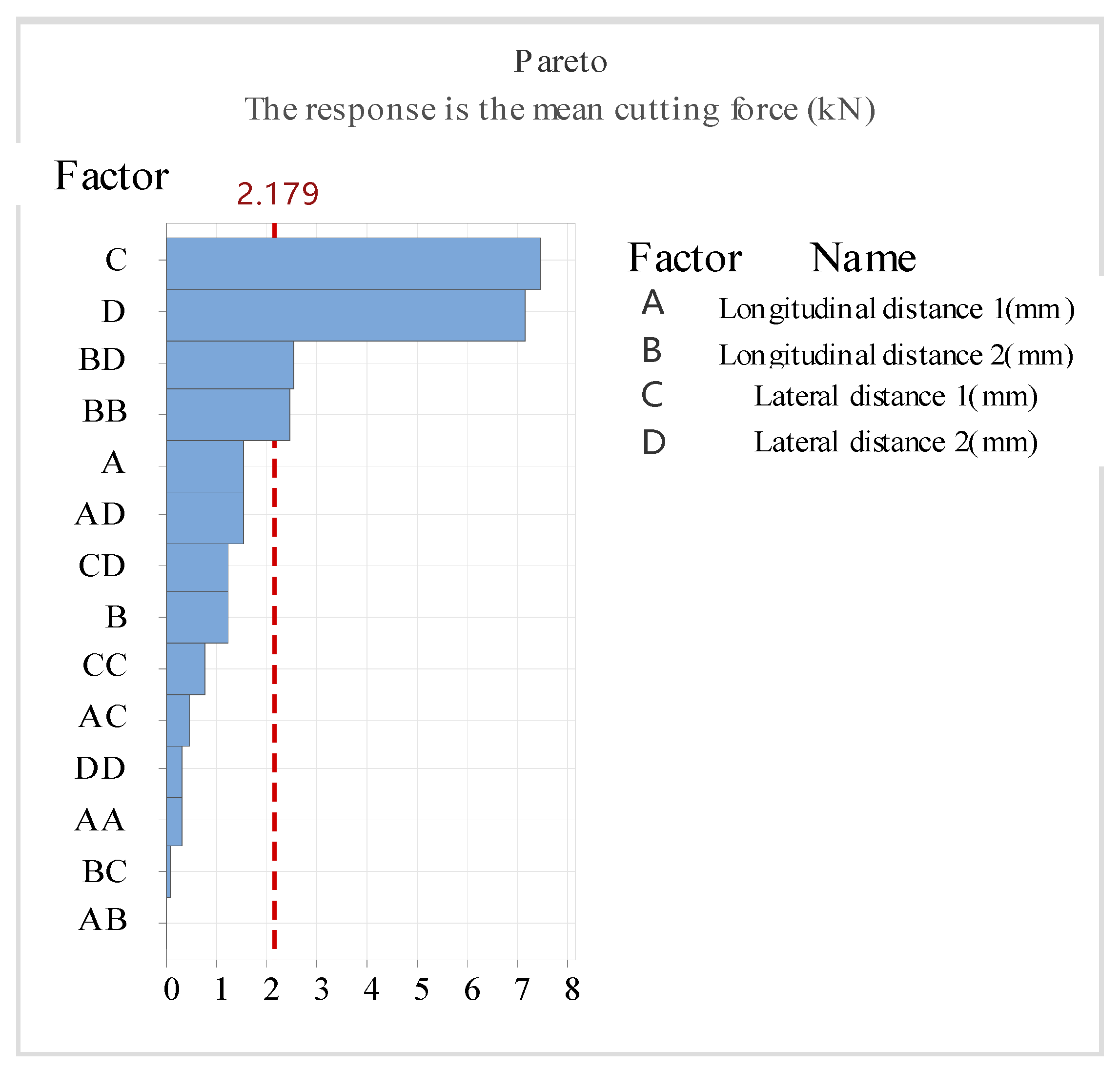
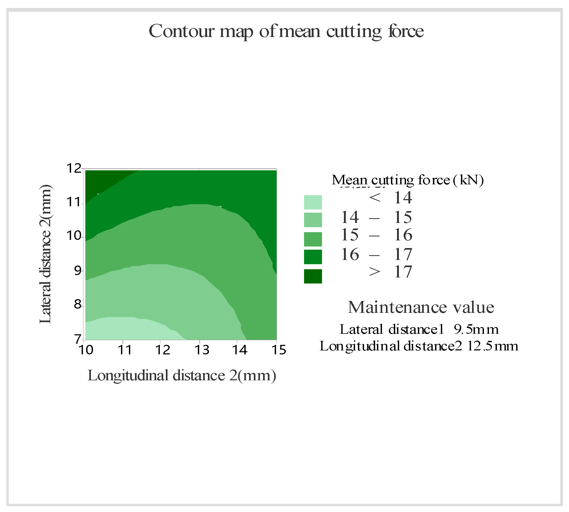
5.1. Analysis of Sampling Results

For this study, scenarios involving a front row of axe cutters and a rear row of triangular prism cutters were examined. The design variables considered were the longitudinal distances (1(A) and 2(B)) and the transverse distances (1(C) and 2(D)) of the front and rear rows of the cutters, as depicted in Figure 6. The target variable was the mean cutting force applied to the whole cutter (E). Utilizing the Box-Behnken method for sampling, 17 sets of numerical simulations were conducted, with the results illustrated in Table 2.
As shown in Table 2, there is a notable fluctuation in the cutter’s force values across differing spatial cases that underscores the significance of optimization. A comprehensive analysis, conducted utilizing MINITAB 2021 software, yielded the Pareto weight plot, which provides elucidation on the impact exerted by each distinct design variable on the objective. This is illustrated in Figure 15, where variables exceeding the delineated red line have a considerable bearing on the design objective. In particular, the interaction between transverse distances 1 and 2, coupled with the interaction between longitudinal distance 2 and transverse distance 2, proves consequential in influencing the aggregate mean value of the cutter’s force.
In order to streamline the analysis of factor B and D interactions, a contour plot juxtaposing the two factors and the mean value of the cutting force was constructed, as shown in Figure 16. The data indicate that an augmentation of both transverse distance 2 and longitudinal distance 2 is associated with an escalation in the cutter’s cutting force. As such, to curtail the cutting force exerted on the cutter, the transverse distance between the anterior and posterior rows of cutters should be meticulously maintained at 7 mm to 7.5 mm, while the longitudinal distance should range between 10 mm and 12.5 mm. With respect to the impact factor’s weight on the target value, the MINITAB software was employed to develop a correlation between the design variables and the target values. The derived expression is as follows:
E = 0.7 + 1.52 A 1.44 B 0.5 C + 2.35 D 0.0139 A 2 + 0.114 B 2 + 0.0374 C 2 + 0.0145 D 2 0.0018 A B 0.0264 A C 0.082 A D + 0.0051 B C 0.1347 B D + 0.0654 C D

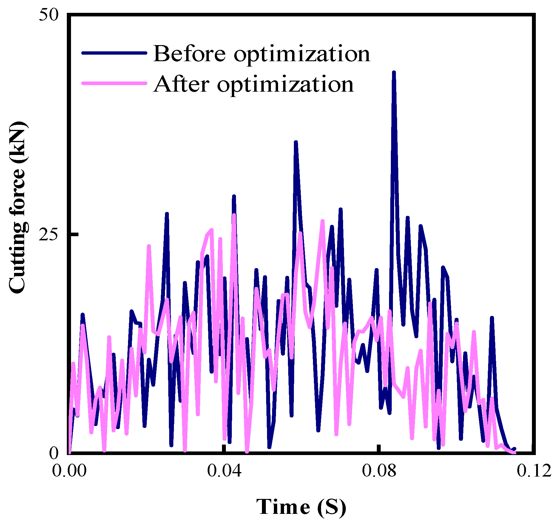
5.2. Analysis of Optimization Results

Drawing from the correlation between the gleaned design variables and the target quantity and with an objective to optimize the minimum mean cutting force, an optimized mean cutting force of 11.68 kN is achieved when the resultant longitudinal distance 1 measures 10 mm, longitudinal distance 2 records 10.06 mm, and transverse distances 1 and 2 both equal 7 mm. A numerical simulation of the rock-breaking cutter based on the established parameters and its comparison to the cutting force from the pre-optimized scheme are shown in Figure 17. The data reveal that the peak and fluctuation in cutting force exerted by the optimized cutter during the rock fracturing process are considerably smaller than those experienced prior to optimization. This suggests that the optimized cutter design encounters less resistance, thereby demonstrating enhanced effectiveness in the rock-breaking process. The average cutting force exerted by the optimized cutter is computed to be 10.96 kN, which signifies a reduction of approximately 13.7% in comparison to the 12.7 kN experienced before optimization. Furthermore, the deviation between the optimized forecasted value and the simulated value is merely 6.2%, thereby affirming that the derived mathematical model is significantly reliable.
To further substantiate the beneficial role of the optimized cutter arrangement scheme in enhancing the drill bit’s efficiency, finite element models of rock breaking using pre- and post-optimized cutter arrangement schemes were established in the ABAQUS software. In these models, the mesh size at the contact point between the drill bit and rock is 4 mm, while 12 mm is used elsewhere, as shown in Figure 18a. A WOB of 80 kN and a rotational speed of 210 r/min are applied to the drill bit, with the rock surfaces, except the superior one, remaining fixed. The footage of the PDC drill bit using pre- and post-optimized cutter arrangement schemes is depicted in Figure 18b. The drill bit using the post-optimization cutter arrangement scheme demonstrates superior penetration capacity, attributable to the reduced cutting force from cutter layout optimization, which consequently decreases the resistance encountered during rock breaking and improves the footage of the drill bit. Based on numerical calculations, the footage of a drill bit using a post-optimized cutter layout can reach 263.6 mm, compared to 239.8 mm pre-optimization, indicating a 9.9% improvement in footage. The data imply that a drill bit optimized with the cutter arrangement scheme does not manifest high efficiency in the initial stage of rock breaking but rather in the middle and later stages. As the depth of rock broken by the drill bit increases, the post-optimized cutter arrangement scheme gradually displays higher efficiency than the pre-optimized scheme, suggesting its greater suitability for deep and hard stratum drilling.

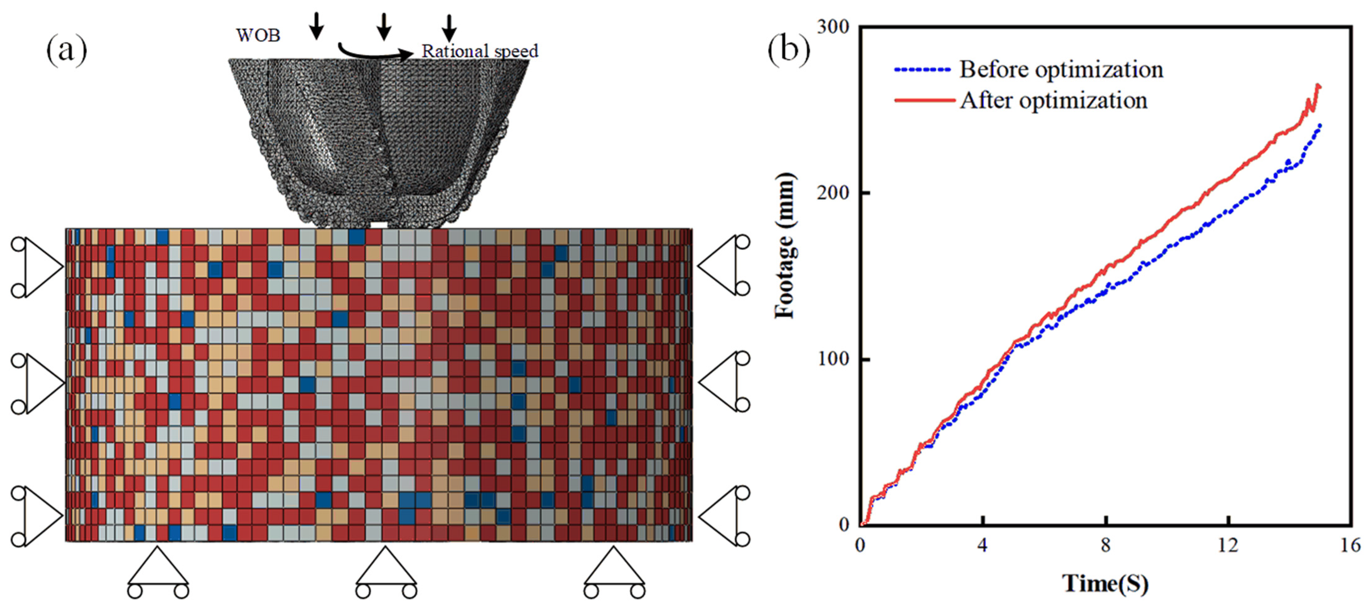
5.3. Full-Size Bit Rock Breaking Simulation

To fully understand the rock-breaking effect of the obtained optimal solution, the cutting structure of the PDC bit embedded by a triangular prism cutter, axe cutter, and mixed triangular prism and axe cutter with a diameter of 215.9 mm was established, respectively, and the related finite element model was constructed in ABAQUS software as shown in Figure 19, with a formation diameter of 600 mm and a height of 300 mm. The layout of the cutter on the bit follows the principle of equal cutting volume: the grid size of the cutting structure of the bit is 4 mm, the size of the contact with the rock is 4 mm, and the grid size of the rest of the rock is 12 mm. The wear of the cutting structure of the bit is ignored in the simulation process, and it is considered a rigid body. The cutter is arranged with a back rake angle of 15° and a side rotation angle of 0°. Its rotation and vertical motion in the well are considered. The WOB is 80 kN, and the RPM is 210 r/min. The rock is fixed except for the upper surface, and the simulation time is 15 s.
The contact between the simulated bit and the rock is a highly nonlinear process that includes: (1) Material nonlinearity: the rock begins to deform plastically when it is subjected to more than the maximum stress it can withstand. (2) Geometric nonlinearity: The position of the bit is constantly changing during the interaction between rock and bit contact. (3) Contact nonlinearity: The contact surface between the bit and the rock is constantly changing as the rock disappears after breaking during the simulation. The above nonlinear process can cause the simulation to be difficult to converge. Based on D’Alembert’s principle, the mechanical model of the contact process between the drill bit and the rock is established as follows:
( T Q 0 0 T Y ) { A t Q A t Y } + ( C Q 0 0 C Y ) { V t Q V t Y } + ( K Q 0 0 K Y ) { U t Q U t Y } = { S t Q F t Q S t Y F t Y }
where T is the overall mass matrix of the finite element model; C is the overall damping matrix of the finite element model; K is the overall stiffness matrix; A is acceleration; V is velocity; U is displacement; St is the WOB vector; Ft is the contact force vector; the subscript Q represents the PDC cutter; and Y represents the rock.
The dependability of the full-scale drill bit simulation outcomes was authenticated by applying a PDC bit equipped with an axe cutter with a WOB of 60 kN, an RPM of 90 r/min, and a simulation duration of 1 s. Subsequently, the mechanical ROP curve was acquired, as shown in Figure 20a, and the mean ROP was computed at 11.615 mm/s. Following this, a constant mechanical ROP of 11.615 mm/s was administered to the bit, with the resultant reaction force illustrated in Figure 20b. Under constant WOB, the average reaction force exerted on the bit was calculated to be 47.65 kN, while the same under constant ROP was 51.92 kN. Observing a discrepancy of 8.9% between the two values provided partial validation of the numerical simulation’s precision.
Figure 21 delineates the rock stress contour during and subsequent to the completion of rock fragmentation for the three bits. It can be inferred from the contour that the bit implemented with mixed cutters exerts the maximum stress on rock action, thus indicating that the PDC bit with mixed cutters can more effortlessly attain the yield stress of the rock during drilling. This renders the penetrating and fracturing of the granite more efficient while mitigating the stick-slip phenomenon to a considerable extent. Additionally, interpreting the visuals, it is quite perceptible that the PDC bit with a mixed cutter configuration exhibits the most prominent displacement in feed. The variance in feed between the bit with a triangular prism cutter layout and the bit with an axe cutter layout is marginal, substantiating that the bit with a mixed cutter configuration can engender a more advantageous effect.
Figure 22a shows the bit footage curves of the three PDC bits during the rock fragmentation process. It is discernible from the data represented that the PDC bit equipped with a mixed cutter configuration has a notably superior bit footage, followed by the bit with a triangular prism cutter layout, while the bit with an axe cutter arrangement finishes last. While the axe cutters are more incisive, the triangular prism cutters possess a symmetric structure, and the force distribution during rock fragmentation is more balanced. This balance contributes to the stability of the drilling process; hence, efficiency is augmented. The reflected data from Figure 22a also demonstrates that due to the rigidity of the granite, the bit exhibits displacement in the opposite direction of the applied WOB during rock fragmentation, stemming from the inability to drill, which adversely impacts the drilling process. However, the PDC bit with mixed cutter configuration exhibits lesser displacement fluctuation, indicating a lower bounce propensity during drilling and the capability to better maintain the stability of WOB and ROP. From the calculations conducted, the footage of the PDC bit with a mixed cutter configuration is higher by 16.6% and 16.8% when compared to the PDC bit with a triangular prism cutter and axe cutter, respectively.
Figure 22b shows the instantaneous ROP fluctuation curve throughout the drilling process of the bit. The data indicates that the drill bit outfitted with a mixed cutter arrangement experiences the least velocity variance during the drilling operation, suggesting that this bit configuration penetrates granite with greater ease during drilling. This could potentially reduce drill bit stick-slip incidents, thereby enhancing overall efficiency and prolonging the lifespan of the bit. These observations are in accordance with previous analyses of bit footage. Based on calculations, the ROP exhibited by the PDC bit with a mixed cutter arrangement is elevated by 23.5% and 21.1% compared to that of the axe and triangular prism PDC bits, respectively. In addition, the numerical simulation of rock breaking by full-size drill bits shows that the triangular prism cutter, due to the symmetry of its structure, presents a better rock-breaking effect than the axe cutter in the actual drilling process. This is consistent with the results in the literature [35].
Through calculating the maximum, minimum, variance, and standard deviation of rate of penetration (ROP) for three types of drill bits, the stability of their rock-breaking performance was quantified, as shown in Table 3. The data indicated that the difference between the maximum and minimum speeds of the PDC drill bits using axe cutters, triangular prism cutters, and a mixed arrangement of cutters was 122.11 mm/s, 93.54 mm/s, and 46.72 mm/s, respectively. This implies that due to the symmetry of the structure, the ROP fluctuations of drill bits with triangular prism cutters were smaller than those with axe cutters, leading to a more stable rate of penetration. The ROP fluctuations of drill bits with a mixed cutter arrangement were even smaller, resulting in an even more stable drilling process. The variance and standard deviation measure the dispersion degree of drill bit ROP, further quantifying the stability of rock-breaking performance. In particular, PDC drill bits utilizing axe cutters showcased the highest ROP dispersion degree, while PDC drill bits with a mixed cutter arrangement showcased the lowest ROP dispersion degree. Compared to drill bits with axe cutters, the standard deviation of the ROP for drill bits with triangular cutters decreased by 18.5%, whereas drill bits with a mixed cutter arrangement showcased a decrease in the standard deviation of the ROP by 53.6% and 43.08%, respectively, relative to drill bits with axe cutters and triangular prism cutters. This illustrates that a mixed cutter arrangement can maintain the stability of rock breaking, consequently sustaining the WOB stability, which ultimately contributes to the improved efficiency and increased lifespan of the drill bit.

5.4. Field Applications

In order to validate the findings of the study, empirical fieldwork was conducted at the Tahe oilfield in China, utilizing a bit equipped with a triangular prism Polycrystalline Diamond Composite (PDC) cutter as well as a PDC bit with a mixed cutter configuration. The performance of both the bit with a triangular prism cutter and the one featuring mixed cutters was compared in terms of efficacy while keeping the drilling parameters, formation characteristics, and other conditions largely uniform.
Figure 23 shows a comparative analysis between the pre-usage and post-usage stages of a bit outfitted with a triangular prism PDC cutter, while Figure 24 shows the same for a bit featuring a mixed cutter arrangement. Notably, subsequent to the completion of drilling, both categories of bits maintained an impressive freshness rate exceeding 85%, with no evidence of chipping or any instances of incorrect cutter usage reported.
In the practical usage comparison between the two types of bits in terms of their respective drilling depth and rate of penetration (ROP), as shown in Figure 25, the PDC bit augmented with a mixed cutter arrangement manifests an ROP of 2.1 m/h, signifying an impressive enhancement of approximately 23.5% when juxtaposed against the 1.7 m/h ROP of the PDC bit complemented with triangular prism cutters. This ROP improvement is notably congruent with the resultant data procured from numerical simulations. In the context of drilling depth, the PDC bit with a triangular prism cutter records a level of 275.1 m, whereas the bit equipped with a mixed cutter arrangement registers a substantially higher drilling depth of 370.1 m, indicating a remarkable increase of 34.5% in comparison to the alternative PDC bit.
The experimental results were compared with the simulation results. The data demonstrates that the ROP of the cutters arranged in a mixed layout improved by approximately 23.5% compared to the bit with a triangular prism cutter. However, under simulation conditions, the ROP for the drill bit using the mixed cutter arrangement increased by about 21.1% compared to the bit with a triangular prism cutter. The variation between the two ROP improvements is around 10.5%, exemplifying the reliability of the numerical simulation results. Similarly, the comparison of rock-breaking effects of drill bits pre- and post-optimization of cutter arrangement schemes by numerical simulation using the Box-Behnken method is also reliable. This signifies that optimizing relevant parameters of the cutter arrangement scheme with the Box-Behnken method could effectively provide design parameters for field drilling operations.

6. Conclusions

In this paper, a finite element model of heterogeneous granite was constructed with the Drucker-Prager criterion employed for rock failure. The accuracy of the rock model was validated through uniaxial compression simulations. The impact of different combinations of axe, triangular prism, and cylindrical PDC cutters on rock-breaking efficiency was analyzed, with optimization of cutter spacing parameters under the optimal scheme using the Box-Behnken approach. The rock-breaking efficiency of the PDC drill bit with the optimal cutter arrangement was compared with that of single triangular prism and axe drill bits. The feasibility of the simulation results was verified through field experiments. The following conclusions can be drawn:
(1)
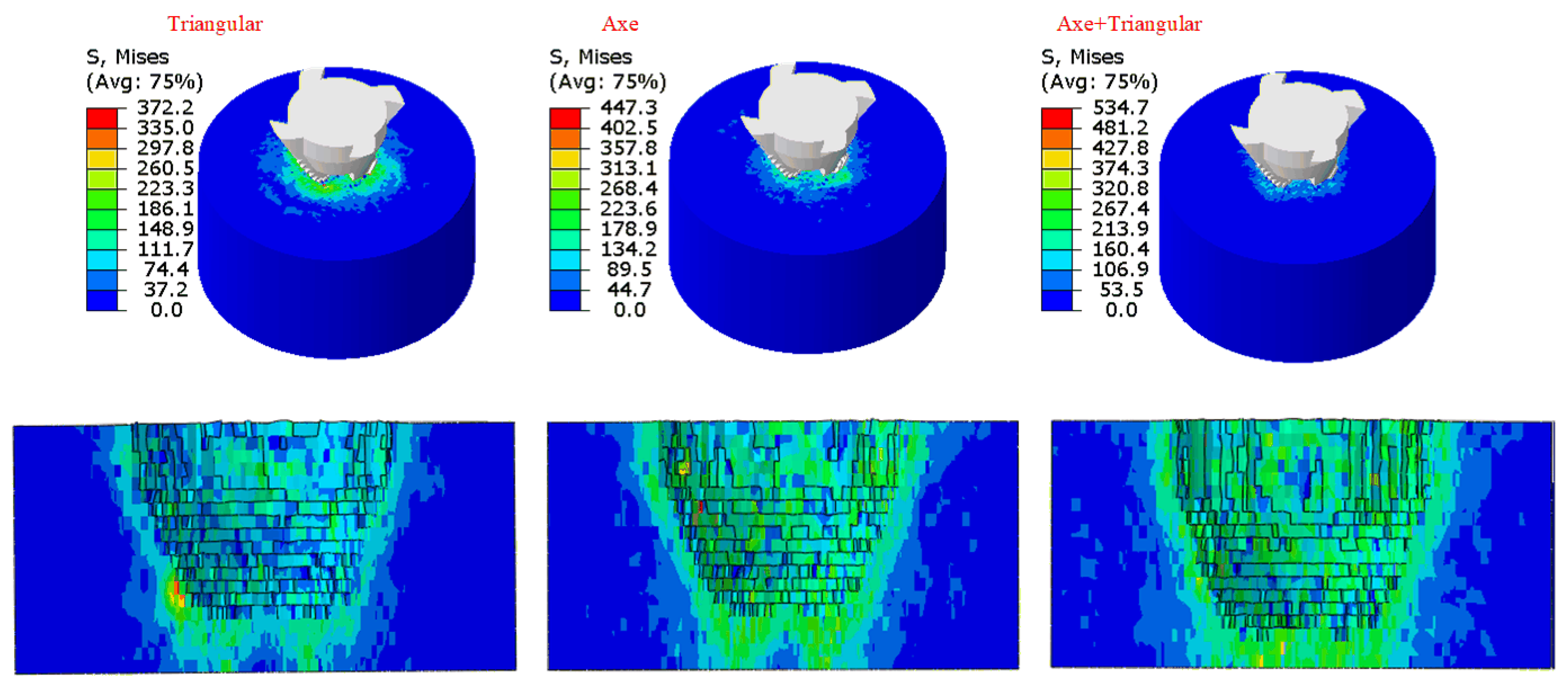
Due to the distinct shape variations between the axe, triangular prism, and cylindrical PDC cutters, the cylindrical PDC cutter predominantly crushes rocks in a shearing manner. On the other hand, the protruding ridge structure of the axe and triangular cutters exhibits a compressive effect during the rock-breaking process, thus enhancing its efficiency. The crushing effect of the axe cutter is notably more significant, raising the maximum stress on the rocks by 8.9% compared to the triangular prism cutter. This results in a stronger assault on the rocks, making it well-suited for front-row placement in drill bit cutter arrangements. Although the crushing effect of the triangular prism cutter does not match that of the axe cutter, its symmetric structure ensures stability during the cutting process, making it fit for the rear layout of the cutter. The rock-breaking performance of the cylindrical cutter is found to be the least efficient, suggesting its placement in the rear of the drill bit blade.
(2)
Different combinations of cutter arrangements have a significant impact on rock-breaking efficiency and stability. Therefore, it is necessary to make a rational selection of the arrangement scheme. When designing a mixed arrangement of cutters for a drill bit, it is recommended to place the axe cutters in the leading row of the blade while alternating the triangular prism and axe cutters in the rear row of the blade to fully utilize the benefits of the mixed arrangement of cutters in the drill bit.
(3)
The spacing between the cutters has a significant impact on the stability of the rock-breaking process. When designing a mixed arrangement of cutters for a drill bit, it is recommended to set the longitudinal distances between the leading row of axe cutters and the rear row of triangular prism cutters and axe cutters at 10 mm and 10.06 mm, respectively. The transverse distances between the centers of the rear row of triangular prism cutters and axe cutters and the centers of the leading row of axe cutters should be set at 7 mm to ensure that the mixed arrangement design maximizes drilling efficiency.
(4)
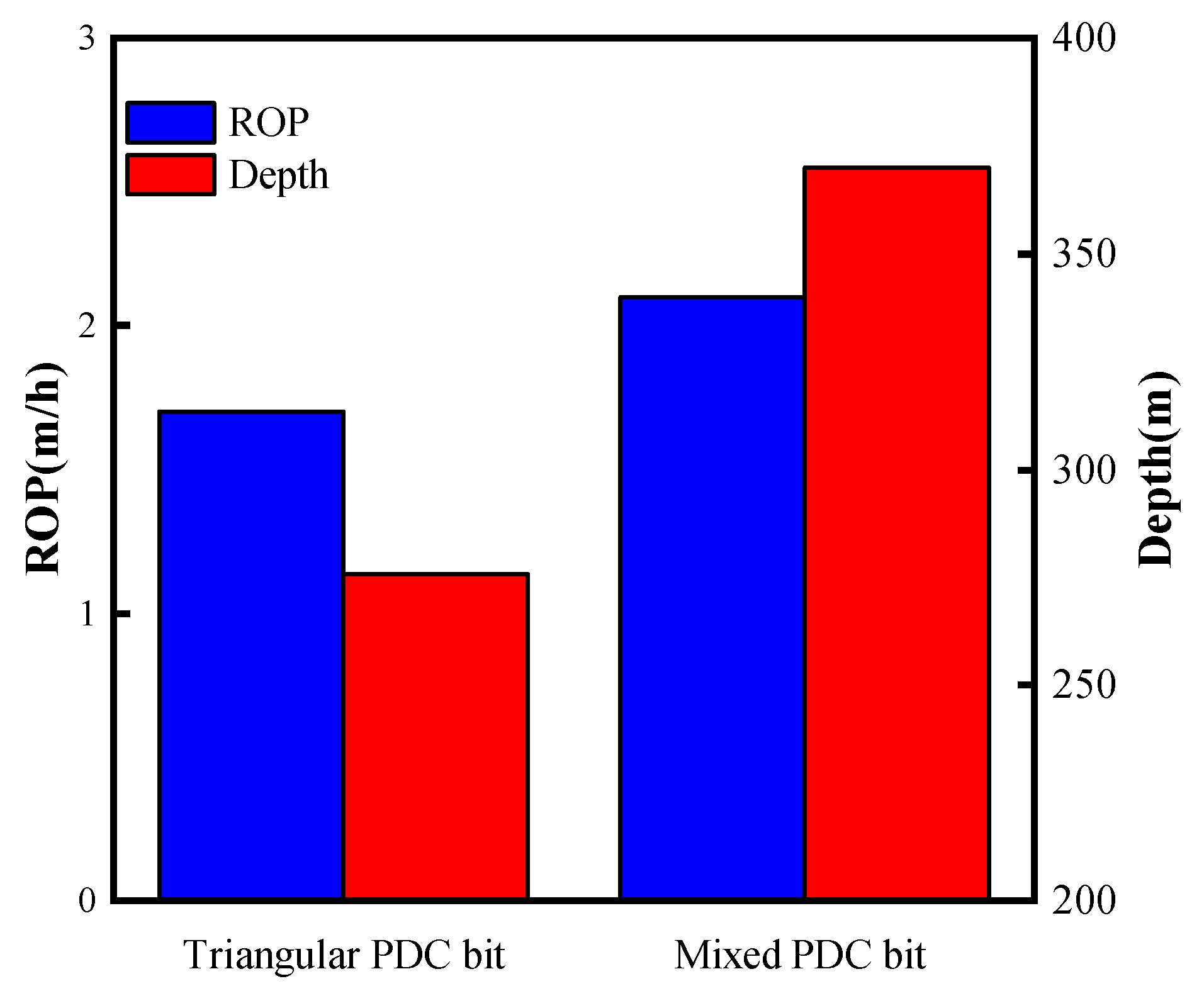
The numerical simulations and field drilling results indicate that compared to PDC drill bits with only axe or triangular prism cutters, the use of mixed arrangement cutter designs facilitates easier penetration of rocks, provides a more stable ROP during the rock-breaking process, and achieves higher efficiency. The utilization of PDC drill bits with mixed-arrangement cutters in complex drilling environments can effectively enhance the ROP and save drilling costs.
(5)
Although the numerical simulation method calculates the difference in the efficiency of the drill bit in breaking the rock in agreement with the field experiments, the calculation of the ROP of the drill bit is much different from reality. This is one of the limitations of numerical simulation of drill bit rock-breaking, but the obtained comparative simulation results are informative and can provide support for actual drilling.
The novelty of this thesis lies in the study of different cutter combinations and the optimization of the parameters of the cutter combinations using the Box-Behnken method to obtain the optimal cutter combinations and the related parameters, which provide data support for the field tests. Combined with the content of this paper, future research should focus on the optimized design of the structural parameters and shapes of the axe cutter and the triangular prism cutter, as well as the influence of different back rake angle combinations on the rock-breaking effect, in order to further improve the ROP of PDC bits and save drilling costs.

Author Contributions

Conceptualization, R.Y. and Z.W.; methodology, W.Z.; software, R.Y.; validation, S.H. and W.J.; formal analysis, R.Y.; investigation, W.Z.; resources, Z.W.; data curation, R.Y.; writing—original draft preparation, R.Y.; writing—review and editing, Z.W.; visualization, S.H.; supervision, Z.W.; project administration, R.Y.; funding acquisition, Z.W. All authors have read and agreed to the published version of the manuscript.

Funding

This research was funded by the Hundred-Talent Program (Grant No.Z16178/290088247), Xi’an Shiyou University for publication funding and Shanxi Provincial Key Project- International Collaboration Project of Science and Technology (Grant No.2022KW-10/221822021).

Conflicts of Interest

The authors declare no conflict of interest.

References

  1. Gao, D. Some research advances in well-engineering technology for unconventional hydrocarbon. Nat. Gas Ind. B 2022, 9, 41–50. [Google Scholar] [CrossRef]
  2. Zou, C.; Yang, Z.; He, D.; Wei, Y.; Li, J.; Jia, A.; Chen, J.; Zhao, Q.; Li, Y.; Li, J.; et al. Theory, technology, and prospects of conventional and unconventional natural gas. Pet. Explor. Dev. 2018, 45, 604–618. [Google Scholar] [CrossRef]
  3. Huang, H.; Zhao, B.; Wei, W.; Si, Z.; Huang, K. Effect of Cobalt Content on the Performance of Polycrystalline Diamond Compacts. Int. J. Refract. Met. Hard Mater. 2020, 92, 105312. [Google Scholar] [CrossRef]
  4. Shao, F.; Liu, W.; Gao, D.; Zhao, X. Development and Verification of Triple-Ridge-Shaped Cutter for PDC Bits. SPE J. 2022, 27, 3849–3863. [Google Scholar] [CrossRef]
  5. Cheng, Z.; Li, G.; Huang, Z.; Sheng, M.; Wu, X.; Yang, J. Analytical Modelling of Rock Cutting Force and Failure Surface in Linear Cutting Test by Single PDC Cutter. J. Pet. Sci. Eng. 2019, 177, 306–316. [Google Scholar] [CrossRef]
  6. Ma, Y.; Huang, Z.; Li, Q.; Zhou, Y.; Peng, S. Cutter Layout Optimization for Reduction of Lateral Force on PDC Bit Using Kriging and Particle Swarm Optimization Methods. J. Pet. Sci. Eng. 2018, 163, 359–370. [Google Scholar] [CrossRef]
  7. Xi, Y.; Wang, W.; Fan, L.; Zha, C.; Li, J.; Liu, G. Experimental and Numerical Investigations on Rock-Breaking Mechanism of Rotary Percussion Drilling with a Single PDC Cutter. J. Pet. Sci. Eng. 2022, 208, 109227. [Google Scholar] [CrossRef]
  8. Zhang, Z.; Zhao, D.; Zhao, Y.; Gao, K.; Zhang, C.; Lü, X. 3D Numerical Simulation Study of Rock Breaking of the Wavy PDC Cutter and Field Verification. J. Pet. Sci. Eng. 2021, 203, 108578. [Google Scholar] [CrossRef]
  9. Dong, Z.; Zhang, H.; Li, J.; Zhang, K.; Ou, Y.; Lu, Z.; Shi, J. A Method for Evaluating the Rock Breaking Efficiency of Cutters and Optimizing the PDC Cutter Profile—A Study of Igneous Rock Formations in Shunbei Oilfield. Energies 2022, 15, 6686. [Google Scholar] [CrossRef]
  10. Xiong, C.; Huang, Z.; Yang, R.; Sheng, M.; Shi, H.; Dai, X.; Wu, X.; Zhang, S. Comparative Analysis Cutting Characteristics of Stinger PDC Cutter and Conventional PDC Cutter. J. Pet. Sci. Eng. 2020, 189, 106792. [Google Scholar] [CrossRef]
  11. Ayop, A.Z.; Bahruddin, A.Z.; Maulianda, B.; Prakasan, A.; Dovletov, S.; Atdayev, E.; Rani, A.M.A.; Elraies, K.A.; Ganat, T.A.; Barati, R.; et al. Numerical Modeling on Drilling Fluid and Cutter Design Effect on Drilling Bit Cutter Thermal Wear and Breakdown. J. Pet. Explor. Prod. Technol. 2020, 10, 959–968. [Google Scholar] [CrossRef] [Green Version]
  12. Li, S.; Zhu, X.; Liang, K.; Deng, Y.; Liu, H. Numerical Simulation Study on Optimizing the Conical Cutter Bit to Break Deep Strata. Recent Pat. Eng. 2023, 18, 108578. [Google Scholar] [CrossRef]
  13. Crane, D.; Zhang, Y.; Douglas, C.; Song, H.; Gan, X.; Lin, Z.; Mueller, L.; Skoff, G.; Self, J.; Krough, B. Innovative PDC Cutter with Elongated Ridge Combines Shear and Crush Action to Improve PDC Bit Performance. In Proceedings of the SPE Middle East Oil & Gas Show and Conference, Manama, Kingdom of Bahrain, 6–9 March 2017; SPE: Manama, Kingdom of Bahrain, 2017; p. D031S014R004. [Google Scholar]
  14. Shao, F.; Liu, W.; Gao, D.; Ye, Y. Study on Rock-Breaking Mechanism of Axe-Shaped PDC Cutter. J. Pet. Sci. Eng. 2021, 205, 108922. [Google Scholar] [CrossRef]
  15. Yoan Mardiana, R.; Pasaribu, S. The Effects of PDC Cutter Geometries to the Drilling Dynamics in Various Geothermal Rocks: A Comprehensive Study Using Advanced Drilling Dynamics Simulation. IOP Conf. Ser. Earth Environ. Sci. 2022, 1014, 012006. [Google Scholar] [CrossRef]
  16. Kunshin, A.A.; Buslaev, G.V.; Reich, M.; Ulyanov, D.S.; Sidorkin, D.I. Numerical Simulation of Nonlinear Processes in the “Thruster—Downhole Motor—Bit” System While Extended Reach Well Drilling. Energies 2023, 16, 3759. [Google Scholar] [CrossRef]
  17. Wang, C.; Li, S.; Zhang, L. Evaluation of Rock Abrasiveness Class Based on the Wear Mechanisms of PDC Cutters. J. Pet. Sci. Eng. 2019, 174, 959–967. [Google Scholar] [CrossRef]
  18. Zeng, Y.; He, W.; Zhang, Z.; Shi, H.; Zhou, J.; Ding, S.; Ma, G. Rock-Breaking Performances of Innovative Triangular-Shaped Polycrystalline Diamond Compact Cutter. Rev. Sci. Instrum. 2021, 92, 035115. [Google Scholar] [CrossRef]
  19. Liu, J.; Zheng, H.; Kuang, Y.; Xie, H.; Qin, C. 3D Numerical Simulation of Rock Cutting of an Innovative Non-Planar Face PDC Cutter and Experimental Verification. Appl. Sci. 2019, 9, 4372. [Google Scholar] [CrossRef] [Green Version]
  20. Chen, C.; Yan, J.; Zou, Y.; Luo, H. Geometric Evolvement, Simulation, and Test of a Bionic Lateral PDC Reamer Bit Inspired by Capra Sibirica Horn. Appl. Bionics Biomech. 2022, 2022, 1–11. [Google Scholar] [CrossRef]
  21. Huang, Z.; Xie, D.; Xie, B.; Zhang, W.; Zhang, F.; He, L. Investigation of PDC Bit Failure Base on Stick-Slip Vibration Analysis of Drilling String System plus Drill Bit. J. Sound Vib. 2018, 417, 97–109. [Google Scholar] [CrossRef]
  22. Tian, K.; Detournay, E. Influence of PDC Bit Cutter Layout on Stick–Slip Vibrations of Deep Drilling Systems. J. Pet. Sci. Eng. 2021, 206, 109005. [Google Scholar] [CrossRef]
  23. Wang, Y.; Ni, H.; Wang, R.; Huang, B.; Liu, S.; Zhang, H. Numerical Simulation Research on Cutting Rock with a PDC Cutter Assisted by an Impact Force. Adv. Civ. Eng. 2022, 2022, 1–9. [Google Scholar] [CrossRef]
  24. Shao, F.; Liu, W.; Gao, D. Effects of the Chamfer and Materials on Performance of PDC Cutters. J. Pet. Sci. Eng. 2021, 205, 108887. [Google Scholar] [CrossRef]
  25. Zhu, X.; Dan, Z. Numerical Simulation of Rock Breaking by PDC Bit in Hot Dry Rocks. Nat. Gas Ind. B 2019, 6, 619–628. [Google Scholar] [CrossRef]
  26. Jamaludin, A.A.; Mehat, N.M.; Kamaruddin, S. Investigating the Effects of PDC Cutters Geometry on ROP Using the Taguchi Technique. J. Phys. Conf. Ser. 2017, 908, 012041. [Google Scholar] [CrossRef]
  27. Lam, K.Y.; Nélieu, S.; Benoit, P.; Passeport, E. Optimizing Constructed Wetlands for Safe Removal of Triclosan: A Box–Behnken Approach. Environ. Sci. Technol. 2020, 54, 225–234. [Google Scholar] [CrossRef]
  28. Silva, T.P.; Ferreira, A.N.; De Albuquerque, F.S.; De Almeida Barros, A.C.; Da Luz, J.M.R.; Gomes, F.S.; Pereira, H.J.V. Box–Behnken Experimental Design for the Optimization of Enzymatic Saccharification of Wheat Bran. Biomass Convers. Biorefinery 2022, 12, 5597–5604. [Google Scholar] [CrossRef]
  29. Angel, R.J.; Alvaro, M.; Nestola, F. 40 Years of Mineral Elasticity: A Critical Review and a New Parameterisation of Equations of State for Mantle Olivines and Diamond Inclusions. Phys. Chem. Miner. 2018, 45, 95–113. [Google Scholar] [CrossRef]
  30. Zhang, Y.; Wong, L.N.Y.; Chan, K.K. An Extended Grain-Based Model Accounting for Microstructures in Rock Deformation. J. Geophys. Res. Solid Earth 2019, 124, 125–148. [Google Scholar] [CrossRef]
  31. Peng, J.; Wong, L.N.Y.; Teh, C.I.; Li, Z. Modeling Micro-Cracking Behavior of Bukit Timah Granite Using Grain-Based Model. Rock Mech. Rock Eng. 2018, 51, 135–154. [Google Scholar] [CrossRef]
  32. Wang, L.; Bo, L.; Feng, L. Mechanical properties of heterogeneous rock under uniaxial compression based on mineral crystal model. Chin. J. Geotech. Eng. 2020, 42, 542–550. (In Chinese) [Google Scholar] [CrossRef]
  33. Zhang, Z.; Zhao, D.; Zhao, Y.; Zhou, Y.; Tang, Q.; Han, J. Simulation and Experimental Study on Temperature and Stress Field of Full-Sized PDC Bits in Rock Breaking Process. J. Pet. Sci. Eng. 2020, 186, 106679. [Google Scholar] [CrossRef]
  34. El-Sheikh, S.M.; Barhoum, A.; El-Sherbiny, S.; Morsy, F.; El-Midany, A.A.-H.; Rahier, H. Preparation of Superhydrophobic Nanocalcite Crystals Using Box–Behnken Design. Arab. J. Chem. 2019, 12, 1479–1486. [Google Scholar] [CrossRef] [Green Version]
  35. Xie, H.; Kuang, Y.; Qin, C. Finite element simulation and test of rock breaking by non-planar PDC cutters. J. Pet. Drill. Tech. 2019, 47, 69–73. [Google Scholar] [CrossRef]
Figure 1. Composition of heterogeneous granite [30].
Applsci 13 09133 g001
Figure 2. Rock model.
Applsci 13 09133 g002
Figure 3. Crack comparison.
Applsci 13 09133 g003
Figure 4. Comparison of stress-strain curves.
Applsci 13 09133 g004
Figure 5. PDC cutters with different shapes.
Applsci 13 09133 g005
Figure 6. Model simplification.
Applsci 13 09133 g006
Figure 7. Interaction between PDC cutters and rocks.
Applsci 13 09133 g007
Figure 8. Finite element model.
Applsci 13 09133 g008
Figure 9. Stress contour of the PDC cutter during the rock-breaking process.
Applsci 13 09133 g009
Figure 10. Different cutting forces with a cylindrical cutter in the front row.
Applsci 13 09133 g010
Figure 11. Axe cutter with different cutting forces in the front row.
Applsci 13 09133 g011
Figure 12. Different cutting forces with triangular prism cutters in the front row.
Applsci 13 09133 g012
Figure 13. Comparison of mechanical specific energy and mean cutting force. (a) The first set of schemes; (b) The second set of schemes; (c) The third set of schemes; (d) Comparison of best schemes.
Applsci 13 09133 g013
Figure 14. Contact stress contour: (a) Circular cutter in the front row; (b) Axe cutter in the front row; (c) Triangular-shaped cutter in the front row.
Applsci 13 09133 g014
Figure 15. The picture of Pareto.
Applsci 13 09133 g015
Figure 16. Contour map.
Applsci 13 09133 g016
Figure 17. Comparison of cutting forces before and after optimization.
Applsci 13 09133 g017
Figure 18. Rock-breaking comparison of drill bits before and after using an optimized cutter arrangement: (a) Finite element model; (b) Bit footage comparison.
Applsci 13 09133 g018
Figure 19. Drill cutting structure and finite element model.
Applsci 13 09133 g019
Figure 20. Bit numerical simulation verification: (a) The rate of penetration of a bit under constant WOB; (b) Bit reaction at constant WOB and ROP.
Applsci 13 09133 g020
Figure 21. Stress contour of a rock broken by a bit.
Applsci 13 09133 g021
Figure 22. Bit penetration rate and displacement comparison: (a) Bit footage comparison; (b) Comparison of instantaneous ROP.
Applsci 13 09133 g022
Figure 23. Effect of using a bit: (a) Before using the triangular prism bit; (b) After using the triangular prism bit.
Applsci 13 09133 g023
Figure 24. Effect of using a bit: (a) Before using the bit with a mixed arrangement cutter; (b) After using the bit with a mixed arrangement cutter.
Applsci 13 09133 g024
Figure 25. Data from the actual drilling process of the bit.
Applsci 13 09133 g025
Table 1. Material parameters of each component in granite.
ParametersQuartz MineralFeldspar MineralMica MineralOther Mineral
Volume content/(%)2449243
Density/(kg/m3)2650260030501650
Elastic/(GPa)51423324
Linear stiffness ratio1.11.31.73.7
Parallel modulus of elasticity51423324
Bonding stiffness ratio1.11.31.73.7
Tensile strength/(MPa)126 ± 16105 ± 1698 ± 1377 ± 9
Bonding strength/(MPa)196 ± 42162 ± 28146 ± 22105 ± 0
Friction angle/(°)19.522.417.323.7
Table 2. Seventeen sets of numerical simulation results.
Serial NumberFactorsCutting Force
Average Value E/kN
A/mmB/mmC/mmD/mm
115.012.512.09.516.7153
212.515.07.09.514.4970
312.512.512.012.018.6900
415.012.59.512.015.7510
510.010.09.59.514.5990
612.512.59.59.515.1812
715.012.59.57.014.7283
810.012.512.09.516.0326
915.012.57.09.514.6482
1010.012.59.57.013.7766
1115.010.09.59.515.4635
1212.510.07.09.514.6482
1312.512.59.59.515.1812
1410.012.57.09.514.2570
1512.512.57.07.013.2620
1612.512.59.59.515.1812
1712.515.012.09.518.2124
Table 3. The data for the ROP calculation.
Bit TypeMinimum Value of ROP/mm·s−1Maximum Value of ROP/mm·s−1ROP VarianceROP Standard Deviation
Bit with an axe cutter−52.8769.24388.1119.7
Bit with a triangular cutter−38.3955.15258.0916.06
Bit with a mixed set of cutters−19.9526.7783.599.14
Disclaimer/Publisher’s Note: The statements, opinions and data contained in all publications are solely those of the individual author(s) and contributor(s) and not of MDPI and/or the editor(s). MDPI and/or the editor(s) disclaim responsibility for any injury to people or property resulting from any ideas, methods, instructions or products referred to in the content.

