Abstract
In order to reduce the weight of optical elements in space remote sensors while increasing their stiffness, this paper takes an off-axis system secondary mirror as an example to design a square mirror with a size of 500 mm × 500 mm. The mirror adopts ultra-low expansion glass as the raw material. The paper proposed a lightweight form of gradual reinforcement and conducted the mirror assembly simulation analysis. The analysis results show that the weight of the lightweight mirror is 13.6 kg, and the surface density can reach 54.4 kg/m2. Under the circumstances of 1 g gravity and the temperature change of 15 °C~25 °C, the surface shape accuracy of the mirror assembly can reach 1/90λ (λ = 632.8 nm). Through the final testing, the first-order intrinsic frequency of the reflex mirror components is 167.8 Hz. The gap between the test results and the theoretical simulation results is less than 3%, which proves that the mirror assembly in the lightweight form of gradual reinforcement fully meets the index requirements and can provide a theoretical reference for the assembly of a mirror of similar size and type.
1. Introduction
The rapid development of space remote sensing technology has played a significant role in alarm reconnaissance, resource detection, and meteorological monitoring. With the steady improvement in scientific and technological levels, the demand for space remote sensing payload resolution is also gradually increasing. Large-aperture optical components with wide-field imaging capabilities have become the development direction of space remote sensing payload [1,2,3]. The off-axis optical system has the advantages of having fewer components, no block, a long focal length, a large field of view, a wide band, and a high modulation transfer function (MTF), which has become a trend in the development of long focal length and large field of view space remote sensing payloads in the world. However, its optical components are asymmetrical and need a lightweight design, bringing considerable difficulty to the design and processing [4]. Therefore, the development of space remote sensing loads using such optical systems has become an internationally recognized challenge, especially for the development of asymmetric square optical elements with a diameter of more than 400 mm, which has more significant technical difficulties and high risks [5].
The square mirror studied in this paper is the secondary mirror in the off-axis optical system and the farthest optical element in the system, which needs to withstand the harshest mechanical and thermal environment, and its surface shape accuracy directly affects the imaging quality of the entire remote sensing payload. As the farthest end of the system, the optical element needs to have a relatively light weight and high thermal dimensional stability when exposed to harsh thermal environments, and high stiffness is also required under harsh mechanical environments [6]. However, light weight, high stiffness, and thermal dimensional stability are usually contradictory, and a successful design seeks a balance so that its performance indicators meet the requirements.
This paper dives deep into the selection of raw material for mirrors, the design of the diameter-to-thickness ratio of mirror blanks, the optimization of the number of supporting points of mirror blanks, and the lightweight design of mirror blanks, providing detailed rationales with the primary goal of reducing weight, increasing stiffness, and ensuring surface shape accuracy. The engineering analysis of the designed mirror components is conducted by applying finite element simulation analysis technology. The design is further optimized according to the data results, and the obtained results meet the requirements of the design index.
2. Square Reflector Lightweight Design
Space optical components will be affected by mechanical shock, changes in ambient temperature, and atmospheric pressure during the satellite launch and in-orbit operation stages, which will lead to changes in the internal structure of the remote sensing payload, thus causing deviations in the face shape accuracy and position relationship of the optical components, and ultimately causing degradation in the imaging quality of the space remote sensing camera.
Therefore, the optical components are required to allow for a small amount of deformation, have high stability, as well as have a certain stress-release capability.
2.1. Mirrorr Structure Design
At present, the materials that can be used as space optical components in space mirror blanks are as follows [7]: fused silica glass (fused silicon), glass ceramic (Zerodur), silicon carbide (SiC), beryllium mirror (Be), and ultra-low expansion glass ULE (ultra-low expansion). Their material parameters are shown in Table 1.

Table 1.
Comparison of mirror material parameters.
It can be seen from Table 1 that the ultra-low expansion glass ULE has a low thermal expansion coefficient, and its absolute thermal expansion coefficient changes very little within 5 °C~35 °C. The material belongs to titanium dioxide–silicate glass, and its biggest feature is that it is easy to melt, which provides more possibilities for the lightweight structure of optical components [8,9,10].
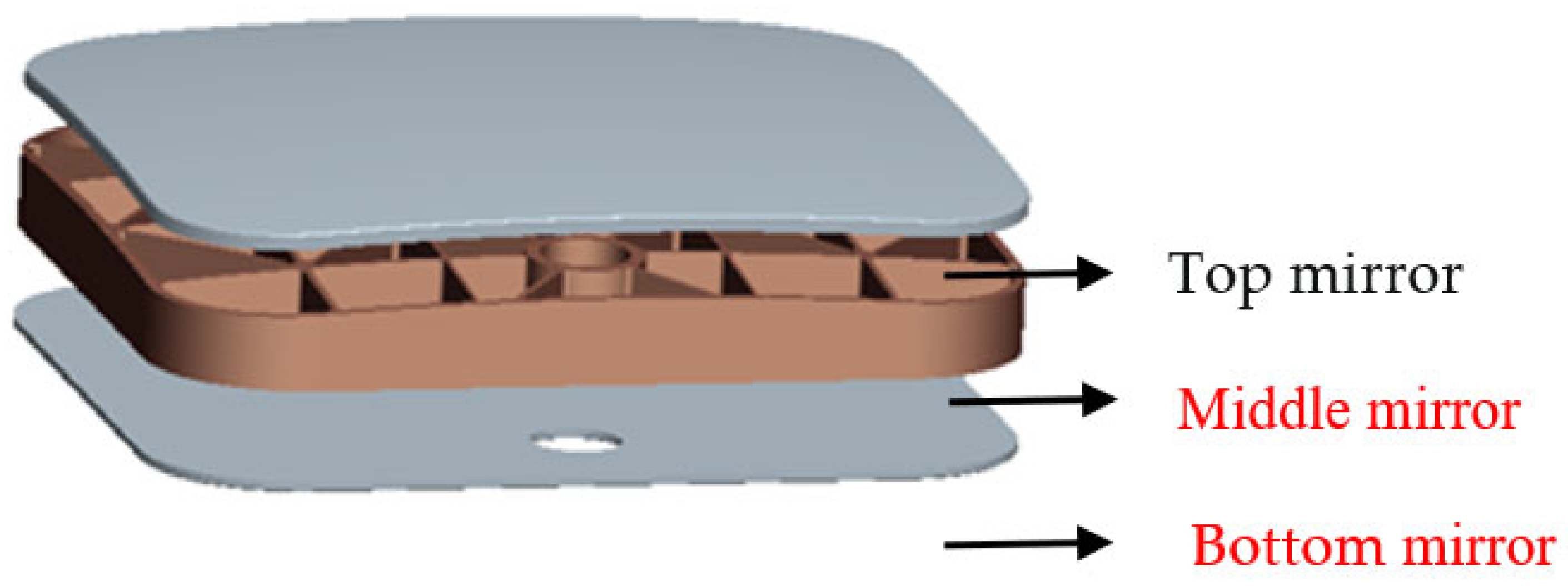
The basis for the design of the basic structure of the mirror is to ensure rigidity and surface accuracy, reduce weight, and have stress relief capabilities. According to the characteristics of the ULE glass material, which is easy to fuse, the mirror is designed to consist of three parts: the top mirror, middle mirror, and bottom mirror, which are combined by fusing, as shown in Figure 1.
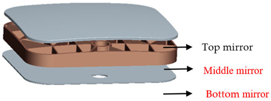
Figure 1.
Schematic diagram of mirror blank.
According to the surface structure of the optical element, the top mirror surface is an off-axis aspheric surface, which can be used as an interlayer for lightweight structural design, and the purpose of the bottom layer is to form a closed structure and improve the rigidity of the optical element.
2.2. Mirror Thickness Design
The size of the mirror includes the mirror size and thickness. This paper studies a square reflector whose size is 500 mm × 500 mm, and the diameter of the circumscribed circle is calculated to be 707 mm.
At present, for square reflectors, there is no general empirical formula to determine the thickness of the mirror. According to Roberts’s study regarding the relationship between diameter-to-thickness ratio dr (D/t) and self-weight deformation, an empirical formula can be given for initial calculation [11,12,13]. The formula is as follows:
In the formula, is the maximum self-weight deformation, is the material density, is the acceleration of gravity, is the radius of the disc, , and is the modulus of elasticity; is the thickness of the disc, and is the diameter of the disc. Substituting the circumcircle diameter Φ707 mm into the Formula (1), the thickness of the square reflector is calculated to be 78 mm, and this result can be used as an initial reference value.
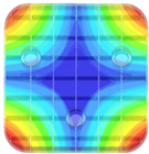
2.3. Design of Mirror Support Point Position
The stress point of the mirror is related to the support position, and the support position is designed according to the size and structure of the mirror. For mirrors with a caliber of 300 mm~700 mm, the number of support points, according to Hall [14], is calculated by the following formula:
In the formula, is the radius, is the thickness, is the material density, is the acceleration of gravity, is the elastic modulus, and is the maximum self-weight deformation.
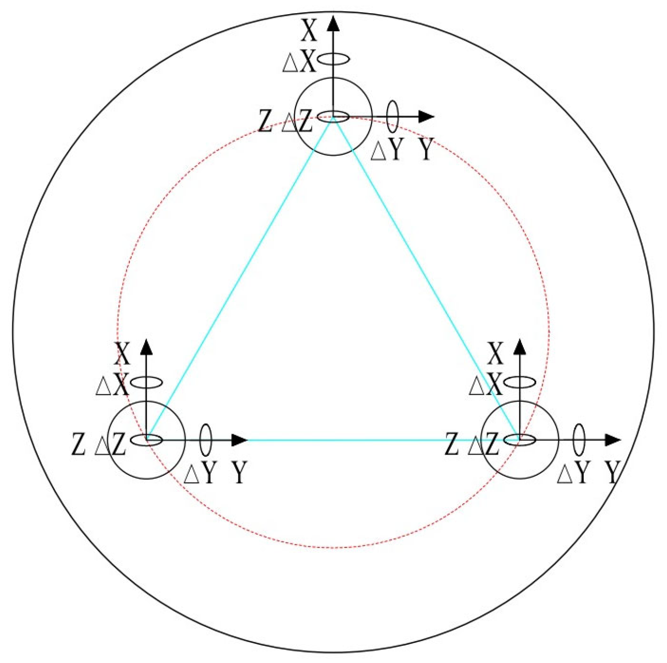
According to the requirement that the gravity deformation of the mirror should be less than λ/100 (λ = 632.8 nm), it is calculated by the Formula (2) that the number of support points of the Φ707 mm circular mirror N = 3.6. For a mirror in space, each support point has six degrees of freedom, that is, the translation along the X, Y, and Z directions and the rotation around the X, Y, and Z coordinate axes; if we restrict the six degrees of freedom entirely, the object can be fixed. For the space shape, by leveraging the stability of the triangle, the three-point support becomes suitable for application in small and medium-sized aperture (≤Φ500 mm) optical elements. Regarding large aperture (≥Φ500 mm) optical elements, three points or a multiple of three are also used to complete the design of the supporting system [15]. Given the number of support points is calculated as 3.6, we select the three-point support design. Shown in Figure 2.
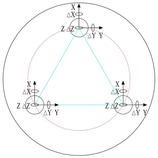
Figure 2.
Mirror gravity load.
2.4. Design of Mirror Support Point Position
- (1)
- Simulation of Sandwich Structures
The structure of the interlayer is the key part for releasing the stress, and it is also the core to adapt to the environment of large-span temperature change. The structure of the interlayer mainly includes the thickness of the outer ring, the width of the reinforcing rib, and its length and thickness.
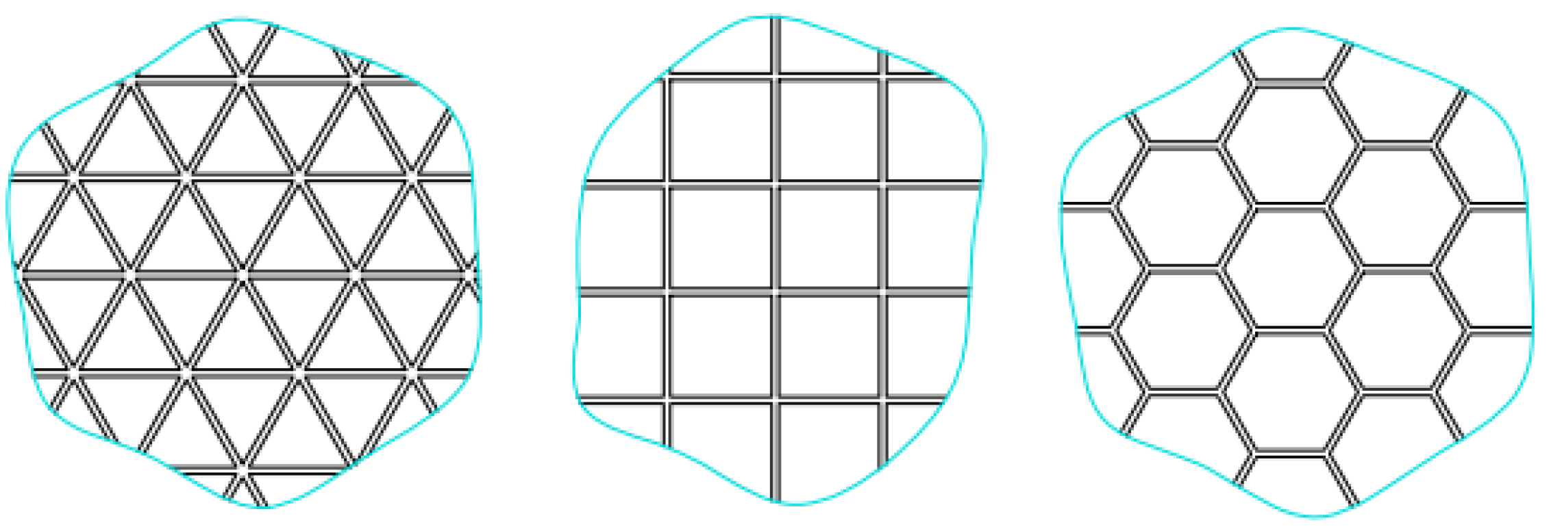
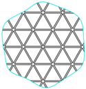
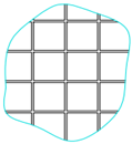
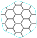
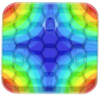
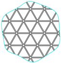
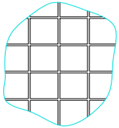
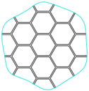
Common lightweight forms of sandwich structures include the triangular rib structure, square rib structure, and hexagonal rib structure [16] (see Figure 3). The structural form of the rib should consider not only the weight of the reflector but also the rigidity, manufacturing process, and processing process. Modal analysis can characterize the rigidity of the designed structure; the larger the modal value, the stronger the rigidity.
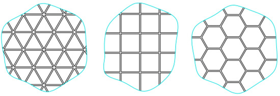
Figure 3.
Honeycomb grid structure form.
In this paper, aiming to obtain ribs with the same thickness (tentatively 4 mm) in the three structural forms, the three forms of mirrors were modeled and modal analysis was performed, as shown in Table 2, to obtain the weight and fundamental frequency of the three styles of mirrors. Among them, the mirror with a triangular rib structure has the lightest weight and the highest fundamental frequency, indicating that the triangular rib structure is more stable than the other two forms. Therefore, this paper chooses the triangular rib structure.
Table 2.
Comparative analysis of lightweight structure of sandwich.
The size of the ribs of the honeycomb structure determines the weight and rigidity of the sandwich structure. When the width and thickness are constant, the longer the ribs are, the worse the overall rigidity will be. In addition, under the action of gravity, the deformation of the mirror surface supported by the ribs is small, and the amount of deformation without rib support is so large that the lattice effect is obvious. At the same time, the removal amount of optical processing increases, and the difficulty increases. On the contrary, the use of smaller ribs can obtain better structural rigidity, but it will increase the weight of the mirror.
- (2)
- Stress simulation of mirrors
Compared with other structures, the sandwich structure has a certain stress-release ability. At the same time, the honeycomb structure with a triangular sandwich is also less stressed than other structures. The simulation results are shown in Table 3.
Table 3.
Stress simulation data.
- (3)
- Rib optimization design
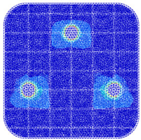
After it is determined that the triangular rib structure is used for the sandwich structure, and when the thickness and length of the mirror are also determined, the rib structure of the mirror with an aperture larger than Φ350 mm usually adopts an equal-width design. In this paper, through comparative analysis, the rib width of the reflector is optimized.
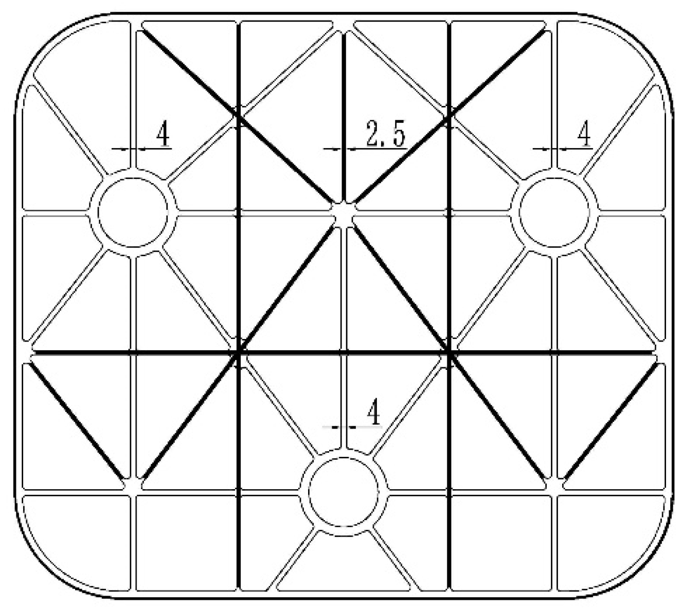
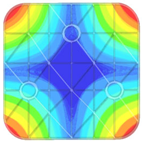
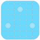
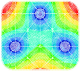
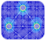
In order to further reduce the weight of the reflector, grouping is carried out according to the force-bearing path of the reflector, and a gradual reinforcing rib structure is proposed. That is, the length and thickness remain unchanged, and only the width of the reinforcing rib is changed, which is the width of the reinforcing rib of the supporting part of the reflector. It needs to be wider, and the parts with weak support can be narrower, as shown in Figure 4.
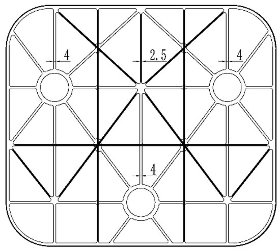
Figure 4.
Mirror stress layout.
Through the simulation, the change in the relationship between the weight of the reflector and the width of the rib is shown in Table 4, and the changing trend of the weight is simulated at the same time.
Table 4.
Width of rib, mirror mass, and modal.
It can be seen from the simulation results that when the width of the ribs changes within the range of 2.5 mm to 4 mm, the weight of the mirror does not increase much, but the mode becomes larger, indicating that the rigidity of the mirror becomes better.
3. Analysis and Evaluation of Simulation Results
Through the above simulation of the design of the reflector, the composition and structure of the reflector are preliminarily obtained. In view of the surface shape requirements of the remote sensing camera for the mirror assembly, the main factor affecting the surface shape of the mirror is the overall structure, including the support structure and materials of the mirror. The structure of the support system of the reflector, that is, the reflector assembly, is composed of a reflector, a biaxial arc flex joint, xx nesting, support legs, and a back support base, as shown in Figure 5 and Figure 6 and Table 5, providing the material properties of the individual components of the reflector assembly. In this way, the mechanical and thermal coupling simulation analysis of the overall structure of the preliminary design mirror is carried out to verify the rationality of the design.
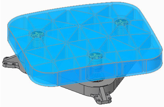
Figure 5.
Schematic diagram of mirror assembly simulation.
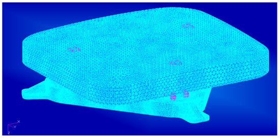
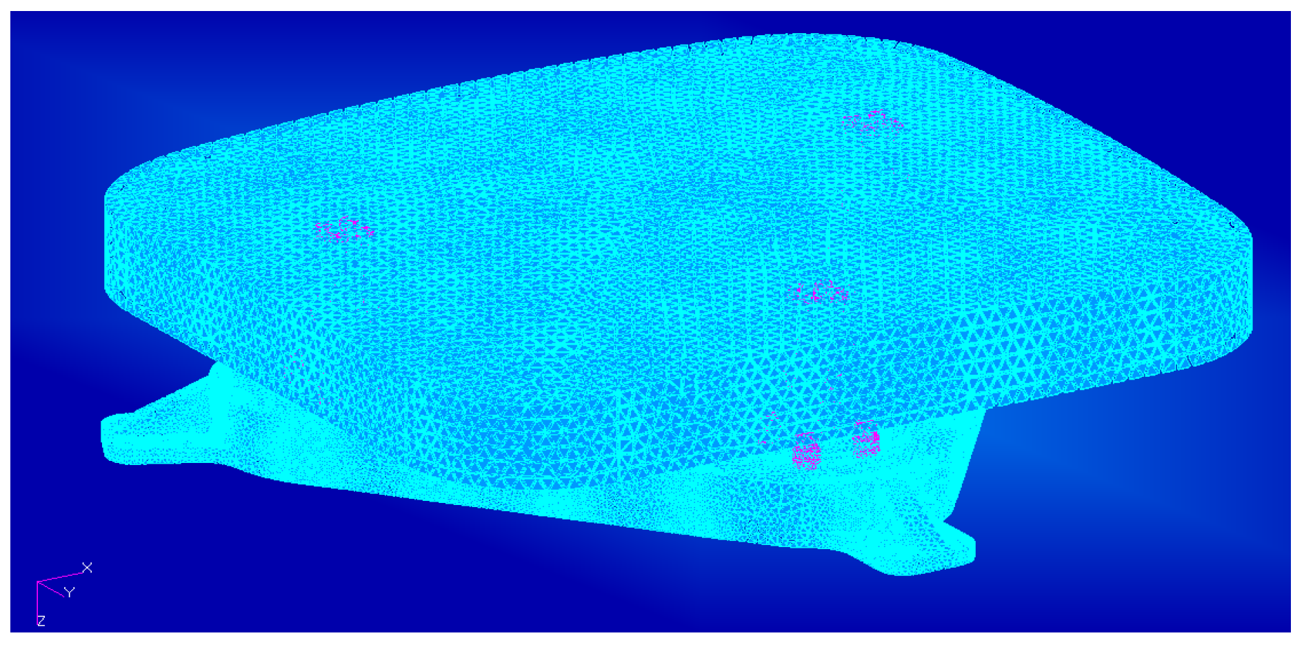
Figure 6.
Finite element model of mirror assembly.
Table 5.
Mirror material parameters.
The simulation analysis of the mirror component selects the tetrahedron mesh, which can divide any complex model quickly and automatically shape it, and it is easy to use the curvature and approximate size functions to automatically refine the local mesh in key areas, which can greatly save the time of mesh division.
3.1. Firmness Tests and Analysis
Modal analysis is an important parameter for the initial evaluation of the design rationality, and its analysis results can objectively reflect the mechanical characteristics of the structure and characterize the vibration response of the structure under mechanical loads.
Modal analysis theory is a technique used to determine the vibration characteristics of structures, through which mass frequency, vibration, and mode shape participation coefficients can be determined [17,18]. Modal analysis at the beginning of the design can prevent the structure from resonating or vibrating at a specific frequency, allowing designers to discover how the structure responds to different types of dynamic loads in the early stage and helping to estimate and solve control parameters in other dynamic analyses.
The fundamental frequency of the structure is known before the parts are processed, and then the design is optimized to ensure that it avoids forced vibration during launch and transportation to avoid resonance phenomena that could damage the structure.
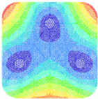
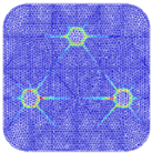
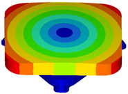
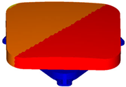
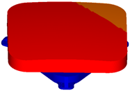
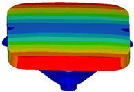
Through simulation, the first four order modes of the reflector assembly as a whole are shown below, and the analysis results are shown in Table 6. From the simulation results, it can be concluded that the first-order mode of the mirror assembly is 173.3 Hz, which is a high stiffness compared with the mirror assembly of the same size. Shown in Table 7.
Table 6.
Four vibration modes of the mirror assembly.
Table 7.
Results of analysis of the four modes of the mirror assembly.
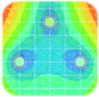
3.2. Static Analysis
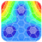
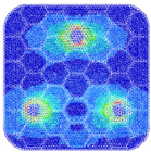
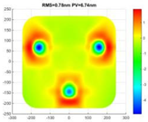
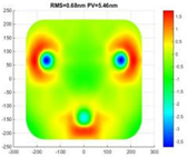
During the installation and adjustment of the space camera on the ground, the mirror will be affected by gravity, and it is necessary to analyze the degree of influence through simulation during the development process and take corresponding countermeasures [19,20]. The static analysis is to analyze the deformation of the reflector assembly under the action of gravity load and temperature load. According to the temperature range given by the thermal control analyst, the temperature condition of the reflector assembly is loaded. In this paper, the temperature load of the reflector assembly is 15 °C~25 °C. The axial and radial directions of the reflector assembly will show different characteristics due to the influence of temperature. It is also necessary to apply a 5 °C temperature gradient load to the mirror assembly axially and radially.
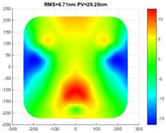
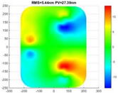
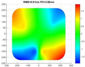
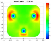
In this paper, the mirror assembly is loaded with a 1 g gravity load, forced displacement load, 15 °C~25 °C temperature load, 2 °C axial gradient load, and 2 °C radial gradient load. The results of the variation of the root mean square value of the reflector assembly shape in the spatial environment by simulation analysis are shown in Table 8.
Table 8.
RMS of mirror shape error under different environments.
After completing the simulation analysis and calculation of the 1 g gravity load, forced displacement (5 μm) load, 20 ± 5 °C temperature load, axial gradient 2 °C load, and radial gradient 2 °C load, the average value of the root mean square of the reflector assembly surface shape can be obtained by substituting the data results in Table 8 into Equation (3).
The calculated mean value of the root mean square of the mirror surface shape is 0.0156λ.
3.3. Vibration Test and System Evaluation
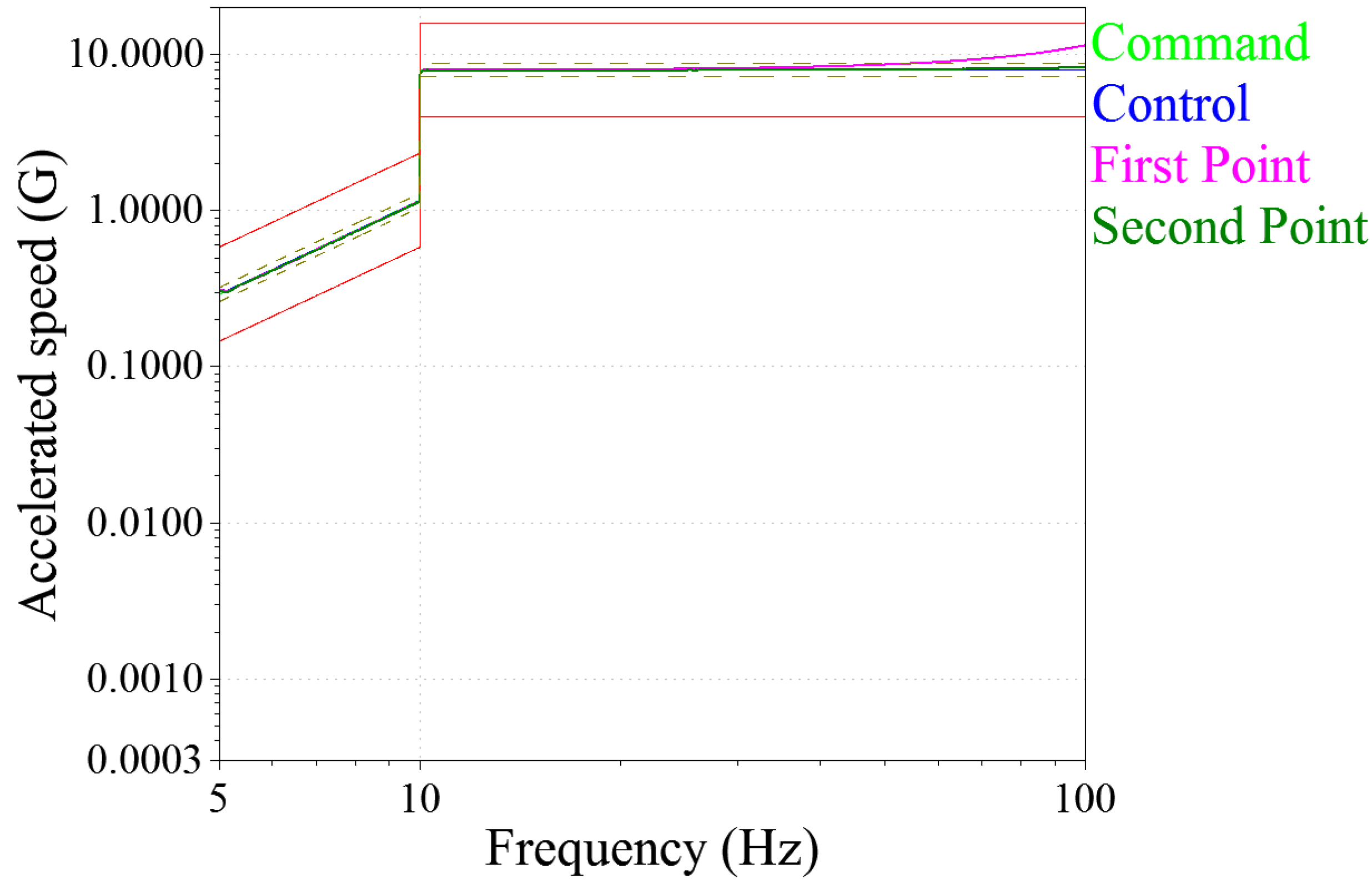
The space camera will experience a short-term mechanical environment during the launch phase [21]. In order to ensure the stability of the mirror assembly during the orbital operation phase, it is necessary to conduct mechanical tests on the components during the ground phase. The mechanical tests include a characteristic-level frequency sweep test, sinusoidal vibration test, and random vibration test to investigate whether the frequency drift of the mirror assembly occurs during the vibration process.
The test process is to first conduct a 0.2 g characteristic sine sweep test at 10~500 Hz, then an 8 g sine vibration test at 0~100 Hz, followed by a 0.2 g characteristic sine sweep test at 10~500 Hz, a 5.66 grms Random vibration test at 20~2000 Hz (time 2 min), and finally a 0.2 g characteristic level sine sweep test at 10~500 Hz.
In the mechanical test, two test points are pasted; one is located at the center of the reflector, and the other is in the center of the support base. The measurement point can reflect the changes in the test product in the mechanical test.
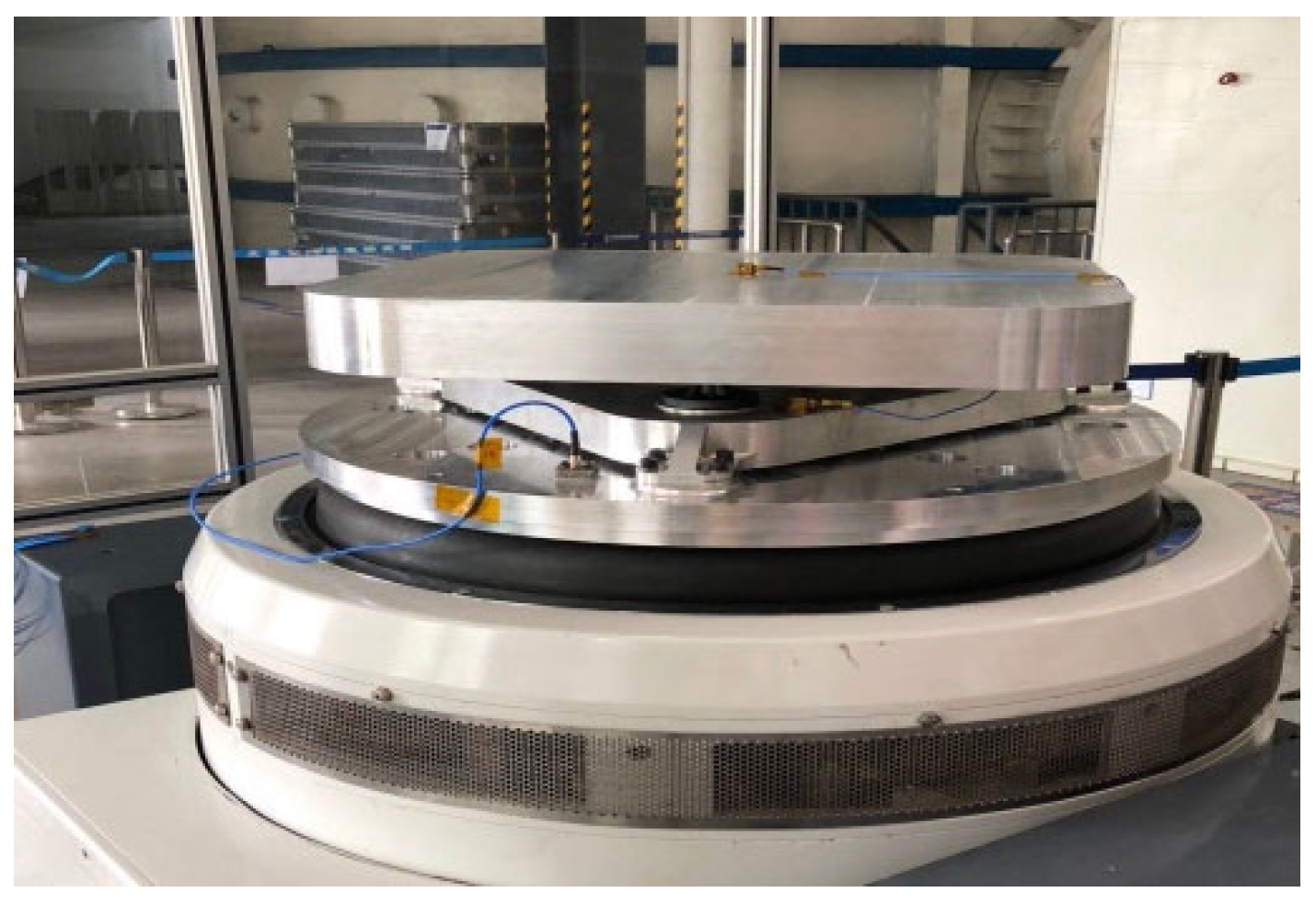
Two control points are pasted at the edge position of the vibration tooling to control the excitation of the mechanical test. After the vibration test, the test point values of the components before and after the test are compared to determine whether the designed components are qualified or not. As shown in Figure 7, the mechanical test diagram of the mirror assembly is shown. After the vibration tooling required for the mechanical test is connected to the test platform, the product under test is connected to the vibration tooling. Shown in Figure 8.

Figure 7.
Mechanical test diagram of mirror assembly.
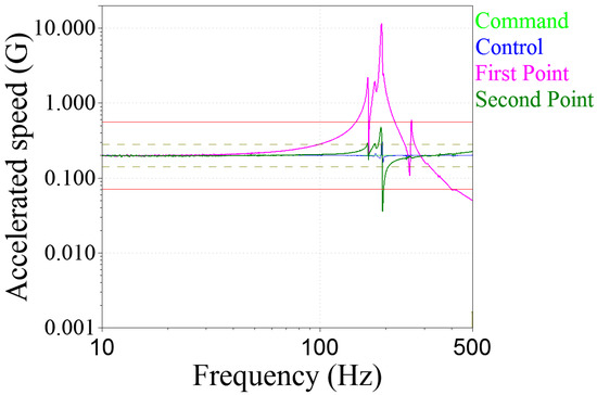
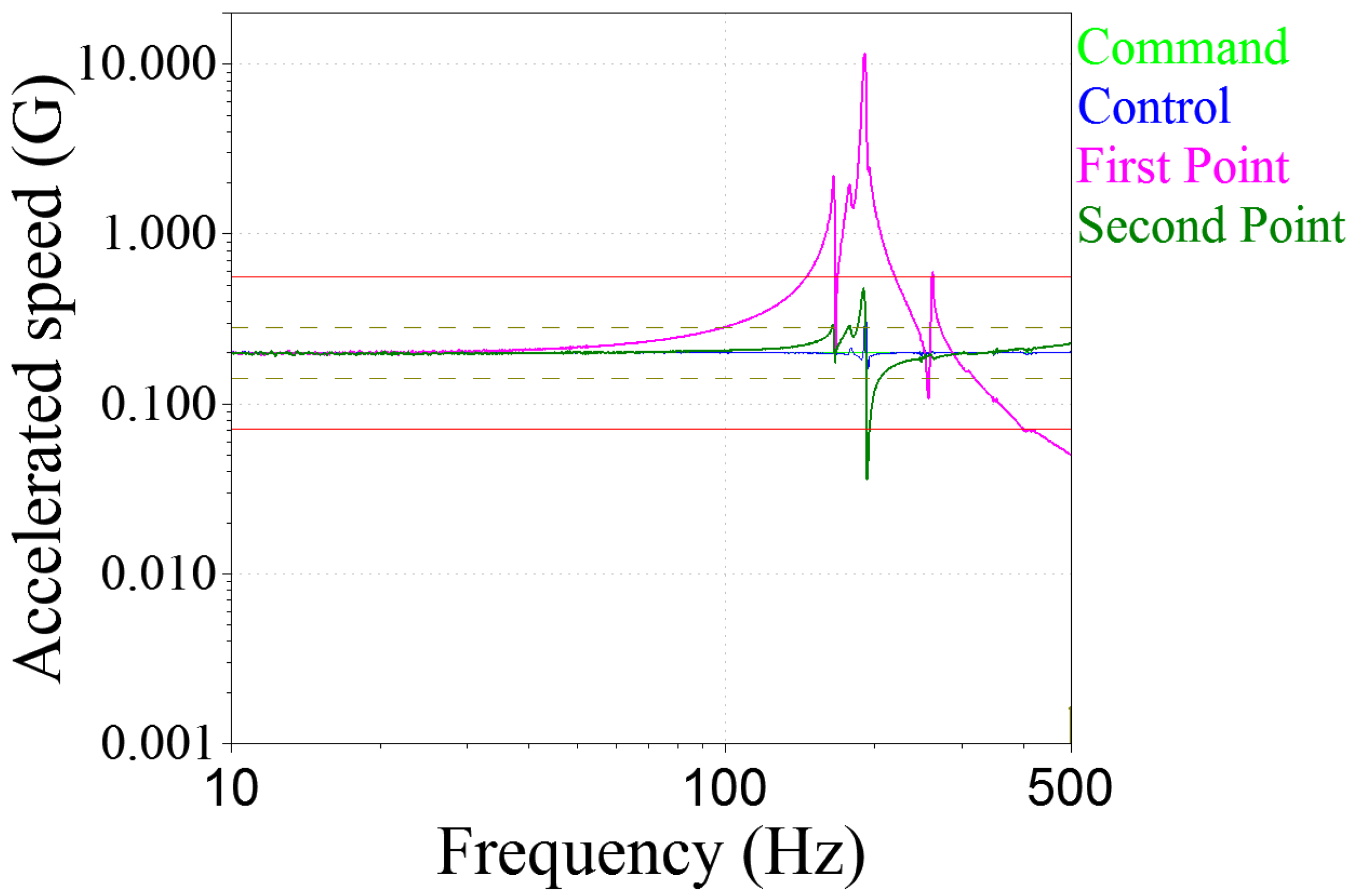
Figure 8.
Schematic diagram of the characteristic sweep frequency test curve of the mirror assembly.
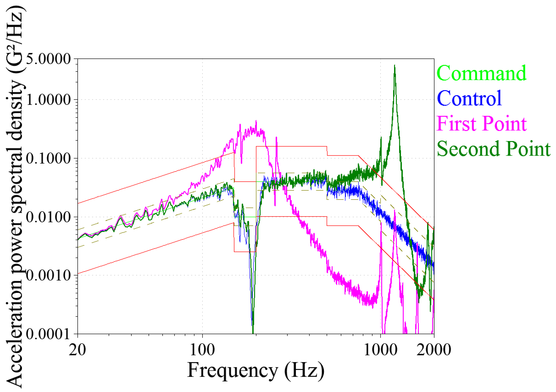
After testing, the first-order intrinsic frequency of the reflex mirror component is 167.8 Hz. The peak of the pink curve represents the value of the first-order frequency. The simulation calculation result is 173.3 Hz, and the real test result error is 5.5 Hz, which fully meets the analysis accuracy requirements and verifies the effectiveness of the finite element model. In the sine vibration test of 0~100 Hz, both measuring points are not large, as shown in Figure 9. In the random vibration test, the largest position of the response is the center of the reflector. The peak of the pink curve represents the maximum square acceleration of 16.91 g. As shown in Figure 10, the response was amplified by 2.97 times. The test results of this paper meet the environmental tests, indicating that the reflex is still highly stable after the mechanical test.
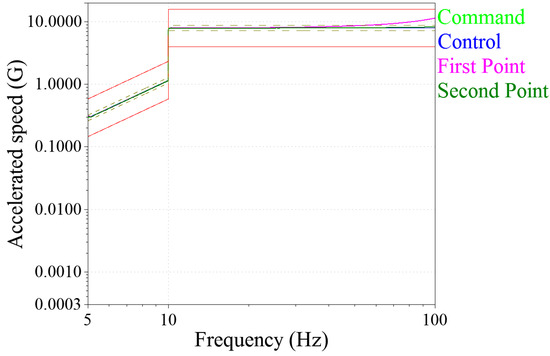
Figure 9.
Schematic diagram of sinusoidal vibration test curve of mirror assembly.
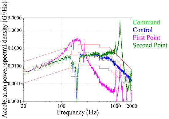
Figure 10.
Schematic diagram of random vibration test curve of mirror assembly.
4. Conclusions
In order to ensure the regular operation of a space remote sensor in a complex vacuum environment, the optical element must have good surface shape accuracy and withstand the harsh mechanical and thermal environment. Based on a square mirror in the off-axis system, this paper focuses on the lightweight design of the mirror blank. It designed the structure of the three-layer sandwich mirror with ultra-low expansion glass as the raw material. The triangular honeycomb structure was to reduce the weight with the premise of ensuring rigidity. The gradual reinforcement structure was proposed through comparative analysis. A simulation model similar to the actual optical component was established by applying the finite element method, and its statics and temperature field were analyzed and calculated. The results show that the surface shape accuracy reached 1/90λ under 1 g gravity and 1/500λ (λ= 632.8 nm) under 15 °C~25 °C temperature change. Finally, the mechanical test of the component shows that the first-order mode of the component was 167.8 Hz, which is close to the simulation calculation result of 173.3 Hz, with a gap of less than 3%, which further proves the reliability of the simulation analysis result. The components of the lightweight design of the square mirror studied in this paper have high static and dynamic stiffness and thermal dimensional stability. It shows that the design is reasonable, reliable, and has adaptability to the space environment. At the same time, the lightweight design and test verification method of the square mirror can provide a particular reference for the design and test of similar spatial mirrors and also provide technical guidance for the relevant research of professionals in the industry.
Author Contributions
Conceptualization, Z.Z. and S.D.; methodology, A.T. and B.L.; validation, Z.Z. and B.L.; data curation, X.D.; writing—original draft preparation, S.D., Z.Z. and A.T. All authors have read and agreed to the published version of the manuscript.
Funding
Basic Research (JCKY2020426B009); Shaanxi Provincial Science and Technology Department (2023KXJ-066).
Institutional Review Board Statement
Not applicable.
Informed Consent Statement
Not applicable.
Data Availability Statement
The data in this research are available from the corresponding author upon reasonable request.
Conflicts of Interest
The authors declare no conflict of interest.
References
- Stahl, H.P.; Postman, M.; Mosier, G.; Smith, W.S.; Blaurock, C.; Ha, K.; Stark, C.C. AMTD: Update of engineering specifications derived from science requirements for future UVOIR space telescopes. In Proceedings of the SPIE Astronomical Telescopes + Instrumentation, Montréal, QC, Canada, 22–27 June 2014. [Google Scholar]
- Miller, D.W.; de Weck, O.L.; Mosier, G.E. Framework for multidisciplinary integrated model-ing and analysis of space telescopes. In Proceedings of the Workshop on Integrated Modeling of Telescopes. International Society for Optics and Photonics, Lund, Sweden, 5–7 February 2002; pp. 1–18. [Google Scholar]
- Uebelhart, S.A. Non-Deterministic Design and Analysis of Parameterized Optical Structures during Conceptual Design. Ph.D. Thesis, Massachusetts Institute of Technology, Cambridge, MA, USA, 2006. [Google Scholar]
- Yan, C.; Xu, J.; Peng, Y. Stray light suppression of off-axis triple mirror space optical telescope systems. Opt. Precis. Eng. 2010, 18, 289–293. [Google Scholar]
- Krödel, M.R.; Hofbauer, P. Ultra-lightweighted HB-Cesic one-meter mirror demonstrator. In Proceedings of the SPIE Astronomical Telescopes + Instrumentation, San Diego, CA, USA, 27 June–2 July 2010. [Google Scholar]
- Zhang, X.J.; Li, Z.L.; Zhang, Z.Y. Space telescope aspherical mirror structure design based on SiC material. Infrared Laser Eng. 2007, 36, 577–582. (In Chinese) [Google Scholar]
- Bao, H.; Li, Z. Design of the strip SiC mirror supporting structure and lightweight. Opt. Tech. 2008, 34, 593–596. [Google Scholar]
- Stahl, H.P. Advanced Mirror Technology Development for Very Large Space Telescopes. In Proceedings of the 223rd American Astronomical Society Meeting, National Harbor, MD, USA, 5–9 January 2014. [Google Scholar]
- Egerman, R.; Matthews, G.; Wynn, J.; Kirk, C.; Havey, K. The Current and Future State-of-the-art Glass Optics. In Astro2010: The Astronomy and Astrophysics Decadal Survey; NASA: Washington, DC, USA, 2009. [Google Scholar]
- Stahl, H.P. Advanced Mirror Technology Development (AMTD) Project: Overview and Year Four Accomplishments. In Proceedings of the SPIE Astronomical Telescopes + Instrumentation, Edinburgh, UK, 26 June–1 July 2016. [Google Scholar]
- Bittner, H.; Erdmann, M.; Haberler, P. SOFIA Primary Mirror Assembly: Structural Properties and Optical Performance. In Proceedings of the Astronomical Telescopes and Instrumentation, Waikoloa, HI, USA, 22–23 August 2002; pp. 266–273. [Google Scholar]
- Parks, R.E.; Wortley, R.W.; Cannon, J.E. Engineering with lightweight mirrors. In Proceedings of the SPIE Astronomical Telescopes and Instrumentation for the 21st Century, Tucson, AZ, USA, 11–16 February 1990. [Google Scholar]
- Anderson, D.; Parks, R.E.; Hansen, Q.M.; Melugin, R. Gravity denections of lightweighted mirrors. In Proceedings of the International Conference on Advanced Technology Optical Telescopes, Tucson, AZ, USA, 11–13 March 1982. [Google Scholar]
- Friedman, E. Photonjcs Rules of Thumb; McGraw Hill: New York, NY, USA, 2003. [Google Scholar]
- Xu, H.; Guan, Y.J. Structural design of 1 m diameter space mirror component of space camera. Opt. Precis. Eng. 2013, 21, 1488–1495. [Google Scholar]
- Yang, J.W.; Huang, Q.L. Optimized design of structure parameters for large aperture mirrors. Chin. Space Sci. Technol. 2011, 31, 77–83. (In Chinese) [Google Scholar]
- Li, Z.L.; Xu, H.; Guan, Y.J. Structural design of 1.5 m mirror subassembly for space camera. Opt. Precis. Eng. 2015, 23, 1635–1641. (In Chinese) [Google Scholar]
- Zhang, B.W.; Wang, X.Y.; Zhao, Y. Development of space-based large aperture mirror support technology. Infrared Laser Eng. 2018, 47, 1113001. (In Chinese) [Google Scholar] [CrossRef]
- Wu, Q.; Yang, H.; Yang, J.; Chen, C.; Wang, Z.; Liu, H.; Gao, M. Design and analysis for primary mirror and its support of space camera. Opt. Tech. 2004, 30, 152–156. (In Chinese) [Google Scholar]
- Zhu, N. Research on the Design of the Supporting Structure of Lightweight Mirror. Ph.D. Thesis, University of Chinese Academy of Sciences, Chengdu, China, 2016. (In Chinese). [Google Scholar]
- Wang, K.J.; Dong, J.H. Composite support structure of large aperture mirror of space remote sensor. Opt. Precis. Eng. 2016, 24, 1719–1730. [Google Scholar] [CrossRef]


Disclaimer/Publisher’s Note: The statements, opinions and data contained in all publications are solely those of the individual author(s) and contributor(s) and not of MDPI and/or the editor(s). MDPI and/or the editor(s) disclaim responsibility for any injury to people or property resulting from any ideas, methods, instructions or products referred to in the content. |
© 2023 by the authors. Licensee MDPI, Basel, Switzerland. This article is an open access article distributed under the terms and conditions of the Creative Commons Attribution (CC BY) license (https://creativecommons.org/licenses/by/4.0/).