Abstract
Whether the subsea micro-drilling vehicle (SMDV) can perform its subsequent operations safely depends on the quality of the landing procedure. RecurDyn creates the SMDV dynamic model for this study. A model of the interaction between the SMDV and deep-sea sediment is built, and a simulation of the SMDV falling on the sea’s sediment substrate is developed. The water resistance is applied to the model by equivalent height replacement, and the in-situ soil data is measured with a triaxial undrained unconsolidated (UU) compression test and a load-sinkage experiment. When the landing surface is a flat sediment substrate, the release height is 5 m, the sinkage amount is 347 mm, and the center of mass’s impact acceleration is less than seven gravitational accelerations. Three states can occur when the vehicle lands on a sloped surface: stability, slip, and overturning. The risk of slipping and overturning is the least when the vehicle is landing on the ground in the forward direction, and the risk is equal when it lands on the ground in the backward and sideways directions. The ultimate overturning angle drops, and the final slip angle remains relatively constant as the vehicle’s release height increases. Our findings offer a theoretical foundation for the SMDV’s safe landing and the scientific formulation of rational release intervals.
1. Introduction
Numerous mineral resources, such as oil, flammable ice, polymetallic nodules, cobalt-rich crusts, and polymetallic sulfides, are found on the seafloor [1]. As terrestrial resources become increasingly scarce, the research and development of seabed mineral resource exploration and mining equipment have become a hot topic of discussion in this field [2,3]. In recent years, Germany, the United States, and Japan have conducted research and development initiatives to enable underwater tracked robots to be used in more challenging underwater terrains [4]. Jacobs University in Germany has developed Wally, a tracked robot sent to the seabed by an operational Remotely Operated Vehicle (ROV). The presence of a base station ROV that this robot uses for recharging increases its underwater operational time [5]. The Benthic Rover robot, developed by the Monterey Bay Aquarium Research Institute (MBARI) in the United States, has been designed to be independently deployed, with the capacity to be lowered to the seafloor from a support vessel via free diving [6]. The ABISMO ROV robot, developed in Japan, uses a launcher connected to the support ship. Electrical energy is provided to the vehicle through a high-powered photoelectric composite cable connected to the launcher [7]. Gao [8] designed a crawler robot that can adapt to deep-sea terrain, and the crawler is equipped to carry a platform that can extract multi-point sediments.
A new kind of underwater robot called the subsea micro-drilling vehicle (SMDV) combines a mobile crawler chassis with a coring tool to handle long-distance driving operations and multi-point seabed coring tasks. When the vehicle reaches its objective landing area, a launcher attached to the support ship will lower it to a predetermined height using a secondary armored umbilical line and let it fall, using its gravity for a hard landing. The SMDV is at risk from a hard landing because it could result in operational disruption from sinking or overturning and damage to the track chassis and other vital parts from the powerful force created upon contact with the substrate. Therefore, it is crucial for the practical deployment of the hard landing method to evaluate its impacts.
The focus of research into the dynamic effects of tracked machinery is primarily in the domain of military hardware. Hong [9] developed a finite element model of the airdrop equipment-airbag system to explore the connection between the initial velocity, tilt angle, and pitch angle of airdrop tank equipment at landing and the highest pressure of the airbag. Li [10] investigated the impact conditions of the tracked paratrooper fighting vehicle in airdrop and established the whole vehicle dynamics model and airdrop buffer model using multi-body dynamics and other modeling methods to study the dynamic load response characteristics of the whole tracked vehicle under impact conditions. Yang [11] employed the ADAMS Collision Process Dynamic Model to assess the anti-rollover capability of tank equipment under various attitude angles and impact velocities, synthesizing the effect of attitude angle and impact velocity on the stability of the tank equipment upon landing and contrasting the findings with the results of oblique impact experiments.
For marine equipment research, Du [12] designed an underwater landing robot in marine equipment and ran simulations of its motion, rotation, and straight-line dynamics. Yu [13] created a dynamic model of the benthic biological lander’s frame, did static and dynamic analyses, and used experimental data from sea trials to verify the frame’s impact resistance. Wang [14] created a footed robot with six legs and constructed coordinate systems for each. He then conducted dynamics simulation experiments on the underwater buffer landing process using a joint simulation of Matlab and ADAMS, which was crucial for the robot’s cable-free diving. Most researchers have focused on the kinematic performance of the driving process of deep-sea machinery of the crawler type. Hong [15] proposed a three-dimensional dynamic model of a submarine-tracked vehicle traveling on cohesive soil in 2002 and simplified the tracked vehicle to a single rigid body with six degrees of freedom to solve for its pressure-sink and shear displacement characteristics. Zhang [16] entered the soil characteristics of the simulated deep-sea soil into the multi-body model of the subsea mining collector after conducting pressure subsidence and shear displacement experiments on the soil. The kinetic software RecurDyn models the interaction between the deep-sea mining vehicle and the seabed. Dai [17] integrated the role of hydrodynamic forces on the collector on this basis. It conducted underwater experiments on the laboratory mining vehicle model to verify the dynamics model’s feasibility. After multi-body dynamics modeling of the crawler deep-sea mining vehicle, Su [18] demonstrated the consistency between straight-line travel and simulation through sea trials, which provided the basis for subsequent functions such as turning, climbing, and overcoming obstacles.
There are fewer studies on the landing impact of tracked subsea equipment. Xu [19] established a 3D model of the mining vehicle in SolidWorks in 2004 and performed a landing simulation in ADAMS. Shiosawa [20] considered the hydrodynamic and sandy substrate for a tracked ROV, established a mathematical model of its dynamics, and conducted walking experiments in both a water tank and the sea. The results showed that the calculated and experimental results had a high agreement. Guo [21] analyzed the varying conditions of the full ocean depth landing vehicle, contrasted the effect of the vehicle on rock and mud surfaces, refined and enhanced its structure, and conducted numerical simulation analysis. These analyses resulted in a noteworthy decrease in stress concentration regions, enhancing the vehicle’s landing security.
The study of the dynamic response characteristics during the walking of land-based tracked equipment and subsea non-tracked landers has made significant progress. However, the analysis of the hard landing dynamics of subsea-tracked equipment is still in its infancy. In the crawler multi-body dynamics modeling, the previous multi-body dynamics modeling ignores water resistance and the influence of sediment soil properties on its interaction. It cannot simulate the real-world environment. In addition, most multi-body dynamics modeling approaches cannot evaluate tracked equipment’s impact acceleration and overall stability. This study uses multi-body dynamics simulation software to build a system dynamics model of the AMDV, which is the subject of the study. The grounding process is then dynamically analyzed to see how different heights and slopes affect the vehicle’s response. This paper offers a theoretical framework for the SMDV’s safe deployment and process control.
2. Landing Process and Establishment of MBD Model
2.1. SMDV Landing Process
The SMDV is typically transported to the operation area by the support ship, and the launcher carrying the vehicle is lifted to a specific sea depth by a first-class armored umbilical cable. The vehicle is then released from the launcher to land in free fall by its gravity and transmit power and data to the launcher via the gravity-free cable, as depicted in Figure 1. Due to the influence of complex ocean conditions, support ship and launcher sway, and seafloor topography, the SMDV is released at a certain height above the seafloor in order to prevent damage. After landing on the substrate, the SMDV utilizes its crawler travel mechanism to traverse the seafloor in a specific region to conduct multipoint geological coring operations.
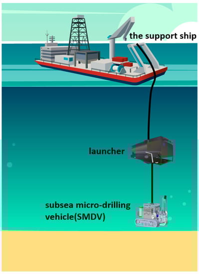
Figure 1.
SMDV landing process.
2.2. Establishment of the Multi-Body Dynamic Model
The SMDV primarily consists of a core extraction mechanism, crawler travel mechanism, power and control device, and other components, as shown in Figure 2; its structural parameters are shown in Table 1. This paper uses the MBD analysis software RecurDyn to model and analyze the SMDV, which adopts the theory of relative coordinate system equations and a fully recursive algorithm, and is suitable for solving large-scale and complex contact dynamics problems.
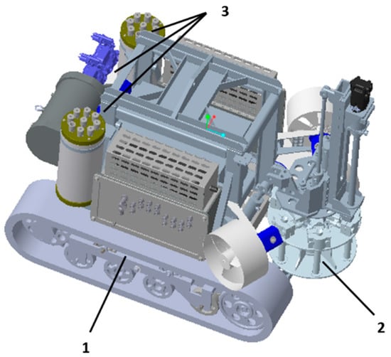
Figure 2.
Three-dimensional model of SMDV. 1—crawler travel mechanism, 2—core extraction mechanism, 3—power and control device.

Table 1.
Structure parameters of SMDV.
To begin, construct the 3D model of the SMDV in ProE, import it into RecurDyn/TrackLM on an equal scale, and define the constraint relationship between each structure of the SMDV, in which the complex structure of the undercarriage wheel system and the track is constructed through CAD_Link/Sprocket/Flange for the simulation of the interaction between the track and the deep-sea sediment.
2.3. Establishment of the Multi-Body Dynamic Model
RecurDyn/Track_LM offers mechanical substrate models for sand, heavy clay, and sandy loam soils in the track–ground contact relationship. The implementation principle is based on the empirical indentation-subsidence equation proposed by Bekker [22] for the experimental analysis of many soils (1) and the relationship between shear stress and shear displacement proposed by Wong [23] for brittle soils (2):
where p is the ground pressure between the track and the soil (kPa), kc is the soil cohesive deformation modulus (kN/mn + 1), kϕ is the frictional deformation modulus (kN/mn + 2), b is the length of the short side of the contact plate (mm), z is the sinkage amount (mm), and n is the sinkage index.
In Equation (2), τ represents shear stress, c represents cohesion, σs represents normal stress, ψ represents the angle of internal friction, j represents shear displacement, Kω represents shear deformation modulus, and Kr represents the ratio of residual shear stress to maximal shear stress. In order to obtain the model parameters, the pressure-sinkage experiment (Figure 3) and triaxial undrained unconsolidated (UU) compression test (Figure 4) were conducted using deep-sea sediment samples at a depth of 2000 m in a sea area. The following experimental analyses were performed on the soil in this area according to the experimental method of measurement of deep-sea sediments by Wu [24] and Dai [25].
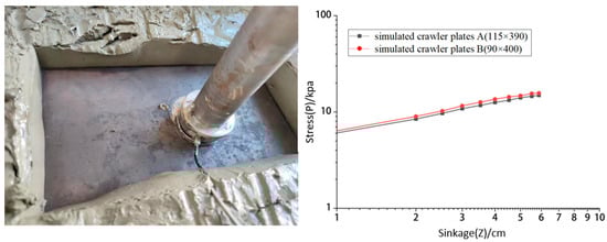
Figure 3.
The pressure-sinkage experiment and the double logarithmic curves of compressive stress-sinkage.
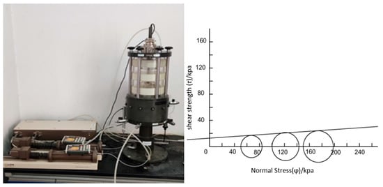
Figure 4.
The triaxial undrained unconsolidated (UU) compression tests and the Stress Molar Circle.
According to the actual aspect ratio of the SMDV, simulated crawler plates A and B (115 mm × 390 mm and 90 mm × 400 mm) were selected for data analysis. The compressive stress and sinkage coordinates of simulated crawler plate A and B were simultaneously taken logarithmically to obtain their corresponding double logarithmic curves of compressive stress-sinkage, as shown in Figure 3.
During test settings with a surrounding pressure of 50 kPa, 100 kPa, and 150 kPa, sediment specimens were subjected to triaxial undrained unconsolidated (UU) compression tests. Measurement of the shear strength of sediments under different environmental pressures and the relationship between the principal stress difference and axial strain could be determined. To calculate the sediment sample’s internal friction angle and cohesion parameters, it is necessary to plot the molar stress circle of the sample, establish a right-angle coordinate system with the normal stress as the horizontal coordinate and the shear strength as the vertical coordinate, plot the stress results under each level of enclosing pressure on the coordinate axis for the radius, and plot the envelope of the stress circle under each level of enclosing pressure (Figure 4). The longitudinal coordinate of the point of intersection with the y-axis represents the specimen’s cohesive force.
In the pressure-sinkage experiment, when the sinkage is 1 cm, curve A and B intercepts are 6.3 kPa and 6.0 kPa, respectively. The conversions in meters are 73.34 kPa and 67.63 kPa, respectively. The experimental data obtained in the triaxial compression test can calculate the internal friction angle of the deep-sea sediment to be about 4° and the cohesive force c to be about 12.715 kpa. The deformation index n is the average of the slope of both 0.53. The mechanical properties of the deep-sea sediment soil were derived, as shown in Table 2.
Table 2.
Mechanical parameters of the deep-sea sediment soil.
2.4. Analysis of the Effect of Landing Water Resistance
The RecurDyn software only accounted for the free-fall height of a multi-body system subject to the force of gravity without considering other potential factors that could impact the descent. During the landing process of the SMDV, the combined effect of water resistance and buoyancy has a particular effect on the acceleration and landing impact of the SMDV when it lands on the substrate, so it is necessary to analyze and calculate the motion of the SMDV when it lands on the substrate. Considering the water resistance and buoyancy on the SMDV [26,27], the kinetic equation of the SMDV landing process is given by:
The specific parameters in the formula are represented by Table 3, and this differential equation can solve the landing speed corresponding to a certain release height according to the initial conditions of the SMDV’s release fall.
Table 3.
Hydrodynamic coefficient values.
When the track lands on the substrate, the landing speed is crucial in SMDV fall impact. The same landing velocity in free fall, referred to as the equivalent release height in this paper, can be obtained by applying the principle of equal fall velocity and solving the underwater fall velocity using the formula above. Figure 5 illustrates the relationship between the SMDV’s landing velocity and the release fall height. The SMDV’s landing speed is substantially slower than the free-fall speed, as indicated in the figure, and this difference becomes more and more noticeable as the release height increases due to buoyancy, particularly water resistance. Due to the influence of water resistance, the release height has a decreasingly significant impact on the landing velocity. When the release height reaches 4 m, the SMDV experiences zero vertical acceleration and reaches its maximum and stable falling velocity. The simulation software can apply this method to simulate the effect of hydrodynamic action on SMDV.
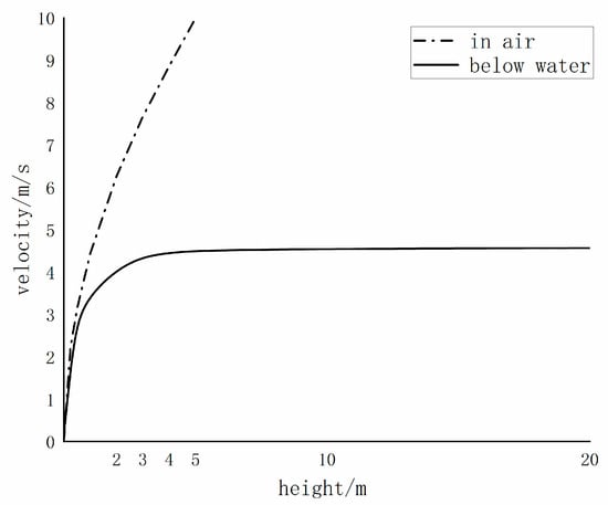
Figure 5.
Relationship between landing speed and release fall height (in air/below water).
3. Simulation Analysis of Landing Dynamics
3.1. SMDV Landing Response Analysis
This study examines the center of mass displacement and center of mass acceleration response of the SMDV to evaluate its security. The center-of-mass displacement of the SMDV corresponds to the sinkage of its impact on the subsea substrate, which can be used to analyze whether it affects subsequent driving. The center-of-mass acceleration of the SMDV can be used to analyze the impact resistance of the instrumentation in the SMDV, and Figure 6 depicts the flowchart of the simulation method. Regarding a vehicle lowered from a height of 2 m onto a flat substrate surface, the simulation analysis of the substrate impact of the SMDV is performed, and the results are depicted in Figure 7, Figure 8 and Figure 9.
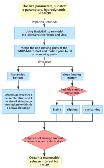
Figure 6.
Flow chart of the simulation method.
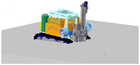
Figure 7.
SMDV Landing sinking process.
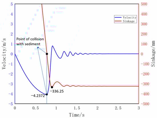
Figure 8.
Simulation curve of SMDV mass velocity and sinkage.
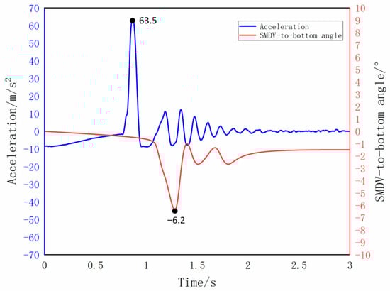
Figure 9.
Simulation curve of SMDV-to-substrate angle and mass acceleration.
The process of SMDV landing on the subsea substrate can be divided into three phases based on the changes in velocity, acceleration, and the angle between the SMDV and the subsea substrate. The first stage occurred from 0–1 seconds when the SMDV center-of-mass displacement, velocity, and acceleration experienced their respective maxima. The maxima of the angle between the SMDV and the substrate surface occurred from 0–1.5 s: the maximum subsidence value of 336.28 mm, the maximum velocity of about 4.24 m/s, the maximum acceleration of 63.5 m/s2 appeared at about 0.7 s, and the maximum angle of clamping of 6.2° appeared at about 1.3 s. The second stage occurred from 1–2 s, and the SMDV’s center of mass displacement, velocity, and acceleration oscillated and altered before stabilizing after approximately eight cycles. The angle between the SMDV and the substrate surface stabilized after three cycles. After two seconds, the displacement, velocity, and acceleration of the SMDV’s center of mass and the angle between the SMDV and the substrate surface were essentially stable, with a subsidence value of 325.07 mm, and the velocity and acceleration were 0. Since the SMDV’s center of mass was in front of the SMDV, the body of the SMDV was slightly inclined forward when it was stabilized, forming an angle of −1.5° with the substrate surface.
To observe the effect of the release height of the SMDV on its subsidence and impact acceleration, simulation experiments of the SMDV at 2–5 m release height were conducted in RecurDyn software, which was set up with the equivalent height of the free-fall equivalent to obtain the subsidence (stable value) and impact acceleration (maximal value) of the SMDV at different release heights, as illustrated in Figure 10. As shown in the graph, as the SMDV’s release height increases, its lowering volume and impact acceleration increase approximately linearly, consistent with the upward trend of the SMDV’s landing speed.
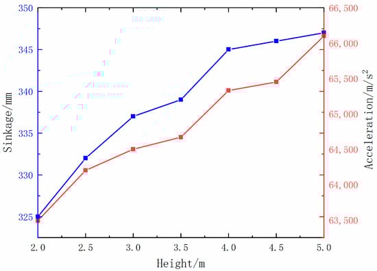
Figure 10.
Influence of SMDV release height on sinkage volume and impact acceleration.
In general, when the landing sinkage of the SMDV does not exceed the distance between the top of the drive wheel and the substrate surface of the track (350 mm for SMDV), the tracked traveling mechanism can travel after landing. The simulation results show that when the release height is 5 m, the sinkage amount of the SMDV is close to the critical value. In order to prevent falling too deep into the sediment, the SMDV’s release height must be controlled within 5 m. The SMDV is outfitted with electronic components for sensing and control, and the acceleration response of the general instrumentation must not exceed ten gravitational accelerations. According to the simulation results, the SMDV’s impact acceleration at a release height of 5 m is approximately 6.6 gravitational accelerations, which does not damage electronic components. Notably, these simulations are founded on the sediment substrate of a particular target sea area. The harder the sediment, the smaller the quantity of SMDV subsidence and the greater the distance from the critical value. However, the greater the impact acceleration of the SMDV, the greater the risk of electronic component damage. If the sediment is softer, the impact acceleration of the SMDV will be reduced, and the electronic components will be safer; however, the sinkage of the SMDV will increase, and the risk of sinking into the sediment will increase. On the one hand, there is reasonable selection of the SMDV release fall height according to the SMDV service sea substrate mechanical parameters. On the other hand, we should optimize the structural design of the SMDV based on the mechanical properties of the seabed in the service area and increase the width of the track as necessary to avoid potential safety hazards.
3.2. Simulation Analysis of SMDV Slope Landing Substrate
The complex topographic conditions of the deep seabed generally require SMDV to be able to land and travel on an inclined substrate surface. RecurDyn(V9R4) software was used to create a sloping surface with angles ranging from 0 to 45 degrees, and the SMDV was evaluated for its ability to anchor on the seabed under various release heights of 2–5 m. The forward, backward, and lateral landing modes of the SMDV are taken into account in the simulation experiments, as shown in Figure 11, because the different orientations of the SMDV landing change the spatial relationship of its center of mass concerning the inclined surface and the attitude response of the SMDV after landing.
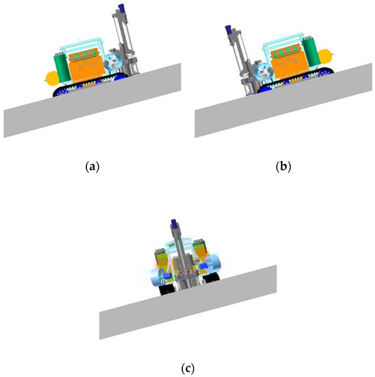
Figure 11.
Different orientations of the SMDV landing (a): forward, (b): backward, (c): lateral.
When the landing substrate is flat, the SMDV center of mass displacement, velocity, acceleration, and the angle between the SMDV and the substrate surface tend to be stable. When the substrate is inclined, the SMDV is unstable after landing due to the change in the spatial relationship of the center of mass concerning the inclined surface. During the simulation process, it was found that with the increase of the angle of the inclined plane, three states of stabilization, slippage, and overturning may occur after the SMDV lands on the substrate, as shown in Figure 12. When the slope angle is 35 degrees, the SMDV-to-slope angle after landing is not stable to 0 but exhibits periodic changes, and the corresponding SMDV speed component along the slope is not 0 but exhibits periodic changes over time; however, when the slope angle is 40 degrees, the SMDV-to-slope angle after landing is not stable to 0 but exhibits larger and more significant increases. The corresponding SMDV speed component is not 0 but increases to be larger and larger over time (Figure 13). When the slope lands on an angle of 35 degrees, the SMDV slides, and after landing at 40 degrees, the SMDV overturns. This paper defined the ultimate slipping angle as the maximum slope angle at which the SMDV becomes ensnared in sediment without slipping and the ultimate overturning angle as the maximum slope angle at which the SMDV is located on the slope without overturning.
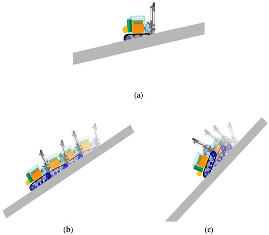
Figure 12.
State response of the SMDV after landing on different slopes (a): stable, (b): slipping, (c): overturning.
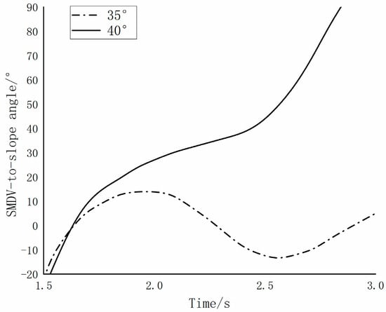
Figure 13.
The relationship between the variation of the SMDV-to-slope angle and the slope size (35° and 40°).
At first, the release height was established, the SMDV was divided into three different landing directions, and the slope was gradually increased. Ultimately, the SMDV’s attitude post-landing was observed in dynamic simulation. From this, it is possible to estimate the slope of the incline corresponding to the SMDV’s stable, slipping, and overturning state when it falls under a certain release height. This is the ultimate slipping angle and ultimate overturning angle of the SMDV. This means that the SMDV’s landing substrate is slipping when the slope is greater than the ultimate slipping angle but less than the ultimate overturning angle, stable when the slope is less than the ultimate slipping angle, overturning when the slope is greater than the ultimate overturning angle, and slipping when the slope is greater than the ultimate slipping angle but less than the ultimate overturning angle. As a result, for each release height, the ultimate slipping angle and the ultimate overturning angle corresponding to the three landing directions can be determined. The ultimate slipping and overturning angles under various release heights are connected into curves to obtain the relationship between the state of SMDV and the release height and slope under the three landing directions, as shown in Figure 14.
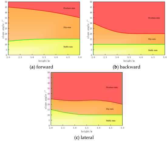
Figure 14.
Relationship between SMDV landing attitude and release height, slope angle (three landing directions).
The solid green line in the relationship graph between the SMDV landing attitude, release height, and slope angle separates the stable state from the slip state. The solid red line separates the slip state from the overturned state, with the overturned state located above the solid red line and the stable state below the solid green line. The slip state is represented by the region between the two solid lines, and it determines the landing attitude of the SMDV. Figure 13 illustrates how the risk of slip and overturning of the SMDV increases with slope inclination when it lands on the substrate. Under the same slope, the risk of slip and overturning of the vehicle is lowest in the forward direction of the substrate, and the risk of backward and lateral direction of the substrate is comparable. The effect of rig release height on the risk of slip and overturn is more complex. Relative to the three landing orientations, it either increases or decreases with changes in height, but the risk of slip and overturn tends to increase as the release height increases. Ensure that SMDV land safely. It is necessary to prevent them from slipping and overturning. When the currently developed SMDV is landing on the substrate in a certain sea area, under the condition that the release height is less than 5 m, the slope of the seabed substrate surface must be less than 10° in order to prevent slip. If it is permitted to allow a small amount of slip, the slope of the seabed substrate surface must be less than 15° in order to prevent overturning. This provides a theoretical foundation for securing SMDV and planning and formulating an acceptable landing program.
4. Conclusions
- (1)
- The mechanical parameters of deep-sea sediment substrate in a particular sea area are determined by pressure-sinkage and triaxial undrained and unconsolidated (UU) compression tests; the equivalent free-fall height is used instead of the release height because the SMDV is affected by water resistance and buoyancy when it is landing on the substrate; based on the specific structural design parameters of the SMDV, a multi-body dynamics model of the SMDV’s release fall trajectory is developed.
- (2)
- An experimental simulation of the SDMV at various release heights was conducted. Results showed that when the SMDV landed on a flat substrate, its subsidence increased gradually with the increasing release height, reaching a maximum of 347 mm at a release height of 5 m. At the same time, the center of gravity impact acceleration was less than seven gravity accelerations, ensuring the safety of electronic components on the body and normal operation of the SMDV after landing.
- (3)
- Experiments involving the simulation of the SMDV landing on slopes of different angles were conducted, and the results indicated that when the SMDV landed on the slope, it may take on three different states, namely stable, slip, and overturn. Among the three orientations in which the SMDV is placed—forward, backward, and lateral—the risk of slipping and flipping is the least when it is placed forward, and the risk is comparable when it is placed backward and lateral, with the increase of the release height of the SMDV. Its ultimate overturning angle decreases while the ultimate slipping angle remains nearly unchanged.
When deploying the SMDV in a certain target area, it is not easy to control the direction of the SMDV orientation to the slope of the seabed in practice. In order to avoid slipping the SMDV after release with a height less than 5 m, the slope of the seabed must be less than 10°. If a small amount of slipping is allowed, to prevent the SMDV from overturning after release, the slope of the seabed should not exceed 20°.
Author Contributions
Y.J. was in charge of the whole trial; R.H. wrote the manuscript; D.L. provided ideas on manuscript writing. All authors have read and agreed to the published version of the manuscript.
Funding
This work is supported by the National Key Research and Development Program of China (Grant No. 2022YFC2805904), the National Natural Science Foundation of China (Grant No. 52275106), and the special project for the construction of innovative provinces in Hunan (Grant No. 2020GK1021).
Institutional Review Board Statement
The study did not require ethical approval.
Informed Consent Statement
Not applicable.
Data Availability Statement
Data available on request from the authors. The data that support the findings of this study are available from the corresponding author, upon reasonable request.
Conflicts of Interest
The authors declare no conflict of interest.
References
- Liu, D.; Jin, Y.; Wan, B.; Peng, Y.; Huang, X. Review and development trends of deep-sea mineral resource core sampling technology and equipment. J. China Mech. Eng. 2014, 25, 3255. [Google Scholar]
- Liu, S.; Hu, J.; Zhang, R.; Dai, Y.; Yang, H. Development of mining technology and equipment for seafloor massive sulfide deposits. Chin. J. Mech. Eng. 2016, 29, 863–870. [Google Scholar] [CrossRef]
- Leng, D.; Shao, S.; Xie, Y.; Wang, H.; Liu, G. A brief review of recent progress on deep sea mining vehicle. Ocean Eng. 2021, 228, 108565. [Google Scholar] [CrossRef]
- Zhang, Q.; Zhang, Y.; Zhang, A. Research status of benthic small-scale crawling robots. Robot 2019, 41, 250–264. [Google Scholar]
- Brandt, A.; Gutt, J.; Hildebrandt, M.; Pawlowski, J.; Schwendner, J.; Soltwedel, T.; Thomsen, L. Cutting the umbilical: New technological perspectives in benthic deep-sea research. J. Mar. Sci. Eng. 2016, 4, 36. [Google Scholar] [CrossRef]
- Henthorn, R.G.; Hobson, B.W.; McGill, P.R.; Sherman, A.D.; Smith, K.L. MARS benthic rover: In-situ rapid proto-testing on the Monterey Accelerated Research System. In Proceedings of the OCEANS 2010 MTS/IEEE SEATTLE IEEE, Seattle, WA, USA, 20–23 September 2010; pp. 1–7. [Google Scholar]
- Watanabe, M.; Tashiro, S.; Momma, H. Loss of the full ocean depth ROV Kaiko–Part 3: The cause of secondary cable fracture. In Proceedings of the The Fourteenth International Offshore and Polar Engineering Conference, Toulon, France, 23–28 May 2004. [Google Scholar]
- Gao, Y.; Zhou, Y.; Guo, W.; Fu, Y.; Gao, S.; Wei, Z.; Sun, H.; Sun, Y. Design and Optimization of Multipoint Sampler for Seafloor Sediment Carried by a Deep-Sea Landing Vehicle. J. Mar. Sci. Eng. 2022, 10, 1937. [Google Scholar] [CrossRef]
- Hong, H.; Wang, H. Research on Assessment Method of Airbag Cushion System for Air dropping Equipment. J. Mech. Eng. 2015, 51, 148G54. [Google Scholar] [CrossRef]
- Li, H.; Cao, Y.; Sun, T.; Yang, S. Study on Suspension Breakdown of Tracked Vehicle when Running onto a Slope. Mech. Sci. Technol. Aerosp. Eng. 2017, 36, 621–625. [Google Scholar]
- Yang, Z.; Liu, C.; Li, J.; Guo, S.; Li, J. Dynamic Modeling and Simulation of Airborne Vehicle’s Landing Buffer Process. Acta Armamentarii 2022, 43, 26. [Google Scholar]
- Du, B.; Jiang, Y.; Zhang, H. Dynamic analysis of landing autonomous underwater vehicle. Trans. Tianjin Univ. 2012, 18, 298–304. [Google Scholar] [CrossRef]
- Yu, Z.; Zhang, C.; Chen, J.; Ren, Z. Dynamic analysis of substrate subsidence of benthic lander. J. Mar. Sci. Eng. 2022, 10, 824. [Google Scholar] [CrossRef]
- Wang, L.; Lu, Y.; Zhang, Y.; Chen, W.; Zhao, X.; Gao, F. Design and soft-landing control of underwater legged robot for active buffer landing on seabed. Ocean Eng. 2022, 266, 112764. [Google Scholar] [CrossRef]
- Hong, S.; Kim, H.-W.; Yeu, T.; Choi, J.-S.; Lee, T.H.; Lee, J.-K. Technologies for safe and sustainable mining of deep-seabed minerals. In Environmental Issues of Deep-Sea Mining; Springer: Berlin/Heidelberg, Germany, 2019; pp. 95–143. [Google Scholar]
- Zhang, T.; Dai, Y.; Liu, S.; Chen, J.; Huang, Z. Multi-body dynamic modeling and mobility simulation analysis of deep ocean tracked miner. J. Mech. Eng. 2015, 51, 173–180. [Google Scholar] [CrossRef]
- Dai, Y.; Su, Q.; Zhang, Y. A new dynamic model and trajectory tracking control strategy for deep ocean mining vehicle. Ocean Eng. 2020, 216, 108162. [Google Scholar] [CrossRef]
- Su, Q.; Lv, H.N.; Yang, J.M. Analysis of the walking performance of trackeddeep-sea mining vehicle on soft sediment. THE Ocean Eng. 2022, 40, 162–168. [Google Scholar]
- Long, Z.H.J.; Xu, Y. Virtual Simulation of ROV Mining VehicleLanding Process Based on ADAMS. Comput. Simul. 2004, 2004, 38–40. [Google Scholar]
- Shiosawa, T.; Takagi, K.; Inoue, T. Experimental and theoretical study on the motion of ROV with crawler system. In Proceedings of the OCEANS 2010 MTS/IEEE SEATTLE, Seattle, WA, USA, 20–23 September 2010. [Google Scholar]
- Guo, W.; Sun, H.; Xu, G.; Li, G.; Zhou, Y.; Wang, M. Improvements for Landing Impact Characteristics and Concentrated Stress Structures of Full Ocean Depth Landing Vehicles. China Mech. Eng. 2021, 32, 867. [Google Scholar]
- Bekker, M.G. Introduction to Terrain-Vehicle Systems; University of Michigan Press: Ann Arbor, MI, USA, 1969. [Google Scholar]
- Wong, J.Y.; Preston-Thomas, J. On the characterization of the shear stress-displacement relationship of terrain. J. Terramechanics 1983, 19, 225–234. [Google Scholar] [CrossRef]
- Wu, J.S.Y.; Yang, S.; Feng, Z. Simulation of Track-Soft Soil Interactions Using a Discrete Element Method. Appl. Sci. 2022, 12, 2524. [Google Scholar] [CrossRef]
- Dai, Y.; Xue, C.; Su, Q. An integrated dynamic model and optimized fuzzy controller for path tracking of deep-sea mining vehicle. J. Mar. Sci. Eng. 2021, 9, 249. [Google Scholar] [CrossRef]
- Yongli, H.U.; Hanjun, Y.I.N.; Shengwei, W.A.N.G.; Baoheng, Y.A.O.; Lian, L.I.A.N. Dynamic Response Analysis for Landing Collision of a New Underwater Lifting Device. J. Shanghai Jiaotong Univ. 2016, 50, 456. [Google Scholar]
- Dai, Y.; Xue, C.; Su, Q.; Huang, X. Numerical analysis on hydrodynamic characteristics of a deep-sea mining vehicle under three typical motions. Ocean Eng. 2021, 235, 109446. [Google Scholar] [CrossRef]


Disclaimer/Publisher’s Note: The statements, opinions and data contained in all publications are solely those of the individual author(s) and contributor(s) and not of MDPI and/or the editor(s). MDPI and/or the editor(s) disclaim responsibility for any injury to people or property resulting from any ideas, methods, instructions or products referred to in the content. |
© 2023 by the authors. Licensee MDPI, Basel, Switzerland. This article is an open access article distributed under the terms and conditions of the Creative Commons Attribution (CC BY) license (https://creativecommons.org/licenses/by/4.0/).