1. Introduction
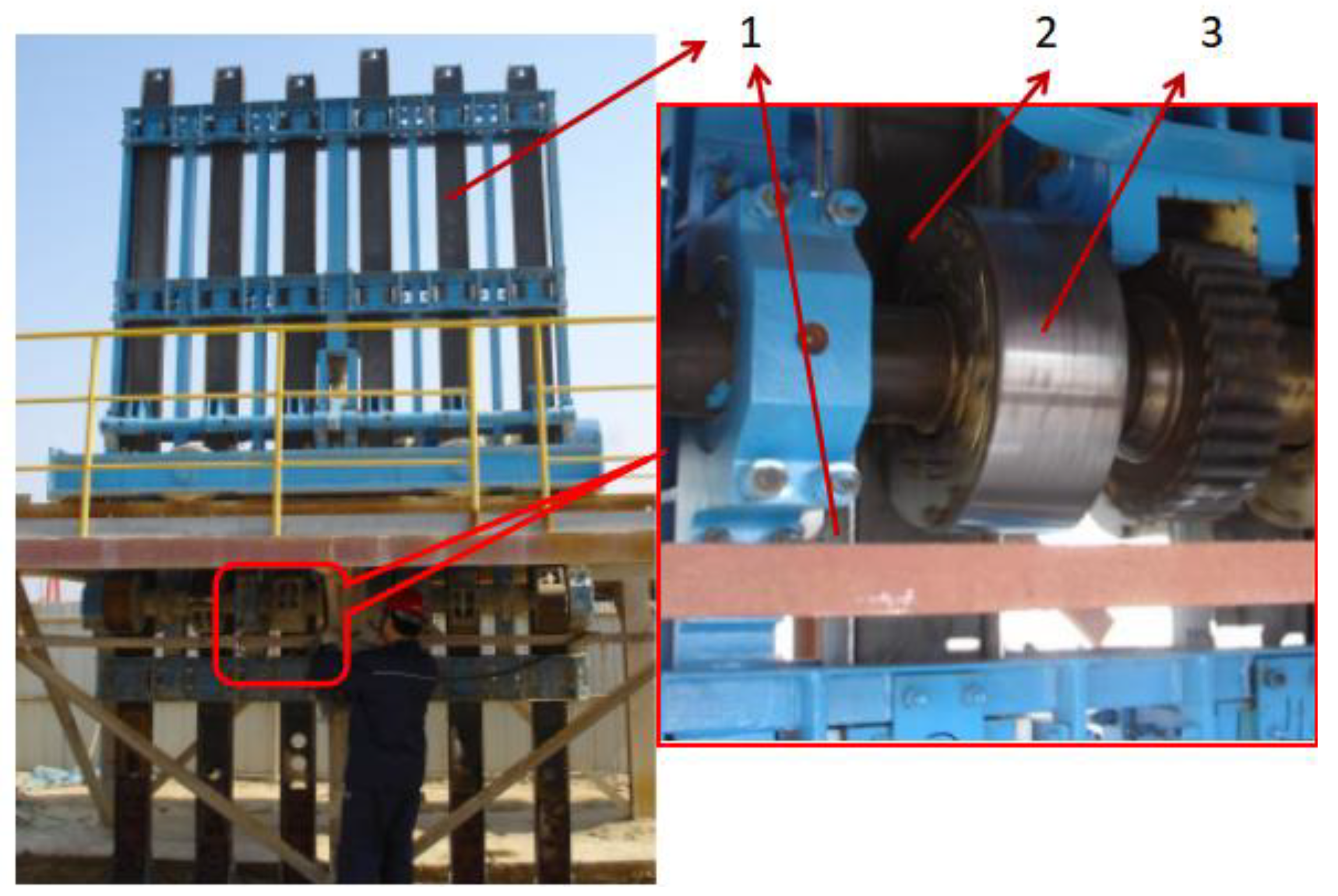
The coal cake tamper of the coke oven (as shown in
Figure 1) is a special type of equipment for tamping loose coal in the tamping box. By the continuous impact of the hammer, loose coal is compacted to form coal cakes with a specific pile density. The coal cake’s tamping quality directly affects coke production quality. The tamping hammer lifting device, which drives the tamping hammer, is a critical part of the coal cake tamping machine in the coke oven. Its principle is that a group of symmetrical rotating elastic cams intermittently clamp the tamping hammer to achieve the upward throwing and free falling of the hammer. The increasing demand for coal cake volume in large-scale coke ovens necessitates a higher quality and efficiency of coal cake tamping. This entails an increase in both the frequency and height of tamping, resulting in a more complex working load. After prolonged service, the cam elastic element often exhibits cracks and experiences elastic failure (as shown in
Figure 2a), resulting in inadequate lifting force and subsequent collapse of the coal cake (as shown in
Figure 2b).
The causes of these issues include unstable lifting force caused by constant variations in the contact point of the elastic cam, irregular changes in cam stiffness, as well as alterations in large deformation force during clamping. However, current research primarily focuses on the arrangements of tamping machine structures and mechanisms, while studies on the rubber elements mainly investigate how different fillers affect their constitutive behavior and predict mechanical properties related to their formation.
Regarding the tamping machine structure and pulverized coal tamping molding, scholars have carried out a considerable amount of research in recent years. Sun et al. [
1] established mathematical models of the maximum positive pressure and maximum drag moment of the cam mechanism, carried out a dynamic analysis on the cam mechanism of the tamping hammer, and obtained the dynamic regulation of the tamping hammer lifting device. Peng [
2] analyzed the problem from the perspective of SCP machine control and proposed corresponding optimization measures. Fan [
3] optimized the frame structure of the tamping machine. Gabriel et al. [
4,
5] summarized the elastic–plastic regulation of pulverized coal under a certain blending ratio during the tamping process through a scale model experiment. It was concluded that the density and strength of briquettes after tamping molding were related to the tamping work. Dash et al. [
6] studied the effect of ash content on the density and strength of coal briquettes after tamping to improve the yield of coal briquettes after tamping, and finally obtained the optimal coal mix ratio. Kim et al. [
7] established a three-dimensional model of pulverized coal based on the discrete element method, studied the influence of pulverized coal pores on coke strength, and provided a reference for improving the stacking performance of pulverized coal. These studies are mainly focused on the structure of the tamping machine, the lower frame and the layout of the camshaft phase difference, and the ratio of coal powder and the strength of the coal cake itself. However, the influence of the mechanical properties of the elastic cam itself on the extrusion force between the cam and the tamping hammer is seldom studied.
In terms of the finite element simulation method of rubber and cam, Perez et al. [
8] used finite element modelling simulations to predict wear in the cams processed. Guo et al. [
9] proposed an adaptive p-version finite element method in their paper for the solution of 3D cam problems, and they solved the concrete-like particle-reinforced composite problems with that method. Maitland et al. [
10] used finite element simulation to improve forward motion on cross-slopes compared with single- or double-cantilever spring designs. Louay et al. [
11] calculated the bending deflection of the cam profile numerically and verified it for bending deflection at the point of contact by the finite element analysis method. Wang et al. [
12] obtained the deformation and stress of the rubber components and the cord reinforcements by FE simulation to judge the rationality of tire construction design. Limrungruengrat et al. [
13] obtained predictions of the temperature, cure level distribution in the rubber part, and press force during a curing process from a developed finite element analysis. These studies have mainly used the finite element method to analyze structural wear, strength, and stiffness, and few have applied it to constitutive coefficient simulation and automatic search of the material properties of rubber materials.
In studies of rubber elements constitutive models, most scholars have focused on rubber’s molecular mechanical properties and composite materials’ properties. Besdo et al. [
14] presented a new phenomenological inelastic constitutive model for rubberlike materials and demonstrated its good correspondence to cyclic measurements for both uniaxial tension and simple shear tests up to large deformations. Kumar et al. [
15] researched a phenomenological model for the viscoelastic behavior of natural rubber and its mechanical behavior. He et al. [
16] developed a fitting algorithm that can realize the automatic fitting optimization and determination of the parameters of all SEFs reviewed. This algorithm could quantitatively assess the ability of each SEF to reproduce the experimental data of both unfilled and highly filled rubber nanocomposites. Annarasa et al. [
17] proposed a one-dimensional constitutive model for elastomeric materials and captured the changes in constitutive behavior and energy dissipation associated with the Mullins effect. Jha et al. [
18] proposed a novel phenomenological constitutive modeling framework that incorporates damage and residual stress capabilities for solids. Yuan et al. [
19] first attempted the analysis of the constitutive relations of filled rubber by calculating amplification factors related to stress and strain distributions. Liu et al. [
20] established a constitutive model of rubber compound material with the shear strain energy of cord/rubber and compiled the subprograms involved in a constitutive model of anisotropic hyper-elastic materials. The subprograms were used to form an effective prediction method for the deformation behavior of cord/rubber composites. Zhao et al. [
21] proposed an optimization algorithm for model parameters fitting and predicted the mechanical behaviors of rubber–cord composites using the developed model. Kurzina et al. [
22] studied the elastic hysteretic properties of various polymer-damping composite materials. Dong et al. [
23] studied the mechanical properties of complex fabric–rubber composite under different temperatures based on macroscopic and meso-structural characterization. Khodadadi et al. [
24] investigated the impact performance of composite panels consisting of plain-woven Kevlar fabric and rubber matrix. And they investigated the deformation and damage mechanism of fabric and composite under impact loading. All in all, most scholars have studied the influence of different rubber fillers on the rubber constitutive structure and the prediction of rubber-forming mechanical properties. However, few scholars have studied a large deformation constitutive model of rubber under different theories and the mechanical properties of composite rubber structures.
Given the aforementioned issues, in conjunction with the operational characteristics of the hammer-lifting device and the rubber test data, this paper establishes a large deformation constitutive model of rubber based on phenomenological theory and derives distinct coefficients for the rubber constitutive model. Additionally, a simulation model is presented to investigate the mechanical characteristics of composite rubber elements during cam rotation. The resulting variations in elastic cam pressure and compression displacement are determined, while also designing an elastic cam stiffness test and discussing discrepancies between experimental and simulated results. The innovations of this paper are as follows:
(1) A constitutive model of the large deformation of rubber based on phenomenological theory is proposed to obtain the relationship between stress and strain under large deformation of rubber. The comparison error between rubber stress based on this method and test data is less than 2%.
(2) A mathematical model of the change of cam compression displacements in lifting the tamping hammer is presented by analyzing the motion characteristics of the elastic cam and the tamping hammer. By establishing a finite element model of the elastic cam and simulating the loading under the contact condition, the variation regulation of the cam pressure with different compression displacements is obtained. And the distribution regulation of the stress and displacement of the composite rubber elements inside the cam is obtained.
(3) A method for measuring the stiffness of the elastic cam is presented, and the test platform is designed and built. Finally, the stiffness curve of the elastic cam is obtained. Experiments verify the correctness and rationality of the simulation results of the elastic cam. The error between cam simulation stiffness and test stiffness is less than 6.18%.
The rest of this paper is organized as follows.
Section 2 introduces the calculation method for compression displacement of composite rubber elements in cam rotation. The establishment of the nominal stress and elongation function based on the large deformation of rubber and the determination of different rubber constitutive model coefficients based on test data are introduced in
Section 3. The simulation analysis of the mechanical properties of composite rubber elements is presented in
Section 4. The stiffness test for elastic cams is introduced in
Section 5. Finally,
Section 6 summarizes the conclusions of this paper and
Section 7 presents the prospect of this research work.
2. Change Analysis of Compression Displacement of Composite Rubber Elements in Cam Rotation
The tamping hammer lifting device is mainly composed of cams, composite rubber elements, friction plates, and tamping hammer rods. Since the tamping hammer lifting device has a symmetrical structure, to simplify the model and shorten the analysis time, a unilateral cam was selected for force analysis, as shown in
Figure 3. Each cam is mainly composed of a cam plate, rubber elements, fixed circular plate, intermediate rib plate, double-headed stud, and circular skeleton. When the cam plate is subjected to the load, the force is directly transmitted to the fixed circular plate on both sides. Then, the force is transmitted to one end of composite rubber elements by the fixed circular plate. Finally, the force is transmitted to the internal rib plate through the composite rubber elements. The composite rubber elements refer to the 20 rubber elements that an elastic cam contains. The tamping action is produced by the cam pair rotating relatively opposite on both sides of the tamping hammer to generate extrusion friction to lift the tamping hammer. In the process of cam rotation, the displacement and radial force of the composite rubber elements are continuously changing, which is related to the contact state between the cam profile and the friction plate of the hammer rod.
In
Figure 3, when the cam rotates to the arc DA, the cam does not squeeze the hammer and the composite rubber elements do not deform. Meanwhile, the composite rubber elements will not provide pressure to the cam. As the cam continues to rotate and the contact point of the cam profile and the friction plate is on arc AB, the cam begins to squeeze the tamping hammer, and the composite rubber elements begin to deform, providing pressure to the cam. However, the pressure provided at this time does not reach the maximum. When the contact point between the cam profile and the friction plate is on arc BC, the displacement of composite rubber elements reaches the maximum and provides the maximum pressure to the cam. As the cam continues to rotate, when the contact point between the cam profile and the friction plate is on arc CD, the displacement of the composite rubber elements gradually decreases, and its pressure also gradually decreases. Finally, when the cam rotates to the arc DA section, the displacement of composite rubber elements is zero again, and the pressure provided is also zero. Therefore, the motion process of the tamping lift hammer is divided into four stages: initial contact—stable extrusion—imminent separation—complete separation, as shown in
Figure 4. Studying the stress state of the cam and its internal rubber elements in a circle is to study the change of compression displacement
Xi at each moment when the cam arc ABCD and friction plate contact; the force changes of the composite rubber elements are caused by the
Xi change, as shown in
Figure 5.
As shown in
Figure 3, in section AB, the compression displacement of
Xi during cam movement is:
where
X0 is the distance between the center of the intermediate rib of the cam and the edge of the friction plate of the tamping hammer.
As shown in
Figure 5, according to the sine theorem in △
O1O2Ai, it can be seen that:
Similarly, it can be obtained, in section BC:
in section CD:
By substituting Equations (3)–(5) into Equation (1), the cam compression
Xi of different arc sections of the cam plate is:
Positive cam pressure
FN is:
where
kj is the stiffness of the rubber element, N/mm.
The unilateral friction force
Ff of the tamping hammer is:
where
µ is the coefficient of friction.
According to Newton’s second theorem:
where
mc is the tamping hammer quality, kg;
ac is the acceleration of tamping hammer motion, m/s
2.
4. Simulation Analysis of Mechanical Properties of Composite Rubber Elements
4.1. Establishment and Simplification of Simulation Model of Composite Rubber Elements
As the whole structure of the elastic cam extruding and lifting the tamping hammer was geometrically symmetrical, a unilateral cam was selected for simulation analysis to improve the computation rate. The simplified finite element model is shown in
Figure 11. The cam plate, fixed circular plate, intermediate rib plate, and press plate were discretized using a C3D8R hexahedral element, and the total number of grids was 65,000. The rubber elements were discretized using a C3D8RH hexahedral hybrid element, and the total number of grids for the 20 rubber elements was 246,160. The cam inner and outer plate element type was C3D8R, and the total number of grids was 64,500. In addition to the rubber material, the piecewise-function rubber constitutive data were brought into the finite element model, and the material properties of other parts are shown in
Table 3.
As shown by the rubber element on the right in
Figure 11, the cylindrical hole of the rubber element on the middle rib plate side and the stud of the middle rib plate were set to bind contact constraints. The lower circular plane of the rubber element and the intermediate rib plate were provided with binding contact constraints. The cylindrical hole of the rubber element on the fixed circular plate side and the stud of the bolt on the fixed circular plate were set to bind contact constraints. The upper circular plane of the rubber element and the fixed circular plate were provided with binding contact constraints.
In the finite element loading model of the elastic cam, the usual hard contact was set between the cam plate and the press plate, and the tangential contact was set with no friction property. The inner surface of the intermediate rib plate was coupled with the cam center, and all degrees of freedom at the coupling point were restricted.
In the load setting, all degrees of freedom except U1 were restricted on the shaft hole surface of the outer fixed circular plate of the cam, and the position of the shaft hole of the intermediate rib plate of the cam was fully constrained. At the coupling point RP1, different displacements in the direction of U1 were set, and degrees of freedom in other directions were restricted. The analysis step type was static general, and the analysis step duration was set to 1s. The deformation process of the cam extrusion of the friction plate of the tamping hammer was simulated, and the changing characteristics of the cam pressure on the composite rubber elements under different cam compression displacements were obtained.
4.2. Stress and Displacement Analysis of the Rubber Element
Firstly, the stress and strain analysis of the single rubber element was performed, and the single rubber element was divided into the same element type and number of grids as in the figure on the right in
Figure 11. All degrees of freedom were restricted for the cylindrical hole of the rubber element connected to the middle rib plate. Two planes of the rubber element were constrained by displacement in U3 direction only. The degrees of freedom except in U1 direction were restricted at the cylindrical hole of the rubber element connected to the fixed circular plate. The compression displacement in the direction of U1 of the cylindrical hole of the rubber element connected to the fixed round plate was 3 mm. The analysis step type was static general, and the analysis step duration was set to 1 s. The stress and the displacement distribution of a single rubber element at 3 mm were obtained.
Figure 12a shows the stress nephogram of the rubber element at a compression displacement of 3 mm. It can be seen from
Figure 12a that the stress of the rubber element was mainly distributed around the cylindrical hole connected with the fixed circular plate, and the stress gradually decreased from the right half of the inner part of the cylindrical hole to the right end.
The reason for this result is that the stiffness of the bolt is greater than the stiffness of the rubber element, and when the bolt squeezes the rubber element, the top of the bolt compresses the cylindrical hole surface at the bottom of the rubber element as the bolt moves. With the increase in bolt pressure, the relative dislocation of the cylindrical holes at both ends of the rubber element becomes more significant, and the support reaction also increases.
Figure 12b shows the stress nephogram of the rubber element in section view when the compression displacement of the rubber element was 3 mm. According to
Figure 12b, the maximum stress of the rubber element was 1.717 MPa, the maximum stress position was on the dividing line of the upper and lower semicircle of the cylindrical hole of the bolt, and the main bearing area was within about 160° of the radiation area of the lower half surface of the cylindrical hole. The reason is that when the elastic cam is rotating the extrusion tamping hammer, with the change in the actual contact radius, the bolt on the cam fixed round plate will transfer the force to the elastic element inner hole, and in the extrusion transition area of the rubber element cylindrical hole there will appear stress concentration.
In actual working conditions, each time the cam rotates, its rubber elements will undergo a process of extrusion and deformation recovery; therefore, the rubber elements are subjected to alternating stress in duty-cycle operation, and these rubber elements are prone to fatigue failure. The location of fatigue failure in the rubber element is mainly in the contact range of 160° between the cylindrical hole of the rubber element and the bolt of the fixed circular plate, and at the two stress concentration positions of the bolt hole it is the most significant.
Figure 13 shows the stress nephograms of the rubber elements at different times. With the increase in time, the stress also increased continuously. The maximum stress was mainly concentrated on both sides of the cylindrical hole circumference, and the main load-bearing area was below the cylindrical hole circumference. At 0.25 s, 0.5 s, 0.75 s, and 1 s, the corresponding maximum stress was 0.355 MPa, 0.761 MPa, 1.216 MPa, and 1.717 MPa, respectively.
As can be seen from the displacement nephogram of the rubber element under a downward compression displacement of 3 mm in
Figure 14, the rubber deformation was mainly concentrated in the lower half of the cylindrical hole of the rubber element, and gradually expanded downward. The rubber element was tilted to the lower right, and the two cylindrical holes inside were relatively misaligned. The rubber deformation caused by the dislocation provided a reliable lifting force for the tamping device, thus ensuring the lifting of the tamping hammer. The downward dislocation of the rubber element is caused by the contact between the cylindrical hole surface on the left side of the rubber element and the bolt on the intermediate rib plate of the cam, and the right bolt hole surface is connected with the bolt on the fixed circular plate on the outside of the cam.
This is because, in the actual rotation process of the cam, with the contact between the cam and the friction plate on both sides of the hammer rod, the fixed circular plate of the cam will move in the same direction with the bolt. The bolt on the fixed circular plate provides pressure to the hole surface of the rubber element, and the other end of the rubber element is fixed on the intermediate rib plate of the cam. The joint action of the cam’s inner and outer plate bolts causes the dislocation of the rubber element.
4.3. Influence of Displacement of Composite Rubber Elements on Cam Pressure
Figure 15 shows the stress nephograms of composite rubber elements under different compression displacements. It can be seen from the figure that the maximum stress of the composite rubber elements under 3 mm, 5 mm, 7 mm, and 9 mm displacements were 0.725 MPa, 1.114 MPa, 1.528 MPa, and 1.979 MPa, respectively. With the increase in the compression displacement of the cam, the overall stress on the rubber element gradually increased. The trend and values of the stress distribution for each of the 20 rubber elements inside the cam were the same, indicating that the stress distribution for all the rubber elements was relatively even.
This is because the outside cylindrical holes of the 20 rubber elements are all fixed with the bolts of the fixed circular plate on the outside of the cam. The material stiffness of the fixed circular plate and the bolt stiffness are much higher than that of the rubber element. When the cam plate is under pressure, because the relative deformation of the fixed circular plate and the bolt is very small, it can be regarded as a rigid body, so they move in the direction of the cam plate pressure as a whole. This results in the force direction of the outer cylindrical hole of the rubber element in contact with the bolt, and the size is basically the same.
As can be seen from the displacement nephograms of the composite rubber elements under different compression displacements in
Figure 16, the maximum displacement of the composite rubber elements under the pressures of 3 mm, 5 mm, 7 mm, and 9 mm were 4.082 mm, 6.127 mm, 8.175 mm, and 10.23 mm, respectively. With the increase in the compression displacement of the cam, the displacement of the rubber element also increased gradually, and the maximum displacement was concentrated on the connection surface between the rubber element and the outer fixed circular plate of the cam. The deformation distribution trend and values for each of the 20 rubber elements inside the cam were the same, indicating that the deformation for all the rubber elements was relatively even during the deformation process of the composite rubber elements, which could provide stable positive pressure for the elastic cam.
This is because the diameter of the middle hole of the fixed circular plate on the outside of the cam is larger than that of the cam intermediate rib plate fixed shaft, as shown in
Figure 3a. Therefore, when the fixed circular plate on the outside of the cam is under pressure, the fixed circular plate drives the outside cylindrical holes of the 20 rubber elements to shift in the pressure direction as a whole. And because the material stiffness and bolt stiffness of the fixed circular plate are much greater than the stiffness of the rubber element, the relative deformation of the fixed circular plate and bolt is small, so the lateral deformation of the rubber element is basically the same, and the value is basically the same.
Figure 17 shows the stress nephograms of a cam under different compression displacements. As can be seen from
Figure 17, the maximum stress was mainly distributed in the local position of the contact between the press plate and the cam, and the stress was much lower than the allowable stress of the cam material. The maximum contact stress between the cam and the press plate increased from 33.75 MPa to 113.5 MPa with compression increasing from 3 mm to 9 mm.
This is because, with the cam under increasing compression displacements, the displacement of the rubber elements inside the cam is also increasing, and the elastic force provided by the elastic elements is also greater, making the contact pressure between the cam and the press plate increase.
Figure 18 shows the pressure change of the elastic cam under different compression displacements. With the increase in the displacement of the composite rubber elements, the pressure it provided to the cam also gradually increased, and the relationship between the displacement and the pressure of the cam was approximately linear. When the displacement is 1 mm, the cam pressure is about 7715 N; when the displacement is 5 mm, the cam pressure is 22,909 N; when the displacement is 10 mm, the cam pressure is 40,000 N. It can provide sufficient lifting force when the displacement is in the range of 3~5 mm and the cam pressure is in the range of 15,300 N~23,000 N.


