Experimental Study and Bearing Capacity Analysis of Retrofitted Built-Up Steel Angle Members under Axial Compression
Abstract
:1. Introduction
2. Retrofitting Test on Steel Angles
2.1. Specimen Design
2.2. Material Property
2.3. Test Program
2.4. Failure Mode
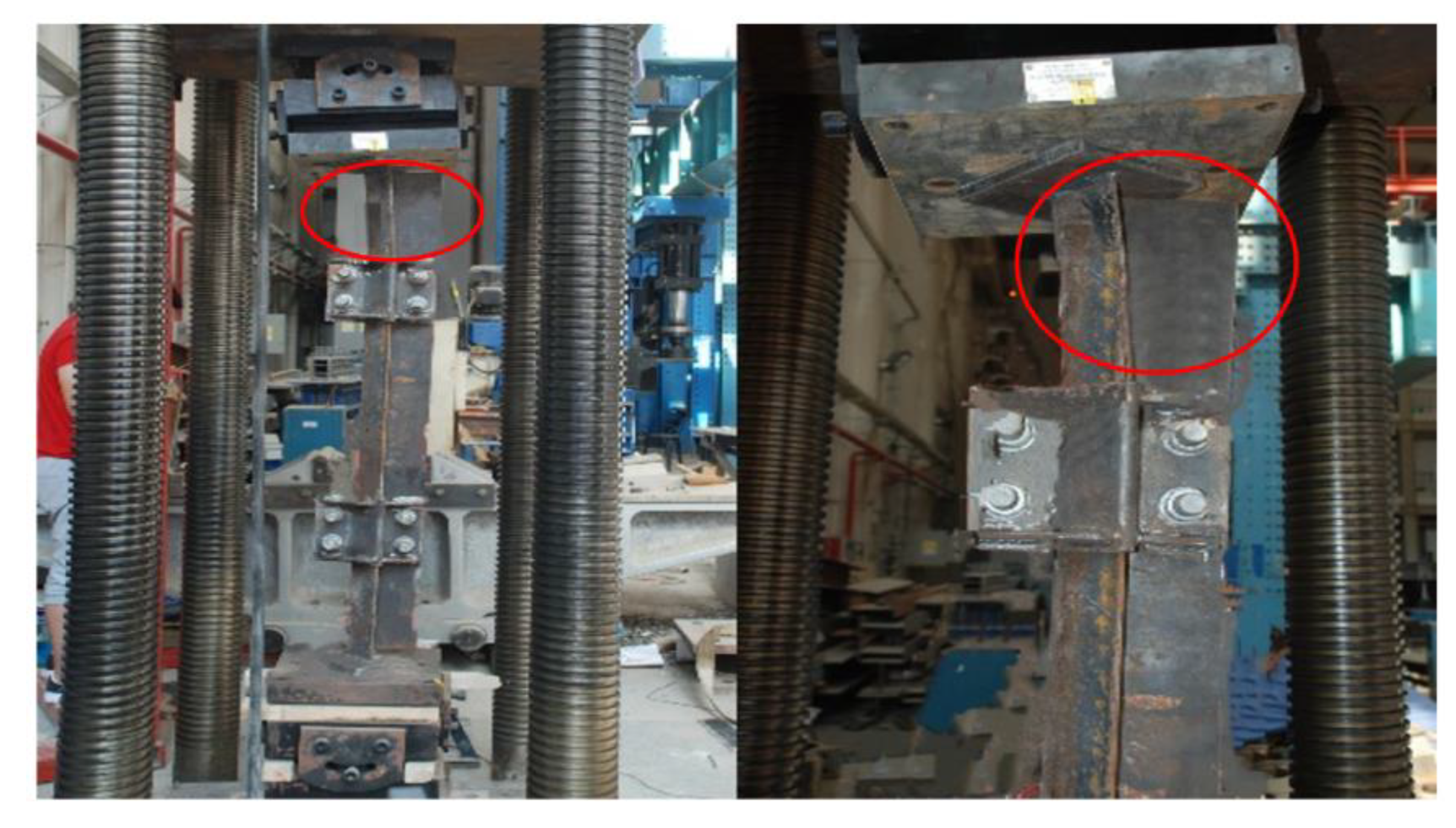
2.4.1. Flexural–Buckling Mode
2.4.2. Flexural–Torsional Buckling Mode
2.4.3. Local Buckling Mode
3. Analysis of Test Results
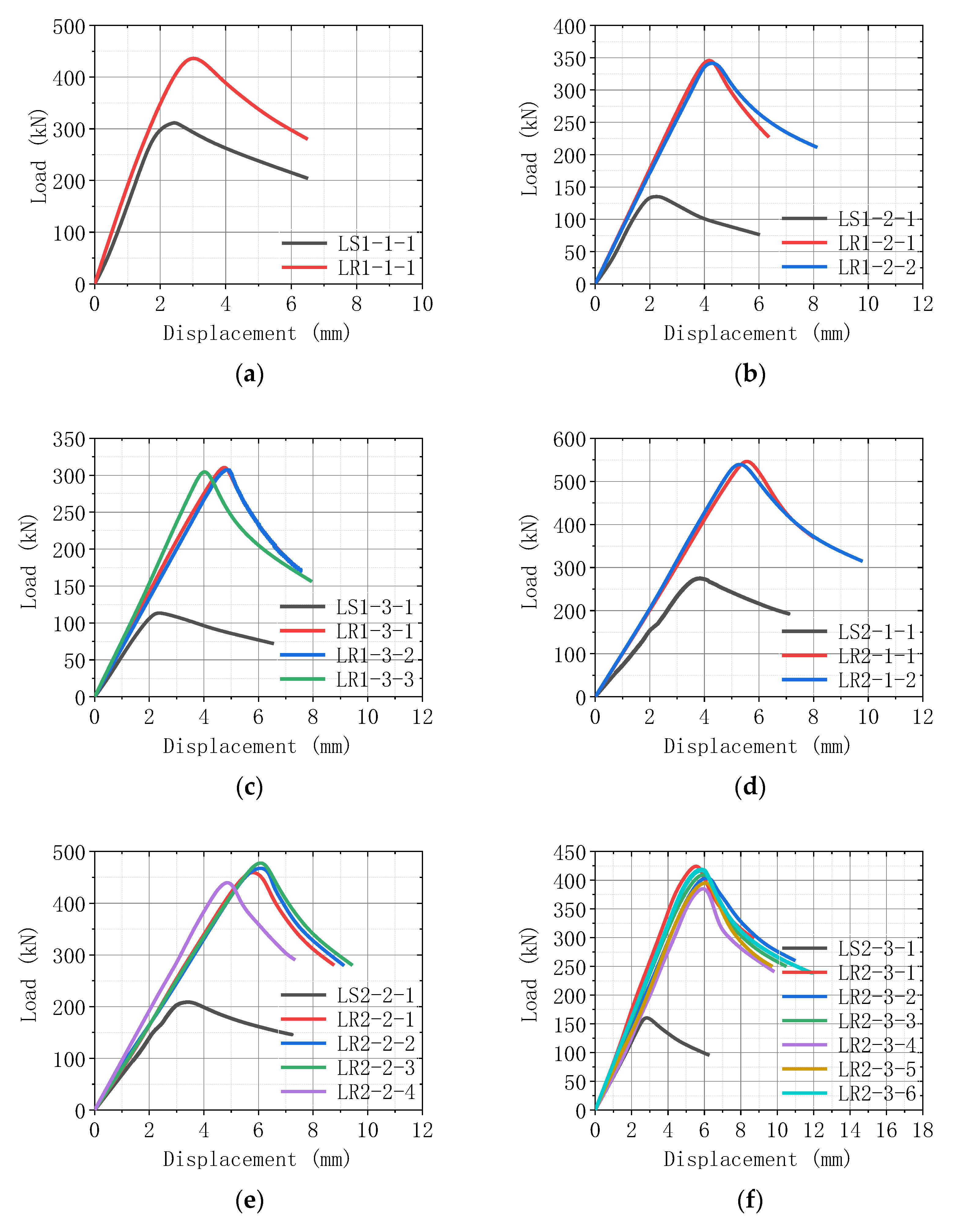
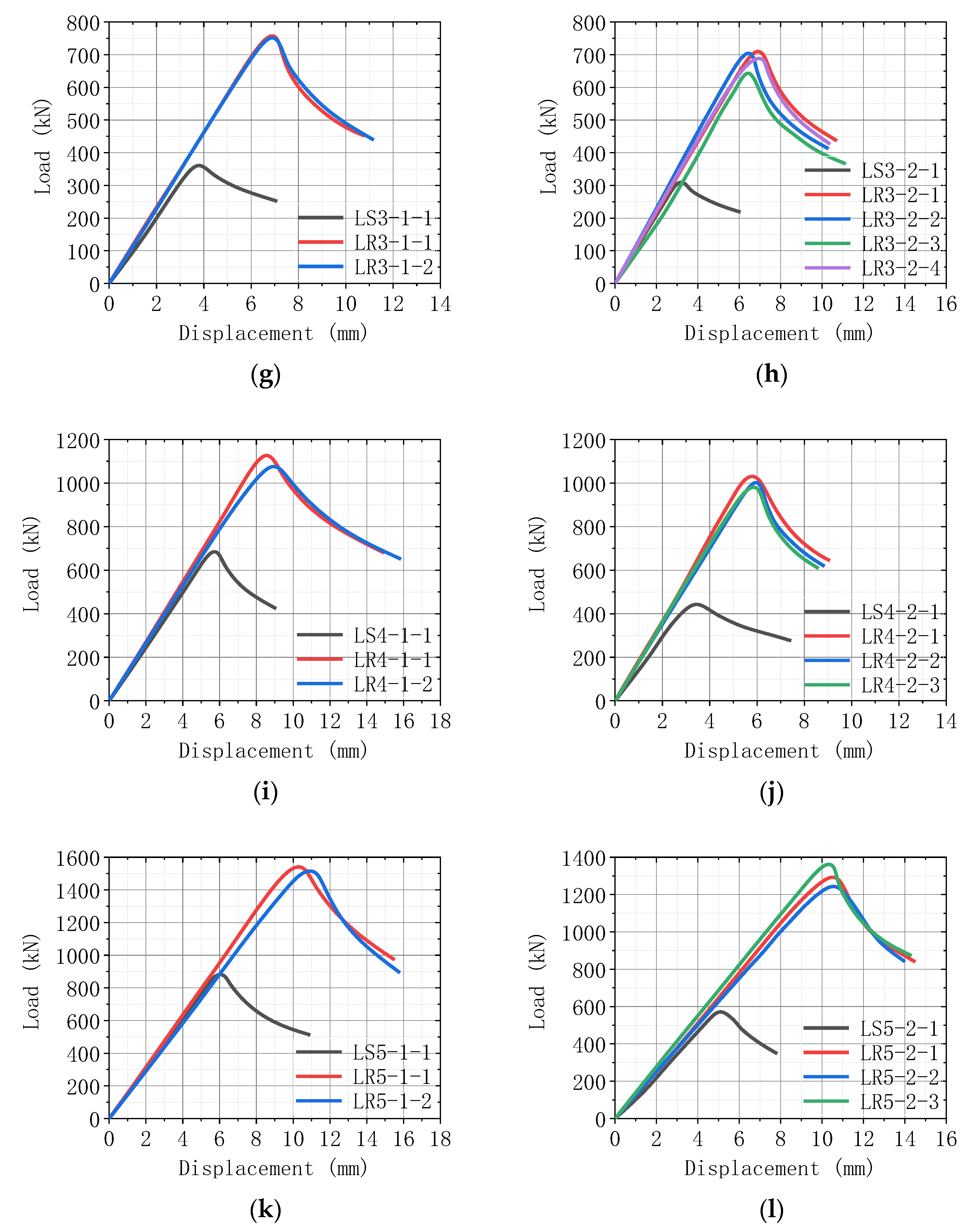
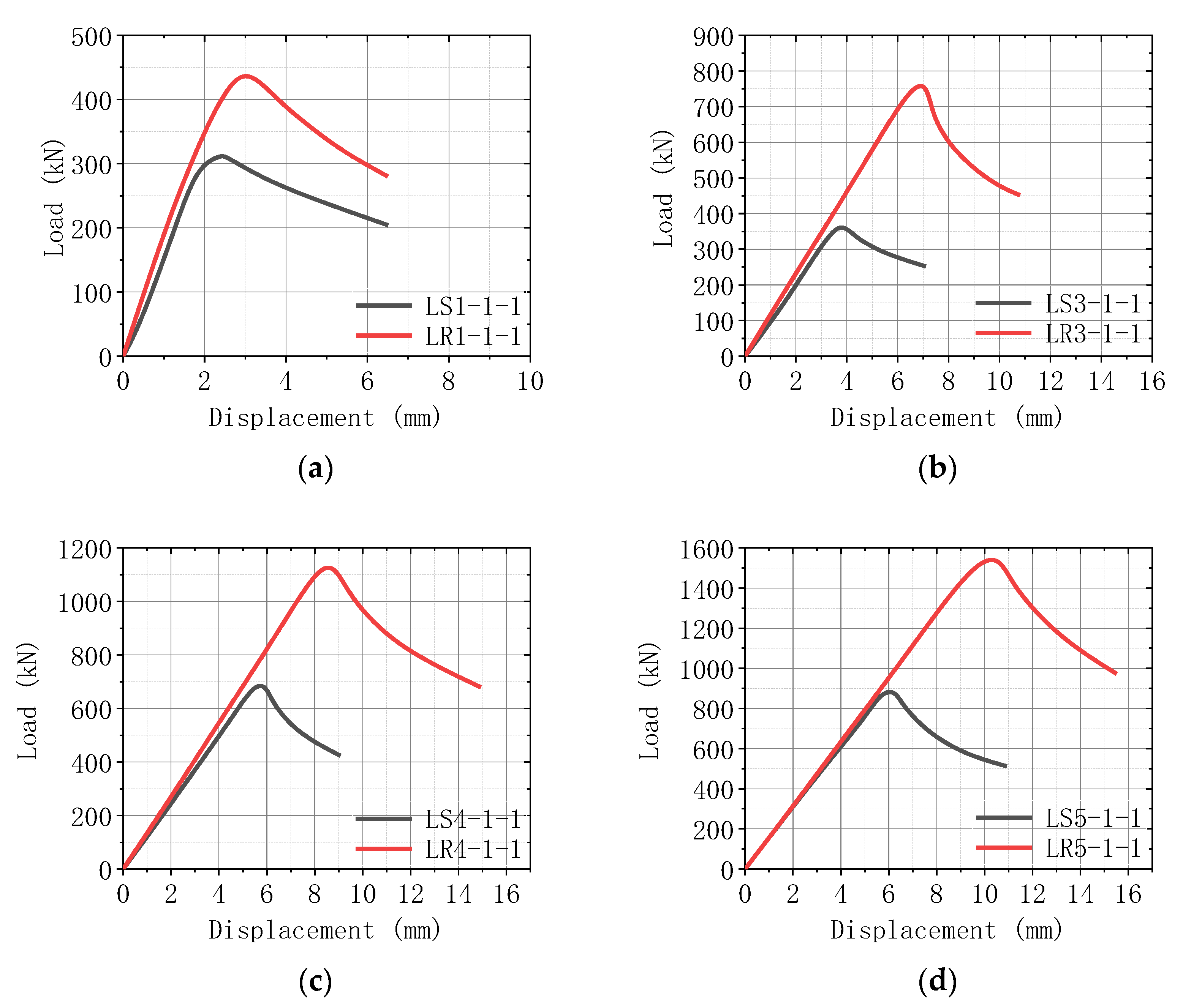
3.1. Load–Displacement Curves
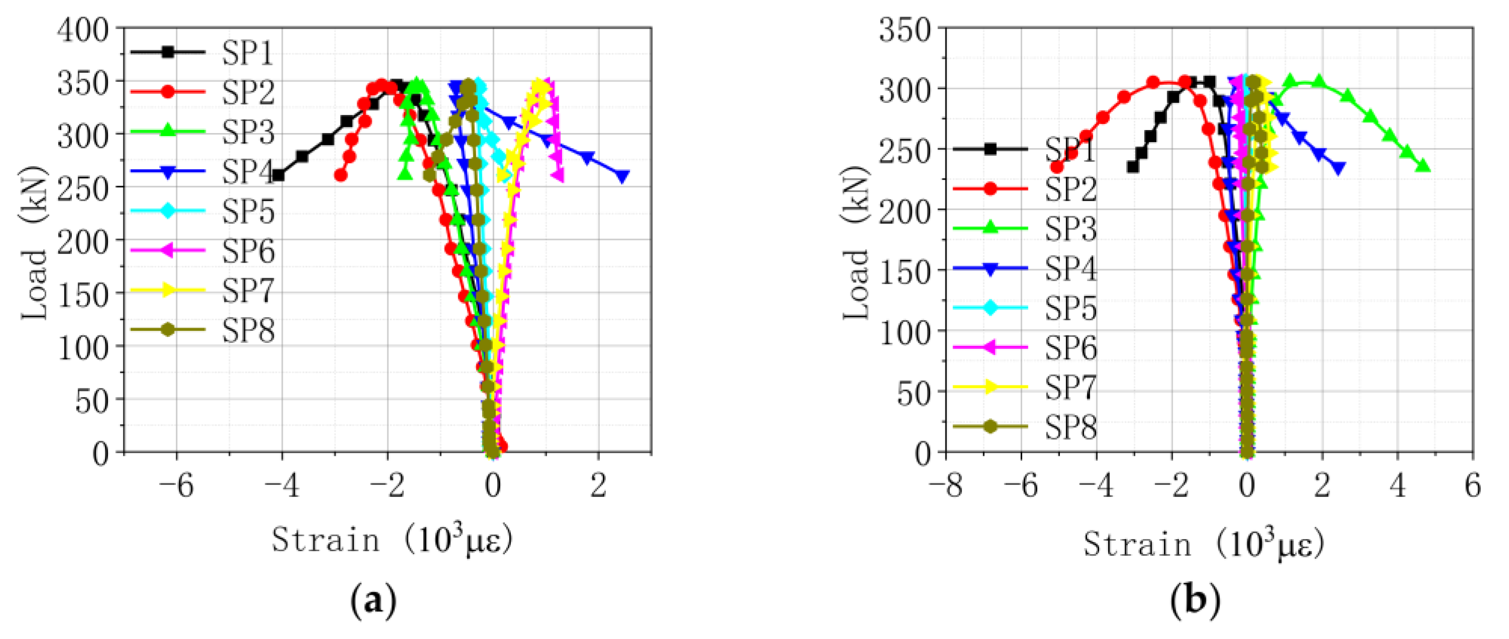
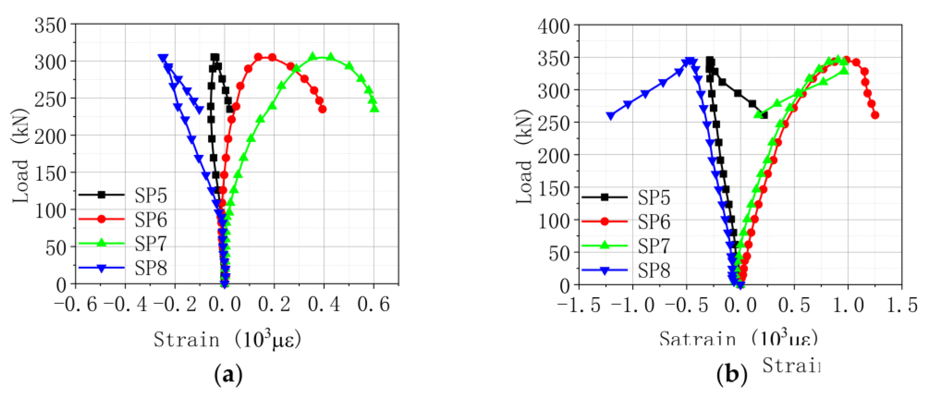
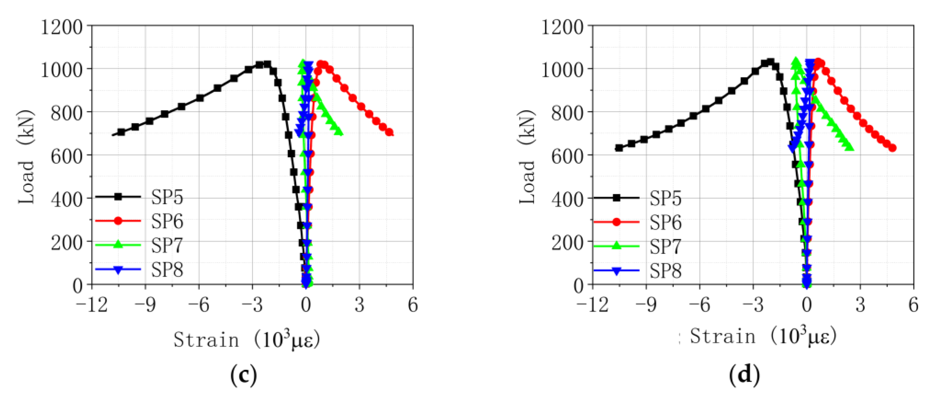
3.2. Strain Analysis
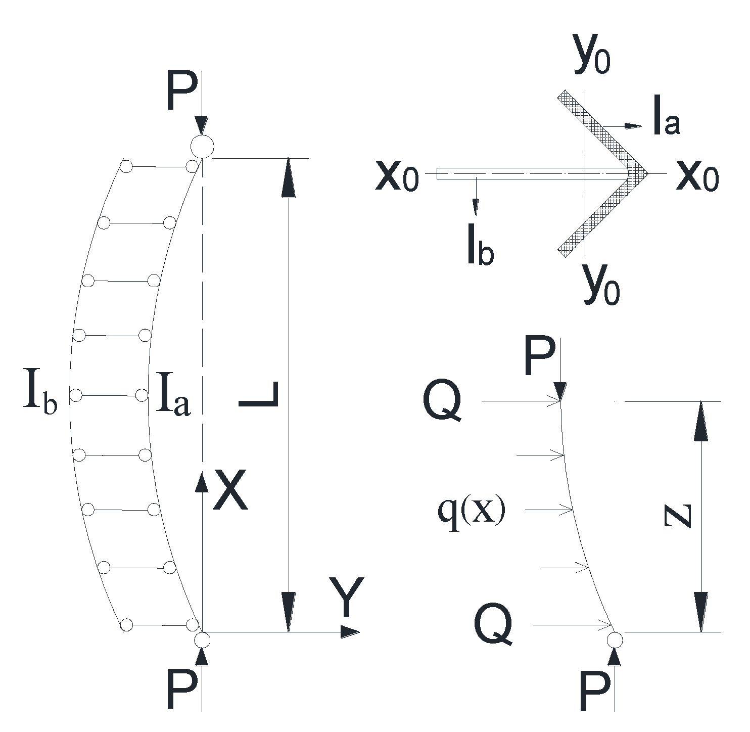
3.3. Mechanism of Reinforcement Plate
4. Prediction on Ultimate Bearing Capacity
4.1. Bearing Capacity of Flexural–Buckling Mode
4.2. Bearing Capacity of Flexural–Torsional Buckling Mode
5. Conclusions
- (1)
- Three failure modes of flexural-buckling mode, flexural–torsional buckling mode, and local buckling mode may occur for built-up steel angle members under axial compression. The width of the reinforcement plate has a significant impact on the failure mode. Failure of the local buckling mode can be avoided by reducing the clamp distance to the member end.
- (2)
- The bearing capacity of the reinforced steel angles is increased by 39~174%, indicating that the reinforcement effect of the proposed non-destructive method is significant. The increment ratio of bearing capacity is positively correlated with the slenderness ratio, reflecting that the reinforcement method is more effective for slender members. The clamp types and clamp distance behave a slight effect on bearing capacity.
- (3)
- By analyzing the reinforcement mechanism of reinforced angle steel, it indicates that the reinforcement plate is not subjected to axial compression; namely, it does not participate in the distribution of vertical load and only balances the secondary bending moment through the squeezing force with the steel angle.
- (4)
- A simplified mechanical model of reinforced steel angle members (built-up steel angles) is established under bending instability. Moreover, a design method based on existing codes is proposed to predict the flexural–torsional capacity by considering the effect of the reinforcement plate. The verification result indicates that the design method based on AISC 360-16 has better agreement with the experimental results and could be used as a basis for calculating the flexural–torsional bearing capacity of reinforced steel angles.
Author Contributions
Funding
Institutional Review Board Statement
Informed Consent Statement
Data Availability Statement
Acknowledgments
Conflicts of Interest
References
- Baran, E.; Akis, T.; Sen, G.; Draisawi, A. Experimental and numerical analysis of a bolted connection in steel transmission towers. J. Constr. Steel Res. 2016, 121, 253–260. [Google Scholar] [CrossRef]
- Kang, X.; Zhang, Y. Dynamic analysis of communication transmission tower based on finite element method. In Proceedings of the International Conference on Artificial Intelligence and Engineering Applications, Hong Kong, China, 12–13 November 2016. [Google Scholar]
- Szafran, J.; Rykaluk, K. A full-scale experiment of a lattice telecommunication tower under breaking load. J. Constr. Steel Res. 2016, 120, 160–175. [Google Scholar] [CrossRef]
- Fu, X.; Li, H.N.; Li, G. Fragility analysis and estimation of collapse status for transmission tower subjected to wind and rain loads. Struct. Saf. 2016, 58, 1–10. [Google Scholar] [CrossRef]
- Han, J.; Zhao, X.; Tang, Z.; Ma, H.; Li, Z. Study on the bearing capacity of cold-formed steel under different boundary conditions in transmission towers. Earthq. Struct. 2017, 12, 665–672. [Google Scholar]
- Xie, Q.; Sun, L. Experimental study on the mechanical behavior and failure mechanism of a latticed steel transmission tower. J. Struct. Eng. 2013, 139, 1009–1018. [Google Scholar] [CrossRef]
- Gayathri, B.; Ramalingam, R. Joint stress based deflection limits for transmission line towers. Steel Compos. Struct. 2018, 26, 45–53. [Google Scholar]
- Egidi, C.A.; Saravia, M.D.R.; Ballaben, J.S.; Rosales, M.B. Reinforcement of Lattice Structures with Applications to Communication Towers Retrofiting. Mec. Comput. 2011, 30, 1133–1142. [Google Scholar]
- Tapia-Hernández, E.; Cervantes-Castillo, J.A. Influence of the drag coefficient on communication towers. Int. J. Civ. Eng. 2018, 16, 499–511. [Google Scholar] [CrossRef]
- An, L.; Wu, J.; Zhang, Z.; Zhang, R. Failure analysis of a lattice transmission tower collapse due to the super typhoon Rammasun in July 2014 in Hainan Province, China. J. Wind Eng. Ind. Aerod. 2018, 182, 295–307. [Google Scholar] [CrossRef]
- Gao, S.; Zeng, C.; Zhou, L.; Liu, X.; Gao, B. Numerical analysis of the dynamic effects of wine-cup shape power transmission tower-line system under ice-shedding. Structures 2020, 24, 1–12. [Google Scholar] [CrossRef]
- Zheng, H.D.; Fan, J.; Long, X.H. Analysis of the seismic collapse of a high-rise power transmission tower structure. J. Constr. Steel Res. 2017, 134, 180–193. [Google Scholar] [CrossRef]
- Alam, M.J.; Santhakumar, A.R. Reliability analysis and full-scale testing of transmission tower. J. Struct. Eng. 1996, 122, 338–344. [Google Scholar] [CrossRef]
- Kitipornchai, S.; Albermani, F. Upgrading of transmission towers using tension bracing diaphragm. In Progress in Mechanics of Structures and Materials, 1st ed.; CRC Press: Christchurch, New Zealand, 2020; pp. 13–16. [Google Scholar]
- Dostatni, C. Analysis, Design, and Strengthening of Communication Towers. Ph.D. Thesis, University of Windsor, Windsor, ON, Canada, 2011. [Google Scholar]
- Meshmesha1a, H.M.; Kennedy2b, J.B.; Sennah3c, K.; Moradi, S. Static and dynamic analysis of guyed steel lattice towers. Struct. Eng. Mech. 2019, 69, 567–577. [Google Scholar]
- Albermani, F.; Mahendran, M.; Kitipornchai, S. Upgrading of transmission towers using a diaphragm bracing system. Eng. Struct. 2004, 26, 735–744. [Google Scholar] [CrossRef] [Green Version]
- Xie, Q.; Sun, L. Failure mechanism and retrofitting strategy of transmission tower structures under ice load. J. Constr. Steel Res. 2012, 74, 26–36. [Google Scholar] [CrossRef]
- Lanier, B.K. Study in the Improvement in Strength and Stiffness Capacity of Steel Multi-Sided Monopole Towers Utilizing Carbon Fiber Reinforced Polymers as a Retrofitting Mechanism. Ph.D. Thesis, North Carolina State University, Raleigh, NC, USA, 2005. [Google Scholar]
- Balagopal, R.; Prasad Rao, N.; Rokade, R.P.; Umesha, P.K. Experimental Investigation on Strengthening of Bolted Connections in Transmission/Communication Towers. J. Inst. Eng. Ser. A 2018, 99, 269–277. [Google Scholar] [CrossRef]
- Yoresta, F.S.; Maruta, R.; Mieda, G.; Matsumoto, Y. Unbonded CFRP strengthening method for buckling control of steel members. Constr. Build. Mater. 2020, 241, 118050. [Google Scholar] [CrossRef]
- Mills, J.E.; Ma, X.; Zhuge, Y. Experimental study on multi-panel retrofitted steel transmission towers. J. Constr. Steel Res. 2012, 78, 58–67. [Google Scholar] [CrossRef]
- Yan, Z.; Mills, J.E.; Ma, X. Modelling of steel lattice tower angle legs reinforced for increased load capacity. Steel Constr. 2012, 43, 160–168. [Google Scholar]
- Mills, J.E. Modelling and parametric analysis of bolted connections on retrofitted transmission tower leg members. In Proceedings of the 23rd Australasian Conference on the Mechanics of Structures and Materials, Byron Bay, Australia, 9–12 December 2014. [Google Scholar]
- Trovato, M.; Sun, L.; Stojadinovic, B. Buckling restrained brace retrofit technique for existing electric power transmission towers. In Proceedings of the 8th International Conference on Behavior of Steel Structures in Seismic Areas, Shanghai, China, 1–3 July 2015. [Google Scholar]
- Lu, C.; Ma, X.; Mills, J.E. Modeling of retrofitted steel transmission towers. J. Constr. Steel Res. 2015, 112, 138–154. [Google Scholar] [CrossRef]
- Lu, C.; Ma, X.; Mills, J.E. Cyclic performance of reinforced legs in retrofitted transmission towers. Arch. Civ. Mech. Eng. 2018, 18, 1608–1625. [Google Scholar] [CrossRef]
- Ananthi, G.B.G.; Roy, K.; Chen, B.; Lim, J.B. Testing, simulation and design of back-to-back built-up cold-formed steel unequal angle sections under axial compression. Steel Compos. Struct. 2019, 33, 595–614. [Google Scholar]
- Dar, M.A.; Sahoo, D.R.; Jain, A.K. Axial compression behavior of laced cold-formed steel built-up columns with unstiffened angle sections. J. Constr. Steel Res. 2019, 162, 105727. [Google Scholar] [CrossRef]

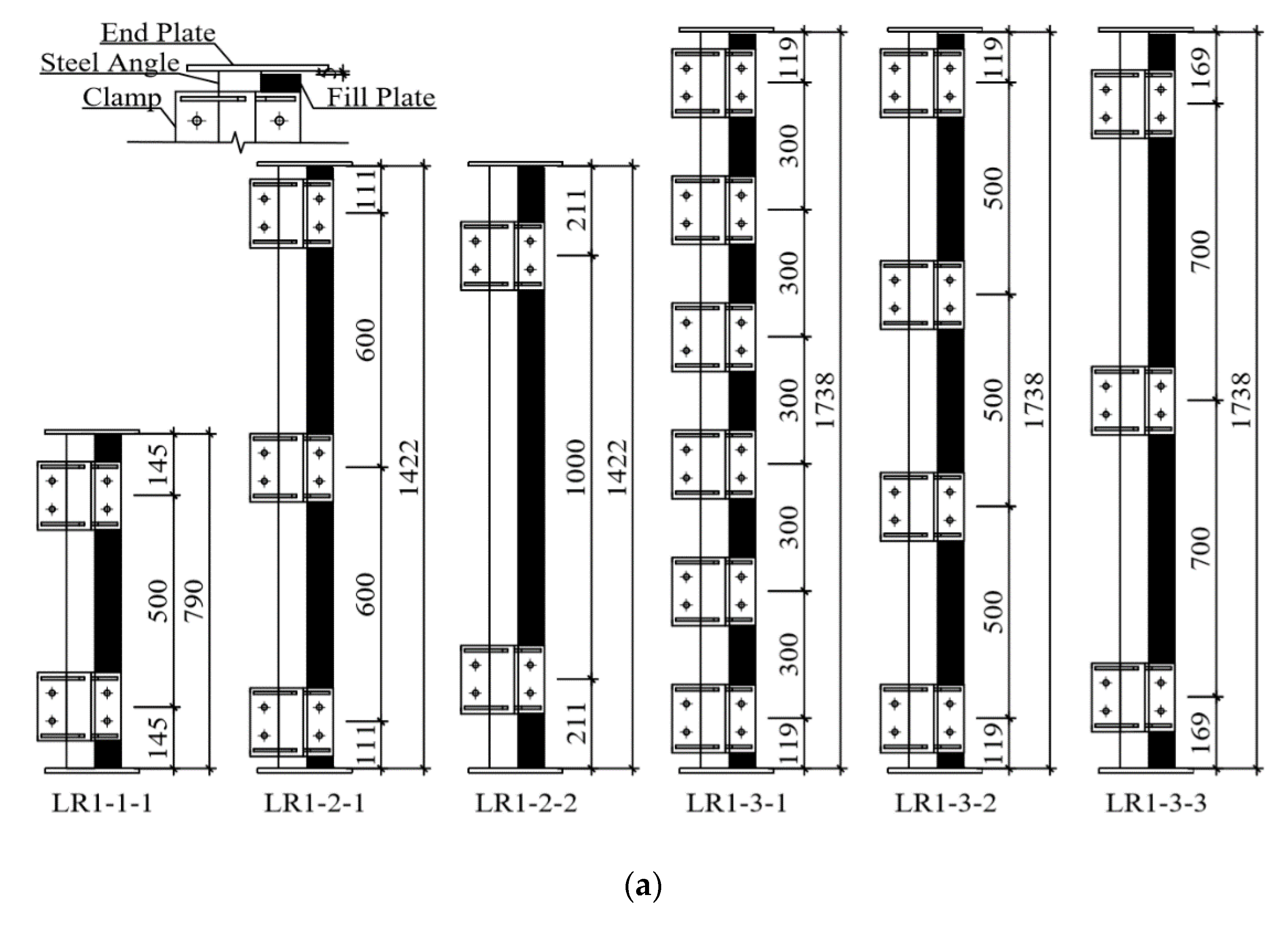

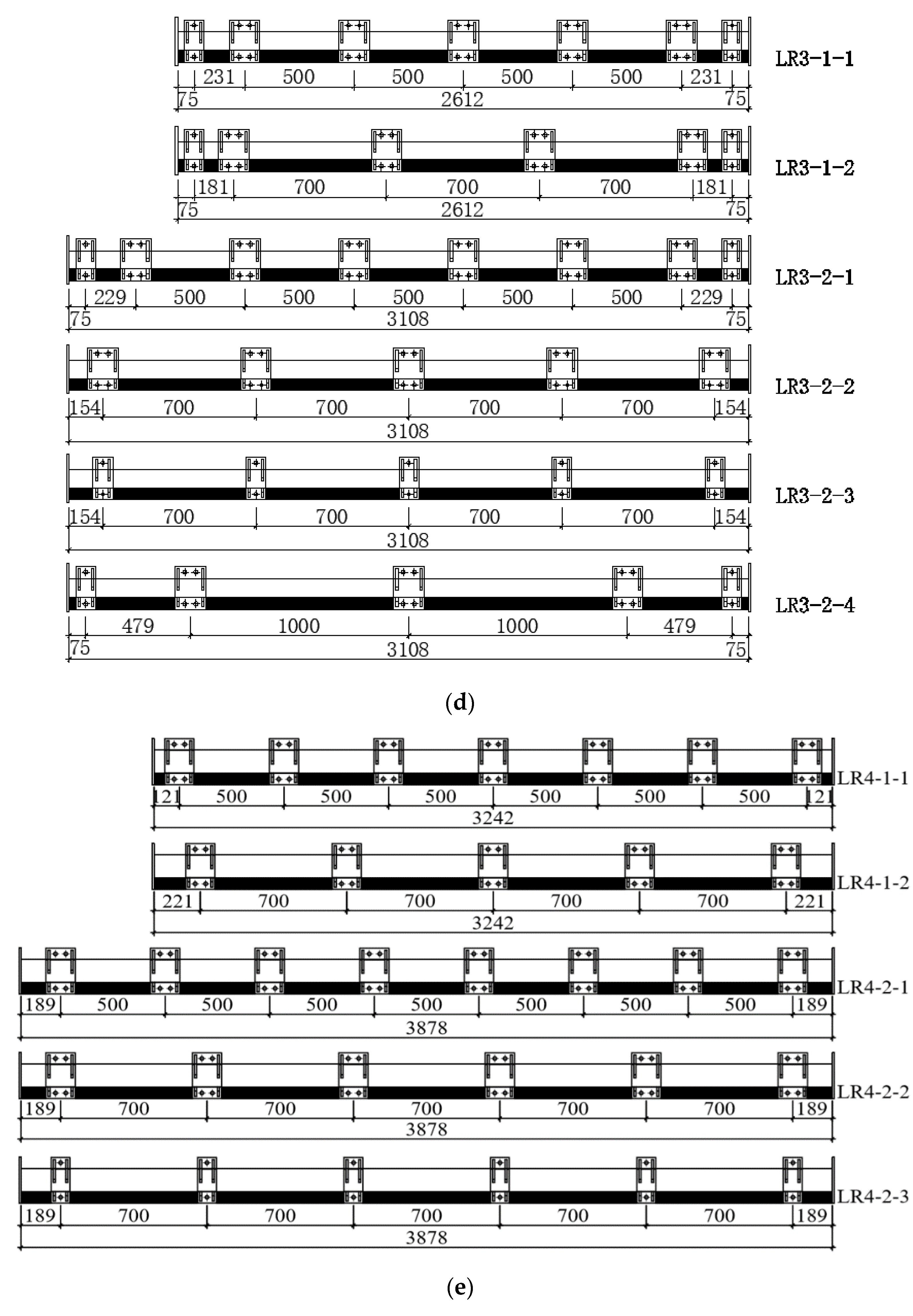


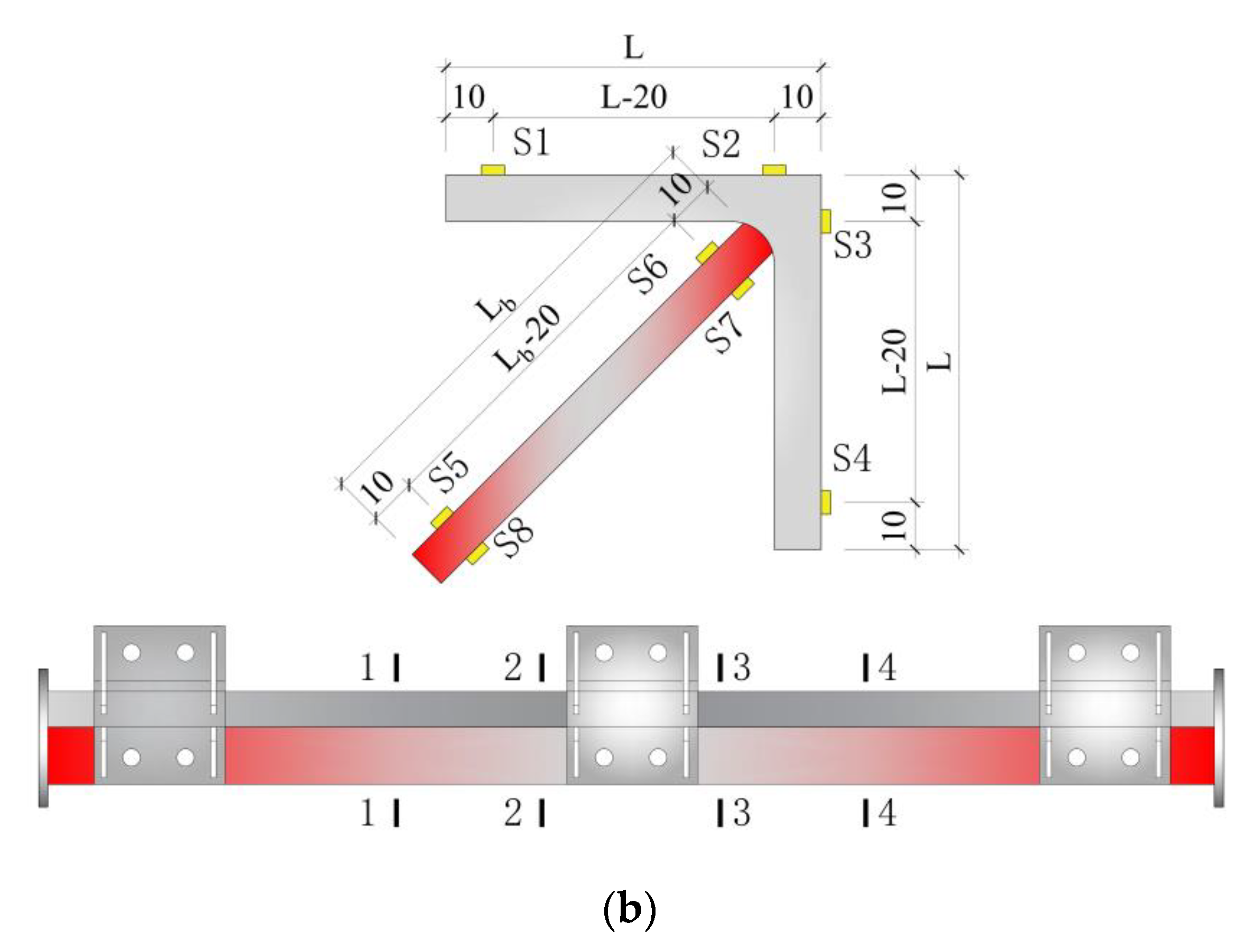

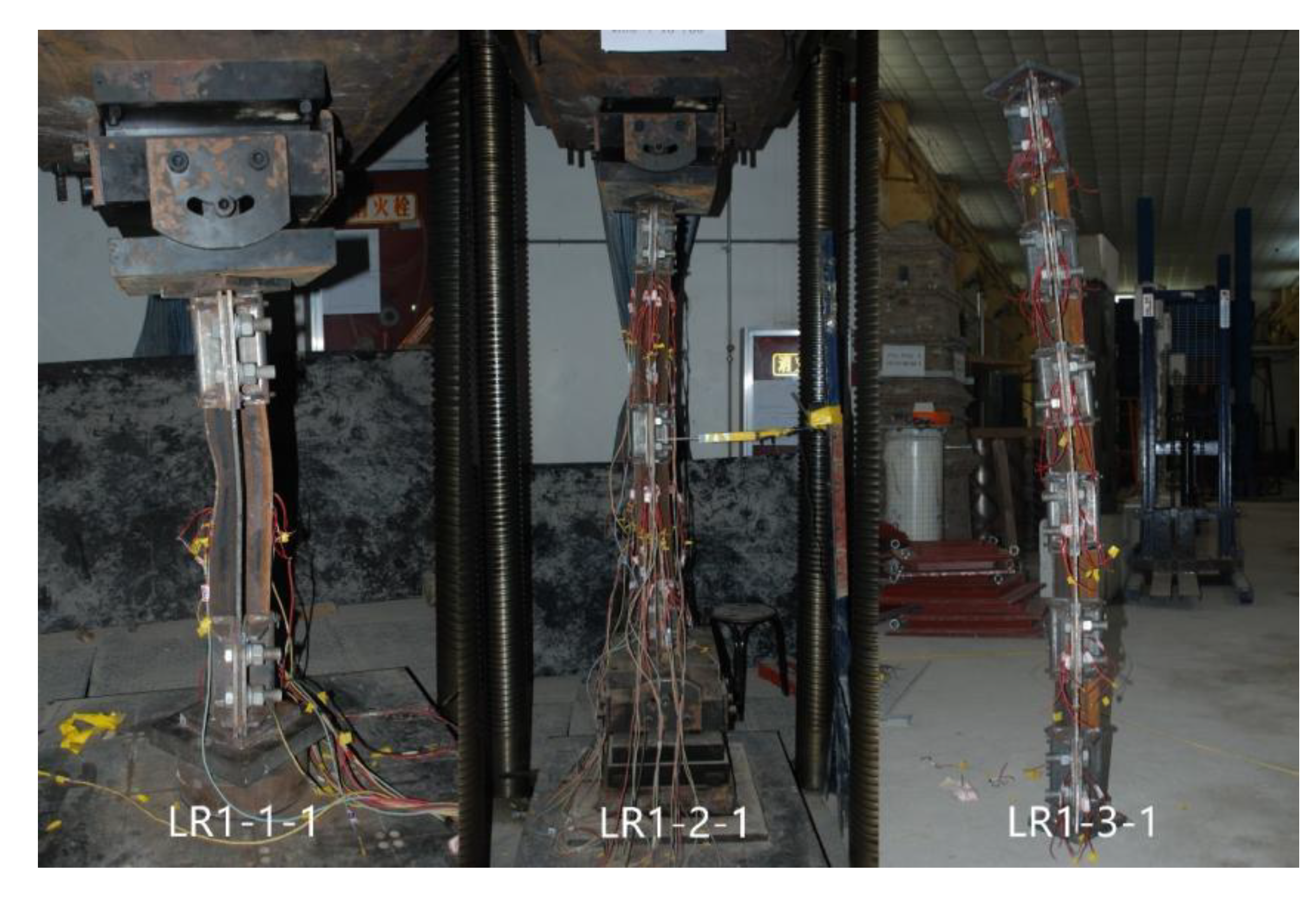


| Type | No. | Slenderness Ratio | Width of Reinforcement Plate/mm | Length of Reinforcement Plate/mm | Retrofitting Distance/mm | Clamp Type |
|---|---|---|---|---|---|---|
| L80 × 7 | LS1-1-1 | 50 | \ | \ | \ | \ |
| LR1-1-1 | 50 | 137 | 780 | 500 | Double-bolt | |
| LS1-2-1 | 90 | \ | \ | \ | \ | |
| LR1-2-1 | 90 | 137 | 1412 | 600 | Double-bolt | |
| LR1-2-2 | 90 | 137 | 1412 | 1000 | Double-bolt | |
| LS1-3-1 | 110 | \ | \ | \ | \ | |
| LR1-3-1 | 110 | 137 | 1728 | 300 | Double-bolt | |
| LR1-3-2 | 110 | 137 | 1728 | 500 | Double-bolt | |
| LR1-3-3 | 110 | 137 | 1728 | 700 | Double-bolt | |
| L100 × 8 | LS2-1-1 | 90 | \ | \ | \ | \ |
| LR2-1-1 | 90 | 151 | 1772 | 500 | Double-bolt | |
| LR2-1-2 | 90 | 151 | 1772 | 700 | Double-bolt | |
| LS2-2-1 | 110 | \ | \ | \ | \ | |
| LR2-2-1 | 110 | 151 | 2168 | 500 | Double-bolt | |
| LR2-2-2 | 110 | 151 | 2168 | 700 | Double-bolt | |
| LR2-2-3 | 110 | 151 | 2168 | 700 | Single-bolt | |
| LR2-2-4 | 110 | 151 | 2168 | 1000 | Double-bolt | |
| LS2-3-1 | 130 | \ | \ | \ | \ | |
| LR2-3-1 | 130 | 151 | 2564 | 500 | Double-bolt | |
| LR2-3-2 | 130 | 151 | 2564 | 500 | Single-bolt | |
| LR2-3-3 | 130 | 151 | 2564 | 700 | Double-bolt | |
| LR2-3-4 | 130 | 151 | 2564 | 700 | Single-bolt | |
| LR2-3-5 | 130 | 151 | 2564 | 1000 | Double-bolt | |
| LR2-3-6 | 130 | 151 | 2564 | 1000 | Single-bolt | |
| L125 × 10 | LS3-1-1 | 90 | \ | \ | \ | \ |
| LR3-1-1 | 90 | 168 | 2212 | 500 | Double-bolt | |
| LR3-1-2 | 90 | 168 | 2212 | 700 | Double-bolt | |
| LS3-2-1 | 110 | \ | \ | \ | \ | |
| LR3-2-1 | 110 | 168 | 2718 | 500 | Double-bolt | |
| LR3-2-2 | 110 | 168 | 2718 | 700 | Double-bolt | |
| LR3-2-3 | 110 | 168 | 2718 | 700 | Single-bolt | |
| LR3-2-4 | 110 | 168 | 2718 | 1000 | Double-bolt | |
| L160 × 12 | LS4-1-1 | 90 | \ | \ | \ | \ |
| LR4-1-1 | 90 | 193 | 2852 | 500 | Double-bolt | |
| LR4-1-2 | 90 | 193 | 2852 | 700 | Double-bolt | |
| LS4-2-1 | 110 | \ | \ | \ | \ | |
| LR4-2-1 | 110 | 193 | 3488 | 500 | Double-bolt | |
| LR4-2-2 | 110 | 193 | 3488 | 700 | Double-bolt | |
| LR4-2-3 | 110 | 193 | 3488 | 700 | Single-bolt | |
| L180 × 14 | LS5-1-1 | 90 | \ | \ | \ | \ |
| LR5-1-1 | 90 | 207 | 3203 | 700 | Double-bolt | |
| LR5-1-2 | 90 | 207 | 3203 | 1500 | Double-bolt | |
| LS5-2-1 | 110 | \ | \ | \ | \ | |
| LR5-2-1 | 110 | 207 | 3917 | 700 | Double-bolt | |
| LR5-2-2 | 110 | 207 | 3917 | 700 | Single-bolt | |
| LR5-2-3 | 110 | 207 | 3917 | 1000 | Double-bolt |
| Type | Yield Strength (fy)/MPa | Ultimate Strength (fu)/MPa | Elastic Modulus (Es)/GPa | Poisson’s Ratio | Elongation/% |
|---|---|---|---|---|---|
| L80 × 7 | 396 | 535 | 199.6 | 0.282 | 27.4 |
| L100 × 8 | 378 | 527 | 205.1 | 0.289 | 27.3 |
| L125 × 10 | 384 | 531 | 205.3 | 0.287 | 26.6 |
| L160 × 12 | 383 | 539 | 201.3 | 0.296 | 27.2 |
| L180 × 14 | 394 | 540 | 207.5 | 0.298 | 28.9 |
| Retrofitted Specimens | Bearing Capacity of Retrofitted Specimens/kN | Steel Angles | Bearing Capacity of Steel Angles/kN | Capacity Enhancement | Calculation of Bearing Capacity for Weak Axis of Steel Angles/kN | Calculation of Bearing Capacity for Strong Axis of Steel Angles/kN |
|---|---|---|---|---|---|---|
| LR1-1-1 | 437.18 | LS1-1-1 | 314.09 | 39.19% | 270.87 | 378.35 |
| LR1-2-1 | 345.33 | LS1-2-1 | 136.39 | 153.19% | 146.42 | 323.49 |
| LR1-2-2 | 339.45 | 148.88% | ||||
| LR1-3-1 | 312.26 | LS1-3-1 | 113.69 | 174.66% | 97.59 | 291.74 |
| LR1-3-2 | 306.12 | 169.26% | ||||
| LR1-3-3 | 303.45 | 166.91% | ||||
| LR2-1-1 | 547.03 | LS2-1-1 | 275.38 | 98.65% | 228.68 | 458.37 |
| LR2-1-2 | 539.22 | 95.81% | ||||
| LR2-2-1 | 459.59 | LS2-2-1 | 210.36 | 118.48% | 157.55 | 417.03 |
| LR2-2-2 | 469.27 | 123.08% | ||||
| LR2-2-3 | 478.95 | 127.68% | ||||
| LR2-2-4 | 440.41 | 109.36% | ||||
| LR2-3-1 | 425.01 | LS2-3-1 | 160.58 | 164.67% | 101.96 | 373.44 |
| LR2-3-2 | 403.51 | 151.28% | ||||
| LR2-3-3 | 410.86 | 155.86% | ||||
| LR2-3-4 | 384.55 | 139.48% | ||||
| LR2-3-5 | 394.31 | 145.55% | ||||
| LR2-3-6 | 418.19 | 160.42% | ||||
| LR3-1-1 | 746.68 | LS3-1-1 | 361.63 | 106.48% | 380.27 | 736.40 |
| LR3-1-2 | 757.13 | 109.37% | ||||
| LR3-2-1 | 709.69 | LS3-2-1 | 308.32 | 130.18% | 263.16 | 670.81 |
| LR3-2-2 | 702.65 | 127.90% | ||||
| LR3-2-3 | 642.44 | 108.37% | ||||
| LR3-2-4 | 687.04 | 122.83% | ||||
| LR4-1-1 | 1126.65 | LS4-1-1 | 688.96 | 63.53% | 618.38 | 1148.19 |
| LR4-1-2 | 1071.64 | 55.54% | ||||
| LR4-2-1 | 1032.59 | LS4-2-1 | 443.80 | 132.67% | 432.81 | 1049.17 |
| LR4-2-2 | 1002.37 | 125.86% | ||||
| LR4-2-3 | 977.92 | 120.35% | ||||
| LR5-1-1 | 1540.69 | LS5-1-1 | 885.56 | 73.98% | 832.78 | 1547.69 |
| LR5-1-2 | 1513.52 | 70.91% | ||||
| LR5-2-1 | 1295.01 | LS5-2-1 | 573.23 | 125.91% | 579.64 | 1412.26 |
| LR5-2-2 | 1242.33 | 116.72% | ||||
| LR5-2-3 | 1361.17 | 137.46% |
| Specimen | Tested Result/kN | Predicted Result/kN | Tested/Predicted |
|---|---|---|---|
| LR2-1-1 | 547.03 | 503.71 | 1.086 |
| LR2-1-2 | 539.22 | 1.070 | |
| LR2-2-1 | 459.59 | 472.36 | 0.973 |
| LR2-2-2 | 469.27 | 0.993 | |
| LR2-2-3 | 478.95 | 1.014 | |
| LR2-2-4 | 440.41 | 0.932 | |
| LR2-3-1 | 425.01 | 430.30 | 0.988 |
| LR2-3-2 | 403.51 | 0.938 | |
| LR2-3-3 | 410.86 | 0.955 | |
| LR2-3-4 | 384.55 | 0.894 | |
| LR2-3-5 | 394.31 | 0.916 | |
| LR2-3-6 | 418.19 | 0.972 | |
| LR3-1-1 | 746.68 | 759.07 | 0.984 |
| LR3-1-2 | 757.13 | 0.997 | |
| LR3-2-1 | 709.69 | 687.80 | 1.032 |
| LR3-2-2 | 702.65 | 1.022 | |
| LR3-2-3 | 642.44 | 0.934 | |
| LR3-2-4 | 687.04 | 0.999 | |
| LR4-1-1 | 1126.65 | 1099.03 | 1.025 |
| LR4-1-2 | 1071.64 | 0.975 | |
| LR4-2-1 | 1032.59 | 960.25 | 1.075 |
| LR4-2-2 | 1002.37 | 1.044 | |
| LR4-2-3 | 977.92 | 1.018 | |
| LR5-1-1 | 1540.69 | 1431.94 | 1.076 |
| LR5-1-2 | 1513.52 | 1.057 | |
| LR5-2-1 | 1295.01 | 1225.84 | 1.056 |
| LR5-2-2 | 1242.33 | 1.013 | |
| LR5-2-3 | 1361.17 | 1.110 |
| Specimen | Height/mm | Effective Length/mm | Width of Reinforcement Plate/mm | Tested Result/kN | Calculated Result/kN | Tested/Calculated |
|---|---|---|---|---|---|---|
| LR1-1-1 | 790 | 1170 | 137 | 437.18 | 248.59 | 1.759 |
| LR1-2-1 | 1422 | 1802 | 137 | 345.33 | 217.87 | 1.585 |
| LR1-2-2 | 1422 | 1802 | 137 | 339.45 | 217.87 | 1.558 |
| LR1-3-1 | 1738 | 2118 | 137 | 312.26 | 198.30 | 1.575 |
| LR1-3-2 | 1738 | 2118 | 137 | 306.12 | 198.30 | 1.544 |
| LR1-3-3 | 1738 | 2118 | 137 | 303.45 | 198.30 | 1.530 |
| Specimen | Height/mm | Effective Length/mm | Width of Reinforcement Plate/mm | Tested Result/kN | Calculated Result/kN | Tested/Calculated |
|---|---|---|---|---|---|---|
| LR1-1-1 | 790 | 1170 | 137 | 437.18 | 375.71 | 1.164 |
| LR1-2-1 | 1422 | 1802 | 137 | 345.33 | 322.85 | 1.070 |
| LR1-2-2 | 1422 | 1802 | 137 | 339.45 | 322.85 | 1.051 |
| LR1-3-1 | 1738 | 2118 | 137 | 312.26 | 291.42 | 1.072 |
| LR1-3-2 | 1738 | 2118 | 137 | 306.12 | 291.42 | 1.050 |
| LR1-3-3 | 1738 | 2118 | 137 | 303.45 | 291.42 | 1.041 |
Disclaimer/Publisher’s Note: The statements, opinions and data contained in all publications are solely those of the individual author(s) and contributor(s) and not of MDPI and/or the editor(s). MDPI and/or the editor(s) disclaim responsibility for any injury to people or property resulting from any ideas, methods, instructions or products referred to in the content. |
© 2023 by the authors. Licensee MDPI, Basel, Switzerland. This article is an open access article distributed under the terms and conditions of the Creative Commons Attribution (CC BY) license (https://creativecommons.org/licenses/by/4.0/).
Share and Cite
Li, J.; Wu, X.; Yang, B.; Wang, J.; Sun, Q. Experimental Study and Bearing Capacity Analysis of Retrofitted Built-Up Steel Angle Members under Axial Compression. Appl. Sci. 2023, 13, 9280. https://doi.org/10.3390/app13169280
Li J, Wu X, Yang B, Wang J, Sun Q. Experimental Study and Bearing Capacity Analysis of Retrofitted Built-Up Steel Angle Members under Axial Compression. Applied Sciences. 2023; 13(16):9280. https://doi.org/10.3390/app13169280
Chicago/Turabian StyleLi, Junxin, Xiaohong Wu, Bin Yang, Jiaqi Wang, and Qing Sun. 2023. "Experimental Study and Bearing Capacity Analysis of Retrofitted Built-Up Steel Angle Members under Axial Compression" Applied Sciences 13, no. 16: 9280. https://doi.org/10.3390/app13169280
APA StyleLi, J., Wu, X., Yang, B., Wang, J., & Sun, Q. (2023). Experimental Study and Bearing Capacity Analysis of Retrofitted Built-Up Steel Angle Members under Axial Compression. Applied Sciences, 13(16), 9280. https://doi.org/10.3390/app13169280


