Article

Experimental Investigation on Plume Characteristics of PTFE-Filled Carbon, Graphite, Graphene for Laser-Assisted Pulsed Plasma Thruster

College of Aerospace Science and Engineering, National University of Defense Technology, Changsha 410073, China
*
Authors to whom correspondence should be addressed.
Appl. Sci. 2023, 13(16), 9283; https://doi.org/10.3390/app13169283
Submission received: 7 July 2023 / Revised: 1 August 2023 / Accepted: 11 August 2023 / Published: 16 August 2023
(This article belongs to the Section Aerospace Science and Engineering)

Abstract

:
This paper presents an investigation into the plume characteristics of composite propellants fabricated by polytetrafluoroethylene (PTFE) filled with different carbon additives (nano-carbon powder, graphite, and graphene) under laser irradiation in a vacuum environment. The dynamic plumes generated by the laser ablation of different modified propellant samples were captured using a high-speed camera, and the feature parameters of the plumes were extracted by image processing. The results indicated that doping carbon particles in PTFE enhanced the quality of the plasma plumes. The plume area increased up to a certain value and then stabilized, while end of plume clusters remained for a short time. Further analysis revealed that the propellant sample doped with graphene exhibited the maximum plume length and expansion rate, whereas the propellant sample doped with nano-carbon demonstrated the largest plume area. Moreover, a higher graphene doping ratio promoted greater plume length, expansion speed, and plume area. However, when the doping ratio exceeded 3%, the gain of the plume parameters gradually became saturated, and the optimal doping ratio appeared to be 5%.

1. Introduction

The continual expansion of space exploration and the progress of miniaturization, integration, and networking of satellite systems have led to the increasing application of micro/nanosatellites in communication, navigation, remote sensing, and meteorological observation [1,2]. The propulsion system is a vital part of a satellite that ensures normal operation and mission execution. Owing to the complexity and diversity of space missions, which involve satellite formation flight and satellite constellation, more accurate torques are required for micro/nanosatellites to achieve precise attitude control, orbit maneuvers, and cluster control during long-term service [3,4].
Several space propulsion proposals have been adopted for micro/nanosatellites, such as Hall thrusters [5,6], ion thrusters [7], magneto plasma-dynamic thrusters [8], and pulsed plasma thrusters (PPTs) [9]. Compared with the others, PPTs have advantages such as robustness because of their inherently simple design, low launch mass, lower fuel consumption, and high specific impulse, which improves performance. Accordingly, the use of PPTs could double the lifespan of small satellite missions without significantly increasing complexity or cost. Therefore, PPTs are well-suited for use on a relatively small spacecraft of a mass of less than 100 kg (particularly CubeSats) for roles such as attitude control, station keeping, de-orbiting maneuvers, and deep space exploration. Meanwhile, a PPT is generally considered the simplest form of electric spacecraft propulsion and was the first to be used in space, having been flown on two Soviet probes (Zond 2 and Zond 3) from 1964 onward [5]. Thus far, several satellites have used a PPT as the propulsion system, including PROITERES [10], STRaND-1 [11], Pegasus [12], LingQue-1A [13], and TianTuo-5 [14].
According to the electrode layout, conventional PPTs can be divided into parallel and coaxial types. Compared with parallel PPTs, coaxial PPTs can more effectively restrain plume expansion and improve energy utilization, which is expected to improve performance [15]. PPTs are compatible with solid, liquid, and gas propellants. In contrast to the solid propellants, the liquid- and gas-fed PPTs exhibit a wide-range of control, reliable ignition, and have various material candidates such as water, ethanol, and liquid metal for liquid propellants [16] and helium, xenon, argon for gas propellants [17], but these are limited by their complex supply systems, leakage potential, and valve lifespan. Solid propellants (normally PTFEs) still receive more attention [18]. Figure 1a presents a schematic diagram of a PPT in its coaxial form where a solid propellant bar between two electrodes is connected to a charged capacitor in a vacuum environment. The operation of the PPT starts with the generation of small amounts of charged particles from the spark plug that initiate a surface flashover of the propellant, leading to the formation of an electric arc. The intense heat produced by this arc causes the propellant to sublimate and ablate, transforming it into a gas and eventually into a plasma, which initially advances in the discharge channel at a low speed (<500 m/s) due to aerodynamics [5]. As the plasma conducts the circuit, it allows a large current to flow through it. This flow of electrons induces a strong electromagnetic field, exerting a Lorentz force on the plasma and accelerating it out of the PPT at an extremely high velocity (>30 km/s) [5].
However, the propulsive efficiency is very low (~10%) compared with other forms of electric propulsion due to energy losses caused by late-time ablation and rapid conductive heat transfer from the propellant to the rest of the spacecraft. Moreover, the unstable ignition of the ablative pulsed plasma thrusters (APPTs) remains a challenge because of spark plug soot [19]. Laser-assisted pulsed plasma thrusters (LAPPTs) were originally conceived to address the problem of late-time ablation in conventional PPTs while featuring a straightforward design, precision control, and a relatively high impulse-coupling coefficient [20,21]. As shown in Figure 1b, an LAPPT employs a laser as the ignitor instead of a spark plug. The propellant then undergoes decomposition and vaporization through laser irradiation, transforming it to a gaseous state. Subsequently, the gaseous substance is further ionized into a plasma in the discharge tunnel, which is then accelerated by a Lorentz force to produce the thrust.
Various materials can be used as propellants for LAPPTs such as metals, oxides, carbon, and polymers, owing to the high energy density deposition of the laser [22,23,24]. Even though polymeric propellants are considered a promising option due to their relatively low conductivity and high specific heat [25], most of them have a white or transparent appearance, resulting in lower laser absorption coefficients that limit their performance in an LAPPT [26,27]. Recently, there has been growing interest in researching modified composite propellants fabricated by incorporating additives that have diverse properties for better application in LAPPTs. In 2018, Zhang et al. [28] investigated the effect of additives such as aluminum, silicon, copper oxide, and aluminum oxide on the characteristics of the plasma plume of a modified PTFE propellant. They explained that doping a PTFE with aluminum boosted the deposition of thermal energy inside the propellant and improved the ablated mass bit of the propellant accordingly. In 2020, Tan et al. [29] investigated the impact of aluminum content, laser fluence, and environmental pressure on the ablated plume dynamics of an Al/PTFE propellant. It was found that the laser energy absorption of the propellant tended to change from volume absorption to surface absorption with the addition of Al powder. In 2021, Duan et al. [30] experimentally analyzed the discharge characteristics and thrust performance of chemical propellants composited with ammonium nitrate (AN), 5-amino tetrazole, carbon powder, and PTFE as well as the effect of the proportion of PTFE on thrust performance. They proved that the chemical propellants achieved a higher thrust performance than PTFE. In 2022, Ou et al. systematically investigated the influence of different polymer propellant additives (alloys, oxides, salts, carbon) on LAPPT performance. They revealed that the alloy additives improved the impulse bit; the salt additives promoted the stability of the discharge process; and the oxides produced higher specific impulse and thrust efficiency [2,31]. Ou et al. also found that the carbon-composited propellants had a higher specific impulse, momentum coupling coefficient, discharge success rate, and thrust efficiency compared to the other samples [32]. While these studies suggested that composite propellants impregnated with various optical-favored dopants enhanced the performance of LAPPTs, the principle by which they influenced the characteristics of the plume remains uncertain.
In this study, we conducted a comparative analysis of plume characteristics generated by modified composite propellants filled with nano-carbon powder, graphite, and graphene under laser irradiation. First, we fabricated composite propellant samples filled with different carbon dopants under identical conditions. Next, we employed a high-speed camera to capture dynamic plume behavior resulting from the laser ablation of these composite propellant samples. Then, we used an image processing method to extract feature parameters of the dynamic plumes, which were then subjected to analysis to determine the preferred dopant. Furthermore, we investigated the dependence of plume characteristics on the doping ratio.

2. Experiments

2.1. Experiment System

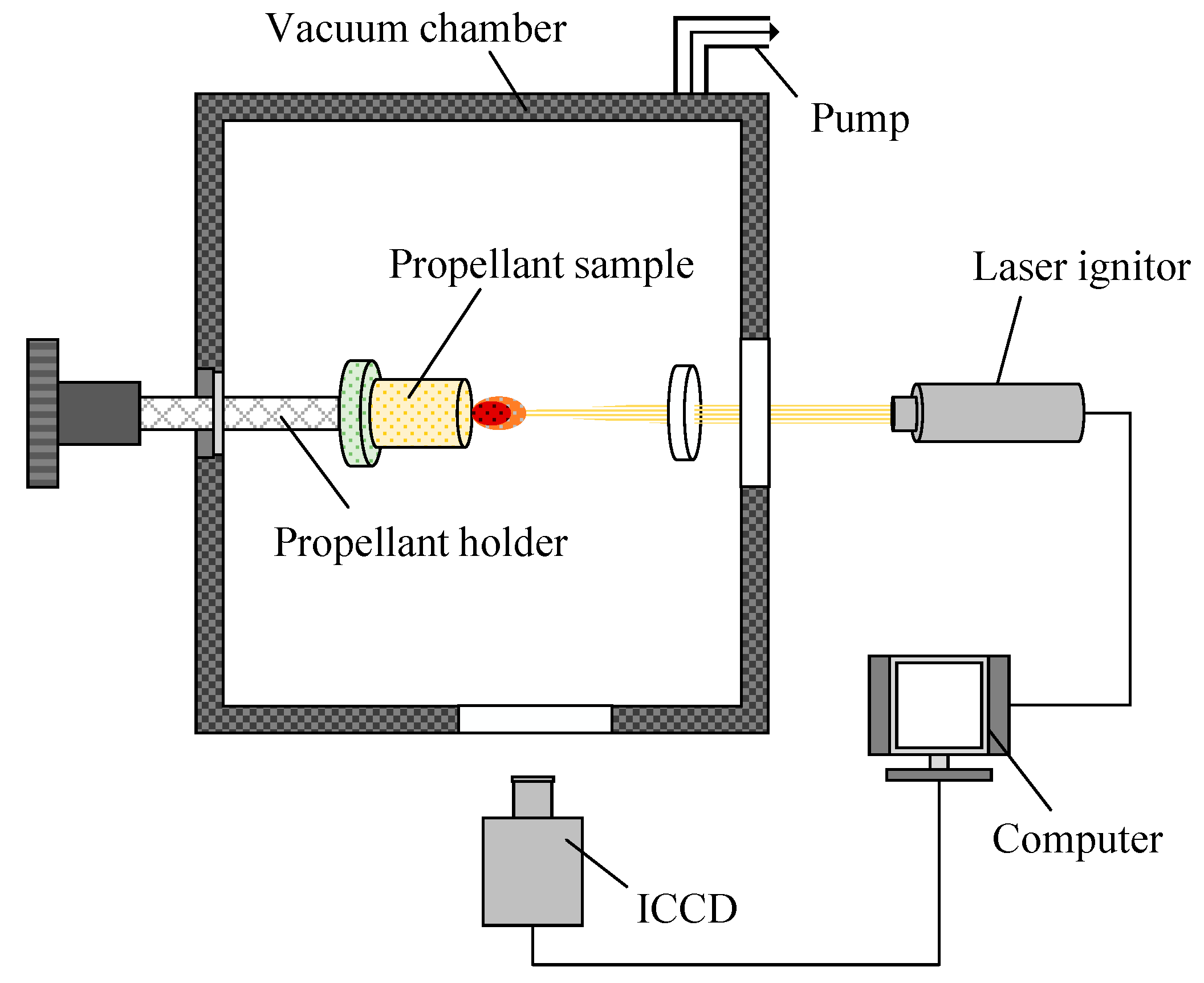
The experimental arrangement for the laser-ablation plume observation system is shown in Figure 2. The targets were mounted on a disk-shaped holder in a cylindrical vacuum chamber measuring 2.4 m in diameter and 3 m in length with a pumping system. A fiber laser was employed to generate a 5 ms pulsed laser with a wavelength of 1064 nm and an energy output of 5 J. The laser beam entered the vacuum chamber through a quartz glass window and was focused on the target surface by a convex lens with a focal length of 400 mm, resulting in a laser spot of approximately 0.8 mm in diameter. The dynamics of the plume were captured in the experiment using an ultra-high-speed intensified charge-coupled device (ICCD) camera (PCO DIMAX S4) with a fixed exposure time of 5.236 μs. The timing of the ICCD camera and the laser was regulated by an industrial computer. Furthermore, all test groups in our experiments were conducted at a background pressure of 5 × 10⁻⁴ Pa with other conditions being kept consistent.

2.2. Preparation of Doped Propellants

Previous research has suggested that PTFE filled with carbon additives can augment the performance of laser propulsion [33,34]. To elucidate the implications of carbon additives on plume dynamics, we employed PTFE powder as the substrate, and several carbon particles were chosen as additives to prepare composite propellants. Table 1 provides basic information about the substrate and additives.
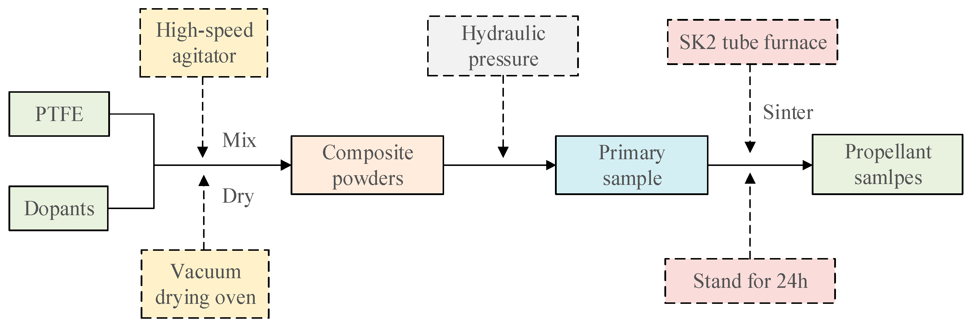
The composite propellant samples in the experiments were prepared under the same conditions via the sintering molding method as shown in Figure 3 [29]. The first step in the process was to incorporate the prepared carbon particles into the PTFE powder at a mass ratio of 5:95 and blend to homogeneity using a high-speed agitator (JYL-C50T) at 200 rpm. The mixture was placed in a vacuum drying oven at a constant temperature of 85 °C for an hour to remove moisture. Subsequently, the mixture was loaded into a specific mold, and a steady pressure of 20 MPa was applied for 20 min to obtain the initial samples, which were left to stand for 24 h to relieve any residual stress. In the next step, the samples were sintered using an SK2 tube furnace with a heating rate set to 50 °C/h, and argon was used as a shielding gas to isolate them from the air. Once the temperature reached 380 °C, it was maintained for 6 h to ensure an even mixing of the matrix and dopant. Following this, the tube furnace was gradually cooled to 327 °C at a rate of 50 °C/h. when the temperature reached 327 °C, it was held for 2 h to enhance the crystallinity of the sample. Finally, the tube furnace was shut down, and the argon gas was maintained until the temperature dropped to room temperature. From this sintering process, we produced a series of composite propellants doped with various carbon particles for the experiments.

2.3. Image Processing Method

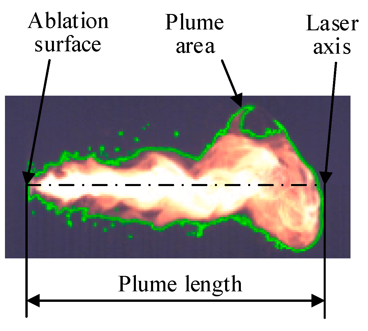
A series of time-dependent laser ablation plume images of the composite propellant were obtained using an established high-speed photogrammetry system. The plume features were extracted using an image segmentation method, as shown in Figure 4. We introduced the length, area, expansion rate, and relative luminosity of the plume to evaluate its characteristics. The plume length was defined as the extension of the plume front along the normal direction of the ablated surface. The plume area was the scaled luminous region in the plume image, and the expansion rate was the variation in displacement per second of the downstream plume. The relative luminosity referred to the ratio of the observed luminosity to the maximum luminosity.
To calculate the plume area, a binarization method was employed to distinguish the plume from the background. We first collected a large number of background images in the experimental environment and extracted the maximum grey value by greyscale transformation, which served as the ambient value. For each plume image, comprising a finite number of pixels, the presence of any plume in a region was determined by comparing the grey value of the pixel with the ambient grey value. Subsequently, the plume area was computed by accumulating all the pixels in the image with a grey value greater than the ambient value. Furthermore, the relative luminosity was obtained by calculating the ratio of the grey value in the plume region to its maximum value.
The aforementioned plume parameters are intimately concerned with the working performance of the propellant in LAPPTs. Variation in plume length as a function of time can directly reflect the expansion rate of the plume along the normal direction of the propellant surface. When the plume length exhibits a nearly linear increase, it indicates that the plume expansion rate is approaching a constant value. If there are abrupt changes or oscillations associated with the growth of the plume, then the generated plume is more volatile, which can also affect the discharge success rate of the thruster. The plume area can partially reflect the initial plume divergence. The larger the length-to-width ratio of the plume along the normal direction of the propellant surface, the smaller the diffusion rate in the non-principal propelling direction, which would help to improve propellant utilization. In addition, the higher the plume expansion rate, the larger the quantity of neutral gas that enters the discharge channel in a single pulsed discharge. This is also expected to augment propellant utilization, while the relative luminosity of the plume can partially reflect ionizability and electron density [35,36].

3. Results

3.1. Plume Images

Figure 5 shows the dynamic plume images of three carbon-doped composite propellants and pure PTFE. The plume evolution of the nano-carbon-doped composite propellant is shown in Figure 5a. When the laser was applied to the sample, it immediately generated a bright, rounded plume cluster on the ablation surface. As the ablation continued, this rounded plume cluster expanded and eventually split at ~300 μs, forming a jet and a large tail plume cluster emanating from the surface. However, the distribution of the jet and the plume cluster at the tail end was not uniform, and noticeable fractures were observed. Additionally, the tail plume cluster appeared dim and deflected downwards. At the end of a laser pulse, the jet gradually disappeared, while the tail plume cluster expanded and eventually dissipated.
Figure 5b shows the plume evolution of the graphite-doped composite propellant. Similar to the previous case, when the sample was subjected to laser ablation, a bright rounded plume cluster appeared on the ablation surface, expanding continuously. The difference was that this cluster split both upwards and downwards at ~600 μs, forming a larger plume cluster with relatively lower brightness. Simultaneously, a bright jet was generated on the ablation surface, with noticeable splash particles observed around it. As the ablation progressed, both the jet and large plume cluster spread outwards gradually, with the tail jet and plume cluster deflected upwards. The brightness at the tail end of the jet was unevenly distributed, but there were no observed fractures during the ablation. At the end of a laser pulse, the jet did not disappear immediately but slowly darkened until it vanished. The residual plume cluster continued to spread until it completely dissipated.
The plume evolution of the graphene-doped composite propellant is shown in Figure 5c. When the laser was irradiated at the propellant sample, a bright rounded plume cluster rapidly formed on the ablation surface, expanding continuously. However, this rounded plume cluster started to split at ~100 μs and deflect downwards. Similar to the previous two cases, the jet of the sample originated from the ablation surface, but its tail exhibited less uniformity with lower brightness. Nevertheless, the overall brightness level was higher than that of the former two cases. The tail plume cluster expanded throughout the ablation process, primarily distributed below the jet during the early stage and above the jet at the later stage of ablation. Bright particles were observed around the jet, including its tail. Additionally, a noticeable fracture appeared at the tail end of the jet during the late stage of ablation.
Figure 5d shows the plume evolution of the pure PTFE sample, it can be observed that the plume generated by laser ablation of PTFE was less pronounced when compared to composite propellants fabricated of PTFE filled with nano-carbon, graphite, and graphene, indicating that the presence of these carbon particles enhanced the interaction between the laser and the propellant due to their higher optical absorption coefficient compared to that of PTFE.

3.2. Plume Parameters

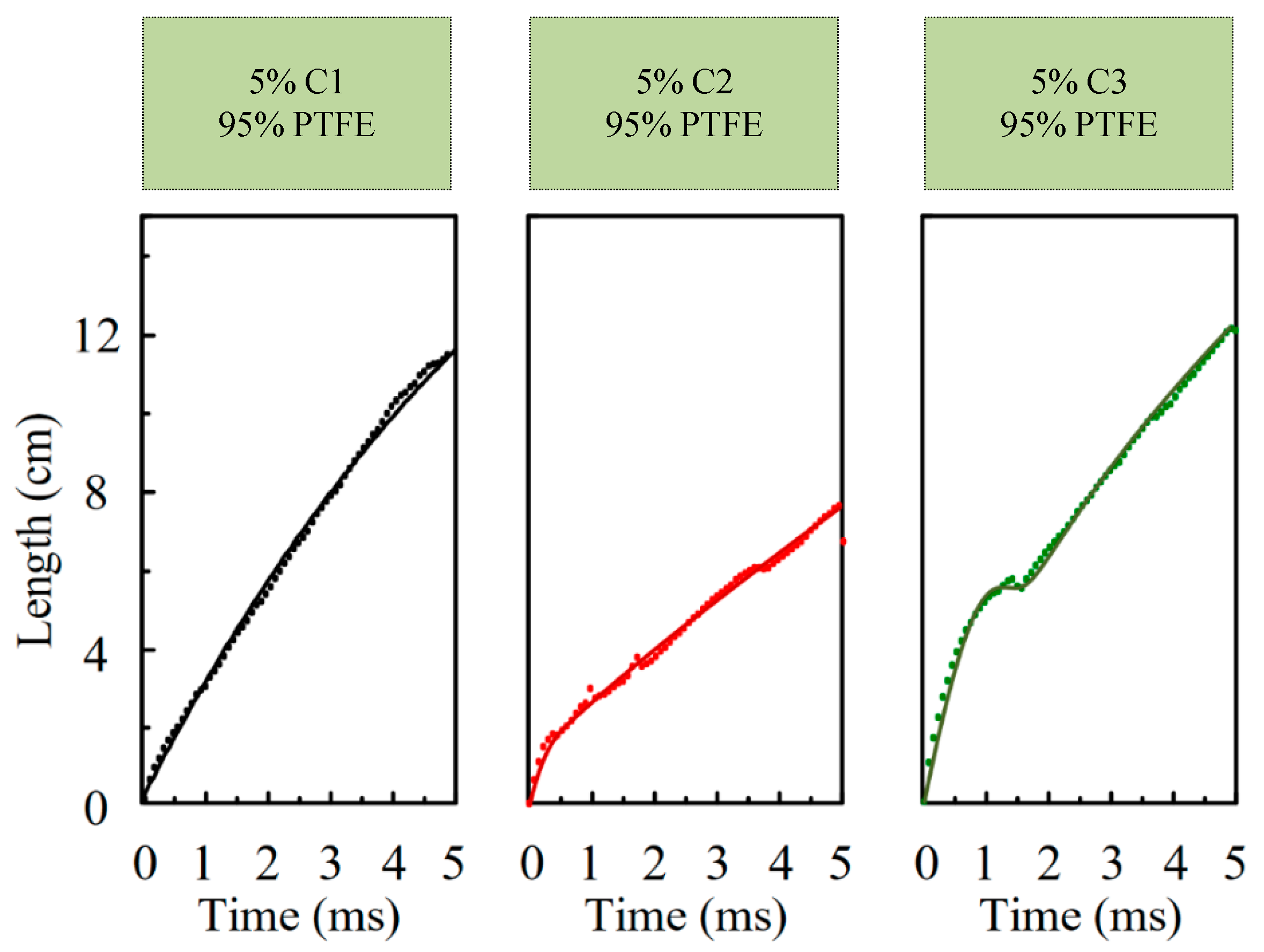
Figure 6 shows the fitting plot of plume length for carbon-doped composite propellants. It can be seen that three different composite propellant samples exhibited varying trends. The plume length of the nano-carbon-doped composite propellant sample presented approximately linear growth, as can also be seen in Figure 5a, indicating a consistently stable expansion rate. At the end of a laser pulse, the plume length reached a maximum of 11 cm, with a corresponding plume expansion rate of 22 m/s. The plume length of the graphite-doped composite propellant sample exhibited parabolic growth before the ablation time of 1 ms, as can also be observed in Figure 5b. Subsequently, it increased linearly to reach a maximum length of 8 cm. The average plume expansion rate was 16 m/s. Variation in the plume length of the graphene-doped composite propellant sample was similar to that of the graphite-doped composite propellant sample, as can also be seen in Figure 5c. It exhibited parabolic growth before the ablation time of 1.5 ms, followed by a nearly linear increase. The maximum length of its plume reached 12 cm, with an average expansion rate of 24 m/s.
After comparing the three sets of experiments, we can conclude that the plume length of carbon-doped composite propellant samples primarily displayed a linear growth, indicating a stable expansion rate of the plume, which further suggests that the addition of carbon particles had significantly enhanced the optical absorption coefficient of the PTFE. Of the three composite propellant samples, the graphene-doped one exhibited the greatest plume length and the highest expansion rate, primarily attributable to the higher melting point of graphene compared to nano-carbon powder and graphite, which is significantly greater than that for PTFE. When exposed to laser irradiation, the dispersed graphene in PTFE facilitated the deposition of laser energy, thereby intensifying ionization through reactions with the excited products of PTFE in the plume. Despite graphite having a higher melting point than nano-carbon powder, the graphite-doped composite propellant sample demonstrated the smallest plume length and expansion rate due to its flame retardancy.
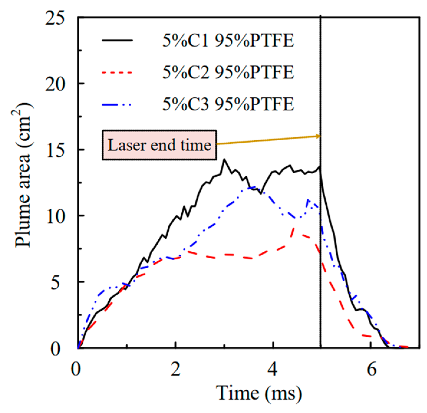
Figure 7 shows variation in the plume area of carbon-doped composite propellant samples. During the early ablation stage, the plume area continued to increase with time until it reached a certain value and then fluctuated around this level. For the nano-carbon-doped composite propellant sample, its plume area kept increasing to a maximum of 15 cm2, before 3 ms and then remained dynamically stable until the end of the laser pulse width. As for the graphite-doped composite propellant sample, its plume area continued to increase before 2 ms and then remained constant at 7 cm2 until the end of the laser pulse width. In the case of the graphene-doped composite propellant sample, the area kept increasing until 3.5 ms, after which it fluctuated and stabilized at 10 cm2. Once the laser stopped irradiating the propellant, although the plume area of three composite propellant samples was unequal, they all took roughly the same time to decrease to 0. Throughout the ablation process, the plume area of the nano-carbon-doped composite propellant sample was the greatest, followed by that of the graphene-doped sample. The plume area of the graphite-doped composite propellant sample was the smallest.
Based on the analysis of the plume images, it was observed that the jet of the carbon-doped composite propellant sample continued to spread during the ablation process but the plume cluster at the tail end gradually darkened and eventually vanished. In the case of tradeoffs, there was no significant increase in the plume area at the late stage of the ablation. The disappearance of the plume cluster at the tail end suggested that the ablation plume diverged at small angles, and a majority of particles maintained forward velocity, suggesting that more mass can reach the discharge channel during a pulsed discharge and is expected to achieve better performance in electromagnetic acceleration.
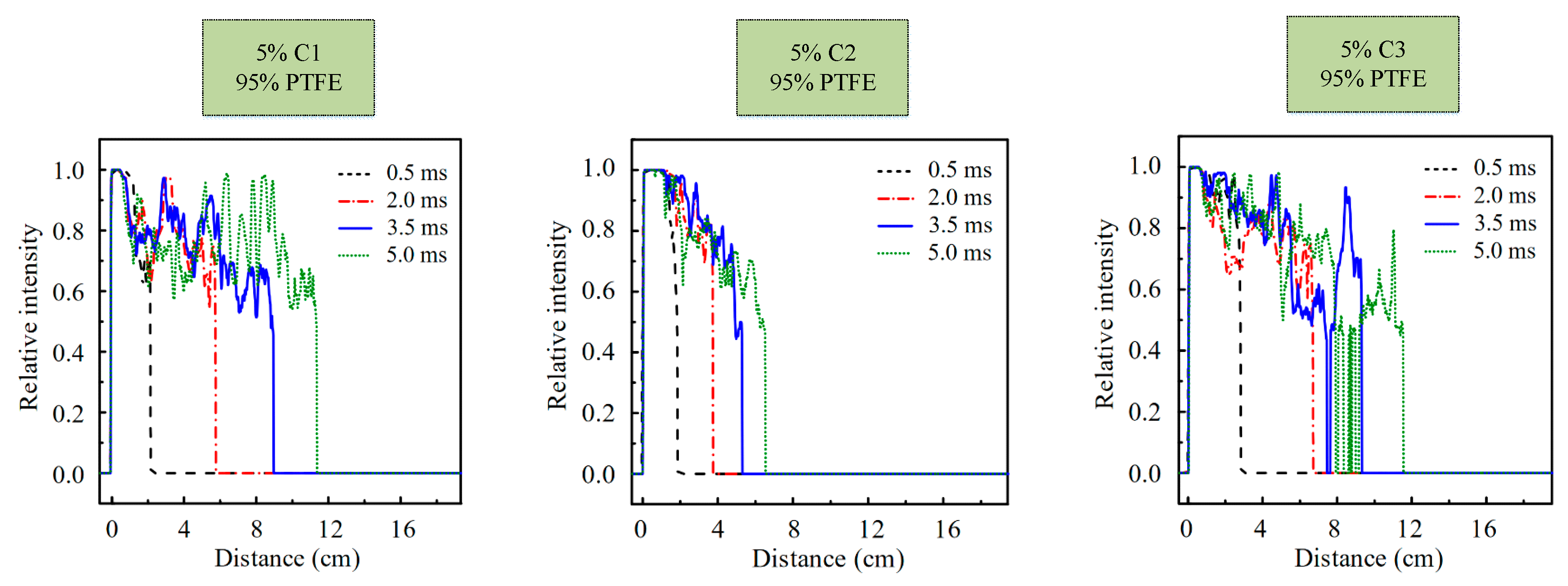
Figure 8 shows the normalized plume relative luminosity of the axis distribution for the carbon-doped composite propellant samples. The maximum relative luminosity of the plume generated by laser ablation of the nano-carbon-doped composite propellant sample was observed within a range of 0–1 cm from the ablation surface. As the distance from the ablation surface increased, the relative luminosity fluctuated, but it consistently remained above 0.5 throughout the laser duration. For the graphite-doped composite propellant sample, the maximum relative luminosity of the plume was observed within the range of 0–2 cm from the ablation surface. Beyond this distance, the relative luminosity gradually decreased. Furthermore, the area exhibiting a relative luminosity greater than 0.5 was smaller compared to that of the nano-carbon-doped composite propellant sample. As for the graphene-doped composite propellant sample, the maximum relative luminosity of the plume consistently appeared within the range of 0–0.5 cm from the ablation surface. As the distance from the ablation surface increased, the relative luminosity decreased. Additionally, noticeable fractures in the plume were observed at the late stage of ablation, and there were multiple discontinuous areas after 3.5 ms.
As mentioned before, the doped graphene facilitated ionization of the plume through reactions with the initiated products of PTFE. The optical emission in a vacuum arose from the excitation with ambient gases and the impact excitation of electrons, with the latter being the dominant factor [37]. This also explains why graphite-doped composite propellant generated a plume with a maximum relative luminosity closest to the ablated surface, followed by nano-carbon, and lastly, graphite. The increasing radiative emission over time was consistent with the deceleration of the plume as a consequence of the kinetic energy conversion. As the distance from the ablation surface increased, electron collision-induced radiation gradually superseded the chemical reaction, and the luminosity of the plume gradually diminished as the plasma density decreased.

3.3. Graphene Fraction Dependence of Plume Characteristics

Compared to the composite propellant sample doped with nano-carbon and graphite, the graphene-doped composite propellant sample exhibited a higher plume expansion rate and a smaller plume divergence angle. Therefore, the graphene-doped samples were chosen for further investigation into the impact of the doping ratio on plume characteristics.
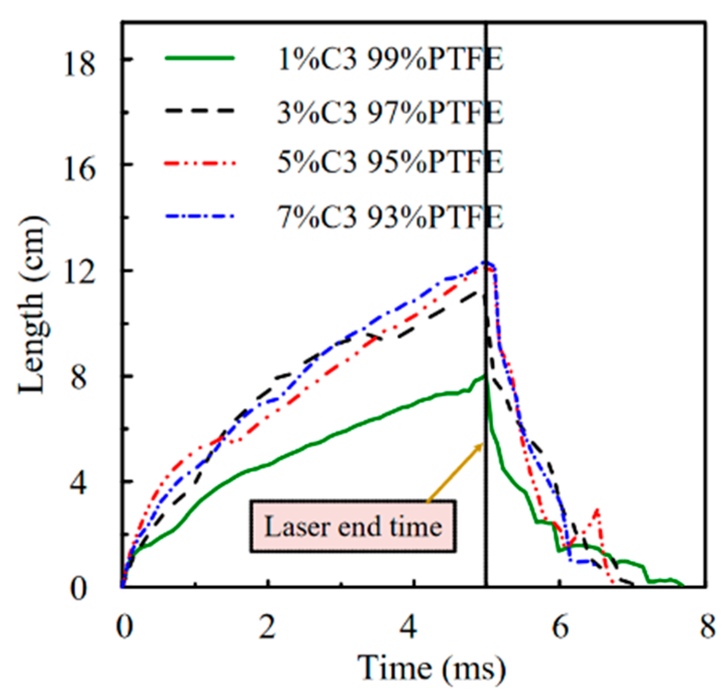
Figure 9 shows the dependence of plume length on the graphene doping ratios. It can be seen from the figure that the plume length of all composite propellant samples followed similar trends. Initially, it increased with the ablation time and then reached a maximum in an approximately linear manner. The composite propellant sample with higher doping ratios exhibited a greater plume length and a higher expansion rate. However, once the doping ratio exceeded 3%, the increment resulting from increasing the doping ratio became relatively small. Based on the order of doping ratios (from low to high), the maximum plume lengths of the graphene-doped composite propellant samples were 8, 11, 12, and 12.5 cm, respectively. The average plume expansion rates were 16, 22, 24, and 25 m/s, respectively. At the end of a laser pulse, the plume length gradually decreased. Nevertheless, the composite propellant samples with higher doping ratios decreased to 0 faster than those with lower doping ratios.
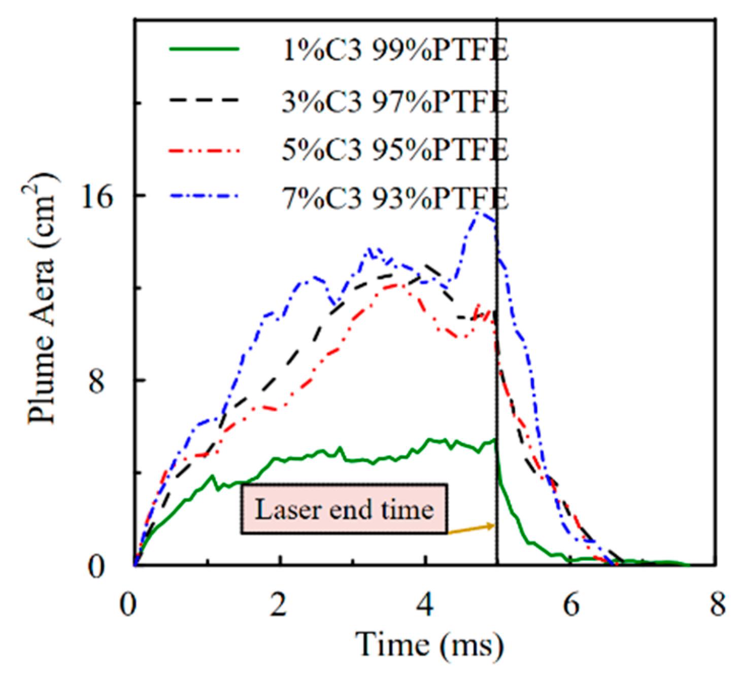
Figure 10 shows the variations in the plume area of graphene-doped composite propellant samples with different doping ratios. The plume area of the composite propellant sample with a 1% doping ratio continuously increased to 4 cm2 before 1 ms and then remained stable until the end of laser ablation, whereas the plume area of the composite propellant sample with a 7% doping ratio kept increasing until it reached a maximum of 16 cm2 with slight fluctuations observed at 2–5 ms. As for the composite propellant samples with doping ratios of 3 and 5%, they displayed nearly identical changes in the plume area, but the area of the former consistently remained the larger.
As mentioned above, increasing the doping ratio of graphene promoted an increase in the plume length, expansion rate, and area of propellant samples due to the promising effect of graphene in promoting light absorption of PTFE. However, once the doping ratio surpassed 3%, improvement brought by the increase was insignificant. Considering the plume divergence angle and expansion rate, 5% remained the optimal doping ratio for the graphene-doped composite propellant sample.

4. Conclusions

In the present work, the plume characteristics of PTFE doped with various carbon particles under laser irradiation were analyzed to find the preferred dopant for the fabrication of the composite propellant. The dynamic plume was captured using a high-speed photogrammetry system and the plume parameters were extracted via an image binarization method. In addition, the preferred dopant was further qualitatively analyzed to determine the effect of the doping ratio on the plume parameters. The main conclusions are as follows:
A comparison of parameters determined that the plume quality produced by the composite propellant fabricated from PTFE filled with various carbon particles was better than that of pure PTFE. The carbon-doped composite propellants produce a jet of diminishing luminance as the plume grew under laser stimulation, in which the tail was less homogeneous as reflected in a large plume cluster of dimmer brightness and progressively vanishing. Moreover, the ablated plume area of the carbon-doped composite propellants did not present sustained growth as a function of time but remained dynamically stable after it reached a certain value. Of these composite propellants, the graphene-doped one exhibited the largest plume length and expansion rate, but a smaller plume area compared to the nano-carbon-doped propellant. When further analyzing the effect of graphene doping ratio on the parameters of the plume generated by the composite propellant, we found that increasing the doping ratio promoted the growth of plume length, expansion rate, and area, with the optimal doping ratio of ~5% being obtained, though the enhanced result was not obvious when the doping ratio was greater than 3%.

Author Contributions

Writing—original draft preparation, Y.L.; writing—review and editing, Y.O.; project administration, J.W.; supervision, Y.Z. All authors have read and agreed to the published version of the manuscript.

Funding

This research was funded by the Innovative Research Group Project of the National Natural Science Foundation of China, grant number T2221002.

Institutional Review Board Statement

Not applicable.

Informed Consent Statement

Not applicable.

Data Availability Statement

The data that support the findings of this study are available from the corresponding author upon reasonable request.

Conflicts of Interest

The authors declare no conflict of interest.

References

  1. Levchenko, I.; Bazaka, K.; Mazouffre, S.; Xu, S. Prospects and Physical Mechanisms for Photonic Space Propulsion. Nat. Photon. 2018, 12, 649–657. [Google Scholar] [CrossRef]
  2. Ou, Y.; Zhang, Y.; Wu, J.; Li, J.; Tan, S.; Zhao, Y. Comparative Study of PTFE Filled Different Dopants as Propellants for Laser-Electric Hybrid Thruster. Acta Astronaut. 2021, 183, 199–210. [Google Scholar] [CrossRef]
  3. Yu, H.; Li, Y.; Ji, Y.; Wu, X.; Yuan, Y.; Li, H.; Yang, J. The Propulsion Mechanism and Tiny Particles Removal Investigation Based on the “Micro-Gun” Propulsion System. Opt. Laser Technol. 2019, 119, 105627. [Google Scholar] [CrossRef]
  4. Gurin, A.V.; Kuvaev, K.Y.; Loktionov, E.Y.; Protasov, Y.S.; Sirenko, K.N.; Zakharov, V.I. First Attempt of a Laser Thruster Space Flight Test: Lost at Launch. Opt. Laser Technol. 2019, 120, 105656. [Google Scholar] [CrossRef]
  5. Wu, Z.; Huang, T.; Liu, X.; Ling, W.Y.L.; Wang, N.; Ji, L. Application and Development of the Pulsed Plasma Thruster. Plasma Sci. Technol. 2020, 22, 094014. [Google Scholar] [CrossRef]
  6. Liu, H.; Niu, X.; Li, X.; Lu, H. Reviews on Electrical Propulsion Technology Using Iodine Alternatives. J. Propuls. Technol. 2019, 40, 12–25. [Google Scholar] [CrossRef]
  7. Dietz, P.; Gärtner, W.; Koch, Q.; Köhler, P.E.; Teng, Y.; Schreiner, P.R.; Holste, K.; Klar, P.J. Molecular Propellants for Ion Thrusters. Plasma Sources Sci. Technol. 2019, 28, 084001. [Google Scholar] [CrossRef]
  8. Ou, Y.; Wu, J.; Zhang, Y. Design and Experimental Results of a Laser-Ignited Solid-Propellant-Fed Magnetoplasmadynamic Thruster. Rev. Sci. Instrum. 2020, 91, 074501. [Google Scholar] [CrossRef]
  9. Ou, Y.; Wu, J.; Zhang, Y.; Li, J.; Tan, S. Theoretical Modeling and Parameter Analysis of Micro-Pulsed Plasma Thruster. Energies 2018, 11, 1146. [Google Scholar] [CrossRef]
  10. Kamimura, T.; Tahara, H. R&D, Launch and Initial Operation of the Osaka Institute of Technology 1st PROITERES Nano-Satellite with Electrothermal Pulsed Plasma Thrusters and Development of the 2nd and 3rd Satellites. In Proceedings of the 50th AIAA/ASME/SAE/ASEE Joint Propulsion Conference; American Institute of Aeronautics and Astronautics, Cleveland, OH, USA, 28 July 2014. [Google Scholar]
  11. Manente, M.; Trezzolani, F.; Magarotto, M.; Fantino, E.; Selmo, A.; Bellomo, N.; Toson, E.; Pavarin, D. REGULUS: A Propulsion Platform to Boost Small Satellite Missions. Acta Astronaut. 2019, 157, 241–249. [Google Scholar] [CrossRef]
  12. Kim, D.; Jerjen, H.; Geha, M.; Chiti, A.; Milone, A.P.; Costa, G.D.; Mackey, D.; Frebel, A.; Conn, B. Portrait of a Dark Horse: A Photometric and Spectroscopic Study of the Ultra-Faint Milky Way Satellite Pegasus III. Astrophys. J. 2016, 833, 16. [Google Scholar] [CrossRef]
  13. Li, Y.; Dai, J.; Zhao, C.; Zhang, S. Research on Rapid Batch Test of Whole Star Based on Pulsating Production Line. J. Phys. Conf. Ser. 2022, 2252, 012015. [Google Scholar] [CrossRef]
  14. Lev, D.; Myers, R.M.; Lemmer, K.M.; Kolbeck, J.; Koizumi, H.; Polzin, K. The Technological and Commercial Expansion of Electric Propulsion. Acta Astronaut. 2019, 159, 213–227. [Google Scholar] [CrossRef]
  15. Huang, T.; Wu, Z.; Sun, G.; Liu, X.; Ling, W.Y.L. Study and Modeling of Propellant Ablation in Coaxial Ablative Pulsed Plasma Thrusters. Acta Astronaut. 2020, 173, 69–75. [Google Scholar] [CrossRef]
  16. Ling, W.Y.L.; Schönherr, T.; Koizumi, H. Characteristics of a Non-Volatile Liquid Propellant in Liquid-Fed Ablative Pulsed Plasma Thrusters. J. Appl. Phys. 2017, 121, 073301. [Google Scholar] [CrossRef]
  17. Ziemer, J.; Cubbin, E.; Choueiri, E.; Birx, D.; Ziemer, J.; Cubbin, E.; Choueiri, E.; Birx, D. Performance Characterization of a High Efficiency Gas-Fed Pulsed Plasma Thruster. In Proceedings of the 33rd Joint Propulsion Conference and Exhibit; American Institute of Aeronautics and Astronautics, Seattle, WA, USA, 6 July 1997. [Google Scholar]
  18. Ling, W.Y.L.; Zhang, S.; Fu, H.; Huang, M.; Quansah, J.; Liu, X.; Wang, N. A Brief Review of Alternative Propellants and Requirements for Pulsed Plasma Thrusters in Micropropulsion Applications. Chin. J. Aeronaut. 2020, 33, 2999–3010. [Google Scholar] [CrossRef]
  19. Zhao, Y.; Tan, S.; Wu, J.; Zhang, Y.; Ou, Y.; Zheng, P. The Ablation Characteristics of Laser-Assisted Pulsed Plasma Thruster with Metal Propellant. Plasma Sci. Technol. 2021, 23, 104007. [Google Scholar] [CrossRef]
  20. Yu, H.; Li, H.; Wang, Y.; Cui, L.; Liu, S.; Yang, J. Brief Review on Pulse Laser Propulsion. Opt. Laser Technol. 2018, 100, 57–74. [Google Scholar] [CrossRef]
  21. Ou, Y.; Wu, J.; Zhang, Y.; Li, J. Modeling the Laser-Polymer Interaction of Laser Propulsion Systems Considering Progressive Surface Removal, Thermal Decomposition and Non-Fourier Effect. Acta Astronaut. 2021, 186, 319–328. [Google Scholar] [CrossRef]
  22. Ou, Y.; Wu, J.; Zhang, Y.; Li, J. Comparative Study of Plume Characteristics of Polymeric Propellants Filled with Different Oxides for Laser-Electric Hybrid Thruster. Opt. Laser Technol. 2022, 147, 107609. [Google Scholar] [CrossRef]
  23. Ou, Y.; Wu, J.; Du, X.; Zhang, H.; He, Z. Experimental Investigation on Characteristics of Pulsed Plasma Thrusters with the Propellant Samples of Modified PTFE Filled Si, Al and Al2O3. Vacuum 2019, 165, 163–171. [Google Scholar] [CrossRef]
  24. Zhang, H.; Duan, B.; Wu, L.; Hua, Z.; Bao, Z.; Guo, N.; Ye, Y.; Galfetti, L.; DeLuca, L.T.; Shen, R. Actualization of an Efficient Throttleable Laser Propulsion Mode. Energy 2021, 221, 119870. [Google Scholar] [CrossRef]
  25. Ding, T.; Guo, W.; Cao, W.; Pei, H.; Zheng, X.; Liu, C. Experimental Study of Reaction Properties of Aluminum/Polytetrafluoroethylene Powder under Laser Ablation. AIP Adv. 2021, 11, 085010. [Google Scholar] [CrossRef]
  26. Küper, S.; Stuke, M. Ablation of Polytetrafluoroethylene (Teflon) with Femtosecond UV Excimer Laser Pulses. Appl. Phys. Lett. 1989, 54, 4–6. [Google Scholar] [CrossRef]
  27. Mitra, A.; Thareja, R.K. Determination of Laser Ablation Threshold of Teflon at Different Harmonics of Nd:YAG Laser Using Photothermal Deflection Technique. J. Mater. Sci. 1999, 34, 615–619. [Google Scholar]
  28. Zhang, Y. Theoretical and Experimental Investigation on the Property of Propellant Ablation and Propulsion Performance of Laser Ablation Magnetoplasmadynamic Thruster. Ph.D. Thesis, National University of Defense Technology, Changsha, China, 2018. [Google Scholar]
  29. Tan, S.; Wang, M.; Wu, J.; Zhang, Y.; Li, J. A Study on the Plasma Plume Expansion Dynamics of Nanosecond Laser Ablating Al/PTFE. Energies 2020, 13, 3321. [Google Scholar]
  30. Duan, B.; Zhang, H.; Hua, Z.; Wu, L.; Bao, Z.; Guo, N.; Ye, Y.; Shen, R. Impulse and Electric Charge Characteristics of Chemical Propellant under Pulsed Laser Irradiation. Vacuum 2021, 192, 110419. [Google Scholar] [CrossRef]
  31. Ou, Y.; Wu, J.; Zhang, Y.; Li, J.; Zhao, Y. Plume Characteristics of Polymeric Material Doped with Different Metal Particles under Pulsed Laser Irradiation. Opt. Laser Technol. 2022, 152, 108132. [Google Scholar] [CrossRef]
  32. Ou, Y.; Wu, J.; Zhang, Y. Effects of Carbon, Graphite, and Graphene as Propellant Dopants in a Laser-Electric Hybrid Acceleration System. Opt. Laser Technol. 2022, 151, 108007. [Google Scholar] [CrossRef]
  33. Sinko, J.E.; Pakhomov, A.V.; Millen, S.; Zhu, J.; Sinko, R.J.; Potts, K.; Pakhomov, A.V. Delrin® for Propulsion with CO2 Laser: Carbon Doping Effects. AIP Conference Proceedings; AIP: Kailua-Kona, HI, USA, 2008; Volume 997, pp. 254–265. [Google Scholar]
  34. Pakhomov, A.V.; Mahaffy, K.E.; Pakhomov, A.V. Binary Solid Propellants for Constant Momentum Missions. AIP Conference Proceedings; AIP: Kailua-Kona, HI, USA, 2008; Volume 997, pp. 266–279. [Google Scholar]
  35. Wei, L.-Q.; Li, W.-B.; Ding, Y.-J.; Zhu, X.-M.; Wang, Y.-F.; Hu, J.-F.; Yan, S.-L.; Yu, D.-R. A Photographic Method for In-Orbit Measurement of Electron Temperature Distribution in the Plume of Hall Thrusters. Plasma Sources Sci. Technol. 2018, 27, 084002. [Google Scholar] [CrossRef]
  36. Han, X.; Wang, Y.; Chen, Z.; Wang, Y.; Wu, J.; Li, Z.; Tang, H.; Cao, J. High-Resolution Particle Density Measurement for Argon Plasma Plume by Image Reconstruction and Collisional-Radiative Model. Opt. Laser Technol. 2023, 167, 109544. [Google Scholar] [CrossRef]
  37. Kumar, A.; Singh, R.K.; Subramanian, K.P.; Patel, B.G.; Sunil, S.; Prajapati, I.A. Effects of Ambient Pressure and Laser Fluence on the Temporal Evolution of 426.7 Nm CII Line in Laser-Blow-off of Multilayered LiF-C Thin Film. J. Phys. D Appl. Phys. 2006, 39, 4860–4866. [Google Scholar] [CrossRef]
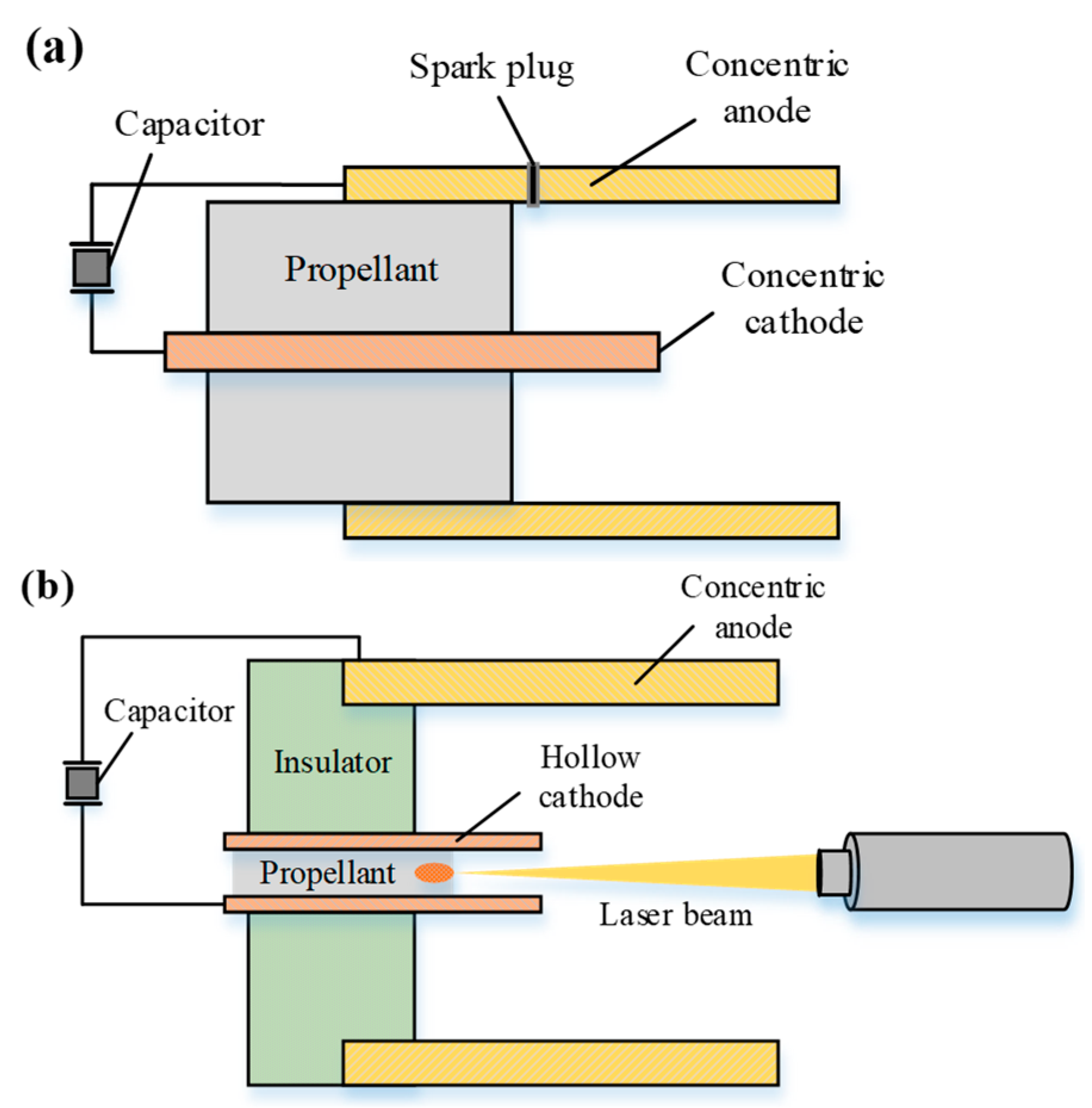
Figure 1. Schematics of PPT, (a) coaxial PPT and (b) laser-assisted (LA) PPT.
Applsci 13 09283 g001
Figure 2. Schematic of the experimental system.
Applsci 13 09283 g002
Figure 3. Preparation of composite propellant samples.
Applsci 13 09283 g003
Figure 4. Plume feature extraction.
Applsci 13 09283 g004
Figure 5. Plume images of different propellant formulas.
Applsci 13 09283 g005
Figure 6. Plume lengths of different carbon-doped composite propellant samples.
Applsci 13 09283 g006
Figure 7. Plume areas of different carbon-doped composite propellant samples.
Applsci 13 09283 g007
Figure 8. Normalized relative luminosity of the axis distribution.
Applsci 13 09283 g008
Figure 9. Plume lengths of composite propellants with different graphene doping ratios.
Applsci 13 09283 g009
Figure 10. Plume areas of composite propellants with different graphene doping ratios.
Applsci 13 09283 g010
Table 1. Carbon additives and PTFE substrate information.
MaterialsSizeCompanyColorMelting Point
Nano-carbon powder (C1)30 nmBeijing DknanoBlack3830 K
Graphite powder (C2)30 nmBeijing DknanoBlack3925 K
Graphene powder (C3)1.2 nmBeijing DknanoBlack4125 K
PTFE powder25 μmAmerican 3MWhite600 K
Disclaimer/Publisher’s Note: The statements, opinions and data contained in all publications are solely those of the individual author(s) and contributor(s) and not of MDPI and/or the editor(s). MDPI and/or the editor(s) disclaim responsibility for any injury to people or property resulting from any ideas, methods, instructions or products referred to in the content.