Abstract
Free space optics (FSO)-based optical body area networks (OBANs) are receiving massive attention as an opportunity to address the limitations of their radio frequency (RF)-based counterparts. This boom in research interests is primarily due to multitude of benefits, including high capacity, immunity to electromagnetic interference (EMI), rapid installation, cost efficiency, and license-free use of spectrum. Securing the transmission of patient health data against interception in OBANs using insecure FSO channels is a challenging task. Therefore, we propose a low-cost, flexible, and secure OBAN based on FSO technology and a time-delayed two dimensional (2D) spectral/spatial optical code-division multiple access (OCDMA) system. The proposed architecture consists of eight sensors attached to the bodies of patients. The sensors operate at a rate of 50 kbps. Electrical data generated from each sensor are used to modulate an optical carrier and then encoded using 2D-spectral/spatial double weight–zero cross correlation (DW-ZCC) code. The 2D encoded optical signals are then time delayed to eliminate the multiple parallel FSO channels between the transmitter and medical center. The combined optical signal consists of eight 2D-encoded time-delayed optical signals transmitted towards a remote medical center over an FSO channel with a range of 1 km. The received signal is decoded and the data from each sensor are recovered after photodetection at the medical center for further analysis. The overall performance of the sensors is analyzed using bit-error rate (BER) and quality factor (Q-factor) plots for different weather conditions and lengths of the FSO channel, considering the log-normal channel model. The capital expenditure (CAPEX) of the proposed architecture is analyzed and compared with the conventional 2D-spectral/spatial FSO system to determine the overall impact of introducing time delay units on the cost of implementation.
1. Introduction
A body area network (BAN), sometimes called a wireless body area network (WBAN), is a network of miniature battery-powered intelligent medical sensors equipped with wireless transmitters, which may be embedded inside the body as implants or mounted on the surface of the body [1,2]. These sensors usually provide continuous real-time localized or remote health monitoring for medical staff via recording or transmission of physiological data [2]. Typically, the communication link in a BAN may be categorized as intra-body or extra-body [3]. The former type refers to communication between sensors or between sensors and a coordinating device located on the same body, while the latter involves additional communication between sensors located on the body and a remote medical center or personal device via the coordinator [3,4]. The growth in aged population has increased health spending significantly owing to higher global demand for medical treatment and long-term nursing. Moreover, various infectious pandemics have further elevated health expenditures, pushing professionals to seek technology-oriented and cost-efficient solutions. U.S. healthcare spending was USD 4.3 trillion in 2021, or USD 12,914 per person, and accounted for 18.3% of GDP [5]. While this was less than the unprecedented 19.7% of the GDP in 2020 due to the COVID-19 pandemic, it is higher than 17.6% in 2019 and 2018. It is projected that health expenditures will grow at a rate of 5.1% per year over 2021–2030 [5]. E-health and telemedicine solutions are gaining popularity and being rapidly implemented globally, especially after the outbreak of COVID-19 pandemic, as a means to improve quality of life while reducing health budgets. Therefore, BANs are becoming acknowledged as a major constituent of e-health systems that allows sensing and timely transmission of patients’ physiological data from several medical sensors to remotely located medical staff [6]. In this way, the workload and required number of clinical staff can be reduced using e-health solutions, resulting in higher efficiency on the part of medical staff and reduced healthcare expenditures.
BANs were first regulated by Task Group IEEE 802.15.6, and a relevant standard based on RF technology was published in 2012 [7]. This standard was stipulated based on a wireless channel model obtained through measurements. Later, it was found that prolonged RF exposure may result in the malfunctioning of medical equipment and even damage the health of patients and medical staff [8]. Therefore, it is envisioned by experts that future BANs should have high throughput while being compatible with the green radio (GR) trend, resistive to EMI, utilize license-free spectrum, and have low installation and maintenance costs, among other requirements [2]. These intended features have recently been realized by integrating BAN and FSO, with the resulting technology being termed OBAN [9]. The intra-body or extra-body communication in OBANs is enabled through light beams in visible or IR range that are modulated with medical sensors data. OBAN is a relatively recent research field; therefore, abundant published work is not yet available. Works related to OBAN published over the past decade include [2,4,6,8,10,11,12,13,14,15,16,17]. Mirza et al. proposed secure OBAN architectures based on spectral amplitude coding–OCDMA (SAC-OCDMA) [2] and optical chaos [8]. Dhatchayeny et al. proposed OBANs based on visible light communication (VLC) enabled through a mobile phone camera [4] and via orthogonal spreading codes [10], and discussed patient mobility models [11]. Haddad et al. proposed FSO channel characterization and performance analysis with patient mobility [6], an intra-OBAN channel modelling and multiple access scheme [12], and channel modelling between sensors and a coordinator [13]. Chevalier et al. proposed channel modelling for a diffused optical channel between on-body sensors [14] and a star OBAN topology based on a diffused optical channel and spreading codes [15]. Hasan et al. proposed uplink transmission between medical sensors and a coordinator based on OCDMA [16] and OFDMA [17]. It is evident from the above discussion that most of the works published to date discuss channel modelling, patient mobility, and multiple access schemes. Schemes for secure transmission of sensor data over FSO channels have not been proposed in literature except in [2,8].
FSO systems can offer huge bandwidth, cost efficiency due to reduced deployment and maintenance costs, license-free spectrum usage, protection from EMI, environmental friendliness, and high inherent security compared to RF links [18]. However, outdoor FSO channels between the coordinator and medical center are highly vulnerable to problems such as atmospheric attenuation and turbulence, pointing errors, and eavesdroping [19]. An attacker can intercept the classified information of patients transmitted over FSO channels with little effort using simple means such as a wiretap installed in close proximity to the receiver [20], a receiver placed inside the divergence region of the beam [21], etc. Therefore, the probability of interception should be minimized by adopting effective means to enable the secure transmission of classified patient data over FSO channels using OBANs. The security of the OBANs has proven to be one of their most crucial design constraints. Various hardware based techniques have been reported exploiting optical chaos, pulse position modulation (PPM), quantum communication, and OCDMA for data security in OBANs from interception. Past works have proposed approaches on optical chaos [22,23,24,25], PPM [19], quantum communication [26,27], and OCDMA [2,28,29]. Encryption technologies based on optical chaos, quantum communication, and PPM usually provide good data security; however, they face issues around chaos synchronization, quantum entanglement, and the need to synchronize pulses in order to operate the timing circuits in the receiver, respectively [30]. Moreover, the implementation of these hardware-based techniques increases the overall cost and complexity of the system [30].
OCDMA is another secure communication technology that has been widely adopted to achieve absolute data privacy based on spreading the spectrum of the desired optical signal [2,30]. Apart from the intended function of data security, OCDMA systems provide ease of implemenation, cost-efficiency, robustness in transmission, and cancellation of different adverse effects between the transmitter and receiver, such as multiple access interference (MAI) and phase induced intensity noise (PIIN) [2,31]. The working principle of OCDMA systems is based on the conversion of zeros and ones into spectral domain as per the designed code by allowing or blocking required data bits by employing a specific setup of optical filters, splitters, and couplers on the encoder side; the information is then retrieved using a specific arrangement of optical filters, splitters, and couplers on the decoder side [31]. The codes used in OCDMA systems are typically of two types, called zero cross correlation (ZCC) and fixed in-phase cross-correlation codes [2]. This basic property of the codes is further exploited to create one-dimensional (1D), two-dimensional (2D), and three-dimensional (3D) OCDMA codes using the temporal, spatial, spectral, and polarization characteristics of signals [32]. Spectral/spatial combinations are most frequently used, leading to the development of various 2D codes for OCDMA systems [32]. To the best of our knowledge, no 2D OCDMA codes have been specifically designed to support OBANs. Nevertheless, owing to the efficient performance of the OCDMA family and their ability to cancel MAI, various 2D variants have been designed by combining 1D OCDMA codes. Khadim et al. developed 2D multidiagonal (MD) codes by applying ZCC 1D MD codes [33]. However, binary ones in the MD code are not placed adjacent to one another, which increases the code length as more users are added to the network. Furthermore, nonadjacent placement increases the complexity of the code along with the design of encoder and decoder modules. Matem et al. utilized a combination of 1D ZCC and MD codes to develop a 2D hybrid ZCC/MD code [34]. However, ZCC code employes code sequences with , which places an upper bound on the total number of users, as the code length is proportional to the weight of the code. Furthermore, both codes have nonadjacent placement of binary ones. Yousif et al. presented a 2D permutation vector (PV) code developed with the help of 1D PV code [35]. Each code is characterized by length, weight, and cross-correlation properties such that the length of the code depends on the number of users and the weight of the code. One of the drawbacks associated with this code is the limited number of code patterns that can be developed while maintaining the basic code properties. Furthermore, with a few exceptions, most such codes are developed with nonadjacent placement of ones. Sharma et al. proposed a 2D code sequence utilizing the 1D balanced incomplete block design (BIBD) technique [36]. The proposed code employs 2D BIBD blocks with an inherent cross-correlation property of . Furthermore, the weight of each sequence is kept as . Consequently, the length of the codewords needs to be kept long in order to reduce MAI, which in turn reduces the number of users and complicates the overall design of the system. Najjar et al. proposed another code that utilizes the diagonal eigenvalue unity (DEU) to develop a 2D-spectral/spatial coding scheme [37]. However, the DEU code is developed with , which requires a relatively complex receiver structure to overcome the MAI. Ammar et al. designed another code using the polarization technique to increase the cardinality of the system [38]. Their technique does not compress the OCDMA code. This is because polarization is applied for each user, which is not efficient for a higher number of users. Here, we report a flexible and secure OBAN of eight sensors based on FSO technology and 2D-spectral/spatial OCDMA. The sensors are distributed on the bodies of patients, and operate at the rate of 50 kbps. A 2D-spectral/spatial DW-ZCC code is used to encode the data on the transmitter side, and the combined optical signal is transmitted over a 1 km FSO channel towards the medical center. The time-delay technique is used to eliminate multiple parallel FSO paths between the transmitter and medical center. The combined signal is decoded and the data of each sensor are recovered after photodetection at the medical center. The performance of the sensors is analyzed using BER and Q-factor plots for different weather conditions considering the log-normal channel model. Based on the above proposal, the main contributions of this work are:
- A flexible, low-cost, and secure OBAN consisting of eight medical sensors operating at the rate of 50 kbps.
- A 2D-spectral/spatial DW-ZCC code for encoding the sensor data.
- Time-delay in 2D encoded signals to eliminate multiple parallel FSO channels between the transmitter and medical center, which greatly reduces the system’s cost.
- Analysis of the performance of the sensors for various weather conditions.
- Evaluation of the effect of variations in receiver aperture diameter and beam divergence on the BER and Q-factor.
- Analysis of the CAPEX of the proposed architecture and comparison with a conventional 2D-spectral/spatial FSO system to determine the overall impact on the cost of implementation of introducing time-delay units.
Optisystem 20 commercial software from Optiwave System Inc. [39] was employed to design the 2D-spectral/spatial DW-ZCC code and log-normal channel model. The remainder of the paper is structured as follows: the application scenario of the proposed work is presented in Section 2; the construction and properties of the proposed code are discussed in Section 3; the FSO channel model is explained in Section 4; Section 5 discusses the simulation setup; the results are discussed in Section 6; finally, Section 7 concludes the paper.
2. Application of the Proposed Work
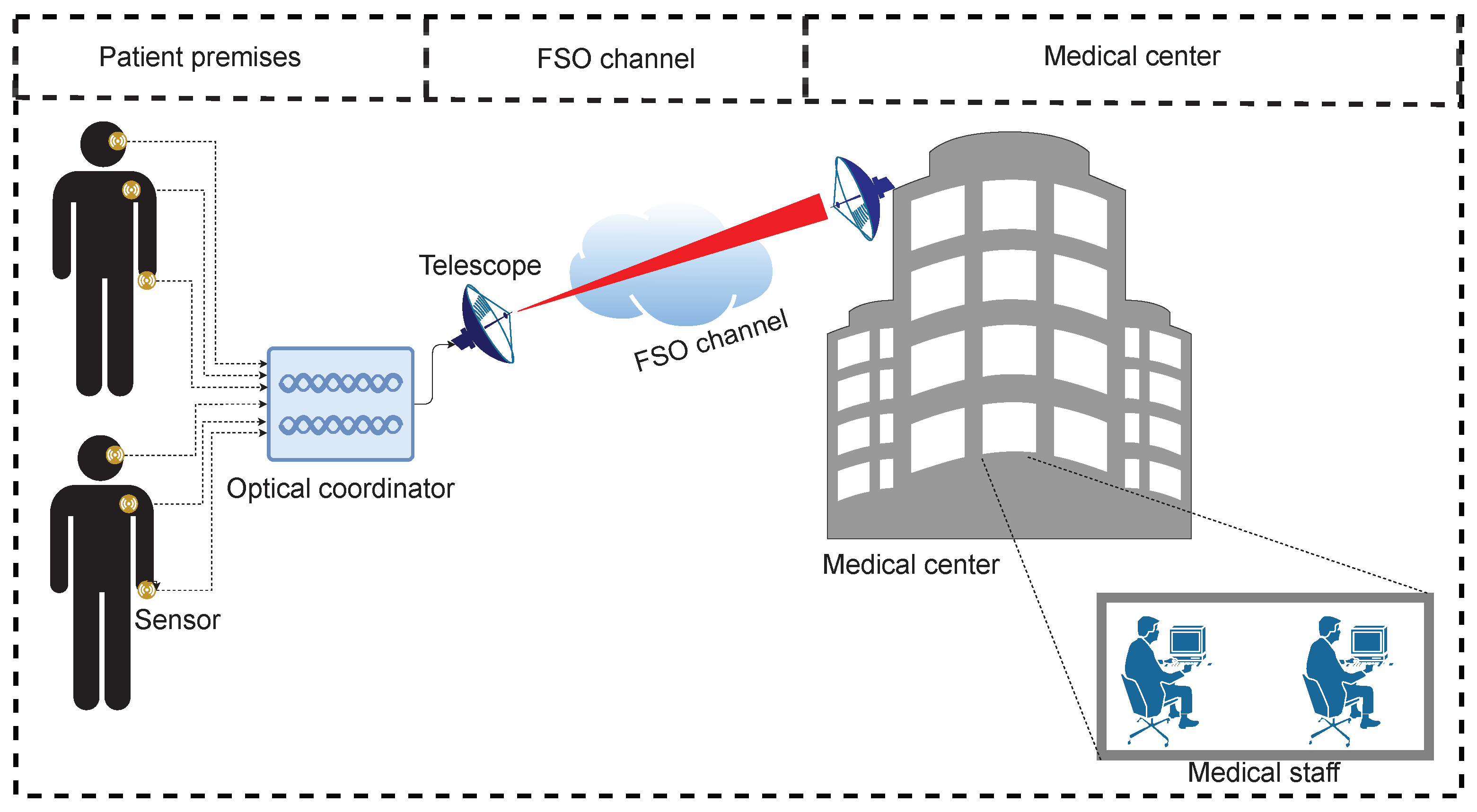
E-health solutions are best suited for remote health monitoring of elderly citizens and ailing or disabled persons living in old age homes, pandemic-hit areas, or who have any other hindrance in interacting with medical staff [2]. Moreover, e-health platforms can deliver optimum results in situations where increased physician and patient engagement, improvements in clinical quality, use of evidence based medication, and lower medical expenditures are required [8]. Recent commercial e-health platforms based on AI-enabled health devices, mobile health tracking, telemedicine, patient portals, and blockchain electronic health records include Vantage Health, Doctor-on-Demand, Practo, Inside Tracker, Precision Nutrition, etc. [40]. An illustration of the proposed OBAN based on FSO wireless technology is shown in Figure 1. FSO is an optical communication technology that uses light beams propagating in free space to wirelessly transmit data for telecommunication purposes [2]. It can provide increased capacity and cost efficiency while maintaining high data rates comparable to optical fiber-based links. FSO offers large license-free spectrum utilization, immunity to EMI, and high security [2]. FSO technology has the potential to resolve the main issues of large installation cost and time consumption typically associated with optical fiber-based systems [2]. However, FSO links can be affected by various disturbances, as discussed above [2].
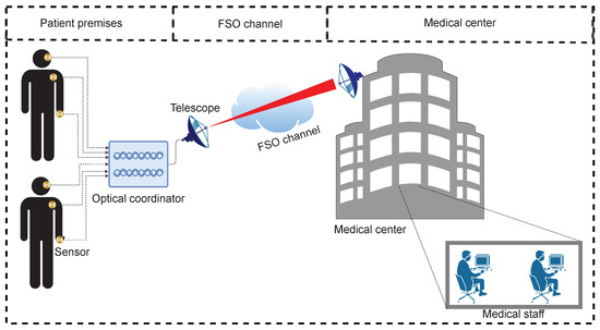
Figure 1.
Illustration of the proposed work.
In the proposed system, different on-body sensors for measuring critical physiological parameters such as body temperature, pulse rate, cough, blood pressure, electrocardiogram (ECG), electroencephalogram (EEG), oxygen saturation level, blood glucose level, etc., are mounted on the bodies of patients. All sensors are directly connected to an optical coordinator. The coordinator is located at a fixed position in the patient’s room. It encodes signals from the sensors using the proposed 2D-spectral/spatial DW-ZCC code, then the combined optical signal is transmitted over the FSO channel towards the medical center. On the receiving side, the optical signal is decoded, then data from each sensor are recovered via photodetection for analysis by medical staff, as shown in the Figure 1. It is clear that FSO technology can help to provide a low cost alternative for implementing the proposed OBAN, thereby resolving the issues associated with RF-based counterparts discussed in the previous section. Moreover, data privacy, multiple access, and cancellation of MAI are achieved using the proposed 2D-spectral/spatial OCDMA.
3. Proposed 2D DW-ZCC Code
The OCDMA codes based on SAC are simple and efficient 1D codes, and have been proposed as an excellent means of cancelling the MAI using balanced detection; in addition, they have high spectral efficiency and built-in security features [32]. However, these codes become inefficient when handling an increasing number of on-body sensors [32]. Therefore, multidimensional OCDMA codes were developed by combining different characteristics of the signal to resolve this drawback of 1D OCDMA codes [32]. The spectral/spatial combination is the most attractive approach for implementing 2D OCDMA codes.
The proposed 2D-spectral/spatial DW-ZCC code is formed by a combination of 1D DW-ZCC codes employed in the spectral/spatial domain. The DW family of codes is primarily composed of three variants: DW, modified double weight (MDW), and enhanced double weight (EDW). The name “double weight” comes from the fact that chips of the code sequence are placed adjacent to one another. This property of DW codes make them superior to their existing counterparts due to their ease of design and implementation, as it reduces the number of filters used in the encoder and decoder. Each DW code has unique characteristics related to its weight (w), auto- and cross-correlation properties , and code length . Among the family of DW codes, DW is the oldest code, first presented in [41]. DW code essentially consists of a matrix, where K is the number of sensors and N is the code length. The basic DW code matrix can be written as follows.
It can be observed that the conventional DW code has , , and . In order to develop a code with adjacent code placement and zero cross-correlation property, the conventional DW code matrix can be modified as follows.
The DW-ZCC code matrix has , , and . It can be observed that reduction in the cross-correlation property to an ideal zero increases the code length in comparison with its conventional counterpart, as well as that the code length is inversely proportional to the number of users. Furthermore, long code lengths are considered disadvantageous in implementations, as either very wideband sources or very narrow filter bandwidths are required [42]. Therefore, in order to ensure a large cardinality system, in this paper we propose a 2D-spectral/spatial DW-ZCC code that employs 1D DW-ZCC code along the spectral domain and spatial domain (the Xth and Yth axes, respectively). The length of both code sequences is dependent on the weight and the total number of code words.
The proposed code is denoted by , where M×N represents size of the 2D-spectral/spatial DW-ZCC code, w is weight of the code, and and respectively represent the auto- and cross-correlation properties of the proposed code. Let represent the 1D DW-ZCC code sequences employed in the spatial domain and let be 1D DW-ZCC code sequences utilized in the spectral domain. An example for two different 1D enhanced multi-diagonal (EMD) sets X and Y with and is shown in Table 1.

Table 1.
Spectral (X) and spatial (Y) code sequences extracted from 1D DW-ZCC code.
Now, both the Xth and Yth code sequences are used to build the proposed 2D-spectral/ spatial DW-ZCC code matrix as described below.
Table 2 shows the 2D-spectral/spatial DW-ZCC code matrix for S sensors obtained by combining the spectral code sequence X and spatial code sequence Y as , where X and Y are the gth and hth code sequences of X and Y, respectively, with and . Here, K and K respectively represent the number of codes corresponding to the number of sensors in both the spectral and spatial code sequences.
Table 2.
Proposed 2D-spectral/spatial DW-ZCC code.
Code Properties
To determine the auto- and cross-correlation properties of the proposed codes, four different characteristic matrices are defined as DZ, where . The four codes can be represented mathematically as follows:
where and represent the complementary code sequences for X and Y, respectively. Moreover, the 2D-spectral/spatial DW-ZCC code DZ is provided by a set of elements dz, where and . Hence, for the proposed 2D-spectral/spatial DW-ZCC code using DZ and DZ can be expressed as
where dz is the (i,j)th entry of DZ and dz(g,h) is the (i,j)th entry of DZ. Table 3 provides the auto- and cross-correlation properties for the 2D-spectral/spatial DW-ZCC code generated from Equation (2).
Table 3.
Correlation properties for 2D-EMD code with and .
Thus, the cross-correlation of DZ and DZ can be denoted as follows.
The obtained auto- and cross-correlation properties can be utilized to determine the receiver architectures and type of detection technique employed to recover the intended signal. It can be observed that each sequence exhibits the maximum power units with itself and minimum or zero power units with adjacent and other codes. Therefore, a direct detection scheme can be employed at the receiving end to recover the intended signal.
OCDMA codes exhibit high levels of security, as each sensor receives a unique code that can only be decoded through specific equipment at the respective receiver [43]. This inherent security feature is enhanced threefold in the proposed architecture by introducing second and third dimensions in the form of spatial and temporal encoding. Therefore, extension of the 1D DW-ZCC code to higher dimensions not only enhances performance, it elevates overall security of that particular network and makes it very difficult for an eavesdropper to recover the transmitted signal. Furthermore, code complexity is found to effect security of the OCDMA codes, as increased code complexity can increase the total amount of power required to transmit the encoded signal. This increases the overall signal-to-noise ratio (SNR) that is required for an eavesdropper to “break” the encoding by only a few dB [44]. However, the proposed 2D-spectral/spatial DW-ZCC code is developed with a technique that yields limited weight and length in comparison with the existing counterpart. Consequently, the proposed code can offer a relatively high level of security by employing adjacent code sequences and a multi-dimensional code structure with efficient performance parameters.
The proposed approach employs FSO channels to transmit the signal between the sensors and the medical center. One of the problems associated with FSO is its short range and dependance on weather conditions. However, these can be overcome by the proposed unique code sequence with multiple dimensions, which can mitigate MAI between adjacent subscribers and support high-capacity communication over large distances. Nevertheless, it is pertinent to mention that the overall capacity and cardinality of the system is dependent on weather conditions, and although the proposed model is able to provide desirable performance in adverse environments, channel conditions might affect performance in certain conditions.
4. System and Channel Model
A point-to-point line-of-sight FSO link between the optical coordinator and medical center based on an intensity modulation–direct detection (IM-DD) scheme is considered in this work. The optical signal travels in a straight line through the FSO channel. The turbulent channel is considered as memoryless, stationary, and ergodic; therefore, the system can be modeled by the following equation:
where g is the intensity gain, y is the received signal, x is the modulated optical signal, is the photodetector (PD) conversion efficiency, I is the intensity, and n is additive white Gaussian noise (AWGN). We consider that the received signal’s intensity is affected by atmospheric attenuation, turbulence, and geometrical losses. The atmospheric attenuation is modeled by the Beer–Lambert principle, provided by the following equation [45]:
where is the scattering coefficient. The scattering coefficient is weather-dependent and is a function of the visibility , which can be calculated by [45].
The received signal’s intensity at the PD randomly fluctuates, which is known as intensity scintillation or simply turbulence [46]. This is a major source of performance degradation in FSO systems. Different channel models were introduced to estimate the turbulence, including the gamma–gamma, log-normal, and negative exponential channel models [46]. The log-normal channel model is typically used for weak turbulence when FSO channel range is on the order of a few kilometers. The probability density function (PDF) of received signal’s intensity follows a log-normal distribution, and is provided as follows [45,46]:
where is the intensity variance due to turbulence, provided by [46]
where L is range of FSO channel, is the wave number, and C is the refractive index structure parameter. The value of the C parameter is time-dependant and varies in the range of 10 to 10 m, respectively indicating weak to strong turbulence [46].
5. Proposed Architecture
The 2D-spectral/spatial DW-ZCC code for eight on-body sensors used for the implementation of the proposed setup is provided in Table 4; it uses the following four codes in the spectral domain: X1, X2, X3, and X4, and the following two codes in the spatial domain: Y1 and Y2.
Table 4.
The 2D-spectral/spatial DW-ZCC code used to implement the proposed setup.
The block diagram of the proposed setup is shown in Figure 2. We consider that the sensors are attached to the bodies of patients and generate electrical data signals that are fed to the optical coordinator, which is used to perform the necessary encoding in the optical domain, as mentioned in Section 2. The optical coordinator is the main part of the architecture and is where all encoding related tasks take place using a combination of continuous wave (CW) lasers, power splitters, and couplers [2]. The optical coordinator houses 8 × CW lasers and 8 × power splitters. The CW lasers, each having 10 dBm power, are centered at nm, nm, nm, nm, nm, nm, nm, and nm. Each CW laser is first split into two parts using 50:50 power splitters, then two different parts are combined using optical couplers as per the spectral encoding scheme presented in Table 4. The electrical data generated from each on-body sensor are encoded using the non-return to zero On–Off keying (NRZ-OOK) format and modulate an optical carrier obtained by coupling two different optical signals as per spectral encoding scheme. For instance, parts of and are combined to translate the sensor’s data into spectral representation with reference to code sequence of 11,000,000 as shown in Table 4. The data modulation process is shown in inset of Figure 3.
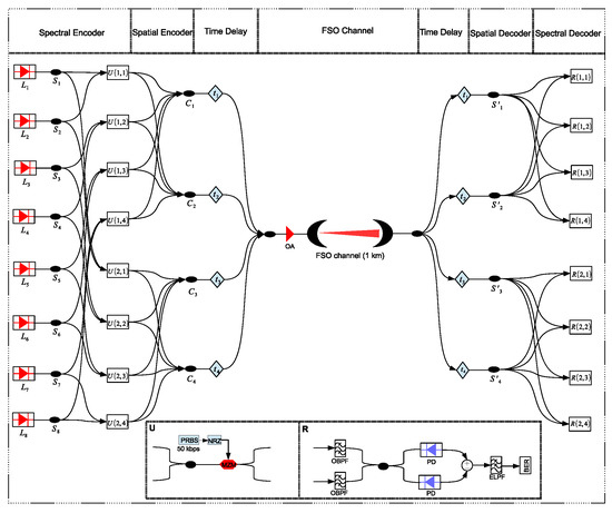
Figure 2.
Block diagram of the proposed setup and code implementation, L: CW lasers, S: Power splitters, U: Sensors, C: Star couplers, OA: Optical amplifier, S: Power splitters, R: Receivers, PRBS: Pseudo-random bit sequence generator, NRZ: Non-return to zero pulse generator, MZM: Mach–Zehnder modulator, OBPF: Optical bandpass filter, PD: Photodetector, ELPF: Electrical lowpass filter, BER: Bit error rate estimator.
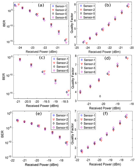
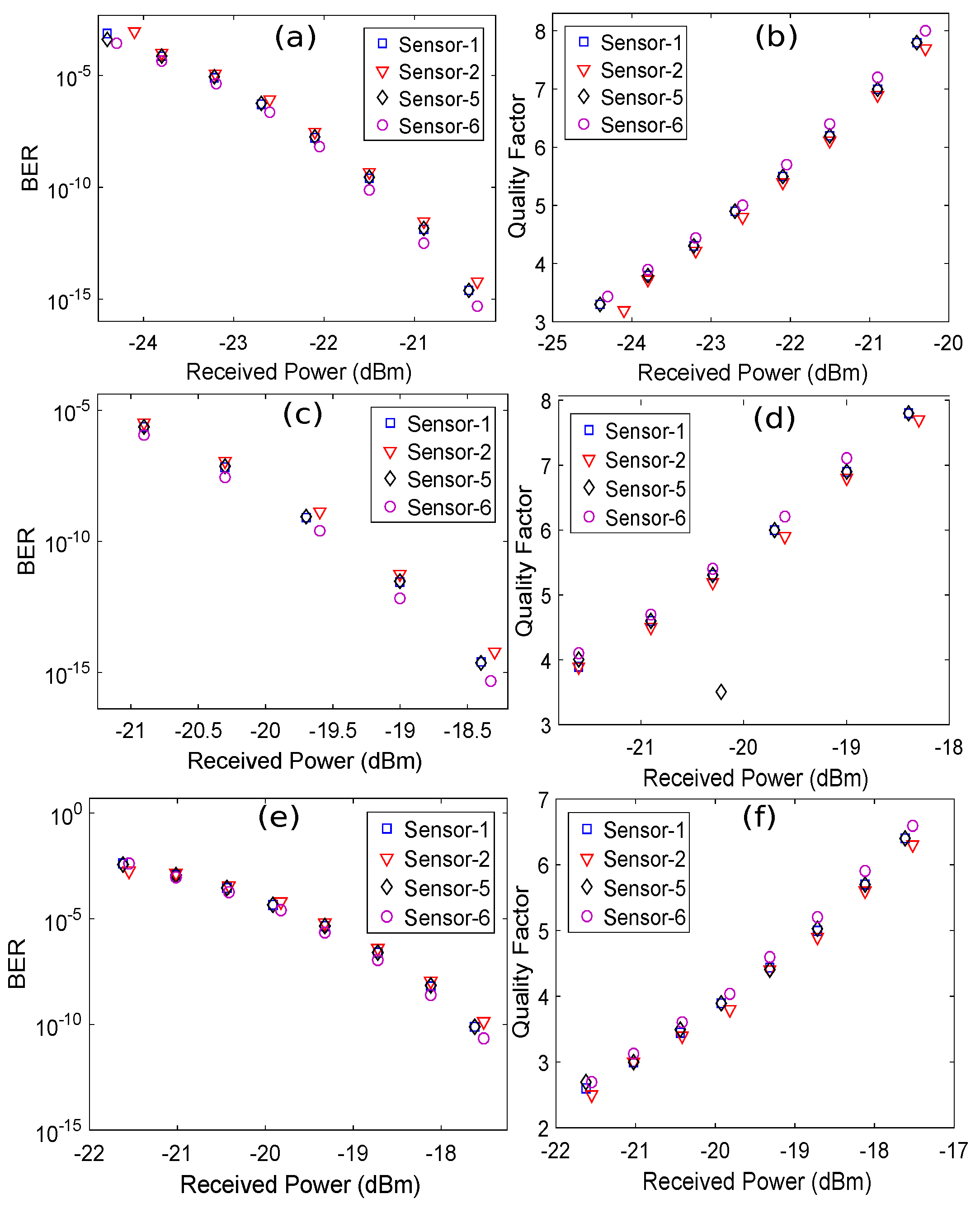
Figure 3.
BER versus (a,c,e) Received power plots for atmospheric attenuation of 2 dB/km, 11 dB/km, and 21 dB/km, respectively and (b,d,f) Q-factor plots for atmospheric attenuation of 2 dB/km, 11 dB/km, and 21 dB/km, respectively. A value of the C parameter equal to 5 × 10 m was used.
After performing spectral encoding, the spectrally encoded signals at the outputs of the Mach–Zehnder modulators (MZMs) are split into two equal parts to implement the spatial encoding. This is achieved by coupling the parts of spectrally encoded optical signals at their respective star couplers as per the spatial encoding scheme presented in Table 4. For instance, the parts of the optical signals at the output of sensor U(1,1) are connected to their respective star couplers, i.e., C and C, with reference to the code sequence of 1100, as shown in Table 4. Similarly, spatial encoding is performed for all sensors following the respective code sequence. A time delay is introduced in the spectral/spatial encoded optical signals at the output of the star couplers to eliminate multiple parallel FSO channels between the transmitter and medical center, as shown in Figure 2. The time delay is calculated for each spectral/spatial encoded signal using the following equation [47]:
where D represents the chip placement in the coding design, is the bit’s time duration, and S expresses the number of time slots. The time-delayed spectral/spatial encoded optical signals are then combined and amplified to a suitable power level using an optical amplifier (OA), ensuring a sufficient power budget. The amplified signal is then transmitted from the optical coordinator to the medical center over a 1 km FSO channel using a transmitter telescope, as shown in Figure 2. The FSO channel used in this work is modeled using the log-normal distribution [46], and the details have been discussed in Section 4. The optical signal transmitted over the FSO channel is received using a receiver telescope. The received signal is split into four equal parts, and a time delay is introduced in each spectral/spatial encoded signal according to following equation [47].
To perform spatial decoding, each signal after the time delay is again split into four equal parts; the required decoding for U(1,1) is performed as per the respective code sequence. Similarly, spectral decoding is performed at the respective receivers by employing two optical bandpass filters (OBPFs) tuned at the intended wavelengths in accordance with the respective code sequence and balanced photodetection. After balanced photodetection, the electrical signal is lowpass filtered and sent to the BER estimator for BER measurement. A summary of the major simulation parameters for this setup is shown in Table 5.
Table 5.
Important simulation parameters.
6. Results and Discussions
The BER performance of the received signals is analyzed at the medical center using BER plots for different weather conditions such as light haze, heavy haze, and heavy fog while considering the log-normal channel model. These conditions were simulated in this work by varying the value of the atmospheric attenuation coefficient (). Therefore, the values of for light haze, heavy haze, and heavy fog used in the simulation were 2 dB/km, 11 dB/km, and 21 dB/km, respectively [48]. Similarly, the weak turbulence regime was characterized by a C value of 5 × 10 m. The BER values were calculated using the statistical method in OptiSystem by observing the eye diagram of the received signal at the output of the lowpass filter (LPF), as shown in the inset of Figure 2. The optical power of the incident signal at the PD was varied using a variable optical attenuator (VOA) to determine its effect on the BER value of the received signal. The optical power was measured using a power meter before the PD. Figure 3 shows the BER and Q-factor versus the received optical power plots for different weather conditions.
For simplicity, only four on-body sensors are randomly selected here to discuss their performance. The minimum value of optical power received at the PD that is required to achieve a BER of 10 is called the receiver sensitivity. It can be seen from Figure 3a that the receiver sensitivity value of sensors 1, 2, 5, and 6 is around −21.5 dBm for = 2 dB/km. The receiver sensitivity value of sensors 1, 2, 5, and 6 becomes −19.6 dBm for = 11 dB/km, as shown in Figure 3c. A power penalty of around 1.9 dBm is observed on increasing the value of from 2 dB/km to 11 dB/km. Similarly, Figure 3e shows that the receiver sensitivity of sensors 1, 2, 5, and 6 is around −17.5 dBm. A penalty of 2.1 dBm is noticed on further increasing the value of from 11 dB/km to 21 dB/km. It is evident that the receiver sensitivity values of the sensors degrade when increasing the value of . The Q-factor plots in Figure 3b,d,f show that the Q-factor values of the sensors typically increase when increasing the received optical power. However, the Q-factor value decreases on increasing the value of , corresponding to a fixed value of the received optical power. To further detail the performance of the sensors, we obtained the eye diagrams of sensor 1 and sensor 5 at the output of the LPFs for different values of ; the value of C that we used was 5 × 10 m.
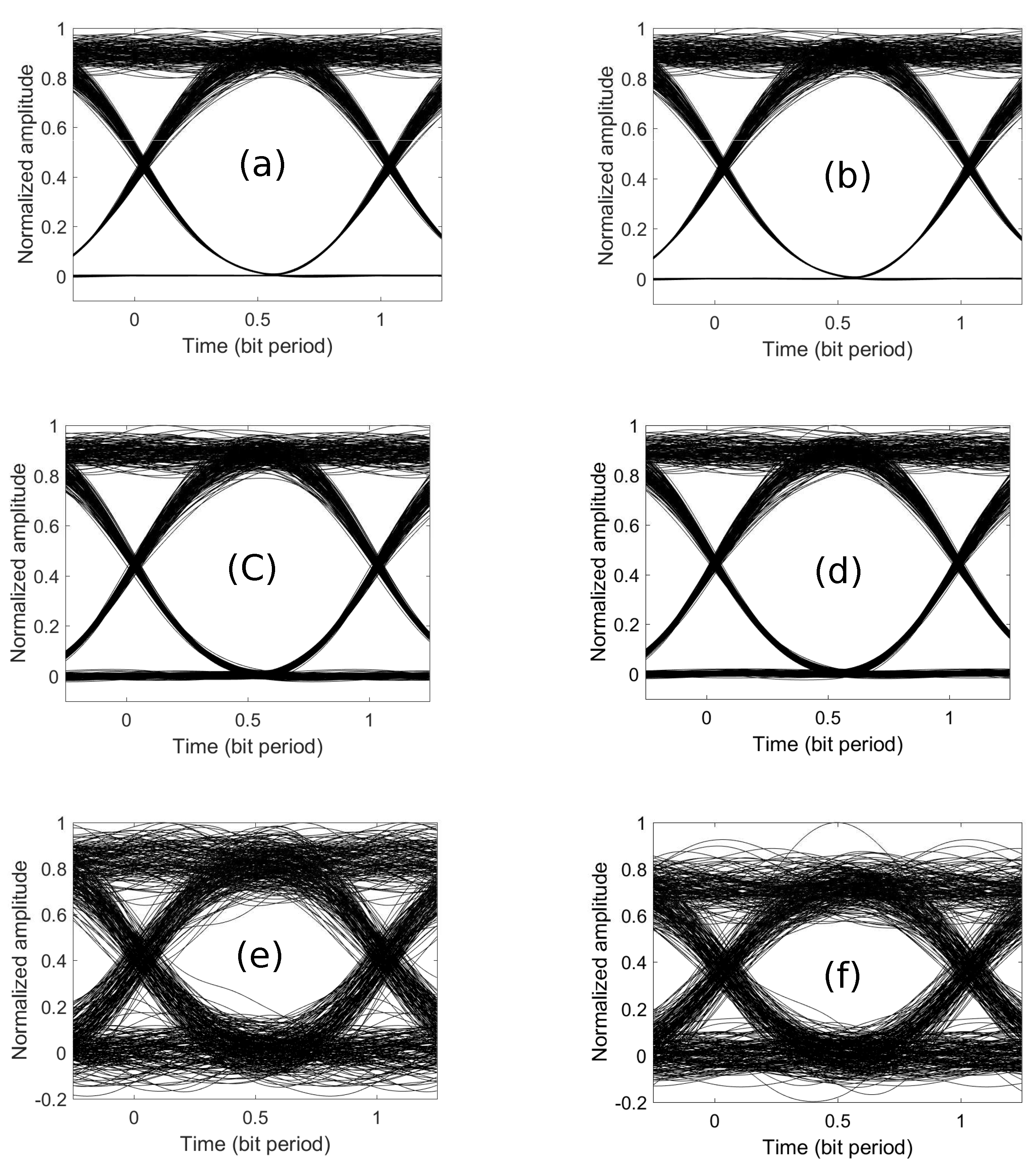
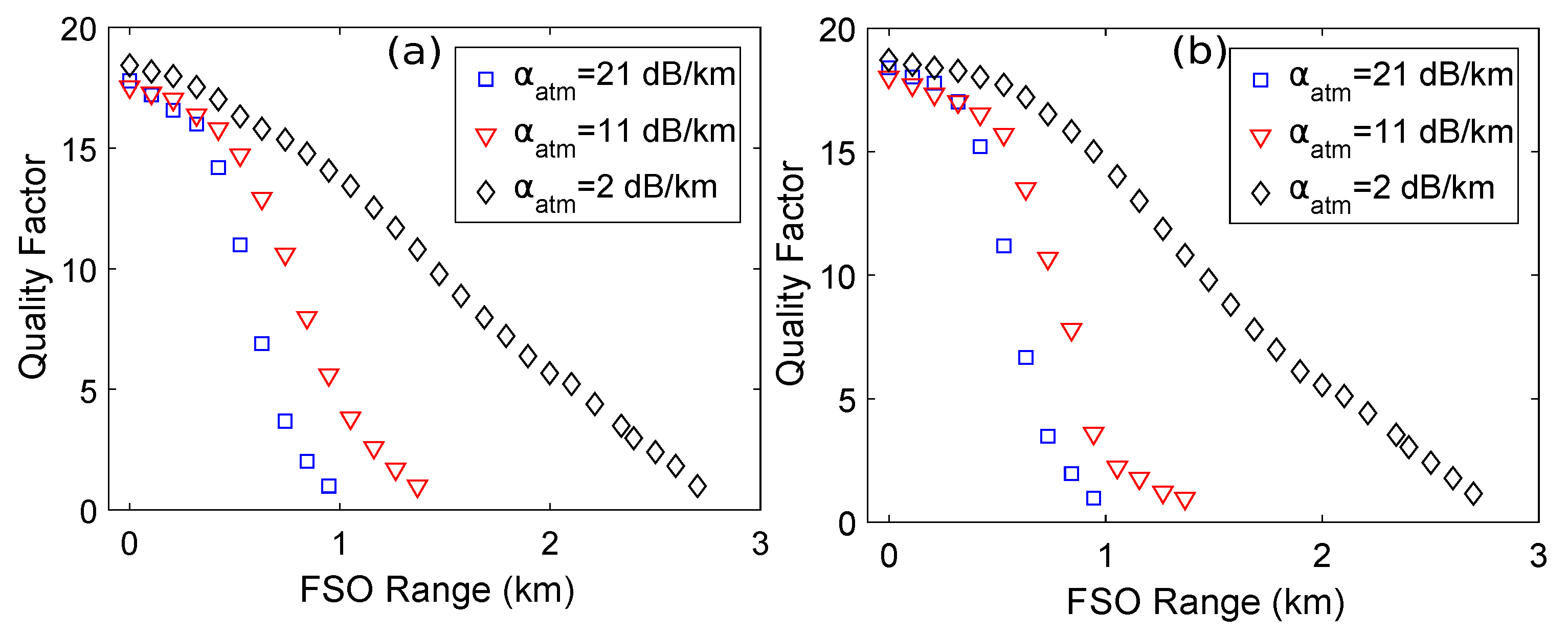
It is evident from Figure 4 that intensity variations over the received signals increased upon increasing the value of atmospheric attenuation, which results in the eye diagrams of the received signals deteriorating and closing further. However, the eye diagrams of the sensors have wide openings that result in easier discrimination between the zeros and ones at the receiver. To observe the performance of the sensors for different ranges of the FSO channel while considering different weather conditions, the length of the FSO channel was gradually increased in order to observe its effect on the Q-factor. Figure 5 shows the plots for the FSO range versus the Q-factor for sensor 1 and sensor 5 with different values of atmospheric attenuation.
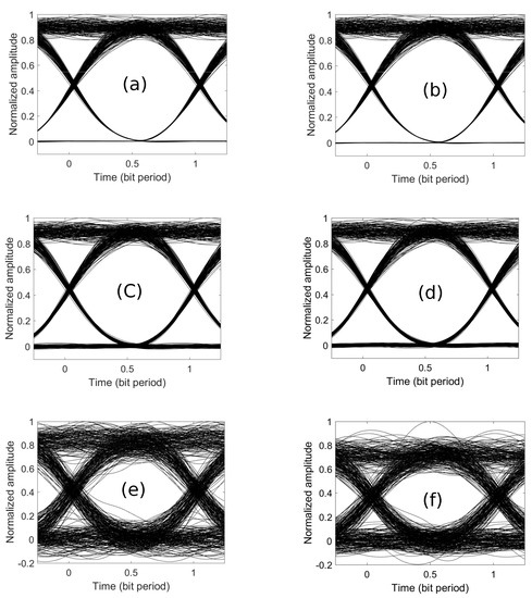
Figure 4.
Normalized eye diagrams of sensors for different values of atmospheric attenuation. (a,b) Sensor-1 and sensor 5 at = 2 dB/km. (c,d) Sensor 1 and sensor 5 at = 11 dB/km. (e,f) Sensor 1 and sensor 5 at = 21 dB/km.
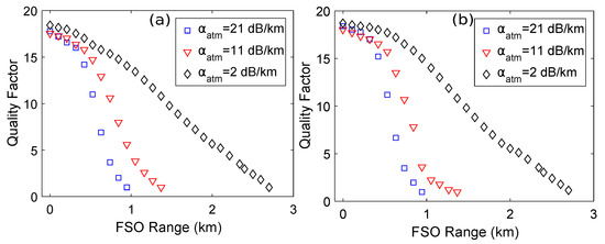
Figure 5.
Q-factor versus FSO range plots for different values of atmospheric attenuation: (a) sensor 1 and (b) sensor 5. A value of the C parameter equal to 5 × 10 m was used.
It is clear that a maximum range of around 2.75 km is achieved for sensor 1 and sensor 5 at = 2 dB/km, while the minimum range of around 1 km is achieved for sensor 1 and sensor 5 at = 21 dB/km, corresponding to a Q-factor of 1. Moreover, it can be observed that the value of the Q-factor decreases on increasing the FSO range for all values of atmospheric attenuation.
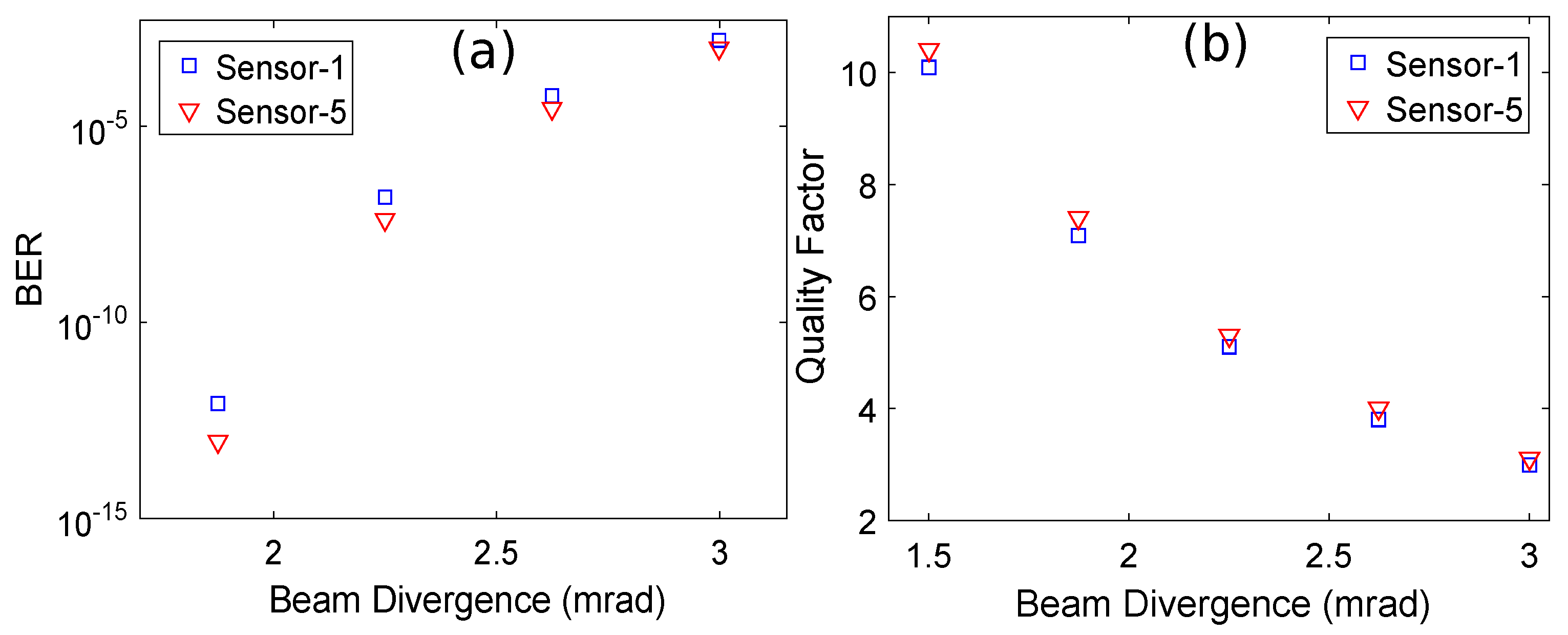
To show the effect of variation in the receiver telescope’s aperture diameter and beam divergence over the BER and Q-factor, the aperture diameter and beam divergence were gradually increased in order to observe their effects on the BER and Q-factor. Figure 6 shows plots of the BER and Q-factor versus the receiver aperture diameter for sensor 1 and sensor 5 obtained at = 21 dB/km; the values of C and the beam divergence are 5 × 10 m and 2 mrad, respectively.
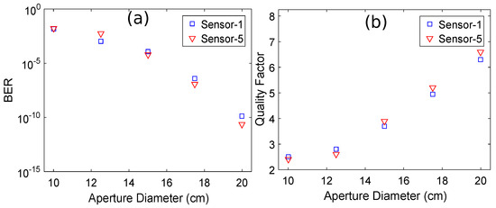
Figure 6.
(a) Plot of BER versus the receiver aperture diameter and (b) plot of the Q-factor versus the receiver aperture diameter.
It is clearly evident that the BER decreases while the Q-factor increases on increasing the receiver aperture diameter. Similarly, Figure 7 shows plots of the BER and Q-factor versus the beam divergence for sensor 1 and sensor 5 obtained at = 21 dB/km; the values of C and the receiver aperture diameter were 5 × 10 m and 20 cm, respectively.
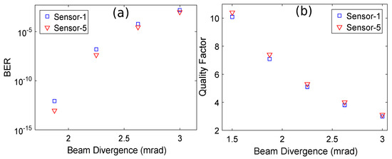
Figure 7.
(a) BER versus beam divergence plot and (b) Q-factor versus beam divergence plot.
It is clearly evident that the BER increases and the Q-factor decreases when increasing the beam divergence.
7. Cost Analysis
In this section, we analyze the CAPEX of the proposed architecture in comparison with the conventional 2D-spectral/spatial FSO system to determine the overall impact of introducing the time-delay units on the cost of implementation [49,50,51,52]. For a fair analysis of the CAPEX, the following system parameters and components were considered for the proposed and conventional 2D-spectral/spatial FSO system:
- Analysis was performed for sixteen nodes with and , where and respectively represent the number of spectral and spatial codes.
- Spectral/spatial encoders and decoders were the same for both architectures, as major modifications were made in the star coupler section through introduction of time-delay units for the proposed architecture. Therefore, analysis was carried out for the components between the power couplers and combiners.
- The per-unit cost of the FSO transceiver module was considered in the analysis through a market survey.
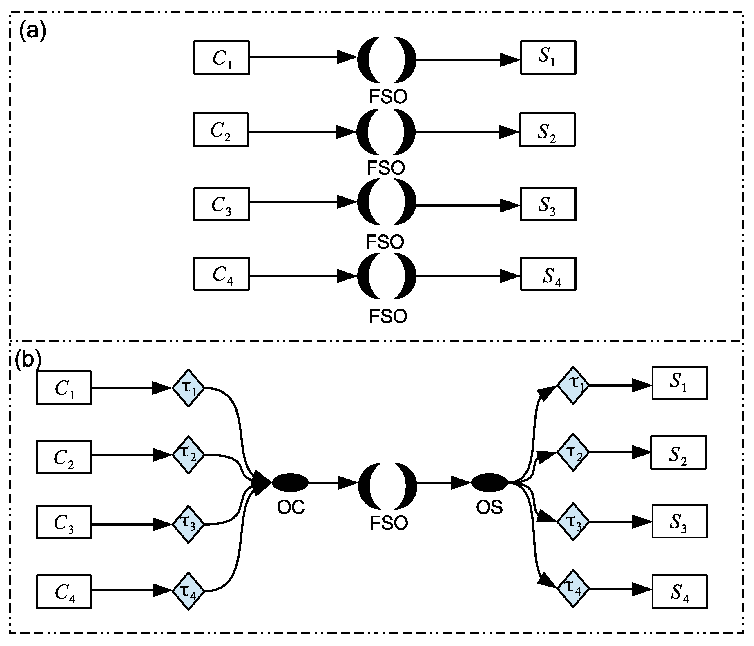
Figure 8a shows the block diagram of the conventional 2D-spectral/spatial FSO system, where each combiner and splitter pair represent a star coupler and relate to dedicated FSO links to avoid interference between repeated codes. Figure 8b shows the block diagram of the proposed architecture that employs time-delay units along with an optical combiner and optical splitter to replace multiple parallel FSO links with a single FSO path.
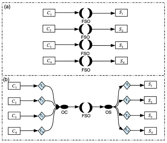
Figure 8.
Block diagrams of (a) the conventional 2D-spectral/spatial FSO system and (b) the proposed architecture with time-delay units.
Now, the total CAPEX required for development of both networks can be written as follows:
where CAPEX represents the capital expenditure for the conventional 2D-spectral/spatial FSO system with number of optical couplers (OC), FSO links, and optical splitters (OS). Similarly, CAPEX shows the total cost of implementation for the proposed model with number of OCs, time-delay units, and OSs, along with installation of a single OC, FSO link, and OS to facilitate the implementation of time-delay units to compensate for the use of multiple parallel FSO links.
Table 6 represents the cost of each component shown in Figure 8 [49,50]. The cost of each component for the proposed and conventional architectures are used in Equations (11) and (12) to determine the cost of implementation for each component in both architectures along with the total CAPEX for the entire architecture.
Table 6.
Cost of each component shown in Figure 8.
Table 7 shows the CAPEX required for installation of each component in both architectures. The same analysis was performed for networks with a total of sixteen nodes and with and . It can be observed that a major difference exists between the cost of implementing FSO links in the two architectures. This can be attributed to the proposed architecture having a reduced number of parallel FSO links, specifically, a single link, and the introduction of time-delay units with a relatively lower in cost in comparison to the additional FSO links. Similarly, the addition of extra components in the proposed architecture for implementation of time-delay units has only a minuscule effect on the cost of each component, as all of these components are relatively low in cost.
Table 7.
CAPEX required for installation of each component in the two architectures.
Table 8 shows a comparison of the total CAPEX for the proposed and conventional 2D-spectral/spatial FSO systems.
Table 8.
Comparison of the total CAPEX for the proposed and conventional architectures.
The data show that the proposed architecture significantly reduces the cost of implementation in comparison with the conventional architecture. It is evident that utilization of low-cost time-delay units facilitates the implementation of a single FSO link to carry all traffic between the transmitter and receiver modules, unlike that conventional architecture, which requires FSO links to avoid interference between repeated codes. Consequently, the proposed architecture is more efficient in terms of CAPEX compared to the conventional architecture.
We compared the important results and techniques of this work with the results and techniques of similar past studies. Table 9 shows a thorough comparison between the proposed work and past works. It is evident from Table 9 that the proposed architecture is superior compared to past architectures in terms of flexibility, performance, security, compatibility with GR trends, and the recent recommendations of the IEEE 802.15.6 Task Group on future BANs.
Table 9.
Comparison between the proposed work and similar past studies.
8. Conclusions
In this paper, a flexible and secure optical body area network based on free space optics wireless technology and a time-delayed two dimensional spectral/spatial optical code-division multiple access system is demonstrated using numerical simulations. The proposed setup consists of eight sensors mounted on the body of a patients that record their vital physiological data. The data of each sensor are secured using two dimensional double-weighted zero-cross correlation codes. After spectral/spatial encoding, the data of each signal are time-delayed and the combined optical signal is transmitted over an FSO channel with a range of 1 km towards the medical center. The data of each sensor are decoded and recovered after photodetection at the medical center for further analysis by the medical staff. The performance of the sensors ws analyzed using bit error rate and Q-factor plots for different weather conditions while considering a log-normal channel. The effect of variations in the receiver aperture diameter and beam divergence over the bit error rate and quality factor of the received signals was evaluated as well. Secure and error-free transmission of sensor data between the transmitter and remote medical center was successfully achieved under different weather conditions. The CAPEX of the proposed architecture was analyzed and compared with a conventional 2D-spectral/spatial FSO system to determine the overall impact of introducing time-delay units on the cost of implementation. The proposed architecture is flexible, cost-efficient, secure, and compatible with the green radio trend, while fulfilling the recent recommendations of the IEEE 802.15.6 Task Group on future body area networks.
Author Contributions
J.M., W.A.I. and K.K.Q. introduced the concept and model; F.K., J.M. and A.U.H. performed the simulations; F.K. wrote the paper; J.M. and A.U.H. proofread the paper; F.K. and W.A.I. prepared the plots and figures and validated the results; and J.M. supervised the project. All authors have read and agreed to the published version of the manuscript.
Funding
This research received no external funding.
Institutional Review Board Statement
Not applicable.
Informed Consent Statement
Not applicable.
Data Availability Statement
The data and material generated during this study are available from the corresponding author on request.
Acknowledgments
K. K. Qureshi would like to acknowledge the support provided by KFUPM through project no. INCS 2303.
Conflicts of Interest
The authors declare no conflict of interest.
Abbreviations
The following abbreviations are used in this manuscript:
| FSO | Free Space Optics |
| OBAN | Optical Body Area Network |
| BAN | Body Area Network |
| BIBD | Balanced Incomplete Block Design |
| EMI | Electromagnetic Interference |
| RF | Radio Frequency |
| OCDMA | Optical Code Division Multiple Access |
| BER | Bit Error Rate |
| CAPEX | Capital Expenditure |
| GR | Green Radio |
| PPM | Pulse Position Modulation |
| MAI | Multiple Access Interference |
| PIIN | Phase-Induced Intensity Noise |
| ZCC | Zero Cross-Correlation |
| ECG | Electrocardiogram |
| EEG | Electroencephalogram |
| SAC | Spectral Amplitude Coding |
| EMD | Enhanced Multi-Diagonal |
| IMDD | Intensity Modulation–Direct Detection |
| PD | Photodetector |
| PV | Permutation Vector |
| Probability Density Function | |
| DW | Double Weight |
| DEU | Diagonal Eigenvalue Unity |
| MDW | Modified Double Weight |
| EDW | Enhanced Double Weight |
| CW | Continuous Wave |
| NRZ-OOK | Non-Return to Zero On–Off Keying |
| MZM | Mach–Zehnder Modulator |
| AWGN | Additive White Gaussian Noise |
| OA | Optical Amplifier |
| OBPF | Optical Bandpass Filter |
| OC | Optical Coupler |
| OS | Optical Splitter |
| OFDMA | Orthogonal Frequency Division Multiple Access |
References
- Mehmood, G.; Khan, M.Z.; Abbas, S.; Faisal, M.; Rahman, H.U. An energy-efficient and cooperative fault-tolerant communication approach for wireless body area network. IEEE Access 2020, 8, 69134–69147. [Google Scholar] [CrossRef]
- Mirza, J.; Ghafoor, S.; Ahmad, W.; Salman, A.; Qureshi, K.K. Integrating ultra-wideband and free space optical communication for realizing a secure and high-throughput body area network architecture based on optical code division multiple access. Opt. Rev. 2021, 28, 525–537. [Google Scholar] [CrossRef]
- Latre, B.; Braem, B.; Moerman, I.; Blondia, C.; Demeester, P. A survey on wireless body area networks. Wirel. Netw. 2011, 17, 1–18. [Google Scholar] [CrossRef]
- Dhatchayeny, D.R.; Chung, Y.H. Optical extra-body communication using smartphone cameras for human vital sign transmission. Appl. Opt. 2019, 58, 3995–3999. [Google Scholar] [CrossRef]
- U.S. NHE Fact Sheet. Available online: https://www.cms.gov/research-statistics-data-and-systems/statistics-trends-and-reports/nationalhealthexpenddata/nhe-fact-sheet (accessed on 5 August 2023).
- Haddad, O.; Khalighi, M.-A.; Zvanovec, S. Performance analysis of optical extra-WBAN links based on realistic user mobility modeling. Opt. Eng. 2022, 61, 026113. [Google Scholar] [CrossRef]
- Chavez-Santiago, R.; Sayrafian-Pour, K.; Khaleghi, A.; Takizawa, K.; Wang, J.; Balasingham, I.; Li, H.-B. Propa gation models for IEEE 802.15. 6 standardization of implant communication in body area networks. IEEE Commun. Mag. 2013, 51, 80–87. [Google Scholar] [CrossRef]
- Kanwal, B.; Kanwal, F.; Kausar, T.; Habib, N.; Atieh, A.; Mirza, J. Optical Chaos Based Secure Optical Body Area Network Employing Polarization Multiplexing and Free Space Optics for e-Health Applications. In Proceedings of the IEEE International Bhurban Conference on Applied Sciences and Technology (IBCAST), Islamabad, Pakistan, 16–20 August 2022; pp. 1055–1060. [Google Scholar]
- Chevalier, L.; Sahuguede, S.; Julien-Vergonjanne, A. Wireless optical technology based body area network for health monitoring application. In Proceedings of the IEEE International Conference on Communications (ICC), London, UK, 8–12 June 2015; pp. 2863–2868. [Google Scholar]
- Dhatchayeny, D.R.; Cahyadi, W.A.; Teli, S.R.; Chung, Y.-H. A novel optical body area network for transmission of multiple patient vital signs. In Proceedings of the IEEE International Conference on Ubiquitous and Future Networks (ICUFN), Milan, Italy, 4–7 July 2017; pp. 542–544. [Google Scholar]
- Dhatchayeny, D.R.; Arya, S.; Chung, Y.H. Patient mobility support for indoor non-directed optical body area networks. Sensors 2019, 19, 2297–2310. [Google Scholar] [CrossRef]
- Haddad, O.; Khalighi, M.A.; Zubow, A. Wireless body-area networks in medical applications using optical signal transmission. In Proceedings of the in IEEE Optical Fiber Communications Conference and Exhibition (OFC), Virtual, 6–11 June 2021; pp. 1–3. [Google Scholar]
- Haddad, O.; Khalighi, M.A.; Zvanovec, S.; Adel, M. Channel characterization and modeling for optical wireless body-area networks. IEEE Open J. Commun. Soc. 2020, 1, 760–776. [Google Scholar] [CrossRef]
- Chevalier, L.; Sahuguede, S.; Julien-Vergonjanne, A.; Combeau, P.; Aveneau, L. Investigation of wireless optical technology for communication between on-body nodes. In Proceedings of the IEEE International Workshop on Optical Wireless Communications (IWOW), Newcastle upon Tyne, UK, 21 October 2013; pp. 79–83. [Google Scholar]
- Chevalier, L.; Sahuguede, S.; Julien-Vergonjanne, A. Optical wireless links as an alternative to radio-frequency for medical body area networks. IEEE J. Sel. Areas Commun. 2015, 33, 2002–2010. [Google Scholar] [CrossRef]
- Hasan, H.J.; Khalighi, M.A.; García-Marquez, J.; Bechadergue, B. Performance analysis of optical-CDMA for uplink transmission in medical extra-WBANs. IEEE Access 2020, 8, 171672–171685. [Google Scholar] [CrossRef]
- Hasan, H.J.; Khalighi, M.A.; Jungnickel, V.; Alves, L.N.; Bechadergue, B. An energy-efficient optical wireless OFDMA scheme for medical body-area networks. IEEE Trans. Green Commun. Netw. 2022, 6, 1806–1818. [Google Scholar] [CrossRef]
- Mirza, J.; Imtiaz, W.A.; Aljohani, A.J.; Ghafoor, S. A high bit rate free space optics based ring topology having carrier-less nodes. IET Commun. 2021, 15, 1530–1538. [Google Scholar] [CrossRef]
- Ghafoor, S.; Aljohani, A.J.; Mirza, J.; Khan, A.; Bashir, S. A novel technique for secure transmission of two channels using a single optical pulse position modulated signal for free space optical communication. Opt. Quantum Electron. 2023, 55, 350. [Google Scholar] [CrossRef]
- Ruiz, R.B.; Zambrana, A.G.; Vazquez, B.C.; Qaraqe, K. Secure communication for FSO links in the presence of eavesdropper with generic location and orientation. Opt. Express 2019, 27, 34211–34229. [Google Scholar] [CrossRef]
- Eghbal, M.; Abouei, J. Security enhancement in free-space optics using acousto-optic deflectors. J. Opt. Commun. Netw. 2014, 6, 684–694. [Google Scholar] [CrossRef]
- Chatterjee, M.R.; Mohamed, A.; Almehmadi, F.S. Secure free-space communication, turbulence mitigation, and other applications using acousto-optic chaos. Appl. Opt. 2018, 57, 1–13. [Google Scholar] [CrossRef]
- Yang, Y.; Chen, C.; Zhang, W.; Deng, X.; Du, P.; Yang, H.; Zhong, W.-D.; Chen, L. Secure and private NOMA VLC using OFDM with two-level chaotic encryption. Opt. Express 2018, 26, 34031–34042. [Google Scholar] [CrossRef]
- El-Meadawy, S.A.; Shalaby, H.M.H.; Ismail, N.A.; Abd El-Samie, F.E.; Farghal, A.E.A. Free-space 16-ary orbital angular momentum coded optical communication system based on chaotic interleaving and convolutional neural networks. Appl. Opt. 2020, 59, 6966–6976. [Google Scholar] [CrossRef]
- Mohamed, A.; Chatterjee, M.R. Image intensity recovery with mitigation in the presence of gamma–gamma atmospheric turbulence using encrypted chaos. Opt. Eng. 2019, 58, 036110. [Google Scholar] [CrossRef]
- Alshaer, N.; Moawad, A.; Ismail, T. Reliability and security analysis of an entanglement-based QKD protocol in a dynamic ground-to-UAV FSO communications system. IEEE Access 2021, 9, 168052–168067. [Google Scholar] [CrossRef]
- Vu, M.Q.; Le, H.D.; Pham, A.T. Entanglement-based satellite FSO/QKD system using dual-threshold/direct detection. In Proceedings of the International Conference on Communications (ICC), Seoul, Republic of Korea, 16–20 May 2022; pp. 3245–3250. [Google Scholar]
- Singh, M.; Aly, M.H.; Abd El-Mottaleb, S.A. Performance analysis of 6 × 10 Gbps PDM-SAC- OCDMA-based FSO transmission using EDW codes with SPD detection. Optik 2022, 264, 169415. [Google Scholar] [CrossRef]
- Singh, M.; Aly, M.H.; Abd El-Mottaleb, S.A. 6G enabling FSO communication system employing integrated PDM-OAM-OCDMA transmission: Impact of weather conditions in India. Appl. Opt. 2023, 62, 142–152. [Google Scholar] [CrossRef]
- Huang, Q.; Liu, D.; Chen, Y.; Wang, Y.; Tan, J.; Chen, W.; Liu, J.; Zhu, N. Secure free-space optical communication system based on data fragmentation multipath transmission technology. Opt. Express 2018, 26, 13536–13542. [Google Scholar] [CrossRef] [PubMed]
- Moghaddasi, M.; Seyedzadeh, S.; Glesk, I.; Lakshminarayana, G.; Anas, S.B. DW-ZCC code based on SAC–OCDMA deploying multi-wavelength laser source for wireless optical networks. Opt. Quantum Electron. 2017, 49, 393. [Google Scholar] [CrossRef]
- Cherifi, A.; Jellali, N.; Najjar, M.; Aljunid, S.A.; Bouazza, B.S. Development of a novel two- dimensional-SWZCC–Code for spectral/spatial optical CDMA system. Opt. Laser Technol. 2019, 109, 233–240. [Google Scholar] [CrossRef]
- Kadhim, R.A.; Fadhil, H.A.; Aljunid, S.A.; Razalli, M.S. A new two dimensional spectral/spatial multi-diagonal code for noncoherent optical code division multiple access (OCDMA) systems. Opt. Commun. 2014, 329, 28–33. [Google Scholar] [CrossRef]
- Matem, R.; Aljunid, S.A.; Junita, M.N.; Rashidi, C.B.M.; Aqrab, I.S. Performance analysis of spectral/spatial of OCDMA system using 2D hybrid ZCC/MD code. Indones. J. Electr. Eng. Comput. Sci. 2019, 13, 569–574. [Google Scholar] [CrossRef]
- Ahmed, H.Y.; Zeghid, M.; Imtiaz, W.A.; Sharma, T.; Chehri, A.; Fortier, P. Two-dimensional permutation vectors (PV) code for optical code division multiple access systems. Entropy 2020, 22, 576. [Google Scholar] [CrossRef]
- Sharma, T.; Chehri, A.; Fortier, P.; Ahmed, H.Y.; Zeghid, M.; Imtiaz, W.A. Optical code construction of 2D spectral/spatial BIBD codes for SAC-OCDMA systems. Appl. Sci. 2021, 11, 783. [Google Scholar] [CrossRef]
- Najjar, M.; Jellali, N.; Ferchichi, M.; Rezig, H. Spectral/spatial optical CDMA code based on diagonal eigenvalue unity. Opt. Fiber Technol. 2017, 38, 61–69. [Google Scholar] [CrossRef]
- Ammar, S.M.; Ali, N.; Saad, M.N.; Aljunid, S.A.; Endut, R.; Alhassan, A.M.; Edet, C.O. Development of New Spectral Amplitude Coding OCDMA Code by Using Polarization Encoding Technique. Appl. Sci. 2023, 13, 2829. [Google Scholar] [CrossRef]
- OptiSystem Software. Available online: https://optiwave.com/optisystem-overview/ (accessed on 5 August 2023).
- Digital Health Platforms. Available online: https://rafalreyzer.com/top-digital-healthcare-platforms/ (accessed on 5 August 2023).
- Aljunid, S.A.; Ismail, M.; Ramli, A.R.; Ali, B.M.; Abdullah, M.K. A new family of optical code sequences for spectral-amplitude-coding optical CDMA systems. IEEE Photonics Technol. Lett. 2004, 16, 2383–2385. [Google Scholar] [CrossRef]
- Bakarman, A.H.; Hasoon, F.N.; Shaari, S.; Ismail, M. Security enhancement for spectral amplitude coding ocdma based on hybrid edw/m seq. code systems. In Proceedings of the IEEE International Conference on Computer and Communication Engineering (ICCCE), Kuala Lumpur, Malaysia, 11–12 May 2010; pp. 1–5. [Google Scholar]
- Fouli, K.; Maier, M. OCDMA and optical coding: Principles, applications, and challenges. IEEE Commun. Mag. 2007, 45, 27–34. [Google Scholar] [CrossRef]
- Shake, T.H. Security performance of optical CDMA against eavesdropping. J. Light. Technol. 2005, 23, 655. [Google Scholar] [CrossRef]
- Dabiri, M.T.; Saber, M.J.; Sadough, S.M.S. On the performance of multiplexing FSO MIMO links in log-normal fading with pointing errors. J. Opt. Commun. Netw. 2017, 9, 974–983. [Google Scholar] [CrossRef]
- Mirza, J.; Ghafoor, S.; Hussain, A. A full duplex ultrawideband over free-space optics architecture based on polarization multiplexing and wavelength reuse. Microw. Opt. Technol. Lett. 2020, 62, 3999–4006. [Google Scholar] [CrossRef]
- Imtiaz, W.A.; Yousef, H.; Zeghid, M.; Sharma, T.; Mirza, J. Techno-economic analysis of two dimensional optical code division multiple access systems. Opt. Quantum Electron. 2021, 53, 8. [Google Scholar] [CrossRef]
- Raza, A.; Iqbal, S.; Iqbal, M.; Mirza, J.; Ghafoor, S.; Atieh, A. 400 Gbps/λ PAM-4 data transmission over FSO link by employing space division multiplexing for data center interconnects using LG modes enabled VCSELs. Opt. Quantum Electron. 2023, 55, 283–295. [Google Scholar] [CrossRef]
- Mirza, J.; Imtiaz, W.A.; Aljohani, A.J.; Atieh, A.; Ghafoor, S. Design and analysis of a 32 × 5 Gbps passive optical network employing FSO based protection at the distribution level. Alex. Eng. J. 2020, 59, 4621–4631. [Google Scholar] [CrossRef]
- Lashgari, M.; Tonini, F.; Capacchione, M.; Wosinska, L.; Rigamonti, G.; Monti, P. Techno-economics of fiber versus microwave for mobile transport network deployments. J. Opt. Commun. Netw. 2023, 15, 74–87. [Google Scholar] [CrossRef]
- Imtiaz, W.A.; Ahmed, H.Y.; Zeghid, M.; Sharief, Y. An optimized architecture to reduce the impact of fiber strands in spectral/spatial optical code division multiple access passive optical networks (OCDMA-PON). Opt. Fiber Technol. 2020, 54, 102072. [Google Scholar] [CrossRef]
- Fernandez, A.; Stol, N. CAPEX and OPEX simulation study of cost-efficient protection mechanisms in passive optical networks. Opt. Switch. Netw. 2015, 17, 14–24. [Google Scholar] [CrossRef]


Disclaimer/Publisher’s Note: The statements, opinions and data contained in all publications are solely those of the individual author(s) and contributor(s) and not of MDPI and/or the editor(s). MDPI and/or the editor(s) disclaim responsibility for any injury to people or property resulting from any ideas, methods, instructions or products referred to in the content. |
© 2023 by the authors. Licensee MDPI, Basel, Switzerland. This article is an open access article distributed under the terms and conditions of the Creative Commons Attribution (CC BY) license (https://creativecommons.org/licenses/by/4.0/).