Article

Penetration Performance of Steel Cylinders in Sand Foundations

1
College of Civil and Transportation Engineering, Hohai University, Nanjing 210024, China
2
College of Civil Engineering and Architecture, Jiangsu University of Science and Technology, Zhenjiang 212100, China
3
College of Civil Engineering, Suzhou University of Science and Technology, Suzhou 215009, China
*
Author to whom correspondence should be addressed.
Appl. Sci. 2023, 13(16), 9417; https://doi.org/10.3390/app13169417
Submission received: 12 July 2023 / Revised: 9 August 2023 / Accepted: 17 August 2023 / Published: 19 August 2023
(This article belongs to the Section Civil Engineering)

Abstract

:
In order to study the effect of wall thickness on the penetration process of steel cylinders, we carried out physical tests and numerical simulations of the penetration process of steel cylinders with different wall thicknesses in sandy soil foundations, focusing on analyzing the penetration force and soil uplift during the penetration process of steel cylinders. The results show that the coupled Eulerian-Lagrangian (CEL) approach can be used to simulate the penetration process of steel cylinders. During the penetration of steel cylinders with different wall thicknesses, the relationship between the penetration force and penetration depth can be approximated by a quadratic function. The larger the wall thickness is, the larger the plug volume inside the steel cylinder during penetration. The research results can provide support for the design and construction of steel cylinders.

1. Introduction

Steel cylinder structures are widely used in offshore platforms [1,2,3,4,5], offshore wind power [6,7,8,9,10,11], mooring anchors [12,13,14], breakwaters or sea walls [15] and other projects. When designing steel cylinders, in addition to the loads that may be imposed on the steel cylinder structure during normal operation, the stress characteristics of the steel cylinder structure during construction should also be considered. In recent years, research on the penetration process of steel cylinders has attracted the attention of many scholars.
Domestic and foreign scholars have studied the penetration process of steel cylinder structures through model tests, numerical simulations, theoretical analyses and other methods.
Numerous scholars have performed considerable research on the penetration process of steel cylinders by model tests [3,7,16,17,18,19,20,21,22]. These studies can be summarized as the study of the flow law of soil and the stress change of the structure during the suction installation of a steel cylinder with a certain wall thickness. Chen et al. [16], Chen et al. [17] and Lian et al. [7] studied the differences between installation methods (jacking installation and suction installation) and soil flow and modified and evaluated the previous caisson penetration resistance and required suction formula. Guo et al. [20] used large-scale model tests to study the installation of suction caissons in shallow water clay, evaluated the impact of soil plugs and side friction and used the analytical method proposed by Houlsby and Byrne [23] to predict the relationship between penetration and time. The analytical solution was in good agreement with the model test results.
Much research has been carried out on the installation of cylindrical foundations from the aspect of numerical simulation. Most scholars used the methods provided by commercial software or their own programs for simulation. For example, Jin et al. [24] and Zhou et al. [25] adopted the Lagrangian smooth particle hydrodynamics (SPH) method in the ABAQUS software. In order to consider the specified pumping rate of the caisson cover center and the flow generated in the caisson cavity, Harireche et al. [26] proposed a complete numerical model and implemented it in COMSOL Multiphysics; Harireche et al. [27] established a three-dimensional large deformation finite element (3DLDFE) analysis model based on the RITSS analysis method [28]; Maniar et al. [29] and Vásquez et al. [30] used the calculation program they developed. The scholars above have studied the soil flow mechanism and the redistribution of the soil stress state through numerical simulation.
In terms of theoretical analysis, Senders et al. [31] proposed a method based on CPT to estimate installation pressures of a suction caisson in medium-dense to dense sand. The extended flow model proposed by Klinkport et al. [32] can be used for seepage analysis of cylinder foundations with suction installed in layered soil. Grecu et al. [33] described the transfer of static load and the derivation process of the tz curve of a suction bucket installed in cohesionless soil. These theoretical analysis results can well describe the resistance change of the steel cylinder during penetration. Niu et al. [34] conducted penetration analysis based on specific construction examples, predicted the self-weight penetration depth of the suction bucket, mastered reasonable suction setting methods and the main limiting factors of allowable suction.
In practical engineering, due to the influence of foundation conditions and other factors, the wall thickness of steel cylinders used in engineering changes, which leads to changes in the project cost and required penetration resistance, so it is necessary to study the effect of wall thickness on the penetration process of steel cylinders. The literature shows that there is little research on the penetration process of steel cylinder wall thickness. Therefore, this paper used model tests to conduct penetration tests on steel cylinders with different thicknesses and the CEL method to establish a numerical model to study the influence of steel cylinder wall thickness on the penetration force of the steel cylinder and the soil flow inside the steel cylinder.

2. Materials and Methods

This study includes penetration tests of four steel cylinders with different thicknesses to study the penetration process of steel cylinders. In addition to the penetration tests of steel cylinders, screening tests and direct shear tests of sand were also carried out in this study.

2.1. Steel Cylinder Models

As shown in Figure 1, four skirt thicknesses were made with stainless-steel tubes, with a diameter D of 100 mm, height H of 120 mm, and thickness t of 1 mm, 2 mm, 3 mm and 4 mm. There was a cross-shaped fixing frame at the top of the cylinder for connecting nuts. The fixing frame was made into a cross shape to facilitate the exhaust of gas in the cylinder during penetration. The Young’s modulus of steel was set to 210 GPa.

2.2. Soil Preparation

Quartz sand was used for the model tests. The particle diameters of sand used in this paper were greater than 0.075 mm and less than 1.0 mm, so the grading of sand was poor. The grading curve of quartz sand is shown in Figure 2. The minimum and maximum dry densities of the sand were 1.39 g/cm3 and 1.66 g/cm3, respectively. The sand used in the model tests had a relative density of 0.75, that is, the dry density was 1.5 g/cm3.

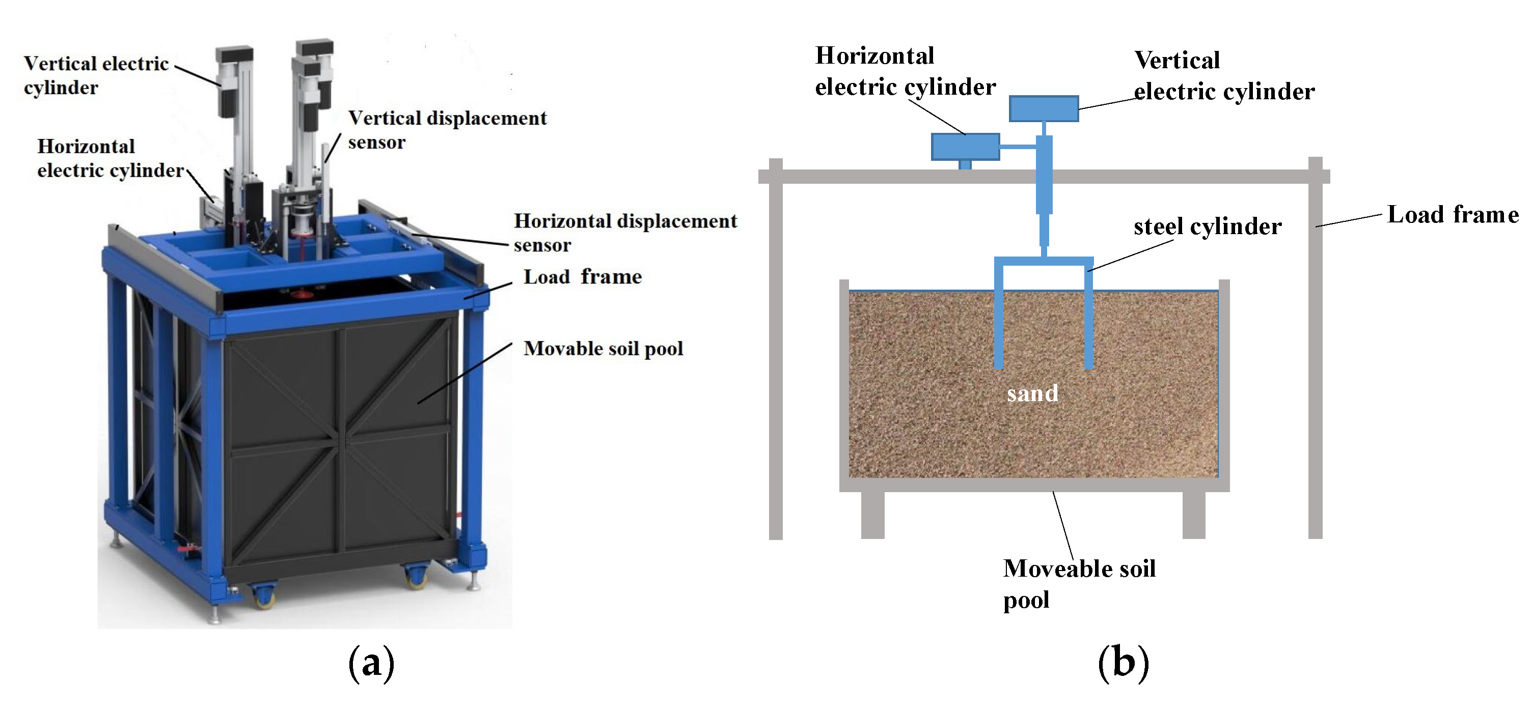
2.3. Test Setup and Device

The test device consists of a loading and positioning system and a measuring system, as shown in Figure 3. The loading and positioning system is mainly composed of a model slot, servo system, electric cylinder, I-beam, sliding guide rail and slide rail. The measuring system is mainly composed of a force sensor, displacement sensor, loading controller, dynamic data acquisition instrument and computer. The test device can accurately simulate the penetration process of the steel cylinder, record the penetration depth and force of the steel cylinder in real time and adjust the penetration speed of the steel cylinder. The test device consists of a movable soil pool with 600 × 600 × 700 mm in length, width and height, respectively.
To ensure good concentricity between the loading device and the cylinder during penetration, a ground hole with a diameter of 15 mm was designed at the center of the top of the cylinder. Before the test, the round hole was connected with the loading bar to ensure that the cylinder was uniformly stressed during penetration.

2.4. Test Program

The sliding guide was used to position the steel cylinder, fix it with bolts, debug the test instrument and control the steel cylinder to penetrate into the soil at the constant speed required during the test. Meanwhile, the penetration depth and force of the steel cylinder at different times were collected. When the cylinder penetrated to the predetermined depth, the penetration would stop, the pile shoe would be pulled out of the soil at a constant speed through program control and the test would end. The equipment would be removed and the sand would be backfilled, vibrated and cured again to ensure that the soil parameters in each test were similar.

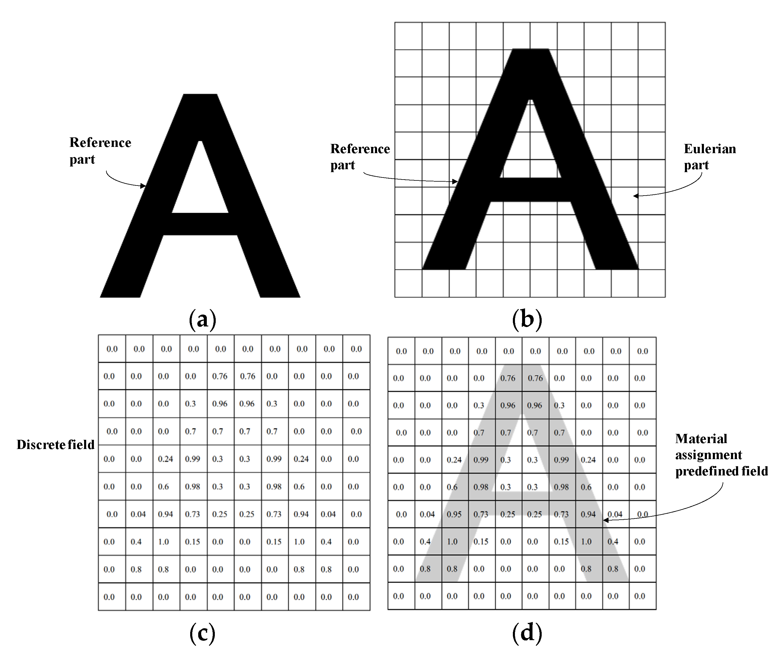
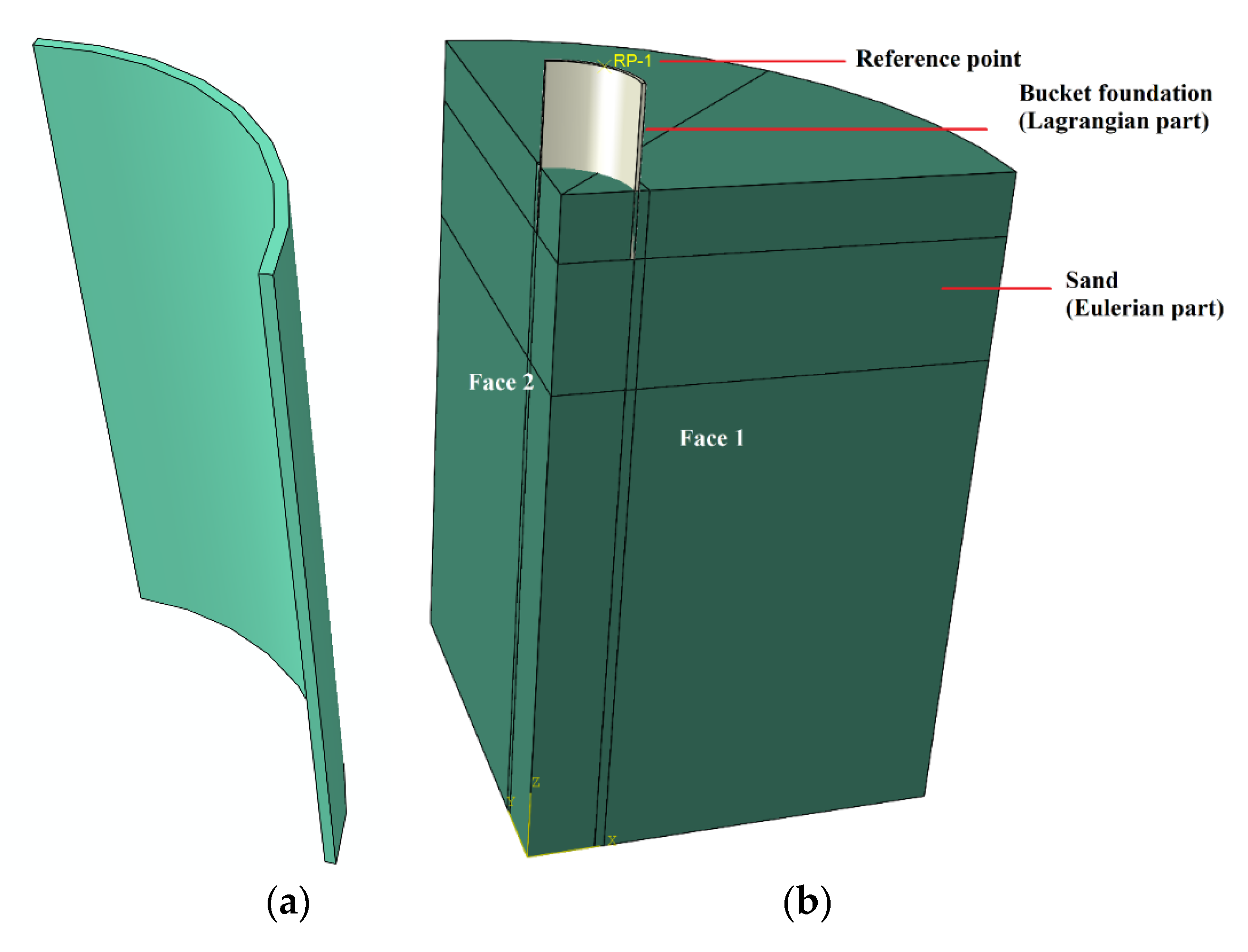
3. Finite Element Modelling

3DLDFE analyses were undertaken using the CEL approach with the commercially available software ABAQUS [35] since it is particularly well-suited to simulate the scenario of dynamic installation in the geotechnical field.
In the coupled Eulerian–Lagrangian finite element method, the deformation of Eulerian materials is based on the volume fraction tool. The value of volume fraction is between 0 and 1. Figure 4 shows the process of using the volume fraction tool. If a square is completely filled with materials, the Euler volume fraction (EVF) of the square is 1; if there is no material in a cell, its EVF = 0. If the total volume fraction of all materials in a square is less than 1, the remaining part of the square is automatically occupied by “empty” materials, which have neither strength nor mass. In the Euler grid, the volume fraction tool is used to disperse the reference volume used to describe the initial state and position of materials into the Euler volume, as shown in Figure 4.
The CEL analysis method was realized by means of dynamic analysis. The stability of this explicit algorithm is conditional. To ensure its numerical stability, the incremental step size must satisfy Δt. The critical time step cannot exceed Δtc, and the critical time step of each analysis step Δtc [35] is
Δ t c = L e c d
In Formula (1), Le is the dimension of the feature unit and cd is the expansion wave velocity.

3.1. Model Description

The model was based on the test model. The steel cylinder was modelled as a rigid body with a diameter D of 100 mm and a wall thicknesses t of 1 mm, 2 mm, 3 mm and 4 mm, corresponding to the thickness to diameter ratios t/D of 0.01, 0.02, 0.03 and 0.04, respectively.
The CEL model is demonstrated in Figure 5. The loading reference point was taken at the top and along the centerline of the cylinder, as illustrated in Figure 5b. To improve the computational efficiency, only a quarter model was used in this paper by taking advantage of the symmetry of the model. The soil domain had a radius of 3.5D (i.e., 350 mm) and a depth of 5.5D (i.e., 550 mm), ensuring a sufficient coverage without any boundary effect through the entire penetration analysis [35]. A void layer was prescribed with a height of 0.5D (i.e., 50 mm) above the surface of the soil. The soil bottom was fixed vertical displacements while the soil side with cycles only allowed vertical displacements, and faces 1 and 2 (in Figure 5b) are axisymmetric boundaries.
The entire soil domain was set as a Eulerian part, comprising linear reduced-integration Eulerian elements. A very fine mesh zone with a radius of 5D/8 (i.e., 62.5 mm) was set surrounding the steel cylinder with a minimum mesh size of t/6. The number of Eulerian elements was 5910464.
The internal and external side wall–soil interfaces used the general contact algorithm obeying the Coulomb friction law to specify the cylinder–soil interfaces. The interface friction coefficient was set as 0.2.

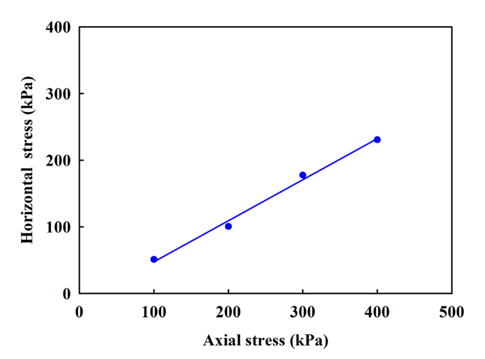
3.2. Soil Parameters

To more clearly and simply describe the flow characteristics of soil and the stress deformation characteristics of the foundation during the construction of bucket foundations, dry quartz sand was selected in this paper. The constitutive model of sand adopted the Mohr–Coulomb constitutive model. The failure criterion equation of the Mohr–Coulomb constitutive model can be expressed as follows:
σ 1 σ 3 f = 2 c cos φ + 2 σ 3 sin φ 1 sin φ
In Formula (2), σ1 and σ3 are the maximum and minimum principal stress, respectively; φ is the internal friction angle of the soil; c is the soil cohesion, kPa.
To obtain the constitutive model parameters of sand, a direct shear test was conducted, and the test results are shown in Figure 6. The internal friction angle φ and cohesion c of sand were 30° and 0 kPa, respectively.

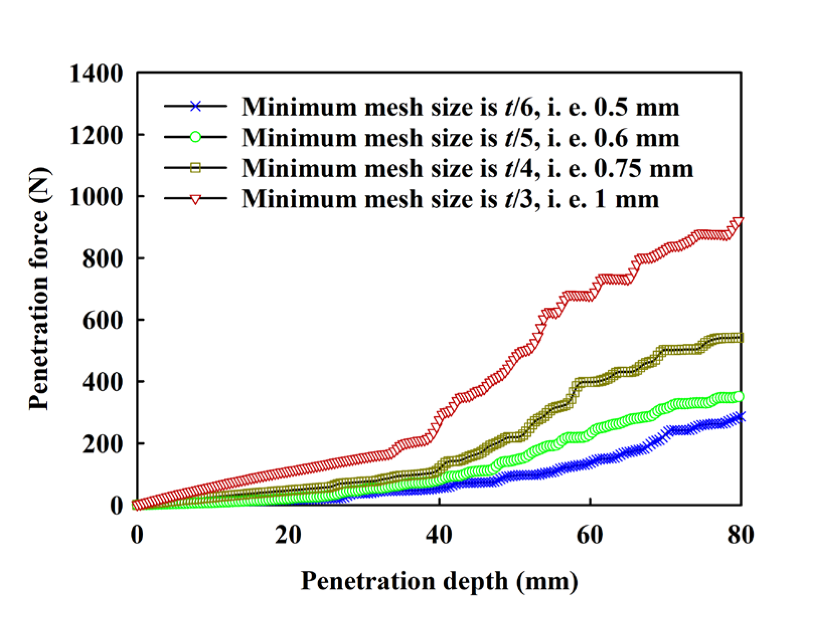
3.3. Mesh Sensitivity Analysis

Mesh sensitivity is a significant concern in coupled Eulerian-Lagrangian analysis. To validate mesh sensitivity, five different element sizes in the very fine mesh zone in Figure 5c were selected with sizes of t/6, t/5, t/4, and t/3 (t is the wall thickness of the steel cylinder). Figure 7 shows a group of comparisons of the penetration forces of steel cylinders with different mesh sizes and test results. It can be seen in the figure that when other conditions are the same, with an increase in the minimum element size of the model, the change trend of the penetration force with the penetration depth is basically the same, but the maximum value of the penetration force is different. With an increase in the minimum element size of the model, the penetration force increases gradually.

4. Results and Discussion

4.1. Model Test Results

To verify the subsequent numerical simulation results, this paper first carried out indoor model tests to obtain the changes in the penetration force of steel cylinders with different wall thicknesses during penetration. Figure 8 shows the relationship between the penetration depth and penetration force of steel cylinders with different wall thicknesses. It can be seen in the figure that with increasing penetration depth, the penetration force of the steel cylinder gradually increases. In the initial penetration process, the effect of wall thickness on the penetration force is small, but with increasing penetration depth, the effect of wall thickness on the penetration force gradually increases. After completion of the steel cylinder penetration, that is, when the penetration depth is 80 mm, the penetration force of the steel cylinder with a wall thickness of 1 mm was 147.98 N and the penetration force of the steel cylinder with a wall thickness of 4 mm was 514.50 N, which is 3.50 times the penetration force of the steel cylinder with a wall thickness of 1 mm.
According to the test results, a quadratic function can be used to describe the relationship between penetration force and penetration depth, namely,
F = e d p 2 + f d p
In Formula (3), F is the penetration force, dp is the penetration depth and e and f are the fitting parameters. See Table 1 for specific values.

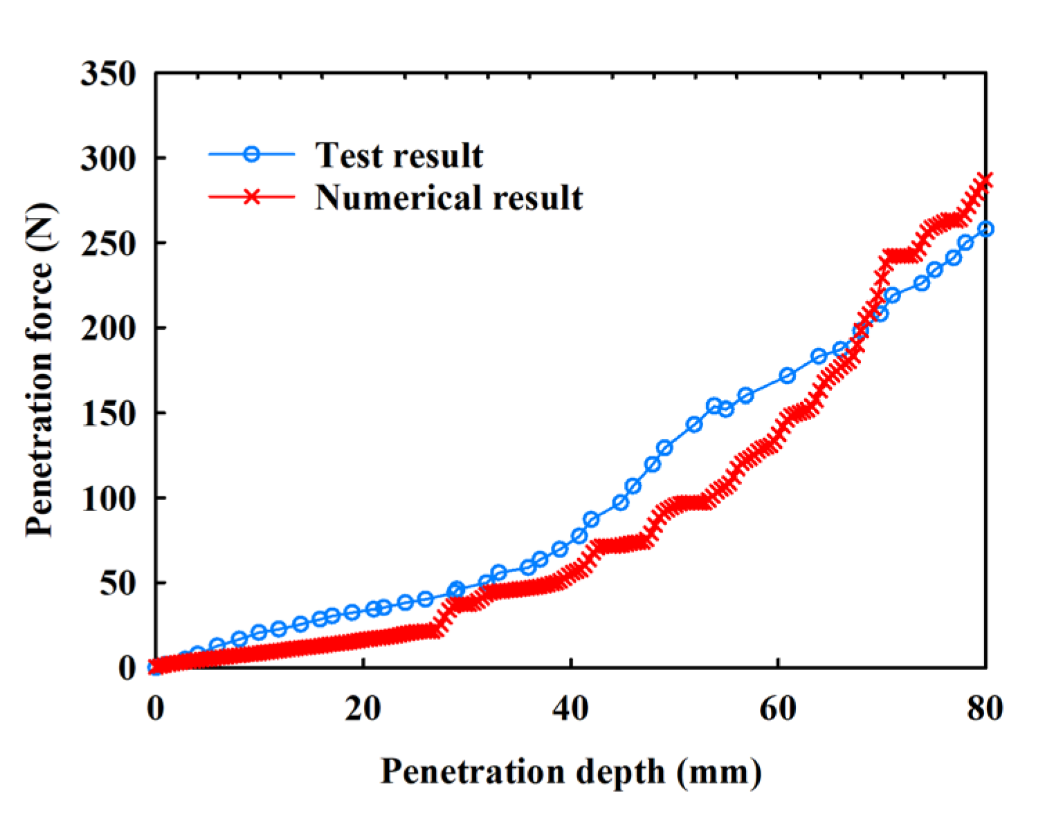
4.2. Verification of Numerical Model Results

It is hard to obtain the flow characteristics of soil during the penetration of steel cylinders by using indoor tests, and the accuracy of numerical simulation results is difficult to explain if the test results are verified. Therefore, before analyzing the soil flow characteristics and soil uplift, the numerical simulation results are verified by the penetration force measured in the test and the final uplift height of the soil. Figure 9 shows a comparison between the numerical simulation results and the test results when the wall thickness of the steel cylinder was 3 mm. As evident in Figure 9, when t/6 of the minimum element size is adopted, the penetration force against the penetration depth could be close to the test results. After the completion of the numerical simulation and the model test, the heights of soil heave inside the steel cylinder were 11.2 mm and 13.5 mm, respectively. According to the force and displacement curve of the steel cylinder and the soil uplift height, when the minimum grid size was t/6, the test results were very consistent with the numerical simulation results, and the minimum grid size in the subsequent numerical simulation was t/6.

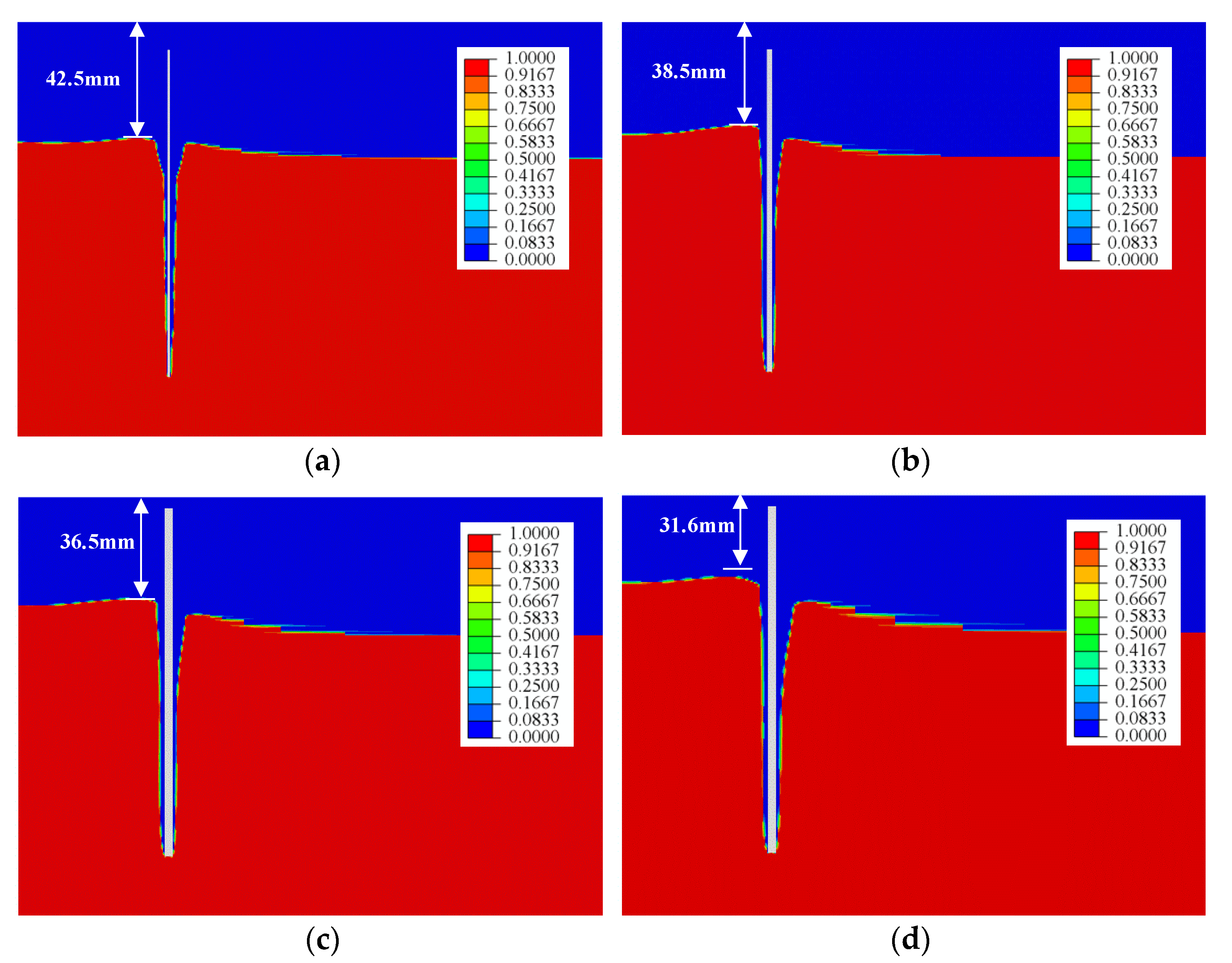
4.3. Influence of Wall Thickness on Soil Flow

In the process of steel cylinder penetration, the flow of soil in the steel cylinder has an important impact on the penetration force of the steel cylinder. Figure 10 shows the evolution of the soil flow during the penetration process of a steel cylinder, with four selected penetration depths dp of 20, 40, 60 and 80 mm. Figure 10 shows that with increasing penetration depth, the uplift height of the soil mass in the steel cylinder increased, indicating that the soil mass separated from the cylinder wall gradually flowed into the steel cylinder with the penetration of the steel cylinder. The uplift height of the soil inside and outside the steel cylinder was inconsistent. With an increase in the penetration depth, the difference in the uplift height of the soil inside the steel cylinder gradually increased, indicating that most of the soil discharged from the cylinder wall entered the cylinder, and only a small part flowed to the outside of the steel cylinder. This is basically consistent with an offshore bucket foundation investigation by Xiao et al. [36].

4.4. Influence of Wall Thickness on the Soil Heave in the Cylinder

During the penetration of a steel cylinder, the soil around the cylinder wall is discharged, causing the soil inside the cylinder to heave. For a steel cylinder with a closed top, the high uplift of the soil inside the cylinder may cause the penetration force of the steel cylinder to increase suddenly, so it is necessary to study the soil uplift inside the steel cylinder. Figure 11 shows the soil heave height in a steel cylinder with different wall thicknesses after penetration. The height indicated in the figure is the distance from the highest point of soil uplift to the top of the empty layer, that is, the actual uplift height of the soil is equal to the height of the empty layer of the soil during modelling (that is, 50 mm) minus the data indicated in the figure. It can be seen in the figure that with an increase in the wall thickness of the steel cylinder, the uplift height of the soil in the cylinder gradually increased. When the wall thickness increased from 1 mm to 4 mm, the uplift height of the soil in the cylinder increased from 9.1 mm to 23.7 mm.

5. Conclusions

To study the influence of wall thickness of a steel cylinder on its penetration process, this paper used a model test and the CEL method. The research results are as follows:
(1)
It can be seen from the test results that the penetration force of a steel cylinder increases gradually with increasing penetration depth, and the influence of wall thickness on the penetration force increases gradually. We established the relationship between the penetration resistance of steel cylinders and the penetration depth under different wall thicknesses. Through the relationship between the two, it can be seen that as the penetration depth increases, the rate of increase in penetration resistance increases.
(2)
From the numerical simulation results, it can be seen that wall thickness has a significant impact on the uplift of soil. With an increase in wall thickness of a steel cylinder, the uplift height of the soil inside the steel cylinder gradually increases. When the wall thickness increases from 1 mm to 4 mm, the uplift height of the soil inside the steel cylinder increases 2.6 times.
(3)
In this paper, the penetration process of steel cylinders in sandy soil foundations was studied through indoor tests and numerical simulations, and the penetration force and soil uplift during the penetration process of steel cylinders were studied. According to the comparative analysis of the two, the uplift of soil in the barrel increases with an increase in wall thickness. The operative volume ratio of the soil in the bucket is calculated by means of a formula, and it was found that it has a power function relationship with wall thickness. The research results can provide a reference for the application of penetration force during the penetration process of steel cylinders.

Author Contributions

Conceptualization, W.X. and H.R.; data curation, W.X. and P.J.; formal analysis, W.X. and H.R.; methodology, W.X. and P.J.; writing—original draft preparation, W.X.; writing—review and editing, H.R. All authors have read and agreed to the published version of the manuscript.

Funding

This research was funded by two grants from the National Science Foundation of China (51979128).

Institutional Review Board Statement

Not applicable.

Informed Consent Statement

Not applicable.

Data Availability Statement

The data used to support the findings of the study are available from the corresponding author upon request.

Acknowledgments

The authors appreciate the comments and suggestions by the editors and anonymous reviewers.

Conflicts of Interest

The authors declare no conflict of interest.

References

  1. Sparrevik, P. Suction Pile Technology and Installation in Deep Waters. In Proceedings of the Annual Offshore Technology Conference, Houston, TX, USA, 6–9 May 2002; pp. 2171–2179. [Google Scholar]
  2. Koh, K.X.; Hossain, M.S.; Kim, Y. Installation and Monotonic Pullout of a Suction Caisson Anchor in Calcareous Silt. J. Geotech. Geoenviron. Eng. 2017, 143, 04016098. [Google Scholar] [CrossRef]
  3. Andersen, K.H.; Murff, J.D.; Randolph, M.F.; Clukey, E.; Erbrich, C. Suction anchors for deepwater applications. In Frontiers in Offshore Geotechnics, ISFOG 2005, Proceedings of the 1st International Symposium on Frontiers in Offshore Geotechnics, Perth, WA, Australia, 19–21 September 2005; ISFOG: Perth, Australia, 2005; pp. 3–30. [Google Scholar]
  4. Zhang, J.H.; Zhang, L.M.; Lu, X.B. Centrifuge modeling of suction bucket foundations for platforms under ice-sheet-induced cyclic lateral loadings. Ocean Eng. 2007, 34, 1069–1079. [Google Scholar] [CrossRef]
  5. Zhang, P.; Ding, H. Bearing capacity of the bucket spudcan foundation for offshore jack-up drilling platforms. Pet. Explor. Dev. 2011, 38, 237–242. [Google Scholar] [CrossRef]
  6. Villalobos, F.A.; Byrne, B.W.; Houlsby, G.T. Model testing of suction caissons in clay subjected to vertical loading. Appl. Ocean Res. 2010, 32, 414–424. [Google Scholar] [CrossRef]
  7. Jijian, L.; Hongyan, D.; Puyang, Z.; Rui, Y. Design of Large-Scale Prestressing Bucket Foundation for Offshore Wind Turbines. Trans. Tianjin Univ. 2012, 18, 79–84. [Google Scholar]
  8. Achmus, M.; Akdag, C.T.; Thieken, K. Load-bearing behavior of suction bucket foundations in sand. Appl. Ocean Res. 2013, 43, 157–165. [Google Scholar] [CrossRef]
  9. Byrne, B.; Houlsby, G.; Martin, C.; Fish, P. Suction caisson foundations for offshore wind turbines. Wind Eng. 2002, 26, 145–155. [Google Scholar] [CrossRef]
  10. Gavin, K.; Igoe, D.; Doherty, P. Piles for offshore wind turbines: A state-of-the-art review. Proc. Inst. Civ. Eng. Geotech. Eng. 2011, 164, 245–256. [Google Scholar] [CrossRef]
  11. Houlsby, G.T.; Kelly, R.B.; Huxtable, J.; Byrne, B.W. Field trials of suction caissons in sand for offshore wind turbine foundations. Geotechnique 2005, 55, 287–296. [Google Scholar] [CrossRef]
  12. Andersen, K.H.; Jostad, H.P. Foundation design of skirted foundations and anchors in clay. In Proceedings of the Annual Offshore Technology Conference, Houston, TX, USA, 3–6 May 1999; Volume 1, pp. 383–392. [Google Scholar]
  13. Randolph, M.F.; Gaudin, C.; Gourvenec, S.M.; White, D.J.; Boylan, N.; Cassidy, M.J. Recent advances in offshore geotechnics for deep water oil and gas developments. Ocean Eng. 2011, 38, 818–834. [Google Scholar] [CrossRef]
  14. Andresen, L.; Jostad, H.P.; Andersen, K.H. Finite Element Analyses Applied in Design of Foundations and Anchors for Offshore Structures. Int. J. Geomech. 2011, 11, 417–430. [Google Scholar] [CrossRef]
  15. Chu, J.; Yan, S.W.; Li, W. Innovative methods for dike construction-An overview. Geotext. Geomembr. 2012, 30, 35–42. [Google Scholar] [CrossRef]
  16. Chen, W.; Zhou, H.; Randolph, M.F. Effect of Installation Method on External Shaft Friction of Caissons in Soft Clay. J. Geotech. Geoenviron. Eng. 2009, 135, 605–615. [Google Scholar] [CrossRef]
  17. Chen, F.; Lian, J.; Wang, H.; Liu, F.; Wang, H.; Zhao, Y. Large-scale experimental investigation of the installation of suction caissons in silt sand. Appl. Ocean Res. 2016, 60, 109–120. [Google Scholar] [CrossRef]
  18. Zhang, P.; Guo, Y.; Liu, Y.; Ding, H. Experimental study on installation of hybrid bucket foundations for offshore wind turbines in silty clay. Ocean Eng. 2016, 114, 87–100. [Google Scholar] [CrossRef]
  19. Stapelfeldt, M.; Bienen, B.; Grabe, J. The influence of the drainage regime on the installation and the response to vertical cyclic loading of suction caissons in dense sand. Ocean Eng. 2020, 215, 107105. [Google Scholar] [CrossRef]
  20. Guo, W.; Chu, J. Suction caisson installation in shallow water: Model tests and prediction. In Proceedings of the 18th International Conference on Soil Mechanics and Geotechnical Engineering: Challenges and Innovations in Geotechnics, ICSMGE, Paris, France, 2–6 September 2013; Volume 3, pp. 1999–2002. [Google Scholar]
  21. Gaudin, C.; O’Loughlin, C.D.; Hossain, M.S.; Randolph, M.F.; Colliat, J.L. Installation of suction caissons in Gulf of Guinea clay. In Physical Modelling in Geotechnics, Proceedings of the 8th International Conference on Physical Modelling in Geotechnics 2014, ICPMG, Perth, Australia, 14–17 January 2014; CRC Press: Boca Raton, FL, USA, 2014; Volume 1, pp. 493–499. [Google Scholar]
  22. Zhu, X.J.; Li, W.S.; Fei, K. Jacking penetration resistance and mechanical characteristics of bucket foundations in sand. Bull. Eng. Geol. Environ. 2020, 79, 1–10. [Google Scholar] [CrossRef]
  23. Houlsby, G.T.; Byrne, B.W. Design procedures for installation of suction caissons in clay and other materials. Proc. Inst. Civ. Eng. Geotech. Eng. 2005, 158, 75–82. [Google Scholar] [CrossRef]
  24. Jin, Z.; Yin, Z.Y.; Kotronis, P.; Jin, Y.F. Numerical Analysis of a Suction Bucket Penetrating in Sand with a Combined Lagrangian-SPH Approach. Procedia Eng. 2017, 175, 189–196. [Google Scholar] [CrossRef]
  25. Zhou, H.; Randolph, M.F. Large deformation analysis of suction caisson installation in clay. Can. Geotech. J. 2006, 43, 1344–1357. [Google Scholar] [CrossRef]
  26. Harireche, O.; Naqash, M.T.; Farooq, Q.U. A full numerical model for the installation analysis of suction caissons in sand. Ocean Eng. 2021, 234, 109173. [Google Scholar] [CrossRef]
  27. Harireche, O.; Mehravar, M.; Alani, A.M. Soil conditions and bounds to suction during the installation of caisson foundations in sand. Ocean Eng. 2014, 88, 164–173. [Google Scholar] [CrossRef]
  28. Hu, Y.; Randolph, M.F. A practical numerical approach for large deformation problems in soil. Int. J. Numer. Anal. Methods Geomech. 1998, 22, 327–350. [Google Scholar] [CrossRef]
  29. Vásquez, L.F.G.; Maniar, D.R.; Tassoulas, J.L. Installation and Axial Pullout of Suction Caissons: Numerical Modeling. J. Geotech. Geoenviron. Eng. 2010, 136, 1137–1147. [Google Scholar] [CrossRef]
  30. Maniar, D.R.; Vásquez, L.F.G.; Tassoulas, J.L. Installation and pullout of suction caissons: Finite-element simulation. In Proceedings of the OMAE03 22nd International Conference on Offshore Mechanics and Arctic Engineering, Cancun, Mexico, 8–13 June 2003; pp. 1–2. [Google Scholar]
  31. Senders, M.; Randolph, M.F. CPT-Based Method for the Installation of Suction Caissons in Sand. J. Geotech. Geoenviron. Eng. 2009, 135, 14–25. [Google Scholar] [CrossRef]
  32. Klinkvort, R.T.; Sturm, H.; Andersen, K.H. Penetration Model for Installation of Skirted Foundations in Layered Soils. J. Geotech. Geoenviron. Eng. 2019, 145, 04019085. [Google Scholar] [CrossRef]
  33. Grecu, S.; Ibsen, L.B.; Barari, A. Winkler springs for axial response of suction bucket foundations in cohesionless soil. Soils Found. 2021, 61, 64–79. [Google Scholar] [CrossRef]
  34. Niu, Q.L.; Song, G.; Cui, S.Y.; Kou, B.B.; Tian, Z.Y.; Tian, Y.Y. Calculation and analysis of penetration force on offshore suction bucket jacket foundation. Drill. Eng. 2023, 50, 31–38. [Google Scholar]
  35. Systemes, D. Abaqus Analysis Users’ Manual; Simula Corp: Providence, RI, USA, 2010. [Google Scholar]
  36. Xiao, Z.; Fu, D.; Zhou, Z.; Lu, Y.; Yan, Y. Effects of strain softening on the penetration resistance of offshore bucket foundation in nonhomogeneous clay. Ocean Eng. 2019, 193, 106594. [Google Scholar] [CrossRef]
Figure 1. Steel cylinder. (a) Sketch; (b) photograph.
Applsci 13 09417 g001
Figure 2. Grading curve of sand.
Applsci 13 09417 g002
Figure 3. Test device. (a) Physical drawing; (b) schematic diagram.
Applsci 13 09417 g003
Figure 4. Fluid volume method. (a) Reference part; (b) Eulerian part and reference part; (c) discrete field; (d) predefined material assignment field.
Applsci 13 09417 g004
Figure 5. CEL model. (a) Steel cylinder model; (b) 3D calculation model; (c) mesh of the 3D CEL model (side view); (d) mesh of the 3D CEL model (top view).
Applsci 13 09417 g005aApplsci 13 09417 g005b
Figure 6. Direct shear test result of the sand.
Applsci 13 09417 g006
Figure 7. Relationship between penetration forces and penetration depth using different element size (minimum element size hmin of t/8, t/6, t/4, t/2, t).
Applsci 13 09417 g007
Figure 8. Relationship between the penetration depth and penetration force of steel cylinders with different wall thicknesses.
Applsci 13 09417 g008
Figure 9. Comparison between the numerical results and the test results (relation curve between penetration force and penetration depth, wall thickness t = 3 mm).
Applsci 13 09417 g009
Figure 10. Evolution of the soil flow during the installation process. (a) Penetration depth of 20 mm; (b) penetration depth of 40 mm; (c) penetration depth of 60 mm; (d) penetration depth of 80 mm.
Applsci 13 09417 g010
Figure 11. Soil heave height in a steel cylinder with different wall thicknesses after penetration: (a) t = 1 mm; (b) t = 2 mm; (c) t = 3 mm; (d) t = 4 mm.
Applsci 13 09417 g011
Table 1. Fitting results of Formula (3).
Wall Thickness t/mmefR2
10.02150.03530.9804
20.02940.35160.9891
30.03070.80020.9919
40.07470.55940.9974
Disclaimer/Publisher’s Note: The statements, opinions and data contained in all publications are solely those of the individual author(s) and contributor(s) and not of MDPI and/or the editor(s). MDPI and/or the editor(s) disclaim responsibility for any injury to people or property resulting from any ideas, methods, instructions or products referred to in the content.

