Review

Seismic Exploration Methods for Structural Studies and for Active Fault Characterization: A Review

by
Pier Paolo G. Bruno
1,2
1
Dipartimento di Scienze della Terra, Ambiente e Risorse, Università degli Studi di Napoli “Federico II”, 80126 Napoli, Italy
2
Aeronomia e Geofisica Ambientale, Sezione di Geomagnetismo, Istituto Nazionale di Geofisica e Vulcanologia, 00143 Roma, Italy
Appl. Sci. 2023, 13(16), 9473; https://doi.org/10.3390/app13169473
Submission received: 1 June 2023 / Revised: 7 August 2023 / Accepted: 12 August 2023 / Published: 21 August 2023
(This article belongs to the Special Issue Advances in Structural Geology)

Abstract

:
In this paper, seismic exploration methods are reviewed with a particular emphasis on the use of the reflection seismology to investigate the subsurface structures and characterize active faults. The paper provides a descriptive overview, intended for a non-specialist audience, of the methods and of their recent developments aimed at improving the resolution, accuracy, and computational efficiency of seismic imaging. Techniques such as seismic ray tomography, full-waveform inversion and pre-stack depth migration are briefly introduced, highlighting their potential applications in structural geology studies. The main seismic attributes that have become increasingly important in the interpretation of faults and fractures are also presented, along with some examples of application. Finally, some case studies of active fault characterization are discussed. From these examples, the crucial role played nowadays by the seismic exploration methods for structural studies and for active fault characterization is evident.

1. Introduction

Seismic exploration methods have long been used in geophysical studies to investigate the subsurface structure and the properties of geological formations. Seismic methods provide key subsurface information for structural geologists and have become highly effective in imaging even complex geological settings. Among seismic methods, reflection seismology, that has revolutionized our understanding of the earth’s subsurface, is certainly the main tool of seismic imaging and the primary technique used in energy exploration: it was initially developed in the 1920s for the petroleum industry. Over the years, this method has undergone continuous improvements in data acquisition, signal enhancement, and geological interpretation, resulting in significant advances [1].
As documented by Sheriff and Geldart [2], originally, the reflection technique involved detonating a dynamite charge in the ground and recording the seismic waves reflected from subsurface interfaces using a linear array of geophones, consisting of several dozen units. The seismograms were initially stored on photographic paper. In regions where conditions were favorable, geophysicists could track the same reflected phase over an extended distance beyond what the receiver spread covered for a single record. In such instances, they aligned the records adjacent to each other to analyze the subsurface. However, in numerous regions, particularly those underwater, the noise generated by the source (e.g., reverberations and multiple reflections) dominated the primary reflections, making visual identification difficult. To address the challenge of removing source-generated noise, the major oil and geophysical companies of the time provided sponsorship to the MIT Geophysical Analysis Group for the development of digital-processing techniques [3,4,5,6]. This was the first-ever effort to convert an industry from analog to digital, and exploration geophysics was at the forefront of this transformation. Geophysicists coined the term “digital revolution” to describe this shift [6]. Such was the rapid pace of advancements that, by the close of the 1950s, the seismic reflection method had become the oil industry’s primary geophysical methodology, providing detailed images of sedimentary basins and faults. The development of three-dimensional (3D) methods in the late 1970s began to resolve the interpretation ambiguities inherent in interpolating between seismic profiles and provided significant noise reduction [2]. Early 3D surveys revealed so much structural and stratigraphic detail that the method started growing very rapidly.
Among all geophysical methods available today, reflection seismology certainly provides the highest resolution, making it a valuable tool for a wide range of applications. However, processing seismic reflection data is a computationally intensive process. The high cost associated with acquiring and processing seismic reflection data, especially for 3D imaging, has traditionally limited its use to the oil industry. Nevertheless, advances in microelectronics in the early 1980s enabled the development of cost-effective seismographs and microcomputers, opening new possibilities for reflection seismology in a range of fields, from deep crustal exploration to civil engineering site investigations [7]. As a result, this technique is now used successfully in various fields, including deep crustal exploration, groundwater resource assessment, and civil engineering site investigations [8].
The interpretation of seismic reflection data is a fundamental step to infer the subsurface characteristics of sedimentary basins in terms of stratigraphy and structures [9,10,11]. Three-dimensional (3D) seismic data provide a means for structural geologists to examine structural styles across the studied volume and to map structures in detail, facilitating the development of hypotheses about the factors controlling them [12]. The recent use of high-resolution seismic exploration methods for near-surface active fault characterization is very interesting, as the identification and characterization of active faults are critical to studies of regional seismic hazard [13,14]. To perform probabilistic seismic hazard analysis, it is fundamental to develop seismic source models, by identifying seismogenic faults and finding the main earthquakes linked to them. Those tasks are crucial and are performed using geological, historical, seismological, and other geophysical data [15]. Seismic source models are used to determine the characteristic magnitudes and frequencies of earthquakes for each seismogenic source. However, historical and instrumental records of seismic activity may not provide a complete picture of the earthquake cycle, since in many areas, these records are typically much shorter than the recurrence times of the largest earthquakes [16]. To address this limitation, the integration of very-high resolution geophysical imaging methods and paleoseismological techniques have become critical tools in the identification of major seismogenic faults that have disrupted the uppermost few meters of the ground (see Maraio et al. [17] and references therein).
In this review article, I aim to present to non-specialists the methods of seismic exploration that are more valuable for structural studies and active fault characterization without delving into the mathematical background. In doing so, I hope to offer an accessible introduction to those methods to geologists and other professionals who may lack a strong mathematical background but wish to grasp the underlying concepts. For those seeking more in-depth information, I will provide references to the fundamental scholarly literature. Additionally, I will explore recent advancements in seismic reflection imaging, and I will discuss their applications. I will specifically focus the attention on the techniques used to enhance structural features, in particular faults and fractures. For each technique, I will provide a concise overview of the fundamental concepts, reviewing recent developments and showcasing several examples of its significance including active fault characterization.

2. Review of Reflection Seismology

Reflection seismology is a geophysical method of investigation of the subsurface at different scales (from metric to crustal) that allows retrieving with high detail the characteristics and geometry of the rock formations underlying the earth’s surface [18]. Typically, it is based on the analysis of the response of the subsurface layers to a seismic disturbance generated at the earth’s surface by an impulsive or vibratory source. It was originally developed for sedimentary basins, but it is nowadays applied in many other environments, from volcanic areas to intrusive domains [2]. The principles of reflection seismology are very similar to those of sonar and radar: an artificial seismic source releases energy at the surface; the energy propagates inside the earth in the form of seismic waves which are reflected back toward the earth’s surface when discontinuities are encountered. To produce a seismic image, the data are intensively processed, the intensity of the processing depending mainly: on the near-surface conditions below the investigated area; on the complexity of the structures to be imaged and finally on the signal-to-noise ratio of the acquired data. In continental environments, seismic data are generally affected by greater noise, which is in part caused by the environment but also linked to near-surface heterogeneities. For example, across fault zones, very pronounced lateral variations of seismic velocity conflict with the assumptions of horizontally stratified earth and constant velocity implied by the method [19]. In the same way, seismic exploration in volcanic environments is strongly hindered by the presence of highly heterogeneous material which complicates wave propagation by absorbing and scattering most of the energy released by the source. Generally, in those environments, the seismic energy is fragmented into a series of seismic phases (such as surface waves and guided waves, head-waves and diffractions) that obliterate the reflected phases of interest and inevitably worsen the quality of the final seismic image; therefore, data will require additional processing steps. Conversely, in marine environments, data processing is simplified by the presence of a homogeneous medium (i.e., the water column) at the surface.
On land, the recording device is made by one or more vibratory sources organized in patterns and by a series of geophones placed regularly along a line (or several lines for 3D acquisitions). At sea, the most used source is the airgun (see Caldwell and Dragoset, [20] and references therein). The utilization of airguns is presently a topic of controversy due to the potential effects on marine life, especially cetaceans, which are still being investigated [21]. As a result, several countries have imposed limitations on the use of this source.
As previously mentioned, seismic reflection processing is data dependent, i.e., there is no flow valid for all data, but the processing stream must be adapted to the individual dataset. For example, the static corrections (necessary to remove elevation differences between sources and geophones and the effects of surface velocity anomalies) are fundamental in continental settings but generally not performed in a marine environment. However, three analysis procedures are always applied to seismic data: deconvolution, migration, and velocity analysis [19]. Deconvolution (which is divided into spiking and predictive) is a process which allows to increase the temporal resolution of the seismic trace by removing the source features embedded in the recorded seismogram. In its predictive implementation, it also allows to attenuate multiple reflections, thus improving the interpretability of the data. Velocity analysis plays a crucial role in seismic data processing: in classical applications, as described by Yilmaz [19], it becomes essential to estimate velocities to convert seismic data from the pre-stack to the post-stack domain. The pre-stack domain consists of seismic traces gathered by their common point of reflection or CMP. By performing velocity analysis, the seismic data can be transformed into the post-stack domain, which emulates a zero-offset section obtained using a linear source (or a planar source for 3D experiments). Generally, velocities are estimated by picking the maxima of a semblance function computed across hyperbolic trajectories on selected CMP gathers [22].
Finally, migration [19] is a fundamental step to overcome the assumption of horizontally stratified earth of the CMP method, which obviously does not work in the presence of dipping structures. Migration is a computationally expensive process that allows repositioning dipping reflected events to their correct spatial and temporal locations, thus removing the distortions present in the stack image in case of non-horizontal features. Migration is a fundamental process in seismic data processing that involves relocating seismic events to their true positions in the subsurface [2,19]. The technique removes the effects of wave propagation from the recorded seismic data to correct the spatial positioning of reflection events, thereby increasing the lateral resolution of the resulting image [23]. The primary goal of migration is to produce a stacked section or volume that resembles a geologic cross-section.
At the end of the processing phase, 2D or 3D images are available to be used in various fields of geological sciences and applications. However, these images need an interpretation, as they are a geophysical representation of the subsurface; therefore, they are subject to several limitations and uncertainties, as discussed by Sheriff and Geldart, [2]. For example, reflectivity can be affected by a wide range of factors, such as the heterogeneity in the distribution velocity and density of the subsurface materials, the geometry of the reflectors, presence of fluids, presence of noise and other artifacts in the data. Different types of noise can make it difficult to distinguish between real geological features and artifacts. For example, multiple reflections from shallow high-impedance interfaces, which could not be entirely removed during the processing phase, may obscure deeper reflectors, or they can be misinterpreted as true reflectors. Similarly, the presence of gas or other fluids in the subsurface can modify the reflectivity or deteriorate the seismic image. To overcome these challenges, a variety of interpretive techniques have been developed to analyze seismic reflection data and extract meaningful information about the subsurface (see Badley, [10]). These techniques can include mere visualization tools as well as more quantitative methods such as waveform inversion and seismic attribute analysis that will be discussed in the following parts.

3. Developments in Seismic Imaging

Developments in seismic imaging have focused on improving the resolution, accuracy and computational efficiency of imaging (e.g., Lailly, [24]; Tarantola, [25]; Virieux and Operto, [26]; Biondi and Almomin, [27]). One major area of advancement has been in the improvement of seismic acquisition techniques and in the use of machine learning techniques to increase the accuracy and speed of seismic data processing and interpretation [28,29]. Below, I will briefly discuss some of these recent developments that are more pertinent for structural studies and for active fault characterization.

3.1. Dense-Wide Aperture Acquisition

The dense-wide aperture (WA) technique is a field data acquisition technique that involves deploying many closely spaced seismic sensors with a large array aperture [30]. One advantage of the dense-wide aperture technique is its ability to image complex subsurface structures, which can be difficult to image using narrow-aperture acquisition methods [31]. Additionally, by integrating seismic tomography and reflection seismology, dense WA arrays allow for the better detection of small-scale features such as thin layers and small faults [32].
The geometry of dense WA differs from the common midpoint narrow aperture reflection surveying as it captures multifold reflection data covering a wide range of offsets, including deep-penetrating refracted waves suitable for first-arrival travel-time tomography [32]. An example is pictured in Figure 1. Data recorded by dense WA arrays are attractive because they contain more seismic phases than those recorded by traditional arrays and therefore can be processed using several imaging methods rather than only one, reducing the need of further field data surveys. For instance, dense WA profiles allow the use of refraction tomography or full-waveform inversion for estimating the seismic velocity models. This estimation is essential for achieving a reliable depth migration of seismic reflection data [33]. Moreover, dense WA arrays allow valuable structural information to be obtained from different imaging techniques, facilitating the integration of seismic tomography and seismic reflection data into the interpretation phase [31]. Ultimately, this integration can lead to an improvement of seismic interpretation.

3.2. Seismic Ray Tomography

Seismic ray tomography [35,36] is a powerful technique used to image the subsurface structure of the earth. It involves the use of an iterative inversion procedure which computes the theoretical traveltimes of seismic waves traced within an “a priori” model of subsurface and compares them with the traveltimes observed during an actual seismic survey [37]. The inversion procedure aims at minimizing the traveltime differences by iteratively updating the seismic velocities of the “a priori” model [38]. The method produces images of the distribution of P-wave and/or S-wave velocity in the subsurface, with velocity variations highlighting changes in rock properties, such as lithology, porosity, and fluid content [39].
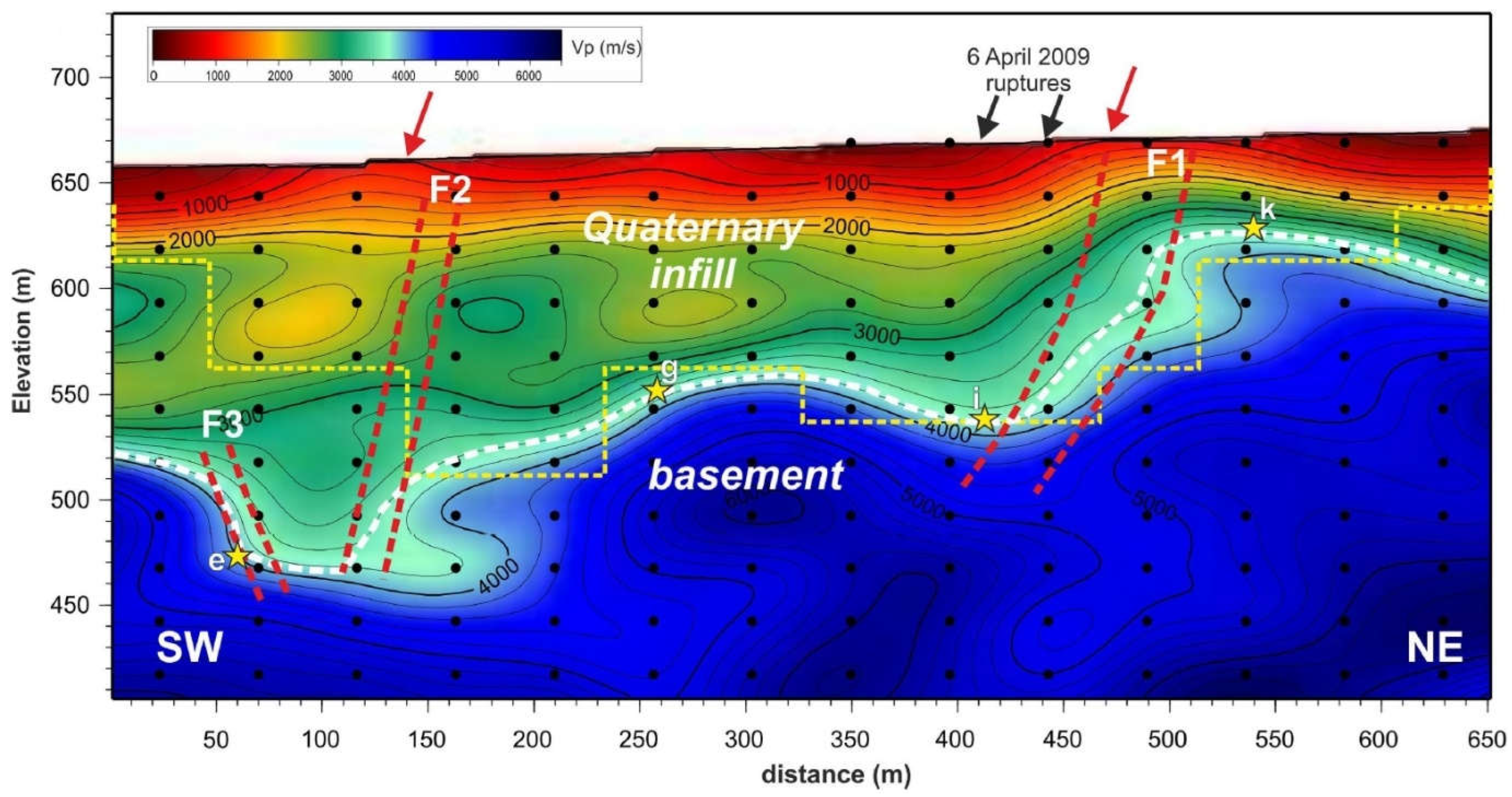
When refracted waves (i.e., first arrivals) are used, the method is also called refraction tomography or First Arrival Tomography (FAT). One of the advantages of FAT, when applied to data recorded by dense WA arrays, is its ability to provide high-resolution images of the subsurface at relatively shallow depths [32], making this technique well-suited for imaging near-surface seismogenic faults, as demonstrated by several studies. For example, Buddensiek et al. [40] verified the capability of FAT in identifying faults across the Wasatch Fault Zone near Mapleton, Utah. On their tomograms, faults were identified by imaging the associated colluvial wedges, which were seen as low-velocity zones in the tomogram. Similarly, Improta et al. [41] and Villani et al. [42] estimated high-resolution Vp models of the Middle Aterno basin, in central Italy, by applying multi-scale non-linear tomography to data recorded by dense WA profiles acquired on the hanging wall of the Paganica-S. Demetrio Fault (see Figure 2). This fault is the source of the 6 April 2009 (Mw 6.1) L’Aquila normal-faulting earthquake.
However, seismic ray tomography does have some limitations. One challenge is that the accuracy of the results can be influenced by the complexity of the subsurface geology, which can make it difficult to model accurately seismic wave propagation [40]. Moreover, since the method uses a smooth model parameterization, it is unable to detect sharp stratigraphic and structural discontinuities. Discontinuities as faults can only be inferred through the analysis of velocity patterns and gradients. Finally, resolution decreases rapidly with depth at the edges of the velocity models, due to poor ray sampling [43].

3.3. Full-Waveform Inversion

Full-Waveform Inversion (FWI) has gained increasing popularity in the recent years. Differently from seismic ray tomography, FWI utilizes the entire seismic wavefield to generate high-resolution images of the subsurface, providing greater details about the physical properties of the subsurface. FWI is an iterative inversion technique that seeks to minimize the difference between observed and synthetic wavefields by iteratively updating the model parameters [26]. FWI typically involves several key steps which are similar to those of seismic ray tomography. First, an initial model of the subsurface is created based on existing data and geological knowledge. Next, synthetic wavefields are modeled into the initial model, and the resulting waveforms are compared with the recorded data. The differences between the observed and synthetic data are then minimized by updating the initial model parameters. Steps two and three are applied iteratively until an optimal match between synthetic and recorded waveforms is achieved [26]. When the method works, it provides high-resolution images of the subsurface, higher than those from seismic ray tomography, therefore adding valuable insights for the interpretation.
One of the challenges of FWI lies in its computational intensity, as the method involves the inversion of the entire seismic wavefield. To overcome this challenge, various techniques have been proposed, such as using gradient-based optimization methods [26]. In addition, constructing a reliable initial model for FWI continues to be a pressing concern, as controlled-source experiments cannot yet capture very low frequencies, which are needed to provide a reliable estimate of the initial model [44]. The accuracy of results is heavily influenced by the initial model, as they depend on inversion non-uniqueness and local-search optimization techniques. In the case of near-surface FWI, the starting model’s dependence can be especially problematic due to the complicated nature of the recorded seismic wavefield (i.e., a combination of surface waves and body waves) and the possibility of significant heterogeneity over short distances, see Brossier et al. [45].
In the quest for developing a suitable starting model for FWI, various approaches have been explored. One such approach, commonly employed in the oil and gas exploration industry, involves the integration of reflection tomography and migration-based velocity analysis, as described by Woodward et al. [46]. An alternative method, which offers a more automated and FWI-oriented approach to constructing accurate starting models, uses first-arrival traveltime tomography [30]. Additionally, another promising option to tackle this challenge in near-surface environments involves the use of neural networks to build initial models specifically fitted for 2D elastic FWI (e.g., [28,47,48]).
Due to the complexity of the near-surface, FWI has primarily been utilized to study subsurface structures on a larger scale. For instance, in a study by Dessa et al. [49], FWI was implemented for a seismic investigation of the eastern Nankai subduction system (Japan) at a crustal scale, using dense ocean bottom seismic data. By adopting this method, Dessa et al. [49] were able to accurately quantify seismic velocities to an unprecedented degree of resolution (Figure 3). Their findings indicate the presence of compressive tectonic features within both the subducting oceanic crust and the backstop. Furthermore, Dessa et al. [49] observed velocity anomalies along major faults and structural discontinuities at depth, providing evidence for the existence of fluids and weakened materials and suggesting a possible coseismic slip partitioning structure.
While the majority of FWI applications in the oil industry traditionally focus on analyzing geological structures at intermediate scales, in particular for the subsalt imaging (e.g., Shen et al. [50]), there is an emerging use of FWI applications in the near-surface, as evidenced by the recent scholarly literature. For instance, Adamczyk et al. [51] employed frequency-domain acoustic FWI to analyze seismic data collected from a quick-clay landslide scar in southwest Sweden, using sledgehammer data. Their work stands out as one of the earliest examples of acoustic FWI in a near-surface investigation. By utilizing FWI, the authors were able to generate P-wave velocity models that exhibit greater resolution than those obtained using seismic ray tomography and a smooth parametrization. As a result, the FWI velocity models were found to be not only easier to interpret but also more suitable for pre-stack depth migration.

3.4. Pre-Stack Depth Migration

Migration is a fundamental step of seismic reflection processing that allows repositioning dipping reflected events to their correct spatial and temporal locations. Whether to perform migration in the time or depth domain depends on the subsurface complexity and the accuracy of the velocity model available to us. When velocity estimations are not accurate, the seismic data are migrated in time [19]. Time migration is an appropriate technique for mild to moderate lateral velocity variations. However, when the subsurface contains significant lateral velocity variations caused by complex near-surface conditions, depth migration is necessary to accurately image the subsurface structure [2]. Significant lateral velocity variations can cause strong ray deflection at the layer boundaries, resulting in non-hyperbolic arrival times of reflected events. Consequently, conventional CMP stacking, which relies on the hyperbolic displacement assumption, distorts the amplitudes and travel times associated with non-hyperbolic reflection events, leading to a deviation from an ideal zero-offset wavefield. To avoid this distortion, depth migration ideally should be performed before the stack, i.e., pre-stack depth migration (PSDM: [2,19]).
One of the earliest algorithms developed for seismic migration is the time-domain Kirchhoff migration method, which is based on the ray theory. It was first formulated by Schneider [52] and based on the early work of Hagedoorn [53]. This method stacks all amplitudes found along hyperbolic diffraction paths in the post-stack domain. Another migration technique involves modeling a stacked section as an upcoming zero-offset wavefield generated by exploding reflectors [54]. This approach conceptualizes migration as a combination of wavefield extrapolation and imaging. The downward continuation of wavefields can be implemented using finite-difference solutions to the scalar wave equation, and migration methods based on such implementations are called finite-difference migration. Claerbout [23] provides a comprehensive theoretical foundation of finite-difference migration and its practical aspects. Some migration algorithms involve transforming seismic data into the frequency domain before applying the imaging algorithm [55,56,57]. Frequency-domain migration reduces the computational cost of the imaging process, leading to faster and more efficient processing. Despite the wide range of migration algorithms used in the industry today, none of them fully meets the important criteria of handling all dips and velocity variations while still being cost-effective [58].
As discussed previously, when a reliable velocity model is available and when the subsurface structural complexity is high, seismic reflection data should be pre-stack depth migrated (PSDM). There are several imaging algorithms used in PSDM: apart from the classic Kirchhoff migration, nowadays, one of the most used methods is the reverse-time migration (RTM: [59,60,61]). RTM involves modeling the propagation of seismic waves in the subsurface in reverse time from the receivers to the sources. This approach produces a wavefield that in theory is free from artifacts caused by the conventional forward modeling approach, resulting in higher resolution images of the subsurface. RTM therefore is particularly effective in imaging complex geological structures. However, one of the challenges of RTM, and of the depth migration algorithms in general, is their need for an accurate estimate of the subsurface velocity model. This is where seismic tomography and FWI can be useful. For instance, FWI can be used to update the model parameters used in the RTM process to obtain more accurate and high-resolution images of the subsurface in an alternating sequence of migration and model updates [62,63].
The FWI-RTM workflow involves the following steps: (1) an initial model of the subsurface is created based on available geological data; (2) RTM is performed using the initial model to generate a preliminary image of the subsurface; (3) FWI is used to update the model parameters used in RTM to minimize the difference between the observed and synthetic data. The updated model parameters are used in RTM to generate a more accurate and high-resolution image of the subsurface. FWI is particularly useful in RTM, as it can help to correct inaccuracies in the initial model and improve the imaging of complex geological structures, such as faults and fractures.
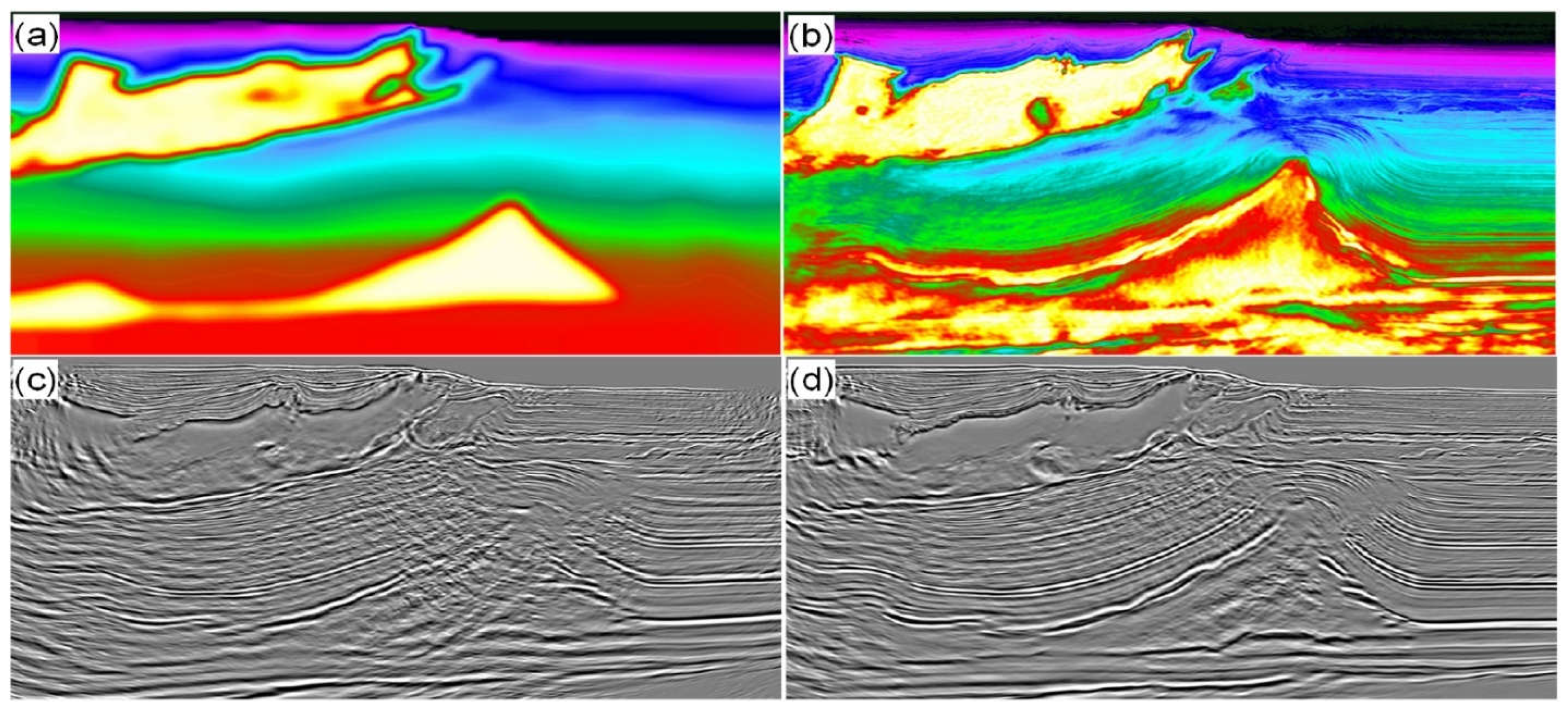
An interesting example of the integration between RTM and FWI is provided by Zhang et al. [29] using seismic data acquired above salt domes in the Atlantis field in the Gulf of Mexico. Their study shows that an improved velocity model provided by the FWI can greatly enhance the quality of the RTM images (see Figure 4a–d). The FWI modified the salt geometry imaged by seismic tomography (compare Figure 4a,b), which results in substantial enhancements in the RTM image, such as a considerable uplift of the salt (as shown in Figure 4d).

3.5. Seismic Anisotropy

In geology, the term anisotropy refers to the directional dependence of rock physical properties. Anisotropy can be caused by many factors, such as mineral alignment, fracture orientation and fluid-filled cracks. Seismic anisotropy [64,65,66] studies the variation of seismic wave velocity along different directions of propagation caused by anisotropy. Seismic anisotropy has important applications in structural geology. For example, in regions of tectonic deformation, seismic anisotropy can reveal the orientation and intensity of faulting and folding [67]. In sedimentary basins, seismic anisotropy can be used to image the orientation and distribution of minerals in sedimentary layers, and it has the potential to be used as an indicator of rock lithology [68].
Many studies of seismic anisotropy are based on the phenomenon of shear-wave splitting: when a shear wave travels through an anisotropic medium, it splits into two orthogonal polarization modes, which are known as the fast shear wave and slow shear wave [69,70,71,72,72,73,74]. An example of application can be found in Li et al. [75], who modeled the splitting of the shear-wave observed in crystalline rock bordering an active, normal fault-zone at Oroville, California, to quantitatively interpret P-wave polarization anomalies observed in the three-component seismograms recorded in the Oroville fault zone.
Azimuthal velocity measures seismic velocity variation with respect to the direction of propagation. Alford [76] introduced an efficient and effective way to separate the fast and slow shear modes in the sedimentary crust, which is now called Alford rotation. By using the rotation method, it was possible to detect the existence of azimuthal anisotropy in the upper crust, which is caused by deformation in the Earth’s crust and upper mantle [77,78,79].
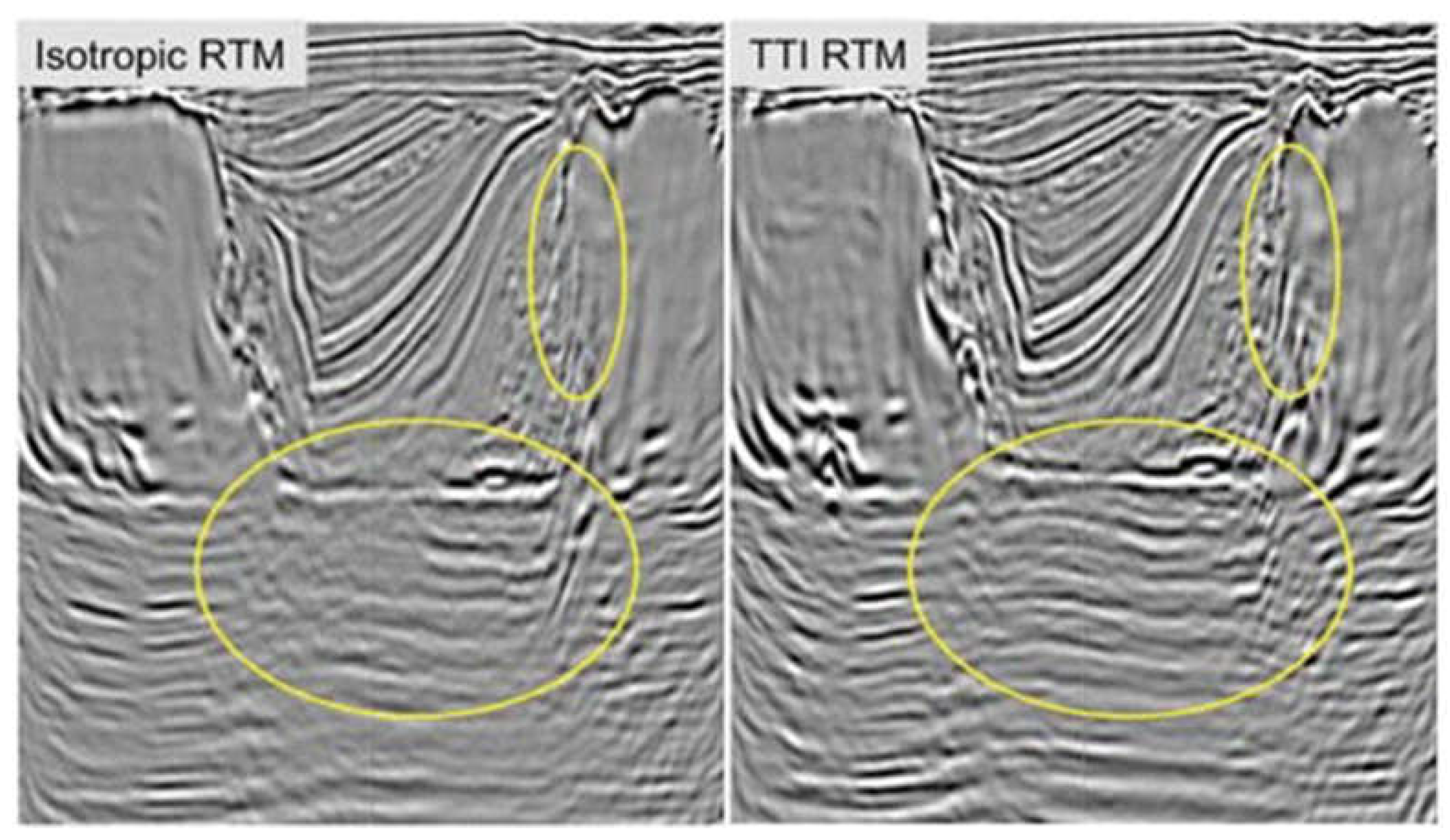
The dependence of anisotropy on many factors has limited its applications in seismic exploration. However, over the past two decades, technological advances in parameter estimation, PSDM, 3D survey coverage, and the acquisition of high-quality multicomponent data have significantly increased the role of anisotropy in seismic exploration, and many seismic processing and inversion methods now operate with anisotropic models [80]. Since the mid-1990s, high-quality multicomponent offshore surveys have shown that PP- and PS-wave sections cannot be tied in depth without considering anisotropy in the velocity model [80]. Although anisotropy-induced distortions in P-wave imaging are less dramatic, the progress in P-wave processing has largely been due to breakthroughs in the parameterization of transversely isotropic models [81,82]. Recently, PSDM has exposed the inadequacy of isotropic velocity models, with transversely isotropic models with a vertical and tilted axis of symmetry becoming standard in PSDM imaging projects worldwide [80]. Anisotropic algorithms have been particularly effective in producing improved images of subsalt exploration targets in the Gulf of Mexico (Figure 5: see Huang et al. [83]), which was a region that was previously considered to have a relatively mild anisotropy.

4. Seismic Attributes

Seismic attributes are mathematical representations of seismic data that provide additional information about the subsurface beyond what can be seen on a seismic image [84,85,86]. They are derived from seismic amplitude data through various mathematical operations and can be used to enhance the seismic image, highlight subtle features, and assist in the interpretation of geological structures [86]. Seismic attributes have developed with the aim to assist the interpretation in the exploration and production of hydrocarbons and other natural resources as well as in geohazard assessments and geothermal energy exploration [87]. This topic has been extensively researched and developed in the last few decades, and there are numerous types of seismic attributes that can be used to extract different types of geological information [87]. Seismic attributes have become increasingly important in the interpretation of faults and fractures [88,89,90]. Some of the main seismic attributes used for fault and fracture identification are briefly discussed below.

4.1. Reflection Strength Attributes

These attributes measure the strength of the seismic signal [86]. The trace envelope and energy attribute are the most used. The trace envelope is computed by taking the modulus of the complex seismic trace; the envelope represents the instantaneous energy of the signal and is proportional in its magnitude to the reflection coefficient. The energy attribute is instead a measure of reflectivity in a specified time window. Overall, both the trace envelope and energy attribute highlight areas of high/low reflectivity and can be used to detect discontinuities, lithological and depositional changes, tuning effect, and sequence boundaries [87]. However, to reduce the interpretation risk, these attributes should be used in combination with other attributes and data. An example of attribute integration can be seen in the work of Bruno et al. [91], who utilized a combination of the energy, coherence, and dip attributes to detect faults in the Centennial Valley, MT, USA. Their findings reveal that subvertical faults tend to occur in areas where lateral discontinuities in the energy match with low values of coherence and high values of the dip attribute (Figure 6).

4.2. Instantaneous Frequency

The instantaneous frequency is a seismic attribute that measures the time rate of change of the instantaneous phase of a seismic trace [92,93,94]. Instantaneous frequency is widely used for identifying specific seismic events, such as abnormal attenuation and thin bed tuning [87] based on its frequency content. It is one of the important seismic attributes related to the complex seismic trace. Although the definition itself is clear in theory, in practice, the calculation can vary considerably and deviate from the theoretical aim [95]. The instantaneous frequency is influenced by both wave propagation effects and depositional characteristics. This makes it a useful discriminator with a range of applications by identifying frequency anomalies [96]. For example, an unconsolidated sand can be recognized as a low-frequency anomaly, and this effect can be amplified by oil/gas saturation. Instantaneous frequency can also serve as an indicator of fracture zones, as fractures may also show up as lower-frequency zones especially if they are filled by fluids. Additionally, frequency can reveal bed thickness, with higher frequencies indicating sharp interfaces such as those found in thinly laminated shales, while lower frequencies are indicative of more massive bedding.

4.3. Coherence

Coherence [97,98,99,100] is a seismic attribute that measures the similarity of seismic waveforms at different locations. Coherence is basically a normalized cross-correlation computed between adjacent traces in the same survey. By normalizing the data, the amplitude and phase variability of source wavelet is eliminated, and waveform continuity can be quantified [87]. This attribute is used to highlight continuous and consistent reflectors; while its inverse indicates a poor correlation between the waveforms, thus suggesting a change in the reflectivity characteristics often caused by faults or other discontinuous geological characteristics in the seismic volume. For instance, coherence clearly reveals, without interpretation bias, features that are difficult to see in conventional seismic data, such as faults as well as buried deltas, river channels, reefs, and dewatering features [90,101].
The implementation of coherence in 3D seismic data, known as the “coherence cube”, caused a significant impact on the industry [87]. According to Bahorich and Farmer [98], their coherence methodology represented the pioneering approach for exposing fault surfaces within a 3D volume where no fault reflections had been previously detected.

4.4. Curvature

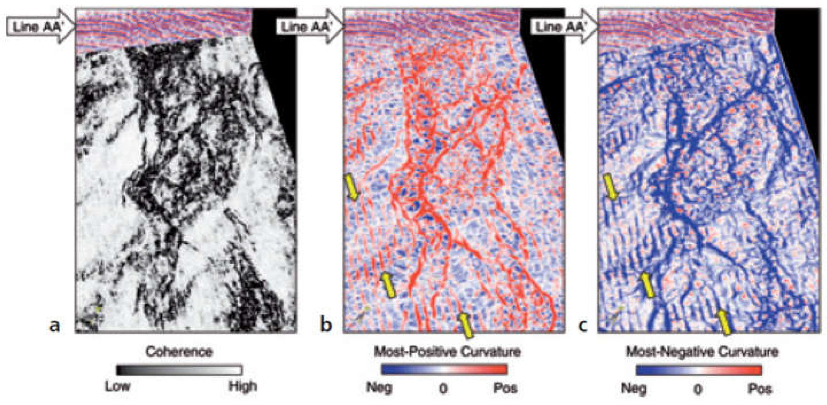
The curvature attribute is a horizon-based seismic attribute that measures the curvature of the seismic reflection events. As the previous statement suggests, curvature is calculated directly from a selected seismic horizon, and typically, it requires good data quality and the presence of a prominent impedance contrast in the horizon of interest [89]. Curvature obtained from horizons picked on noisy data can indeed lead to misleading results. The concept of curvature involves assessing the degree of bending of a surface at a particular point using volumetric techniques [102]. After picking and filtering a horizon on a seismic volume, a mathematical quadratic surface is fitted to the picks within a user-defined aperture. Subsequently, various measures of curvature are analytically computed based on the coefficients of the quadratic surface. Therefore, instead of analyzing variations in seismic amplitude, this attribute focuses on the geometric distortion. Roberts [102] presented the application of various curvature attributes. Among them, according to Chopra and Marfurt [89], the most-positive and most-negative curvature measures seem the most straightforward in establishing direct connections with geologic structural and stratigraphic features commonly encountered in the field, providing helpful information to coherence and other attributes (Figure 7 see also Mai et al. [103] and references therein).
To conclude, this attribute can effectively identify small-scale faults and fractures that may not be detectable with other attributes (e.g., Sigismondi and Soldo, [104]). For instance, Lisle [105] successfully correlated fractures measured on an outcrop to curvature values.

4.5. Polarization

Polarization provides an estimation of the orientation of the particle motion of a seismic wave when multicomponent data (i.e., recording of the seismic wavefield along two or three orthogonal directions) are available. Polarization analysis is therefore an important tool in seismic exploration. Techniques for analyzing the polarization of two- and three-component seismic data have been proposed by various authors [106,107,108,109,110,111,112,113]. However, processing multicomponent data poses more challenges than single-component data.; the challenge often arises in separating seismic events that exhibit distinct polarization characteristics [114]. Moreover, the interpretation of multicomponent data is difficult, which is mainly due to the lack of visualization techniques. Polarization attributes can address these difficulties allowing plotting multicomponent data with conventional seismic plotting techniques and therefore allowing an analysis of the polarization properties of multicomponent data in a more efficient and accurate manner (e.g., Morozov and Smithson, [115]).

4.6. Amplitude versus Offset Analysis

Amplitude versus offset (or AVO) measures the change in seismic wave amplitude with respect to the angle of incidence (or offset) of a source–receiver pair. AVO analysis can provide insights into the physical characteristics of the subsurface, such as lithology and fluid content. It is performed on individual traces on pre-stack seismic data and typically on common midpoint gathers [116]. One of the main advantages of the AVO is its ability to differentiate between different types of fluids (oil, gas, water) and lithology [117]. The AVO response of water-bearing formations, for example, is typically different from that of gas and oil-bearing formations, which makes AVO analysis useful in determining the presence of hydrocarbons. The theoretical basis of AVO was first developed by Knott [118] and Zoeppritz [119], which derived the equations for plane-wave reflection amplitudes as a function of incident angle, given the P-wave and S-wave velocities and densities of the two media. Koefoed [120] used the Zoeppritz equations to investigate the relationship between AVO and Poisson’s ratio and laid the foundation for modern AVO interpretation. Inspired by Koefoed’s work, Ostrander [121], Shuey [122], Rutherford and Williams [117], among others, made groundbreaking contributions to predicting lithology from AVO. In particular, Rutherford and Williams [115] introduced the industry standard classification of reflection coefficient curves which includes the classification of bright spot, phase reversal, and dim out. This classification was developed specifically for hydrocarbon saturated formations.
Several studies have demonstrated that the AVO analysis can be a very effective tool for fault and fracture characterization. For instance, Gray [123] shows that the use of seismic azimuthal AVO can effectively estimate fracture density and strike, as they are consistent with known fracture indicators from various sources such as core, outcrop, production, well logs, and structural interpretations. The good correlation between seismic azimuthal AVO and fracture indicators achieved by Gray [123] suggests that azimuthal AVO can provide valuable information about cross-well fracture information where other methods may not be feasible.
Reine and Lovric [124] used AVO inversion and fault intensity analysis to monitor hydraulic fracturing in shale-gas reservoirs together with microseismic and production data. They located faults on seismic reflection images and calculated the reservoir’s mechanical properties through an AVO inversion. Their study shows that hydraulic fractures tend to occur in areas with high fault intensity, which are followed by areas with high brittleness. The presence of natural faults affects the spatial distribution of the microseismic cloud and the velocity of fluid front propagation, resulting in events that move further and faster away from the well. Additionally, the results suggest that microseismic events reactivate existing fault planes and have magnitude distributions that resemble natural seismicity.

4.7. Seismic Attributes and Strain

Strain is a measure of the deformation experienced by a rock formation in response to an external stress state. Strain is a fundamental property of rocks since it is related to their mechanical properties. The strain can be estimated from seismic data using various attributes, such as AVO, coherence and curvature analysis. These methods provide information on the changes in the shape and orientation of seismic wavefronts as they propagate through the subsurface, which can be used to infer the amount and type of strain present [125].

5. Active Fault Characterization

Seismic exploration provides key data to understand subsurface structures and processes associated with faulting. The ability to image with high resolution the earth’s subsurface using seismic techniques has significantly contributed to a better understanding of the mechanism of surface rupture of seismogenic faults and holds a great potential to improve hazard assessment [16,31,126,127,128,129]. In recent years, the application of high-resolution seismic profiling has emerged as a powerful tool for studying the surface characteristics of active faults.
The identification and the study of seismogenic faults at the surface is crucial for seismic hazard assessment. Seismic exploration allows us to investigate fault geometries, fault slip rates, fault segmentation, and associated geological features [17,128,130,131]. Moreover, by analyzing the seismic data in conjunction with other geophysical and geological data sets, we can unravel the geometric and physical attributes of active fault zones, thereby yielding advantageous implications for the assessment of surface faulting hazards and comprehending the intricate interplay between faults and subsurface fluid dynamics (e.g., Maraio et al. [17]). The case studies presented below aim to highlight the significance of seismic exploration methods in studying the near-surface features of seismogenic faults.
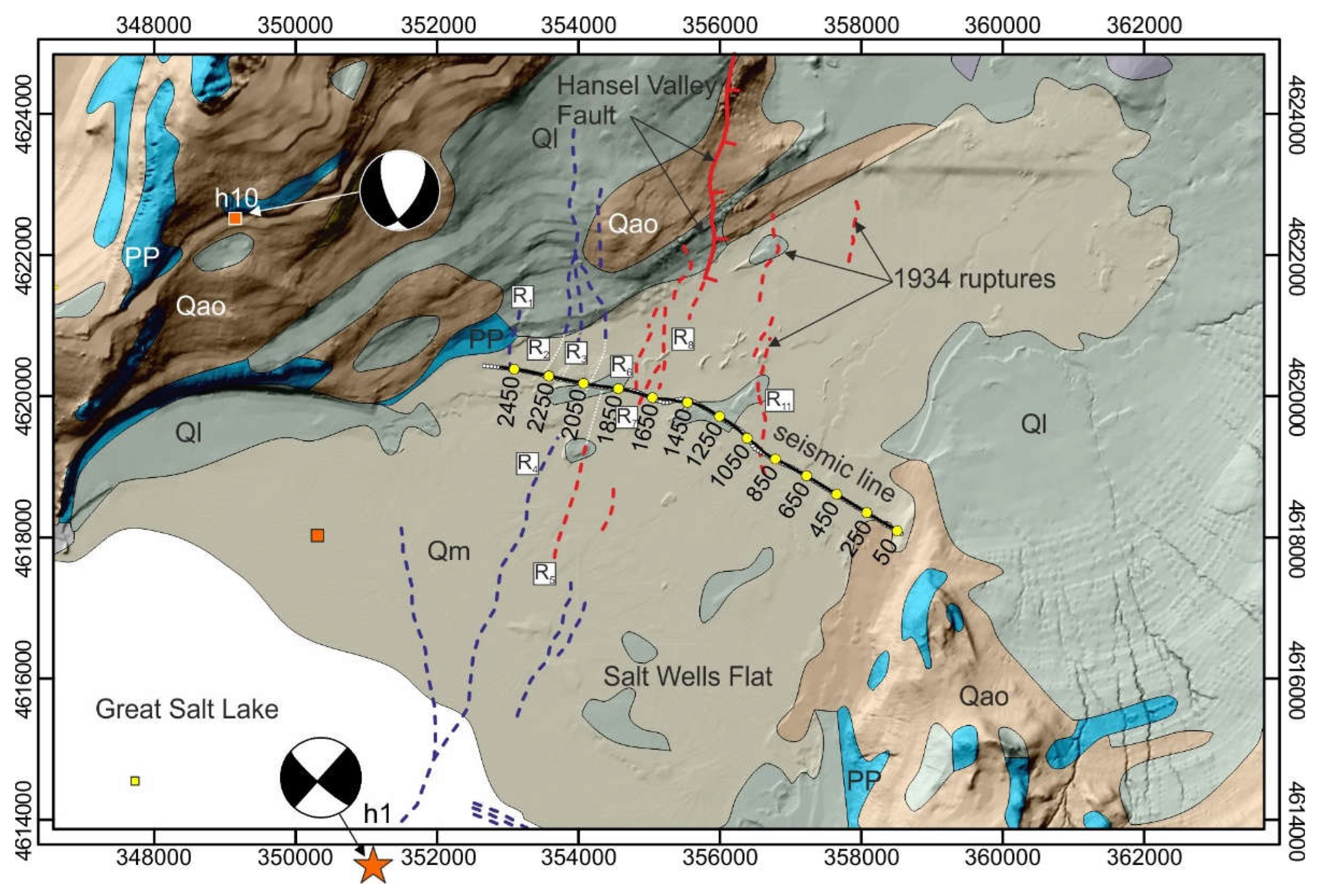
The first example is from Bruno et al. [131], who utilized high-resolution seismic profiling to investigate the faulting associated with the 1934 Ms 6.6 Hansel Valley earthquake in Utah, USA. Hansel Valley, situated north of the Great Salt Lake, is a fault-controlled extensional basin within the northeastern basin and range province [132,133,134,135]. The earthquake, which occurred on 12 March 1934, resulted in surface rupture in the southernmost part of Hansel Valley (Figure 8: Bruno et al. [131]) and is recognized as Utah’s only historic surface-faulting earthquake and one of the largest within the eastern basin and range province and Intermountain Seismic Belt [134]. The earthquake produced an 8 km-long by 3 km-wide zone of north–south trending surface deformation. Despite surface measurements indicating less than 0.5 m of vertical displacement, seismological data suggested mostly strike–slip faulting at depth.
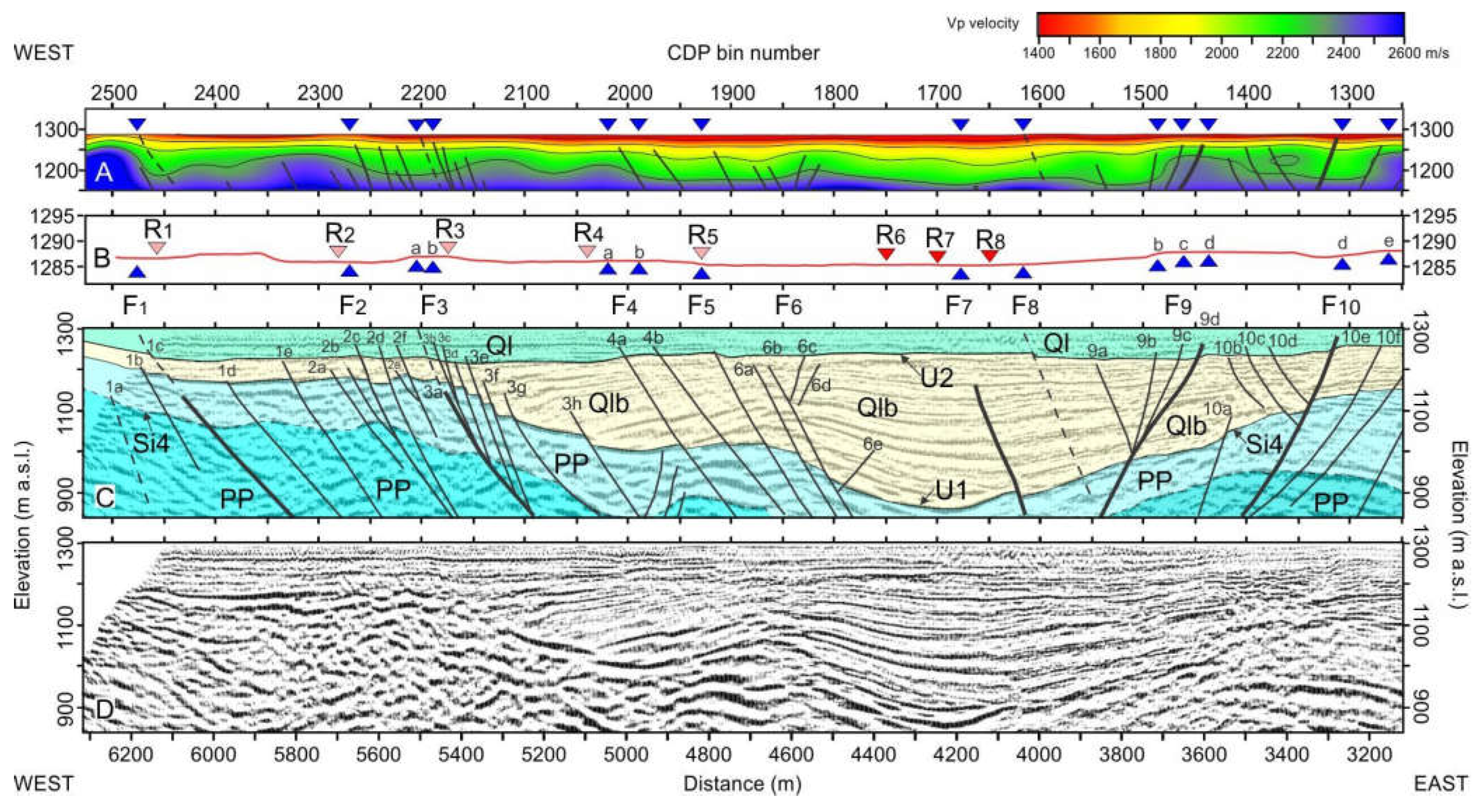
The study of Bruno et al. [131] aimed to assess the origin of the ruptures occurred during the 1934 Hansel Valley earthquake to gain insights into the way complex fault ruptures accommodate regions of continental extension and transtension. By employing a 6.6 km-long, high-resolution seismic survey, Bruno et al. [131] found that the 1934 surface ruptures were not secondary in nature but represented the direct expression of coseismic deformation along numerous shallow faults beneath the valley floor. The seismic data indicate a complex tectonic framework for Hansel Valley, characterized by diffuse faulting and a broad negative flower structure that extends to depths of at least 1 km. Their results suggested that normal–oblique slip faulting is active in Hansel Valley, which is consistent with geological observations made shortly after the earthquake and focal mechanisms [134] implying primarily left–lateral, strike–slip faulting at a seismogenic depth of approximately 8.5 km.
Bruno et al. [131] explained the apparent discrepancy between shallow and deep fault kinematics through slip partitioning during fault propagation. The researchers proposed that the causative rupture of the 1934 Hansel Valley earthquake occurred most probably along an immature fault zone, where surface deformation was redistributed within a ~3 km wide off-fault damage zone. The damage zone is characterized by numerous small-offset, shallow normal-fault strands (Figure 9) that may have been alternately and differentially activated during multiple earthquake episodes at seismogenic depths. The findings of the study demonstrated the usefulness of using dense, wide-aperture seismic reflection profiling for the high-resolution exploration of a basin–range fault system that exhibits minor surficial expressions and/or has long recurrence intervals.
Kaiser et al. [16] provide another fascinating application of high-resolution seismic imaging on active faults. Their research focused on the Alpine Fault system located on New Zealand’s South Island (see Sutherland et al. [137] and references therein). By utilizing high-resolution seismic reflection and ground-penetrating radar (GPR) data across the Alpine Fault, the authors aimed to enhance their understanding of this active fault beyond the limitations of conventional paleoseismological methods [13,14].
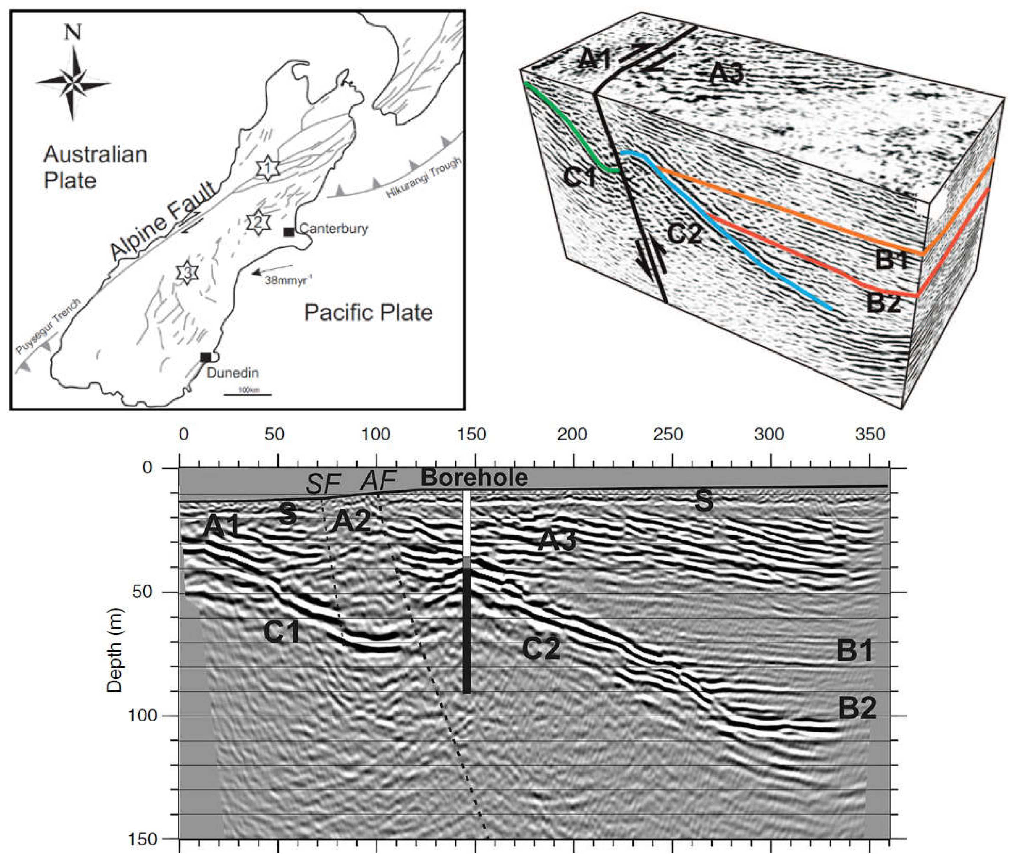
New Zealand’s South Island accommodates two active subduction zones: the west-striking Hikurangi subduction zone in the north is connected to the east-striking Puysegur subduction zone in the south through the Alpine Fault zone and a broad zone of oblique compression (Figure 10). Historical and instrumental records of seismicity do not fully capture the earthquake cycle of these fault zones due to the relatively short duration of available records (~200 years and ~50 years for historical and instrumental seismicity, respectively) compared to the estimated recurrence intervals of the active faults, which span several hundred years [138]. Therefore, paleoseismic studies play a crucial role in characterizing the numerous active faults that extend across the country (see Sutherland et al. [137] and references therein). These studies indicate that the Alpine Fault, in the central and southern parts of the South Island, accounts for two-thirds to three-quarters of the 35–38 mm/y of relative motion between the Australian and Pacific plates. The remaining motion is distributed over a 150–200 km-wide region encompassing the Southern Alps and adjacent areas to the east (Figure 10; see Norris et al. [139] and references therein).
To extend the capabilities of conventional paleoseismological methods, Kaiser et al. [16] employed an ultra-high-resolution 2D seismic reflection data set and a pseudo-3D seismic reflection data set across the Alpine Fault zone (Figure 10). Their pseudo-3D survey involved detonating explosive charges, which were simultaneously recorded by receivers positioned along two parallel lines. This acquisition strategy ensured a uniform and dense distribution of seismic traces with offset and allowed us to simplify critical processing steps, although it had limitations on the azimuthal range of source–receiver raypaths. According to Kaiser et al. [16], this cost-effective acquisition strategy may be an alternative to full 3D surveying methods in those fault zones where variations in structure along the fault strike are expected to be less pronounced than in the orthogonal direction. Preliminary interpretations from their study suggest that the primary strand within the shallow Alpine Fault zone exhibits a steep dip and relatively planar characteristics in the late Quaternary sediments and basement down to a depth of at least 150 m. The authors also show that the joint interpretation of 2D and pseudo-3D seismic images, with GPR data, provides further insights into the distribution of subtle deformation structures within the shallow sediments.
The two examples above show that seismic methods can deliver additional information useful to enhance our understanding of near-surface active faults. However, when dealing with complex fault structures or weak surface expressions, the real breakthrough lies in the integration of multi-parametric data. A case of complex structure is represented by the Irpinia Fault, the source of the 4th largest Italian earthquake of the last century (1980, Ms 6.9, Irpinia earthquake; [140,141], which was recognized solely after the 1980 earthquake through coseismic scarps and the timing of paleo-events observed on different sectors of the fault by Pantosti et al. [141]. Their findings suggest that the Irpinia Fault represents a major seismogenic source in the southern Apennines, which is a region of Italy known for its potential to generate up to M7 earthquakes and is therefore included among the areas with the highest seismogenic potential in the Mediterranean region.
Recently, Bruno et al. [142] conducted a multidisciplinary geophysical study on an active fault strand of the Irpinia Fault in an intramontane basin of the southern Apennines. Their aim was to achieve an accurate 3D geophysical imaging of the shallow structure of the fault zone by integrating a conspicuous multivariate dataset. The test site had previously been the focus of several high-resolution 2D seismic surveys by Bruno et al. [131], who highlighted the three-dimensional nature of the fault strand and emphasized the fact that in the southern Apennines, often, the classical analysis of short-term morpho-tectonic indicators observed at the surface alone is insufficient for active fault detection and characterization. Bruno et al. [142] complemented the geophysical survey initiated in 2010 with a comprehensive dataset composed of a microgravimetric survey, 3D and 2D electrical resistivity measurements, 3D and 2D seismic reflection data, aeromagnetic and GPR surveys conducted by drone, and a detailed sampling of CO2 surface degassing across the fault surface rupture. In general, the integration of multivariate datasets has the potential to greatly reduce the interpretation risk and increase our understanding of the mechanism of active faulting in the near surface. Moreover, multivariate datasets could pave the way for the development of new imaging techniques that could significantly improve our imaging capabilities of complex faut zones.

6. Conclusions

Seismic imaging is a fundamental tool for probing the earth’s subsurface and characterizing fault zones. Seismic imaging has been extensively used in the exploration for energy resources since its development, occurred in the 1920s, and over the years, it has undergone continuous improvements in data acquisition, processing, and interpretation. These improvements have led to significant advances in accuracy, resolution, and computational efficiency.
For example, the dense, wide-aperture field technique allows the use of several imaging procedures on the same dataset, resulting in an improved estimation of seismic velocities and in a better subsurface imaging. Seismic ray tomography and full waveform inversion are powerful techniques that integrate the seismic reflection data processing. However, the accuracy of the results can be influenced by the complexity of the subsurface geology. Full-waveform inversion provides high-resolution images of the subsurface and detailed information on geological formations, even though building an accurate initial model for FWI remains a pressing concern.
Pre-stack depth migration, which is often used in conjunction with refraction tomography and/or with full-waveform inversion, overcomes the limitations of conventional common midpoint stacking, which relies on the hyperbolic traveltime assumption, for pre-stack reflected events, allowing a proper computation of amplitudes and traveltimes associated with non-hyperbolic reflection events originated by complex subsurface settings. Seismic attributes, seismic anisotropy and AVO have become increasingly important in improving seismic imaging and in aiding the interpretation. A few examples from recent studies focus on the use of seismic exploration methods to study active faults. Through these examples, it is shown the valuable contribution of seismic exploration in this field.
By routinely integrating seismic data with other geophysical and geological information, we can pave the way for a more accurate imaging interpretation of the subsurface and for better seismic hazard assessments in earthquake-prone regions. In this context, the use of machine learning techniques has also shown promise in improving the consistency of seismic data processing and interpretation.

Funding

This research received no external funding.

Institutional Review Board Statement

Not applicable.

Informed Consent Statement

Not applicable.

Data Availability Statement

No new data were created in this review paper.

Conflicts of Interest

The author declares no conflict of interest.

References

  1. O’Brien, P.N.S. Aspects of seismic reflection prospecting for oil and gas. Geophys. J. Int. 1983, 74, 97–127. [Google Scholar] [CrossRef]
  2. Sheriff, R.; Geldart, L. Exploration Seismology; Cambridge University Press: Cambridge, UK, 1995. [Google Scholar]
  3. Wadsworth, G.P.; Robinson, E.A.; Bryan, J.G.; Hurley, P.M. Detection of reflection on seismic records by linear operators. Geophysics 1953, 18, 539–586. [Google Scholar] [CrossRef]
  4. Robinson, E.A.; Clark, R.D. Reflecting on the digital revolution. Lead. Edge 2005, 24, 1030–1032. [Google Scholar] [CrossRef]
  5. Robinson, E.A. The MIT Geophysical Analysis Group (GAG) from inception to 1954. Geophysics 2005, 70, 7JA–30JA. [Google Scholar] [CrossRef]
  6. Treitel, S. The MIT geophysical analysis group (GAG): 1954 and beyond. Geophysics 2005, 70, 31JA–35JA. [Google Scholar] [CrossRef]
  7. Steeples, D.W.; Schmeissner, C.M.; Macy, B.K. The Evolution of Shallow Seismic Exploration. J. Environ. Eng. Geophys. 1995, 1, 1–66. [Google Scholar] [CrossRef]
  8. Steeples Don, W. A review of shallow seismic methods. Ann. Geofis. 2000, 43, 1021–1044. [Google Scholar] [CrossRef]
  9. Tucker, P.M.; Yorston, H.J. Pitfalls in Seismic Interpretation; No. 2; SEG: Tulsa, OK, USA, 1973. [Google Scholar]
  10. Badley, M.E. Practical Seismic Interpretation; IHRDC Press: Boston, MA, USA, 1985. [Google Scholar]
  11. Avseth, P.; Mukerji, T.; Mavko, G. Quantitative Seismic Interpretation: Applying Rock Physics Tools to Reduce Interpretation Risk; Cambridge University Press: Cambridge, UK, 2010. [Google Scholar]
  12. Khan, U.; Zhang, B.; Du, J.; Jiang, Z. 3D structural modeling integrated with seismic attribute and petrophysical evaluation for hydrocarbon prospecting at the Dhulian Oilfield, Pakistan. Front. Earth Sci. 2021, 15, 649–675. [Google Scholar] [CrossRef]
  13. McCalpin, J.P. Paleoseismology; Academic Press: San Diego, CA, USA, 1996. [Google Scholar]
  14. Yeats, R.S.; Sieh, K.E.; Allen, C.R. Geology of Earthquakes; Oxford University Press: Oxford, UK, 1996. [Google Scholar]
  15. Thenhaus, P.C.; Campbell, K.W. Seismic hazard analysis: In Earthquake Engineering Handbook; Chen, W.F., Scawthorn, C., Eds.; CRC Press: Boca Raton, FL, USA, 2003; pp. 1–50. [Google Scholar]
  16. Kaiser, A.E.; Horstmeyer, H.; Green, A.G.; Campbell, F.M.; Langridge, R.M.; McClymont, A.F. Detailed images of the shallow Alpine Fault Zone, New Zealand, determined from narrow-azimuth 3D seismic reflection data. Geophysics 2011, 76, B19–B32. [Google Scholar] [CrossRef]
  17. Maraio, S.; Villani, F.; Bruno, P.P.G.; Sapia, V.; Improta, L. Active fault detection and characterization by ultrashallow seismic imaging: A case study from the 2016 Mw 6.5 central Italy earthquake. Tectonophysics 2023, 850, 229733. [Google Scholar] [CrossRef]
  18. Waters, K.H. Reflection Seismology: A Tool for Energy Resource Exploration; Wiley: New York, NY, USA, 1981; p. 537. [Google Scholar]
  19. Yilmaz, O. Seismic data analysis (2 volumes). In Investigations in Geophysics; SEG: Tulsa, OK, USA, 2001; Volume 10, p. 1000. [Google Scholar]
  20. Caldwell, J.; Dragoset, W. A brief overview of seismic air-gun arrays. Lead. Edge 2000, 8, 817–928. [Google Scholar] [CrossRef]
  21. Stone, C.J.; Tasker, M.L. The effects of seismic airguns on cetaceans in UK waters. J. Cetacean Res. Manag. 2006, 8, 255. [Google Scholar] [CrossRef]
  22. Neidell, N.S.; Taner, M.T. Semblance and other coherency measures for multichannel data. Geophysics 1971, 36, 482–497. [Google Scholar] [CrossRef]
  23. Claerbout, J.F. Imaging the Earth’s Interior; Blackwell Scientific Publications: Hoboken, NJ, USA, 1985. [Google Scholar]
  24. Lailly, P. The seismic inverse problem as a sequence of before stack migrations. In Conference on Inverse Scattering: Theory and Application; Society for Industrial and Applied Mathematics: Philadelphia, PA, USA, 1983; pp. 206–220. [Google Scholar]
  25. Tarantola, A. Inversion of seismic reflection data in the acoustic approximation. Geophysics 1984, 49, 1259–1266. [Google Scholar] [CrossRef]
  26. Virieux, J.; Operto, S. An overview of full-waveform inversion in exploration geophysics. Geophysics 2009, 74, WCC1–WCC26. [Google Scholar] [CrossRef]
  27. Biondi, B.; Almomin, A. Tomographic full waveform inversion (TFWI) by combining full waveform inversion with wave-equation migration velocity anaylisis. In SEG Technical Program Expanded Abstracts 2012; Society of Exploration Geophysicists: Houston, TX, USA, 2012; pp. 1–5. [Google Scholar]
  28. Richardson, A. Seismic full-waveform inversion using deep learning tools and techniques. arXiv 2018, arXiv:1801.07232. [Google Scholar]
  29. Zhang, Z.; Wu, Z.; Wei, Z.; Mei, J.; Huang, R.; Wang, P. FWI Imaging: Full-Wavefield Imaging through Full-Waveform Inversion: 90th Annual International Meeting, SEG Expanded Abstracts, 656–660. Abstract. 2020. Available online: https://library.seg.org/doi/abs/10.1190/segam2020-3427858.1 (accessed on 16 March 2023).
  30. Operto, S.; Ravaut, C.; Improta, L.; Virieux, J.; Herrero, A.; Dell’Aversana, P. Quantitative imaging of complex structures from dense wide-aperture seismic data by multiscale traveltime and waveform inversions: A case study. Geophys. Prospect. 2004, 52, 625–651. [Google Scholar] [CrossRef]
  31. Improta, L.; Bruno, P.P. Combining seismic reflection with multifold wide-aperture profiling: An effective strategy for high-resolution shallow imaging of active faults. Geophys. Res. Lett. 2007, 34. [Google Scholar] [CrossRef]
  32. Bruno, P.P.; Castiello, A.; Villani, F.; Improta, L. High-resolution densely spaced wide-aperture seismic profiling as a tool to aid seismic hazard assessment of fault-bounded intramontane basins: Application to Vallo Di Diano, Southern Italy. Bull. Seismol. Soc. Am. 2013, 103, 1969–1980. [Google Scholar] [CrossRef]
  33. Ravaut, C.; Operto, S.; Improta, L.; Virieux, J.; Herrero, A.; Dell’Aversana, P. Multiscale imaging of complex structures from multifold wide-aperture seismic data by frequency-domain full-waveform tomography: Application to a thrust belt. Geophys. J. Int. 2004, 159, 1032–1056. [Google Scholar] [CrossRef]
  34. Wei, X.; Ruan, A.; Ding, W.; Wu, Z.; Dong, C.; Zhao, Y.; Niu, X.; Zhang, J.; Wang, C. Crustal structure and variation in the southwest continental margin of the South China Sea: Evidence from a wide-angle seismic profile. J. Asian Earth Sci. 2020, 203, 104557. [Google Scholar] [CrossRef]
  35. Nolet, G. Seismic Tomography: With Applications in Global Seismology and Exploration Geophysics; Springer Science and Business Media: Berlin/Heidelberg, Germany, 1987. [Google Scholar]
  36. Rawlinson, N.; Sambridge, M. Seismic traveltime tomography of the crust and lithosphere. Adv. Geophys. 2005, 46, 81–139. [Google Scholar]
  37. Zelt, C.A.; Barton, P.J. Three-dimensional seismic refraction tomography: A comparison of two methods applied to data from the Faeroe Basin. J. Geophys. Res. Solid Earth 1998, 103, 7187–7210. [Google Scholar] [CrossRef]
  38. Tarantola, A.; Valette, B. Generalized nonlinear inverse problems solved using the least squares criterion. Rev. Geophys. 1982, 20, 219–232. [Google Scholar] [CrossRef]
  39. Rawlinson, N.; Pozgay, S.; Fishwick, S. Seismic tomography: A window into deep Earth. Phys. Earth Planet. Inter. 2010, 178, 101–135. [Google Scholar] [CrossRef]
  40. Buddensiek, M.L.; Sheng, J.; Crosby, T.; Schuster, G.T.; Bruhn, R.L.; He, R. Colluvial wedge imaging using traveltime and waveform tomography along the Wasatch Fault near Mapleton, Utah. Geophys. J. Int. 2008, 172, 686–697. [Google Scholar] [CrossRef]
  41. Improta, L.; Villani, F.; Bruno, P.P.; Castiello, A.; De Rosa, D.; Varriale, F.; Punzo, M.; Brunori, C.A.; Civico, R.; Pierdominici, S.; et al. High-resolution controlled-source seismic tomography across the Middle Aterno basin in the epicentral area of the 2009, Mw 6.3, L’Aquila earthquake (central Apennines, Italy). Ital. J. Geosci. 2012, 131, 373–388. [Google Scholar]
  42. Villani, F.; Improta, L.; Pucci, S.; Civico, R.; Bruno, P.P.G.; Pantosti, D. Investigating the architecture of the Paganica Fault (2009 Mw 6.1 earthquake, central Italy) by integrating high-resolution multi-scale refraction tomography and detailed geological mapping. Geophys. J. Int. 2016, 208, ggw407. [Google Scholar]
  43. Bruno, P.P.G.; Villani, F.; Improta, L. High-Resolution Seismic Imaging of Fault-Controlled Basins: A Case Study From the 2009 Mw 6.1 Central Italy Earthquake. Tectonics 2022, 41, e2022TC007207. [Google Scholar] [CrossRef]
  44. Wang, P.; Zhang, Z.; Mei, J.; Lin, F.; Huang, R. Full-waveform inversion for salt: A coming of age. Lead. Edge 2019, 38, 204–213. [Google Scholar] [CrossRef]
  45. Brossier, R.; Operto, S.; Virieux, J. Seismic imaging of complex onshore structures by 2D elastic frequency-domain full-waveform inversion. Geophysics 2009, 74, WCC105–WCC118. [Google Scholar] [CrossRef]
  46. Woodward, M.J.; Nichols, D.; Zdraveva, O.; Whitfield, P.; Johns, T. A decade of tomography. Geophysics 2008, 73, VE5–VE11. [Google Scholar] [CrossRef]
  47. Vantassel, J.P.; Kumar, K.; Cox, B.R. Using convolutional neural networks to develop starting models for near-surface 2-D full waveform inversion. Geophys. J. Int. 2022, 231, 72–90. [Google Scholar] [CrossRef]
  48. Zhang, Z.; Alkhalifah, T. Regularized elastic full-waveform inversion using deep learning. In Advances in Subsurface Data Analytics; Elsevier: Amsterdam, The Netherlands, 2022; pp. 219–250. [Google Scholar]
  49. Dessa, J.X.; Operto, S.; Kodaira, S.; Nakanishi, A.; Pascal, G.; Virieux, J.; Kaneda, Y. Multiscale seismic imaging of the eastern Nankai trough by full waveform inversion. Geophys. Res. Lett. 2004, 31. [Google Scholar] [CrossRef]
  50. Shen, X.; Ahmed, I.; Brenders, A.; Dellinger, J.; Etgen, J.; Michell, S. Full-waveform inversion: The next leap forward in subsalt imaging. Lead. Edge 2018, 37, b1–b67. [Google Scholar] [CrossRef]
  51. Adamczyk, A.; Malinowski, M.; Malehmir, A. High-resolution near-surface velocity model building using full-waveform inversion—A case study from southwest Sweden. Geophys. J. Int. 2014, 197, 1693–1704. [Google Scholar] [CrossRef]
  52. Schneider, W. Integral formulation for migration in two and three dimensions. Geophysics 1978, 43, 49–76. [Google Scholar] [CrossRef]
  53. Hagedoorn, J. A process of seismic reflection interpretation. Geophys. Prospect. 1954, 2, 85–127. [Google Scholar] [CrossRef]
  54. Claerbout, J.F.; Doherty, S.M. Downward continuation of moveout-corrected seismo-grams. Geophysics 1972, 37, 741–768. [Google Scholar] [CrossRef]
  55. Gazdag, J. Wave-equation migration by phase shift. Geophysics 1978, 43, 1342–1351. [Google Scholar] [CrossRef]
  56. Stolt, R.H. Migration by Fourier transform. Geophysics 1978, 43, 23–48. [Google Scholar] [CrossRef]
  57. Stolt, R.H.; Benson, A.K. Seismic Migration: Theory and Practice; Geophysical Press: Amsterdam, The Netherlands, 1986. [Google Scholar]
  58. Sen, M.K.; Stoffa, P.L. Global Optimization Methods in Geophysical Inversion; Cambridge University Press: Cambridge, UK, 2013. [Google Scholar]
  59. McMechan, G.A. Migration by extrapolation of time-dependent boundary values. Geophys. Prospect. 1983, 31, 413–420. [Google Scholar] [CrossRef]
  60. Baysal, E.; Kosloff, D.D.; Sherwood, J.W. Reverse time migration. Geophysics 1983, 48, 1514–1524. [Google Scholar] [CrossRef]
  61. Whitmore, N.D.; Lines, L.R. Vertical seismic profiling depth migration of a salt dome flank. Geophysics 1986, 51, 1087–1109. [Google Scholar] [CrossRef]
  62. Mora, P. Inversion = migration + tomography. Geophysics 1989, 54, 1575–1586. [Google Scholar] [CrossRef]
  63. Chattopadhyay, S.; McMechan, G.A. Imaging conditions for prestack reverse-time migration. Geophysics 2008, 73, S81–S89. [Google Scholar] [CrossRef]
  64. Babuska, V.; Cara, M. Seismic Anisotropy in the Earth; Springer Science and Business Media: Berlin/Heidelberg, Germany, 1991; Volume 10. [Google Scholar]
  65. Savage, M.K. Seismic anisotropy and mantle deformation: What have we learned from shear wave splitting? Rev. Geophys. 1999, 37, 65–106. [Google Scholar] [CrossRef]
  66. Helbig, K.; Thomsen, L. 75-plus years of anisotropy in exploration and reservoir seismics: A historical review of concepts and methods. Geophysics 2005, 70, 9ND–23ND. [Google Scholar] [CrossRef]
  67. Liu, J.; Wu, J.; Wang, W.; Cai, Y.; Fang, L. Seismic anisotropy and implications for lithospheric deformation beneath the Ordos Block and surrounding regions. Geophys. J. Int. 2021, 226, 1885–1896. [Google Scholar] [CrossRef]
  68. Valcke, S.L.A.; Casey, M.; Lloyd, G.E.; Kendall, J.M.; Fisher, Q.J. Lattice preferred orientation and seismic anisotropy in sedimentary rocks. Geophys. J. Int. 2006, 166, 652–666. [Google Scholar] [CrossRef]
  69. Crampin, S. A review of wave motion in anisotropic and cracked elastic-media. Wave Motion 1981, 3, 343–391. [Google Scholar] [CrossRef]
  70. Crampin, S. Evaluation of anisotropy by shear-wave splitting. Geophysics 1985, 50, 142–152. [Google Scholar] [CrossRef]
  71. Crampin, S. The New Geophysics: Shear-wave splitting provides a window into the crack-critical rock mass. Lead. Edge 2003, 22, 536–549. [Google Scholar] [CrossRef]
  72. Lynn, H.B.; Thomsen, L. Shear wave exploration along the principal axis. In Proceedings of the 56th Annual International Meeting, SEG, Expanded Abstracts, Houston, TX, USA, 2–6 November 1986; pp. 474–476. [Google Scholar]
  73. Willis, H.; Rethford, G.; Bielanski, E. Azimuthal anisotropy: The occurence and effect on shear wave data quality. In Proceedings of the 56th Annual International Meeting, SEG, Expanded Abstracts, Houston, TX, USA, 2–6 November 1986; pp. 479–481. [Google Scholar]
  74. Martin, M.A.; Davis, T.L. Shear-wave birefringence: A new tool for evaluating fractured reservoirs. Lead. Edge 1987, 6, 22–28. [Google Scholar] [CrossRef]
  75. Li, Y.G.; Leary, P.C.; Aki, K. Observation and modelling of fault-zone fracture seismic anisotropy—II. P-wave polarization anomalies. Geophys. J. Int. 1987, 91, 485–492. [Google Scholar] [CrossRef]
  76. Alford, R.M. Shear data in the presence of azimuthal anisotropy. In Proceedings of the 56th Annual International Meeting, SEG, Expanded Abstracts, Houston, TX, USA, 2–6 November 1986; pp. 476–479. [Google Scholar]
  77. Montagner, J.P.; Guillot, L. Seismic anisotropy and global geodynamics. Rev. Mineral. Geochem. 2002, 51, 353–385. [Google Scholar] [CrossRef]
  78. Long, M.D.; Becker, T.W. Mantle dynamics and seismic anisotropy. Earth Planet. Sci. Lett. 2010, 297, 341–354. [Google Scholar] [CrossRef]
  79. Schaeffer, A.J.; Lebedev, S.; Becker, T.W. Azimuthal seismic anisotropy in the Earth’s upper mantle and the thickness of tectonic plates. Geophys. Suppl. Mon. Not. R. Astron. Soc. 2016, 207, 901–933. [Google Scholar] [CrossRef]
  80. Tsvankin, I.; Gaiser, J.; Grechka, V.; Van Der Baan, M.; Thomsen, L. Seismic anisotropy in exploration and reservoir characterization: An overview. Geophysics 2010, 75, A15–A75. [Google Scholar] [CrossRef]
  81. Thomsen, L. Weak elastic anisotropy. Geophysics 1986, 51, 1954–1966. [Google Scholar] [CrossRef]
  82. Alkhalifah, T.; Tsvankin, I. Velocity analysis for transversely isotropic media. Geophysics 1995, 60, 1550–1566. [Google Scholar] [CrossRef]
  83. Huang, T.; Zhang, Y.; Zhang, H.; Young, J. Subsalt imaging using TTI reverse time migration. Lead. Edge 2009, 28, 448–452. [Google Scholar] [CrossRef]
  84. Taner, M.T.; Sheriff, R.E. Application of Amplitude, Frequency, and Other Attributes to Stratigraphic and Hydrocarbon Determination; Society of Exploration Geophysicists: Houston, TX, USA, 1977. [Google Scholar]
  85. Craven, J.A.; Styles, P. Seismic curvature attributes for fault/fracture detection. Lead. Edge 1999, 18, 342–346. [Google Scholar]
  86. Chopra, S.; Marfurt, K. Seismic Attributes for Prospect Identification and Reservoir Characterization; SEG: Tulsa, OK, USA, 2007. [Google Scholar]
  87. Chopra, S.; Marfurt, K.J. Seismic attributes—A historical perspective. Geophysics 2005, 70, 3SO–28SO. [Google Scholar] [CrossRef]
  88. Chopra, S.; Marfurt, K.J. Volumetric curvature attributes for fault/fracture characterization. First Break 2007, 25. [Google Scholar] [CrossRef]
  89. Chopra, S.; Marfurt, K.J. Seismic attributes for fault/fracture characterization. In SEG International Exposition and Annual Meeting; SEG: Tulsa, OK, USA, 2007; p. SEG-2007. [Google Scholar]
  90. Castillo, F. Seismic Attributes for 3-D Fracture Interpretation; Halliburton: Calgary, AB, Canada, 2010. [Google Scholar]
  91. Bruno, P.P.G.; Berti, C.; Pazzaglia, F.J. Accommodation, slip inversion, and fault segmentation in a province-scale shear zone from high-resolution, densely spaced wide-aperture seismic profiling, Centennial Valley, MT, USA. Sci. Rep. 2019, 9, 9214. [Google Scholar] [CrossRef]
  92. Barnes, A.E. Instantaneous frequency and amplitude at the envelope peak of a constant-phase wavelet. Geophysics 1991, 56, 1058–1060. [Google Scholar] [CrossRef]
  93. Barnes, A.E. The calculation of instantaneous frequency and instantaneous bandwidth. Geophysics 1992, 57, 1520–1524. [Google Scholar] [CrossRef]
  94. Cohen, L. Time-Frequency Analysis; Prentice Hall: Hoboken, NJ, USA, 1995; Volume 778. [Google Scholar]
  95. Xing, L.; Aarre, V.; Barnes, A.; Theoharis, T.; Salman, N.; Tjåland, E. Instantaneous frequency seismic attribute benchmarking. In SEG Technical Program Expanded Abstracts 2017; Society of Exploration Geophysicists: Houston, TX, USA, 2017; pp. 2086–2090. [Google Scholar]
  96. Taner, M.T.; Rock Solid Images. Seismic Attributes: CSEG Recorder; Rock Solid Images: Houston, TX, USA, 2001. [Google Scholar]
  97. Bahorich, M.S.; Farmer, S.L. 3-D seismic discontinuity for faults and stratigraphic features: The coherence cube. Lead. Edge 1995, 14, 1053–1058. [Google Scholar] [CrossRef]
  98. Marfurt, K.J.; Kirlin, R.L.; Farmer, S.L.; Bahorich, M.S. 3-D seismic attributes using a semblance-based coherency algorithm. Geophysics 1998, 63, 1150–1165. [Google Scholar] [CrossRef]
  99. Marfurt, K.J.; Sudhaker, V.; Gersztenkorn, A.; Crawford, K.D.; Nissen, S.E. Coherency calculations in the presence of structural dip. Geophysics 1999, 64, 104–111. [Google Scholar] [CrossRef]
  100. Gersztenkorn, A.; Marfurt, K.J. Eigen structure-based coherence computations as an aid to 3-D structural and stratigraphic mapping. Geophysics 1999, 64, 1468–1479. [Google Scholar] [CrossRef]
  101. Li, F.; Lu, W. Coherence attribute at different spectral scales. Interpretation 2014, 2, SA99–SA106. [Google Scholar] [CrossRef]
  102. Roberts, A. Curvature attributes and their application to 3 D interpreted horizons. First Break 2001, 19, 85–100. [Google Scholar] [CrossRef]
  103. Mai, H.T.; Marfurt, K.J.; Chávez-Pérez, S. Coherence and volumetric curvatures and their spatial relationship to faults and folds, an example from Chicontepec basin, Mexico. In Proceedings of the 2009 SEG Annual Meeting, OnePetro, Houston, TX, USA, 25–30 October 2009. [Google Scholar]
  104. Sigismondi, E.M.; Soldo, C.J. Curvature attributes and seismic interpretation: Case studies from Argentina basins. Lead. Edge 2003, 22, 1122–1126. [Google Scholar] [CrossRef]
  105. Lisle, R.J. Detection of zones of abnormal strains in structures using Gaussian curvature analysis. AAPG Bull. 1994, 78, 1811–1819. [Google Scholar]
  106. Plesinger, A.; Hellweg, M.; Seidl, D. Interactive highresolution polarization analysis of broad-band seismograms. J. Geophys. 1986, 59, 129–139. [Google Scholar]
  107. Rene, R.M.; Fitter, J.L.; Forsyth, P.M.; Kim, K.Y.; Murray, D.J.; Walters, J.K.; Westerman, J.D. Multicomponent seismic studies using complex trace analysis. Geophysics 1986, 51, 1235–1251. [Google Scholar] [CrossRef]
  108. Vidale, J.E. Complex polarization analysis of particle motion. Bull. Seismol. Soc. Am. 1986, 76, 1393–1405. [Google Scholar]
  109. Park, J.; Vernon, F.L., III; Lindberg, S.R. Frequency dependent polarization analysis of high-frequency seismograms. J. Geophys. Res. 1987, 92, 12664–12667. [Google Scholar] [CrossRef]
  110. Shih, X.R.; Meyer, R.P.; Schneider, J.F. An automated, analytical method to determine shear-wave splitting. Tectonophysics 1989, 165, 271–278. [Google Scholar] [CrossRef]
  111. Bataille, K.; Chiu, J.M. Polarization analysis of highfrequency, three component seismic data. Bull. Seismol. Soc. Am. 1991, 81, 622–642. [Google Scholar] [CrossRef]
  112. Li, X.Y.; Crampin, S. Complex component analysis of shear-wave splitting: Theory. Geophys. J. Internat. 1991, 107, 597–604. [Google Scholar] [CrossRef]
  113. Rutty, M.J.; Greenhalgh, S.A. Multi-component seismic event correlation in coherent noise. Expl. Geophys. 1992, 23, 287–292. [Google Scholar] [CrossRef]
  114. Diallo, M.S.; Kulesh, M.; Holschneider, M.; Scherbaum, F.; Adler, F. Characterization of polarization attributes of seismic waves using continuous wavelet transforms. Geophysics 2006, 71, V67–V77. [Google Scholar] [CrossRef]
  115. Morozov, I.B.; Smithson, S.B. Instantaneous polarization attributes and directional filtering. Geophysics 1996, 61, 872–881. [Google Scholar] [CrossRef]
  116. Feng, H.; Bancroft, J.C. AVO principles, processing and inversion. CREWES Res. Rep. 2006, 18, 1–19. [Google Scholar]
  117. Rutherford, S.R.; Williams, R.H. Amplitude-versus-offset variations in gas sands. Geophysics 1989, 54, 680–688. [Google Scholar] [CrossRef]
  118. Knott, C.G. Reflexion and refraction of elastic waves with seismological applications. Phil. Mag. 1899, 48, 64–97. [Google Scholar] [CrossRef]
  119. Zoeppritz, K. Erdbebenwellen VIIIB, On the reflection and propagation of seismic waves. Gött. Nachr. 1919, I, 66–84. [Google Scholar]
  120. Koefoed, O. On the effect of Poisson.s ratios of rock strata on the reflection coefficients of plane waves. Geophys. Prosp. 1955, 3, 381–387. [Google Scholar] [CrossRef]
  121. Ostrander, W.J. Plane-wave reflection coefficients for gas sands at nonnormal angles of incidence. Geophysics 1982, 49, 1637–1648. [Google Scholar] [CrossRef]
  122. Shuey, R.T. A simplification of the Zoeppritz equations. Geophysics. 1985, 50, 609–614. [Google Scholar] [CrossRef]
  123. Gray, D. Fracture detection using 3D seismic azimuthal AVO. CSEG Rec. 2008, 33, 38–49. [Google Scholar]
  124. Reine, C.; Lovric, S. Geophysical insights into completions and production predictability for a shale gas reservoir using fault intensity and AVO inversion. In Unconventional Resources Technology Conference; Society of Exploration Geophysicists, American Association of Petroleum Geologists, Society of Petroleum Engineers: Houston, TX, USA, 2013; pp. 1672–1678. [Google Scholar]
  125. Nanda, N.C. Analysing seismic attributes. In Seismic Data Interpretation and Evaluation for Hydrocarbon Exploration and Production: A Practitioner’s Guide; Springer International Publishing: Cham, Switzerland, 2021; pp. 205–222. [Google Scholar]
  126. Pratt, T.L.; Dolan, J.F.; Odum, J.K.; Stephenson, W.J.; Williams, R.A.; Templeton, M.E. Multiscale seismic imaging of active fault zones for hazard assessment; a case study of the Santa Monica fault zone, Los Angeles, California. Geophysics 1998, 63, 479–489. [Google Scholar] [CrossRef]
  127. Okay, A.İ.; Kaşlılar-Özcan, A.; İmren, C.; Boztepe-Güney, A.; Demirbağ, E.; Kuşçu, İ. Active faults and evolving strike-slip basins in the Marmara Sea, northwest Turkey: A multichannel seismic reflection study. Tectonophysics 2000, 321, 189–218. [Google Scholar] [CrossRef]
  128. Demanet, D.; Renardy, F.; Vanneste, K.; Jongmans, D.; Camelbeeck, T.; Meghraoui, M. The use of geophysical prospecting for imaging active faults in the Roer Graben, Belgium. Geophysics 2001, 66, 78–89. [Google Scholar] [CrossRef]
  129. Bruno, P.P.G.; DuRoss, C.B.; Kokkalas, S. High-resolution seismic profiling reveals faulting associated with the 1934 Ms 6.6 Hansel Valley earthquake (Utah, USA). GSA Bull. 2017, 129, 1227–1240. [Google Scholar] [CrossRef]
  130. Gracia, E.; Danobeitia, J.; Vergés, J.; Parsifal Team. Mapping active faults offshore Portugal (36 N–38 N): Implications for seismic hazard assessment along the southwest Iberian margin. Geology 2003, 31, 83–86. [Google Scholar] [CrossRef]
  131. Bruno, P.P.; Castiello, A.; Improta, L. Ultrashallow seismic imaging of the causative fault of the 1980, M6. 9, southern Italy earthquake by pre-stack depth migration of dense wide-aperture data. Geophys. Res. Lett. 2010, 37. [Google Scholar] [CrossRef]
  132. Shenon, P.J. The Utah earthquake of March 12, 1934 (extracts from unpublished report). In United States Earthquakes, 1934; Neumann, F., Ed.; Serial 593; United States Coast and Geodetic Survey: Washington, DC, USA, 1936; pp. 43–48. [Google Scholar]
  133. Adams, T.C. Land subsidence north of Great Salt Lake, Utah. Bull. Seismol. Soc. Am. 1938, 28, 65–70. [Google Scholar] [CrossRef]
  134. Doser, D.I. Extensional tectonics in northern Utah-southern Idaho, U.S.A., and the 1934 Hansel Valley sequence. Phys. Earth Planet. Inter. 1989, 54, 120–134. [Google Scholar] [CrossRef]
  135. Smith, R.B.; Arabasz, W.J. Seismicity of the Intermountain seismic belt. In Neotectonics of North America, Boulder Colorado; Slemmons, D.B., Engdahl, I.R., Zoback, M.L., Blackwell, D., Eds.; Decade Map v. 1; Geological Society of America: Boulder, CO, USA, 1991; pp. 185–227. [Google Scholar]
  136. Hintze, L.; Willis, G.; Laes, D.; Sprinkel, D.; Brown, K. Digital Geologic Map of Utah, scale 1:500,000. Utah Geol. Surv. 2000. [Google Scholar] [CrossRef]
  137. Sutherland, R.D.; Eberhart-Phillips, R.A.; Harris, T.; Stern, R.J.; Beavan, S.; Ellis, S.; Henrys, S.C.; Cox, R.J.; Norris, K.R.; Berryman, J.; et al. Do great earthquakes occur on the Alpine fault in central South Island, New Zealand? In Acontinental Plate Boundary: Tectonics at South Island, New Zealand; Okaya, D., Stern, T., Davey, F.J., Eds.; American Geophysical Union Geophysical Monographs: Washington, DC, USA, 2007; Volume 175, pp. 235–251. [Google Scholar]
  138. Stirling, M.W.; Wesnousky, S.G.; Berryman, K.R. Probabilistic seismic hazard analysis of New Zealand. N. Z. J. Geol. Geophys. 1998, 41, 355–375. [Google Scholar] [CrossRef]
  139. Norris, R.J.; Koons, P.O.; Cooper, A.F. The obliquely-convergent plate boundary in the South Island of New Zealand: Implications for ancient collision zones. J. Struct. Geol. 1990, 12, 715–725. [Google Scholar] [CrossRef]
  140. Pantosti, D.; Valensise, G. Faulting mechanism and complexity of the November 23, 1980, Campania-Lucania earthquake, inferred from surface observations. J. Geophys. Res. Solid Earth 1990, 95, 15319–15341. [Google Scholar] [CrossRef]
  141. Pantosti, D.; Schwartz, D.P.; Valensise, G. Paleoseismology along the 1980 surface rupture of the Irpinia fault: Implications for earthquake recurrence in the southern Apennines, Italy. J. Geophys. Res. Solid Earth 1993, 98, 6561–6577. [Google Scholar] [CrossRef]
  142. Bruno, P.P.G.; Ferrara, G.; Improta, L.; Maraio, S.; Di Fiore, V.; Iacopini, D.; Fusco, M.; Punzo, M.; Paoletti, V.; Cavuoto, G.; et al. High-resolution 3-D geophysical imaging across a seismogenic fault: The TEst Site IRpinia fAult (TESIRA) project (No. EGU23-11176). In Proceedings of the EGU Copernicus Meetings, Vienna, Austria, 24–28 April 2023. [Google Scholar]
Figure 1. Comparison between narrow aperture (orange) and wide-aperture (yellow) seismic recording (a) for a crustal-scale exploration of the entire crust (b), which in the example is about 25 km thick (figure modified from Wei et al. [34]). The star indicates the position of the seismic source. Generally, a narrow-aperture array has the same or less aperture of the deepest reflector to be imaged, while a wide aperture is about 4 times larger than the maximum depth.
Applsci 13 09473 g001
Figure 2. Short-wavelength FAT of a profile crossing Paganica Fault, source of the Mw 6.1 Aquila in central Italy with interpretation (from Villani et al. [42]). The white dashed line indicates the top of the inferred pre-Quaternary basement. The main fault zones are represented with dashed lines. Red arrows indicate the projection of the main outcropping faults. Black arrows indicate the coseismic surface breaks. Faults are identified by imaging the associated colluvial wedges, which are seen as low-velocity zones in the tomogram.
Applsci 13 09473 g002
Figure 3. Interpretation of structures along the eastern Nankai trough superimposed to the final P-wave velocity model from FWI (from Dessa et al. [49]). The thick black dashed line represents the upper part of the coseismic slip zone likely to be activated during the next Tokai earthquake. The thick gray dashed line marks a splay fault branching on the plate contact and continuing upward, along the backstop thrust T1 and eventually, the Tokai thrust. T1, T2 and T3 denote the thrusts slicing the backstop.
Applsci 13 09473 g003
Figure 4. Comparison between results of RTM using a standard and a FWI improved velocity model (from Zhang et al. [29]). The figure shows a sub-line segment that includes the input and output velocity models for FWI in (a) and (b), respectively, along with their corresponding RTM images shown in (c) and (d).
Applsci 13 09473 g004
Figure 5. Comparison between results of subsalt RTM using an isotropic and tilted transverse isotropic (TTI) velocity model (from Huang et al. [83]). The yellow ellipses show the areas improved in imaging using a TTI model.
Applsci 13 09473 g005
Figure 6. Seismic amplitudes (A) from a 2D reflection profile over Centennial Valley (USA) compared with the coherence attribute (B), energy (red) and dip-angle attribute (blue if south-dipping or green if north-dipping.) in (C,D) interpreted section (from Bruno et al. [88]). The authors interpreted faults by matching consistent reflectors offset in the amplitude plot (A) with low-coherence (i.e., black) attribute (B), discontinuity in the energy attribute and high values of the dip attribute (C). On the other hand, the energy attribute is an excellent indicator of unconformities.
Applsci 13 09473 g006
Figure 7. Time slices through (a) coherence and long-wavelength, (b) most-positive, and (c) most-negative curvature volumes. The fault/fracture patterns appear more focused on curvature time slices and are well correlated with the corresponding seismic signatures. Yellow arrows indicate a prominent acquisition footprint. From Chopra and Marfurt [89]. Data courtesy of Rally Energy, Calgary.
Applsci 13 09473 g007
Figure 8. Simplified geological map of the Hansel Valley from Hintze et al. [136]. The figure, modified from Bruno et al. ([131], shows the relationship of the CDP locations along the seismic profile (black line, yellow dots are the CDP locations) to the main surface ruptures associated to the 1934, M = 6.6 Hansel Valley earthquake and to other earthquakes in the valley. Surface ruptures intersecting the seismic profile or projected on it (dashed) are labeled R1 to R11. Symbols: (Qao) Older alluvial deposits; (Ql) Lake Bonneville deposits; (Qm) Marshes; (PP) Oquirrh Formation (see Hintze et al. [136]). (h1) Focal mechanism solution for the 1934, M 6.6 Hansel Valley earthquake. (h10); Focal mechanism solution for a 2013, M 3.6 earthquake.
Applsci 13 09473 g008
Figure 9. Seismic interpretation of the first 500 m of the post-stack migrated seismic profile of the western portion of the basin ((C): CDP 1250–2540) overlain and compared with the uninterpreted seismic data (D) and with the results of Vp refraction tomography (A). All images are plotted with the same horizontal and vertical scale. Elevations (B) have instead a vertical exaggeration of ~12.5%. Blue triangles indicate the surface projection of interpreted faults; red triangles show the location of the surface ruptures associated with the 1934, M 6.6 earthquake and intersecting the seismic profile. Pink triangles are surface ruptures projected on the seismic line. For rupture locations, see Figure 8. All other symbols and seismic units and unconformities are the same as in Figure 8. Modified from Bruno et al. [129].
Applsci 13 09473 g009
Figure 10. (Upper left): Plate tectonic setting of New Zealand’s South Island showing the west-directed Hikurangi subduction zone in the north, the east-directed Puysegur subduction zone in the south, and the Alpine Fault (modified from Kaiser et al. [16]). Also labeled with (1) is the northern section of the Alpine Fault zone, i.e., site of the ultra-high-resolution investigation conducted by Kaiser et al. [16]. (Upper right): Migrated pseudo-3D volume, highlighting the Alpine Fault strand and geological units A1-to-C2 discussed in Kaiser et al. [16]. (Lower panel): Migrated and depth-converted ultra-high-resolution 2D section showing a borehole intersects gravels (white), an unidentifiable zone (gray), and schist basement (black) in which it terminates at 83 m (from Kaiser et al. [16]).
Applsci 13 09473 g010
Disclaimer/Publisher’s Note: The statements, opinions and data contained in all publications are solely those of the individual author(s) and contributor(s) and not of MDPI and/or the editor(s). MDPI and/or the editor(s) disclaim responsibility for any injury to people or property resulting from any ideas, methods, instructions or products referred to in the content.