Abstract
To address the issues of fuzzy scene details, reduced definition, and poor visibility in images captured under non-uniform lighting conditions, this paper presents an algorithm for effectively enhancing such images. Firstly, an adaptive color balance method is employed to address the color differences in low-light images, ensuring a more uniform color distribution and yielding a low-light image with improved color consistency. Subsequently, the image obtained is transformed from the RGB space to the HSV space, wherein the multi-scale Gaussian function is utilized in conjunction with the Retinex theory to accurately extract the lighting components and reflection components. To further enhance the image quality, the lighting components are categorized into high-light areas and low-light areas based on their pixel mean values. The low-light areas undergo improvement through an enhanced adaptive gamma correction algorithm, while the high-light areas are enhanced using the Weber–Fechner law for optimal results. Then, each block area of the image is weighted and fused, leading to its conversion back to the RGB space. And a multi-scale detail enhancement algorithm is utilized to further enhance image details. Through comprehensive experiments comparing various methods based on subjective visual perception and objective quality metrics, the algorithm proposed in this paper convincingly demonstrates its ability to effectively enhance the brightness of non-uniformly illuminated areas. Moreover, the algorithm successfully retains details in high-light regions while minimizing the impact of non-uniform illumination on the overall image quality.
1. Introduction
Digital image-capture devices may capture images with uneven illumination or low light, resulting in issues such as excessive enhancement in bright areas, insufficient brightness in dark areas and insufficient detail resolution. These problems significantly impact the usability of the images captured [1]. Therefore, it becomes essential to apply image enhancement techniques to improve brightness or contrast.
Currently, image enhancement algorithms remain a thriving area of research, employing various approaches like spatial domain, Retinex theory, frequency domain, etc. These algorithms mainly focus on denoising or enhancing brightness and contrast to make low-light images appear brighter and more natural [2,3], such as histogram equalization and grayscale transformation, which can unify the histogram to achieve higher contrast. However, these methods tend to over-enhance certain areas, making them less ideal. Rrivera et al. [4] introduced an adaptive mapping function for image enhancement, showing promising results in enhancing the dynamic range of light intensity. Jmal et al. [5] proposed a method that optimizes the combination of a homomorphic filter and mapping curve, which strikes a balance between improving image contrast and preserving naturalness. Shi et al. [6] presented an enhancement method for a single low-light image at night, obtaining the initial transmission value of the brightness channel and correcting it using the darkness channel. Lu et al. [7] developed a method using depth estimation and deep convolutional neural networks (CNN) for solving underwater images in low-light conditions, along with an improved spectral correction method for image color restoration. Alismail et al. [8] proposed an adaptive least squares method to address video surveillance problems under poor and rapidly changing lighting conditions. Zhi et al. [9] introduced a non-uniform image enhancement algorithm combining a filtering method and an “S-curve” function, applying it in a coal mining environment. Additionally, swarm intelligence algorithms [10] and deep learning methods [11,12] have been extensively employed in image enhancement, yielding favorable outcomes. However, deep learning-based algorithms often necessitate a large amount of training data, making them challenging to apply in specific environments.
While the above studies made strides in adaptive image enhancement, both traditional algorithms and deep learning-based methods still have room for improvement. Challenges persist, such as the over-enhancement or under-enhancement in certain image areas, low image quality after processing, and the presence of noise. To address these shortcomings, this paper introduces an image block enhancement method based on the Retinex theory. Experimental results demonstrate the effectiveness of the proposed method in enhancing illumination and improving image details.
2. Proposed Method
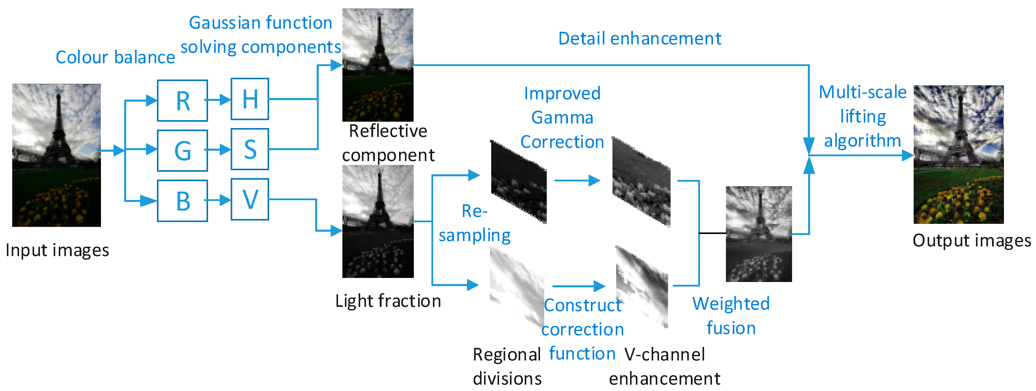
The framework of the algorithm in this paper is shown in Figure 1. First, an adaptive color balance method is employed to address the color differences in low-light images, ensuring a more uniform color distribution and yielding a low-light image with improved color consistency. Second, the image obtained is transformed from the RGB space to the HSV space, wherein the multi-scale Gaussian function is utilized in conjunction with the Retinex theory to accurately extract the lighting components and reflection components. Then, the obtained light components are divided into high-light areas and low-light areas and enhance them separately. Each block area of the image is weighted and fused, leading to its conversion back to the RGB space. And a multi-scale detail enhancement algorithm is then utilized to further enhance image details.
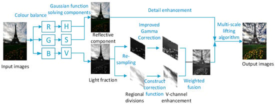
Figure 1.
The algorithmic framework of this paper.
2.1. Color Balance Correction
Images captured by digital image equipment may exhibit color imbalances due to defects in the equipment or adverse weather conditions [13]. In particular, in challenging weather like sandy weather, the acquired images often display significant color disparities [14]. This not only hampers image enhancement but also impacts its suitability for computer vision tasks such as image stitching [15]. To solve these problems, it is necessary to perform color balancing on the acquired image to eliminate or reduce the change in an object’s color due to the acquisition process, so as to enhance the original characteristics of the image. Firstly, the dynamic range values of each channel are normalized, then the green channel is used to compensate for the loss of the blue channel of the acquired image, and the red channel values are attenuated to some extent. The blue channel is expressed as [16]:
where and represent the average of the red and green channels of the original image , respectively. represents the ratio of the red channel to the green channel, and is used to adjust the color distribution of each channel. Finally, the traditional gray world algorithm is utilized to compensate the color cast of the light source.
2.2. HSV Space Conversion
After applying color balance, the issue of color cast is effectively resolved, laying the groundwork for brightness adjustment. When dealing with RGB images, direct brightness enhancement in the red channel (R), green channel (G) and blue channel (B) will result in image distortion due to excessive color enhancement. To address this concern, the HSV color space proves to be beneficial [17]. It separates the chroma (H), saturation (S) and brightness (V) into three independent channels within the color space, which ensures the balance of each color channel. As a result, the enhancement of the brightness component V only changes the brightness and darkness of the image. In this paper, the RGB space is converted to the HSV space by the following method [18], specifically expressed as follows:
where , and correspond to hue, saturation and brightness; , and represent red, green and blue channels, respectively.
2.3. Estimation of the Illumination Components
The Retinex theoretical model means that the image is composed of two parts: the light image and the reflection image, which is expressed as follows:
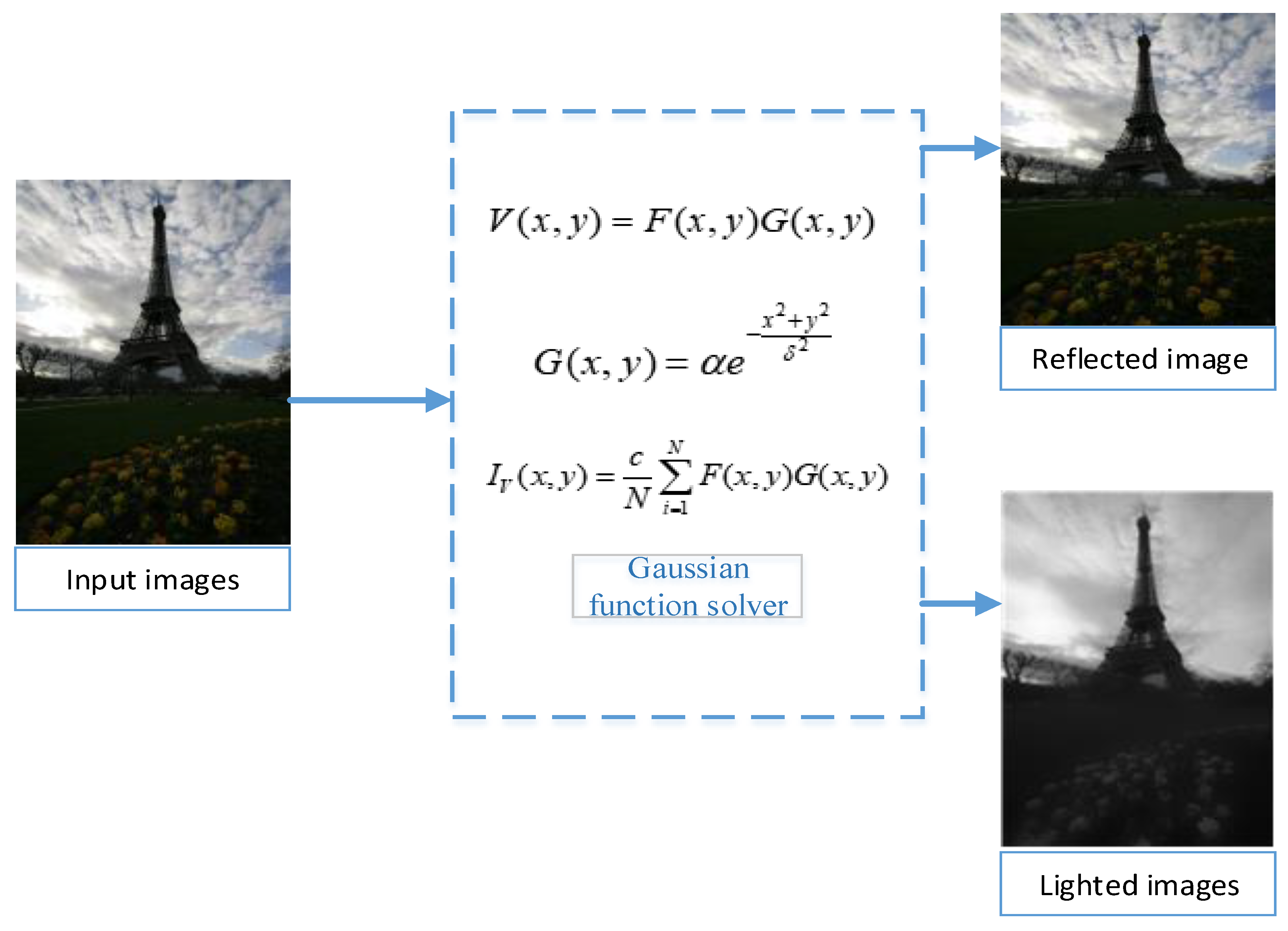
where represents the incident light component of the image, represents the reflection component of the object surface and is the luminance of the current coordinate point of the image. This formula demonstrates that accurate enhancement of the illumination component can lead to reduced impact on the reflection component after enhancement, consequently minimizing the impact on the color. As a result, this paper primarily focuses on image brightness adjustment through gamma correction applied to the illumination component. The resulting illumination component image can be observed in the flow chart depicted in Figure 2.
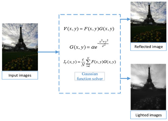
Figure 2.
Image decomposition model.
The multi-scale Gaussian function offers a significant advantage by effectively capturing more precise lighting components through dynamic range compression of the image. The method in this paper constructs a multi-scale Gaussian function to extract the light components, and the decomposition model of the image using the Gaussian function is shown in Figure 2. The Gaussian function is expressed as follows:
Convolving the image with a Gaussian function can estimate the value of the illumination component, which is expressed as follows:
where denotes the scale factor and is inversely related to the dynamic range of the image; the smaller the , the clearer the image. is the parameter that satisfies the Gaussian function . Convolving the image with a Gaussian function provides an estimate of the value of the illumination component.
To balance the integrity and difference of the extracted illumination components, an -dimensional Gaussian function with weighted functions is employed to extract the illumination components of the image, and finally, the estimated value of the illumination components is obtained. The expression is as follows:
where denotes the weight coefficient for extracting the illumination component under the -dimensional scale, denotes the dimension number of the Gaussian function, and denotes the balance parameter. To achieve a dynamic balance between the amount of calculation and the acquisition of illumination components, the values taken in this paper are = 4, = 1.
2.4. Improved Adaptive Region Correction
The gamma function is widely used for correcting the differences between bright and dark images, proving effective in various image enhancement algorithms. However, in traditional non-uniform-illumination image enhancement research, the exponent of the gamma function is often set as a constant based on the specific image scene. The drawback of this fixed setting is its limited capability to enhance only one or a certain type of image scene, lacking adaptability to multiple scenarios [19]. Given that the pixel mean value of a uniformly illuminated image should be about 1/2 after normalization [20], the correction algorithm in this paper introduces an idea of processing illumination components in blocks to realize image low-light enhancement and high-light suppression.
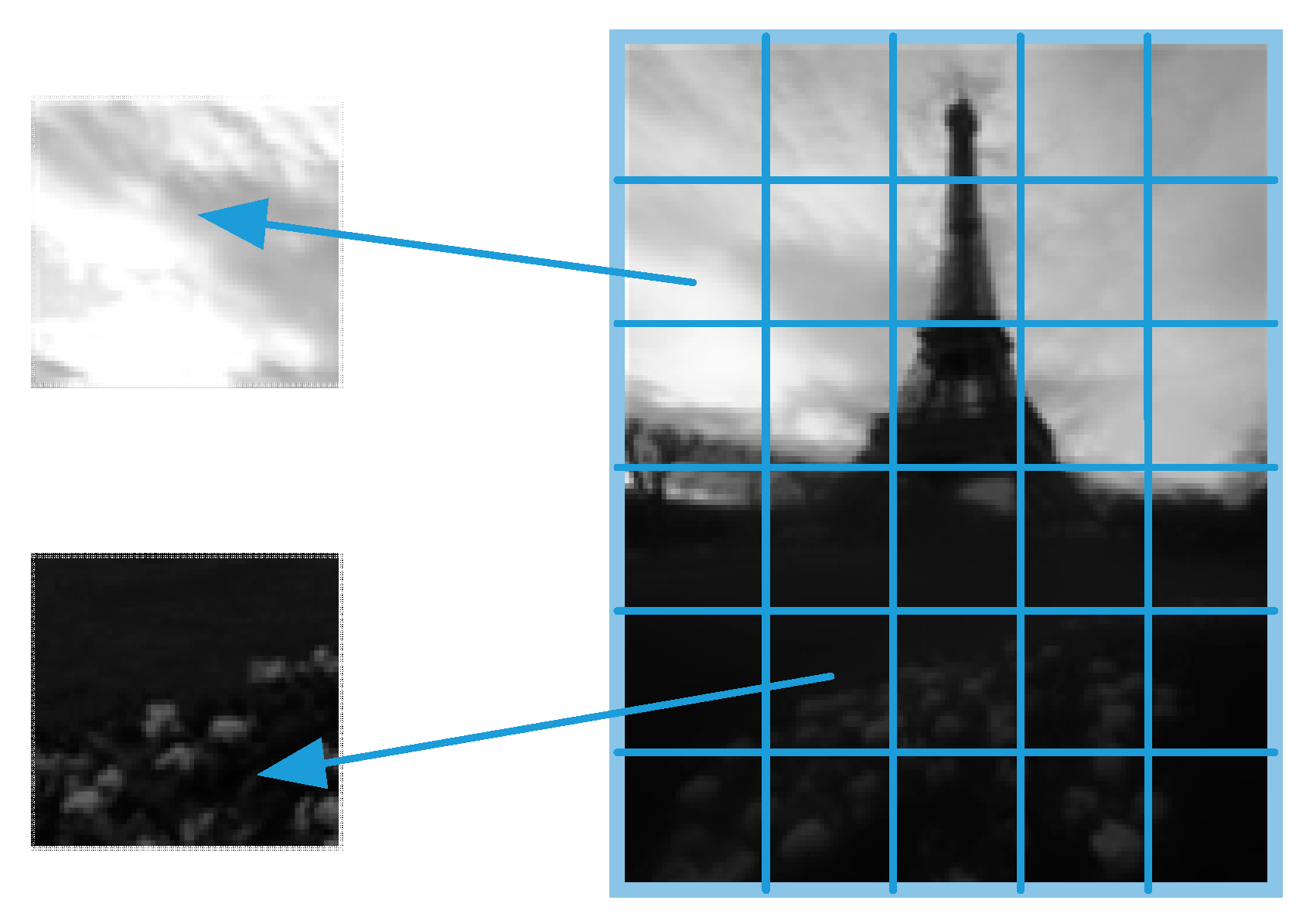
In this section, a quantitative analysis of the pixel average value of the illumination images obtained in Section 2.3 is carried out first, and the specific steps are as follows: firstly, the luminance component map is divided into areas [21] with the size of MxN on the right side in Figure 3; then, the segmented areas are classified into medium-high luminance area and low-luminance area on the basis of pixel mean values.
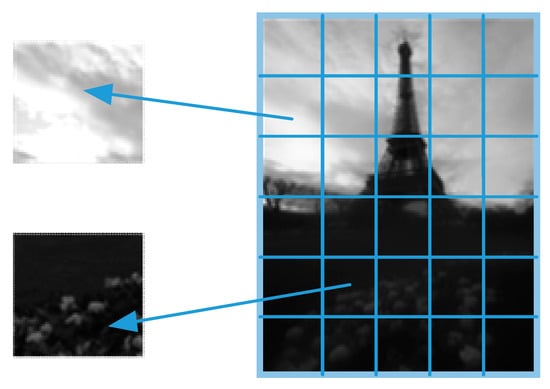
Figure 3.
Blocking of light component maps.
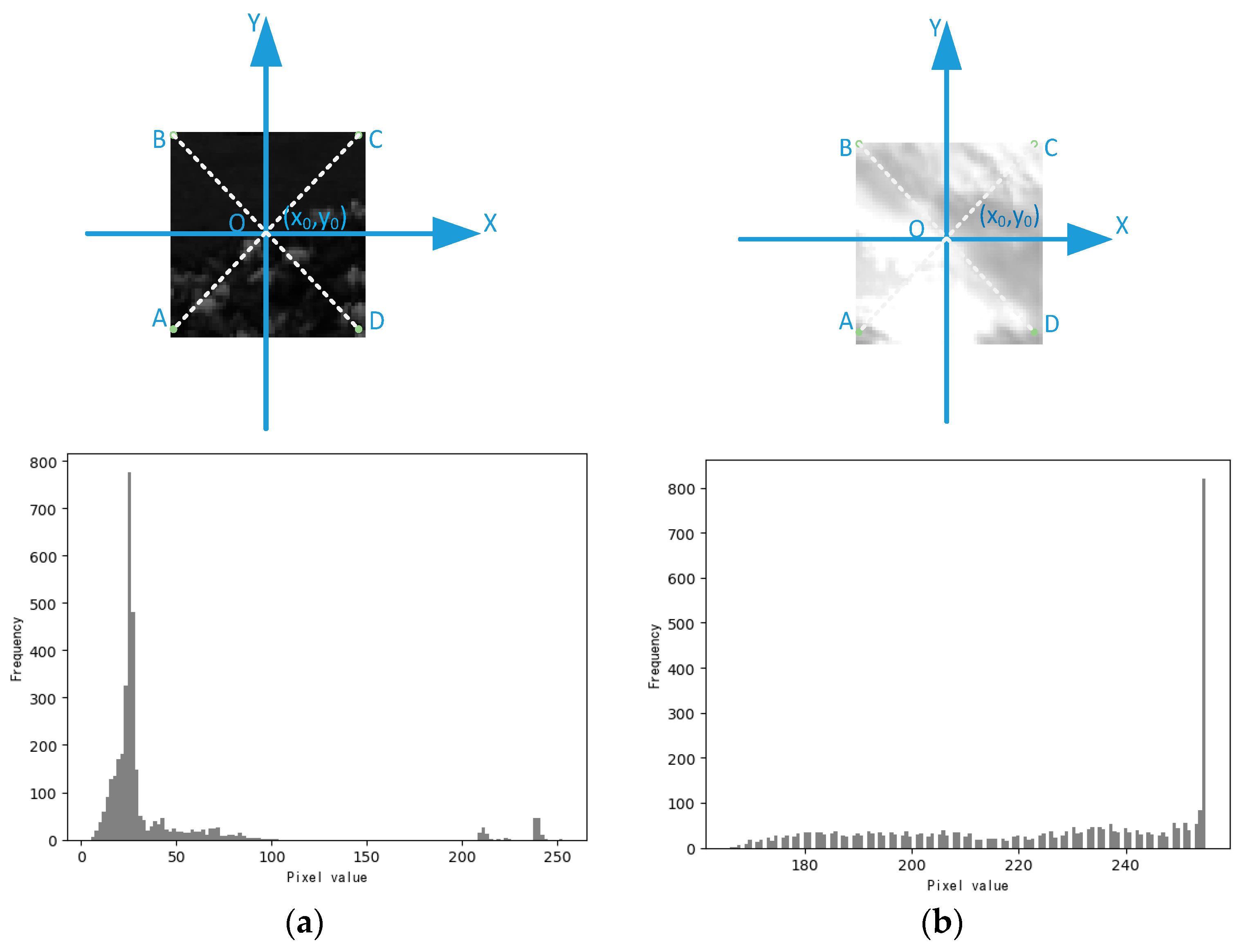
The coordinate model for the segmented area image is as follows:
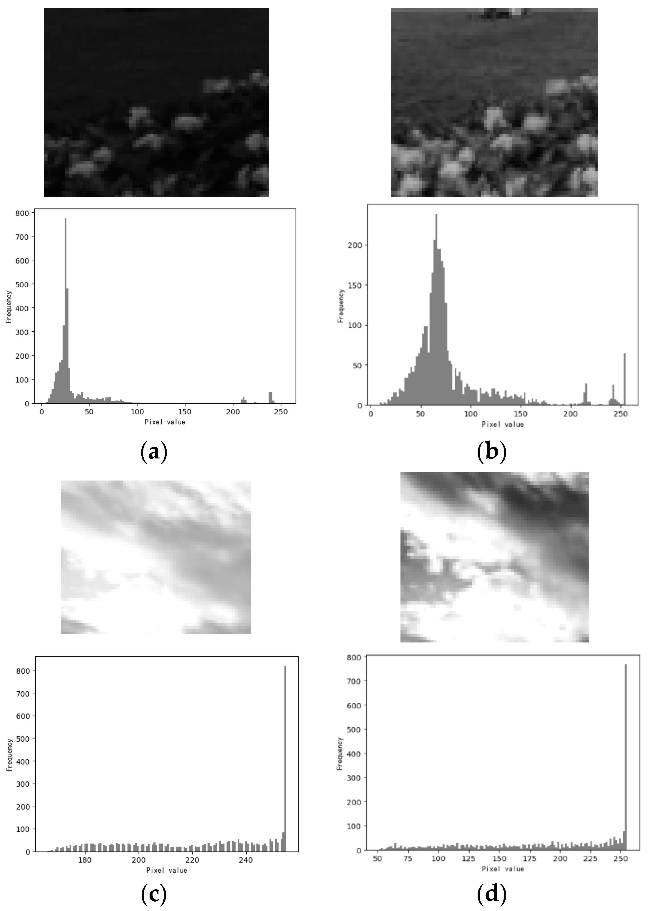
As shown in the coordinate model in Figure 4, the square is the location of the image segmentation area, and (a) and (b) in Figure 4 are the corresponding grayscale histograms of these areas, respectively. It is evident that the majority of the pixel intensities in area (a) are clustered in a narrow area, resulting in a darker image visually. On the other hand, the histogram distribution in area (b) is relatively uniform, leading to a brighter image perceived by the human eye. In Figure 4, the center point (x0, y0) in the area is used to calculate the average pixel value of each block area [22]. The formula for calculating the average brightness value of the block area is expressed as:
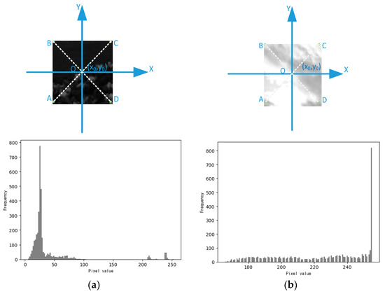
Figure 4.
Histogram corresponding to block areas: (a) the dark area of the image; (b) the bright area of the image.
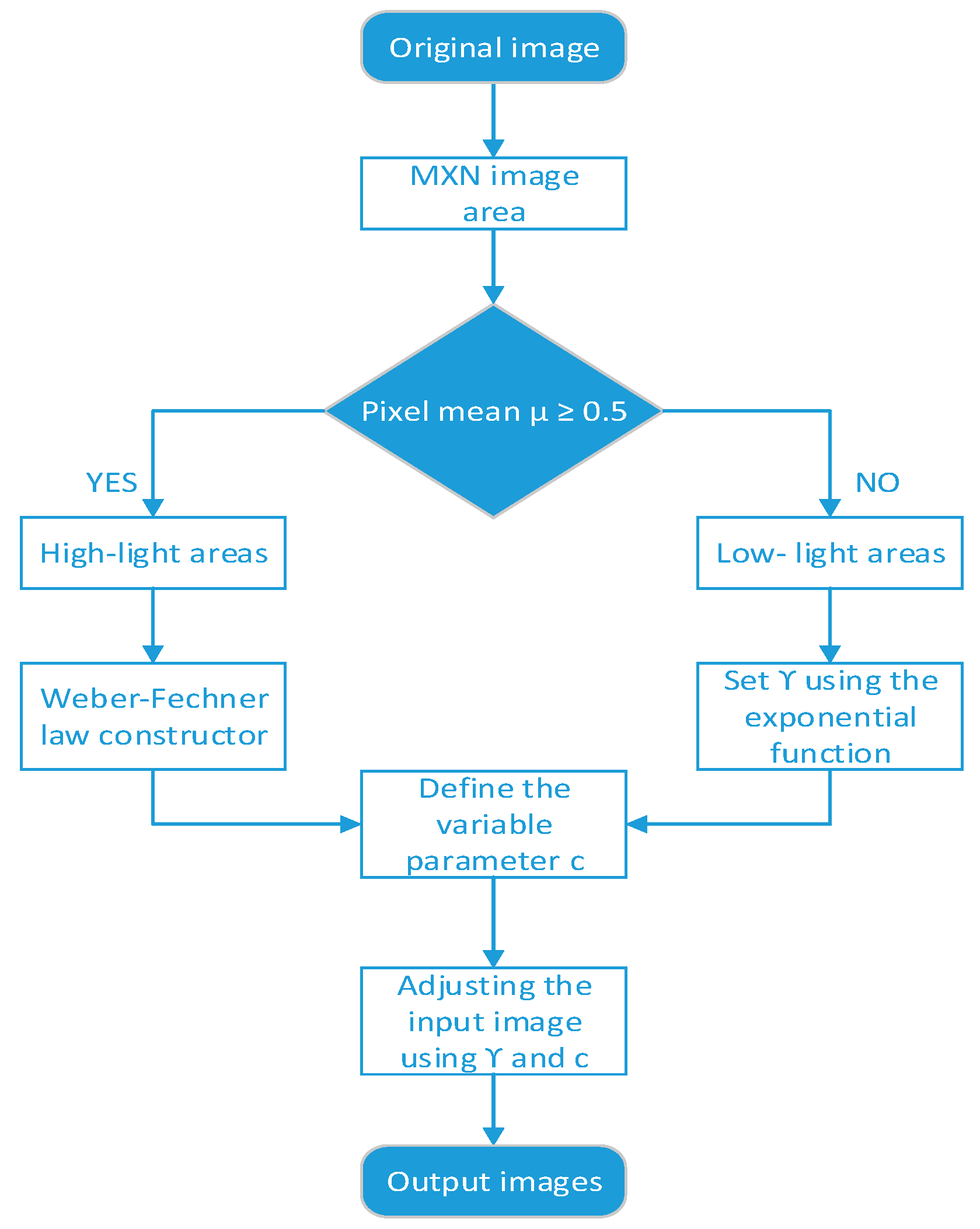
The implementation steps of the regional enhancement algorithm for non-uniform-illumination images studied in this section are shown in Figure 5:
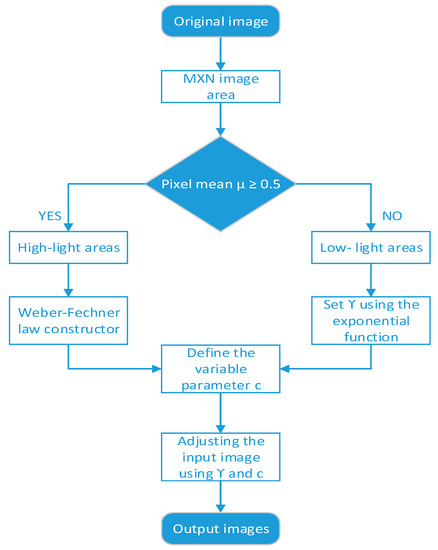
Figure 5.
Flow chart of region-based enhancement algorithm in this section.
2.4.1. Low-Light Area Enhancement
Based on the classification depicted in the flow chart in Figure 5, the pixel gray value should be spread over a larger range in the histogram for areas of low brightness in the image (). Therefore, the details in the bright areas can be acquired by increasing the brightness appropriately.
The gamma correction expression is as follows:
where denotes the intensity of the output image, denotes the intensity of the input image, and the overall brightness of the image is adjusted by using the gamma index number and the variable parameter .
To increase the brightness of such low-light areas, the value of is used to adjust the image brightness. Based on the principle that the lower the value of , the lower the brightness of the image, an enhancement method is designed to use the mean value of to assess the image brightness level for regional blocks, and a variance is introduced into the calculation of gamma factor to adjust the enhanced regional brightness. First, the normalized value of is utilized to classify the areas after division. Then, the area in which is enhanced according to the method in Section 2.4.1. The normalization function is defined as:
After experiments, the parameter in this paper is set as:
By Equations (11)–(14), the final transformation function is obtained as:
The method described above yields a notably favorable enhancement effect for the low-light areas.
2.4.2. High-Light Area Enhancement
In cases where the brightness of the block area falls within the medium-to-high light range, it indicates that the pixel gray levels are more widely spread throughout the histogram. As illustrated in Figure 4, the highlight area exhibit a relatively uniform distribution of the gray histogram, and the enhancement method in Section 2.4.1 cannot achieve a satisfactory enhancement effect. To address this situation, this section proposes a combination of the Weber–Fechner law, which leverages the logarithmic linear relationship between subjective luminance and target image luminance and introduces a coefficient K into the calculation of . By fully considering the pixel distribution in the enhanced area, a suitable correction function is proposed, which can both enhance the highlighted areas and retains detail. The formula is expressed as follows:
where and are both constants. To reduce the amount of calculation in Formula (16) and improve the adaptability of the enhancement algorithm, Formula (17) is used to fit the curve characteristics of Formula (16):
The value 255 is the gray level of the image, and is the adaptive adjustment parameter. Substituting into the final transformation function obtains:
where is the pixel value in the area and W is the total number of pixels in the area.
2.5. Weighted Fusion and Saturation Improvement
After performing brightness compensation on each block area of the original image for enhancement, slight differences in brightness may still exist between the blocks. While the overall image brightness is improved and uniform, differences may be noticeable at the junctions of each area, and the overall image can appear “fragmented”, requiring image fusion for a seamless result. In this regard, a weighted algorithm is used to carry out weighted fusion processing on the image, and the steps are as follows:
- Brightness compensation processing is performed on different blocks in Section 2.4 to obtain the enhancement results of different block regions, which are defined as F1, F2, F3,……, Fn.
- The weighted fusion formula calculates the image result after fusion processing, which is expressed as follows:
After the image has been weighted and fused, it is transferred back to the RGB space. While the brightness of the image has been improved through this process, there is a potential loss of saturation information. To address this problem, a multi-scale detail enhancement method of Gaussian difference [23] is used to increase details, as shown in Formula (22):
The multi-scale detail enhancement method primarily involves obtaining blurred images through the application of a Gaussian kernel to the original image, extracting different levels of image details , and , and merging the three-level images into an overall image, where , and take the value of 0.3, 0.3 and 0.4, respectively, to obtain the final enhanced image.
3. Results
To verify the effectiveness of the algorithm proposed in this paper, both subjective and objective experimental comparisons were conducted. All algorithms used in this study were implemented uniformly under the Python 3.7 software platform. The computer hardware configuration included an Intel Core i7 processor with 16GB RAM, operating on the Windows 7 operating system.
3.1. Illumination Components
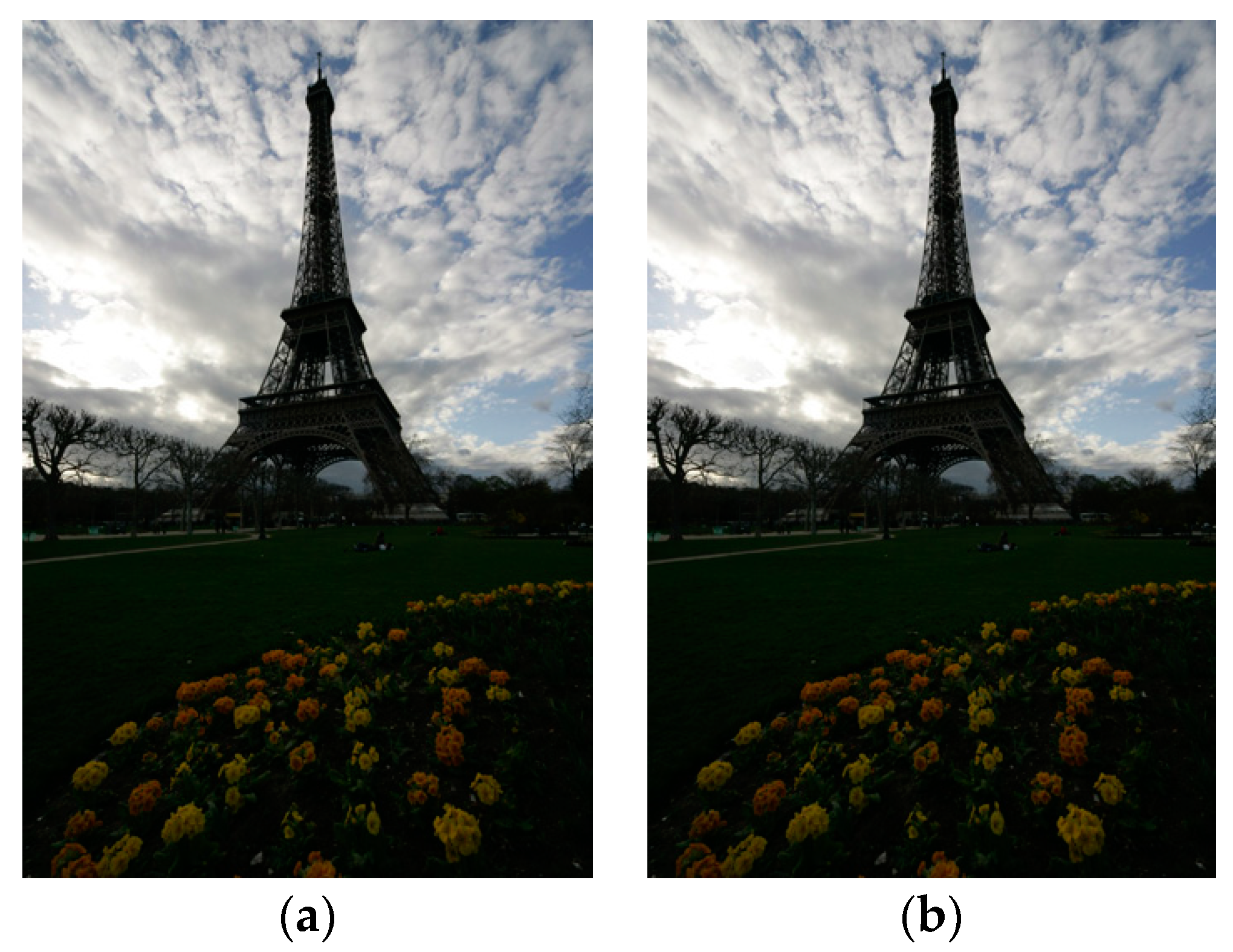
In this section, we conduct a comprehensive evaluation and analysis of the algorithms presented in Section 2 based on subjective visual perception. To lay the groundwork for subsequent processing, we implement color correction as a preliminary step on the input image, which significantly reduces distortion introduced during image enhancement due to color deviation. Figure 6 illustrates the result of color balance correction on the original image (a), represented by (b). This preliminary adjustment significantly contributes to the precise extraction of illumination components in the subsequent images, rendering the entire process more refined and accurate.
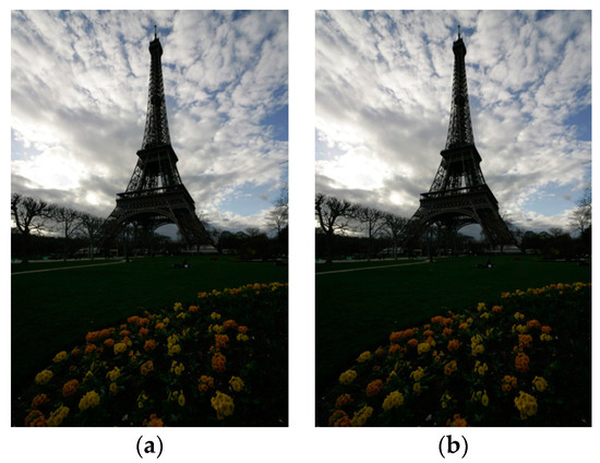
Figure 6.
Color cast correction: (a) original image; (b) image after color correction.
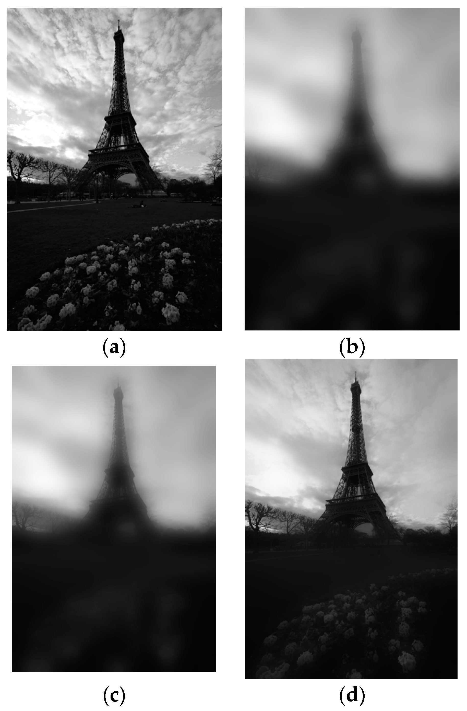
Figure 7b,c are the illumination component maps under different values of the Gaussian function scale factor (i.e., ), and Figure 7d illustrates the illumination component extracted by the improved Gaussian function method proposed in Section 2.
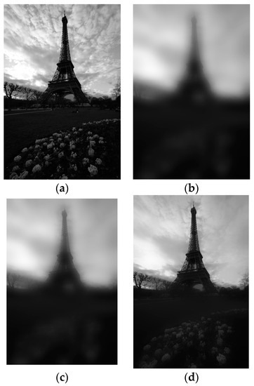
Figure 7.
Extraction of light components at different scales: (a) input original grayscale; (b) the original Gaussian formula sets the illumination component image when the Gaussian scale factor is 80; (c) the original Gaussian formula sets the illumination component image when the Gaussian scale factor is 200; (d) the precise light component map solved by the algorithm in this paper.
Figure 7 demonstrates that the multi-scale Gaussian function employed in this paper adeptly preserves the essential illumination information of the image, which meets the requirements of extracting illumination components.
3.2. Regional Enhancement Effect
After obtaining the precise light components, the algorithm presented in this paper performs distinct enhancements on both high- and low-light regions, as illustrated in Figure 8.
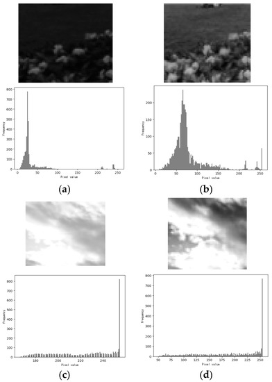
Figure 8.
Comparison of regional enhancements: (a) original low-light area; (b) low-light areas enhanced by the algorithm in this paper; (c) original highlight area; (d) the highlight area enhanced by the algorithm of this paper.
The image on the left showcases the original state before enhancement, while the image on the right demonstrates the improvements after the algorithm’s application. The grayscale histogram illustrates that the grayscale peak in the low-light area decreases and spans a broader range after enhancement by the algorithm in this paper. Meanwhile, the high-light area retains its original histogram distribution characteristics and accentuates the finer details within the image.
3.3. Image Fusion
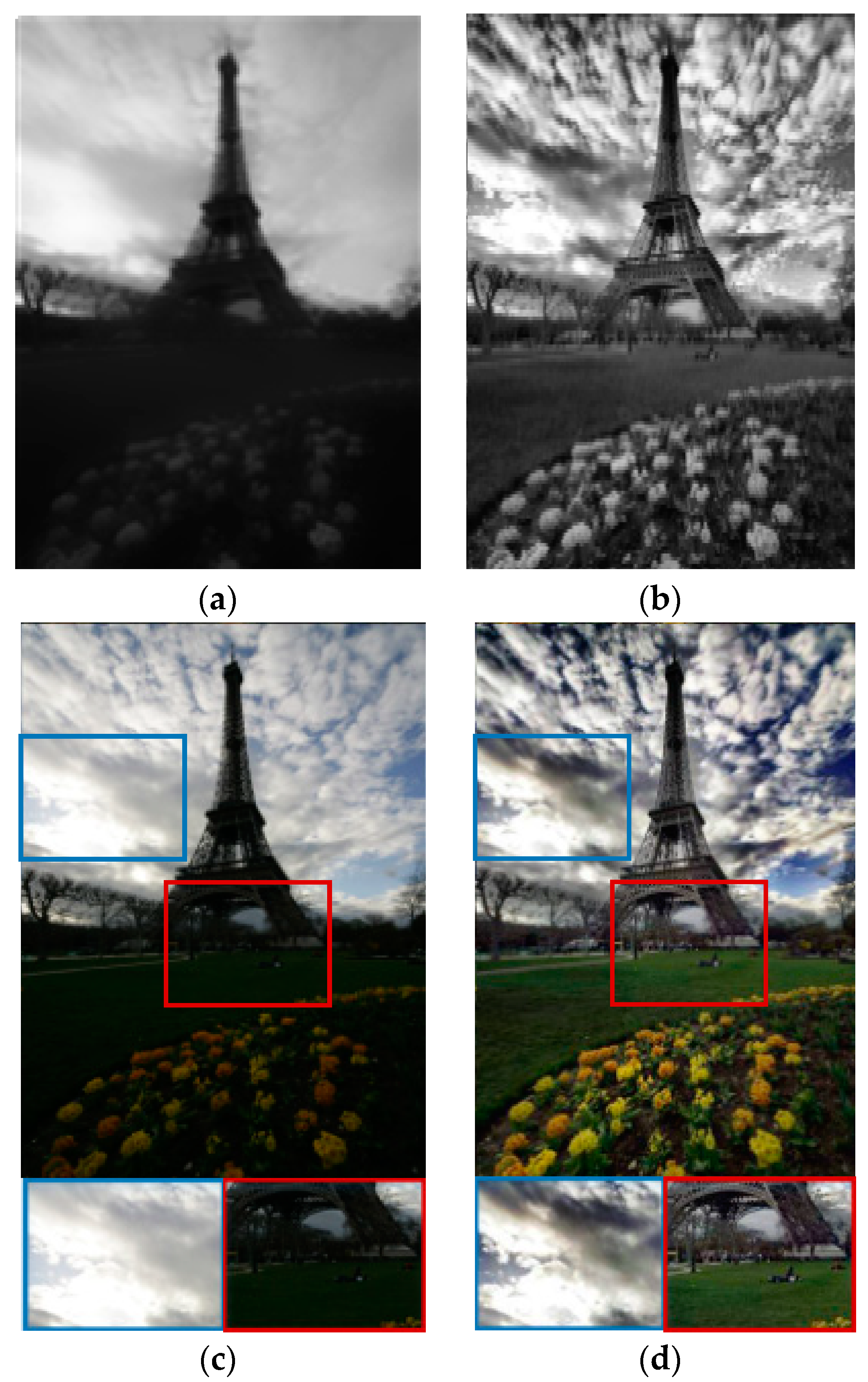
Figure 9 displays a contrast between the illumination component before and after enhancement via the algorithm in this paper, as well as the visual effect of the RGB image after improvement through the application of multi-scale method, which effectively caters to the adaptive enhancement of image brightness and darkness.
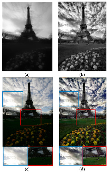
Figure 9.
Comparison of image details before and after weighted fusion: (a) raw light component; (b) illumination component enhancement fusion image; (c) raw RGB image; (d) image processed by multi-scale method.
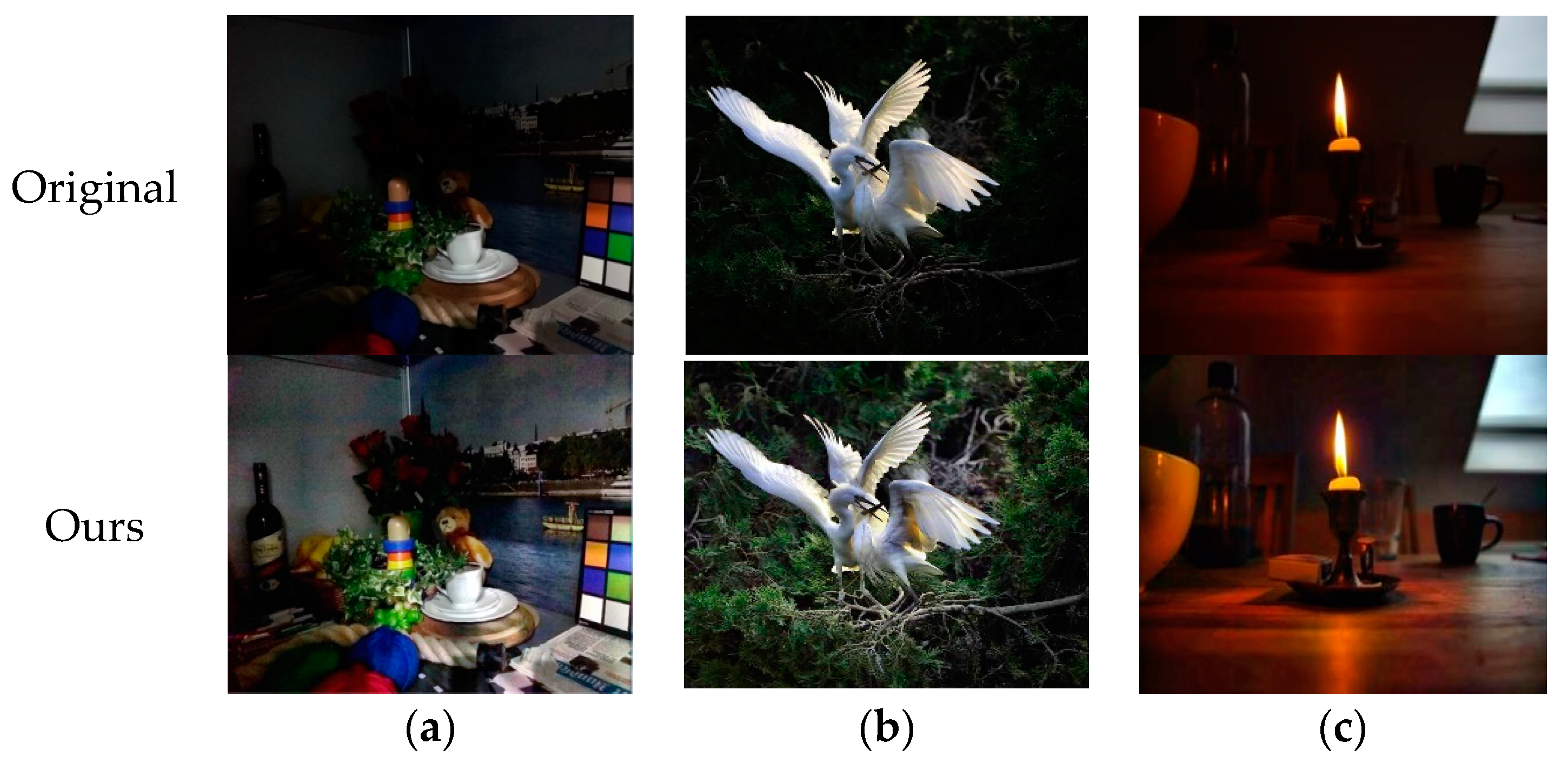
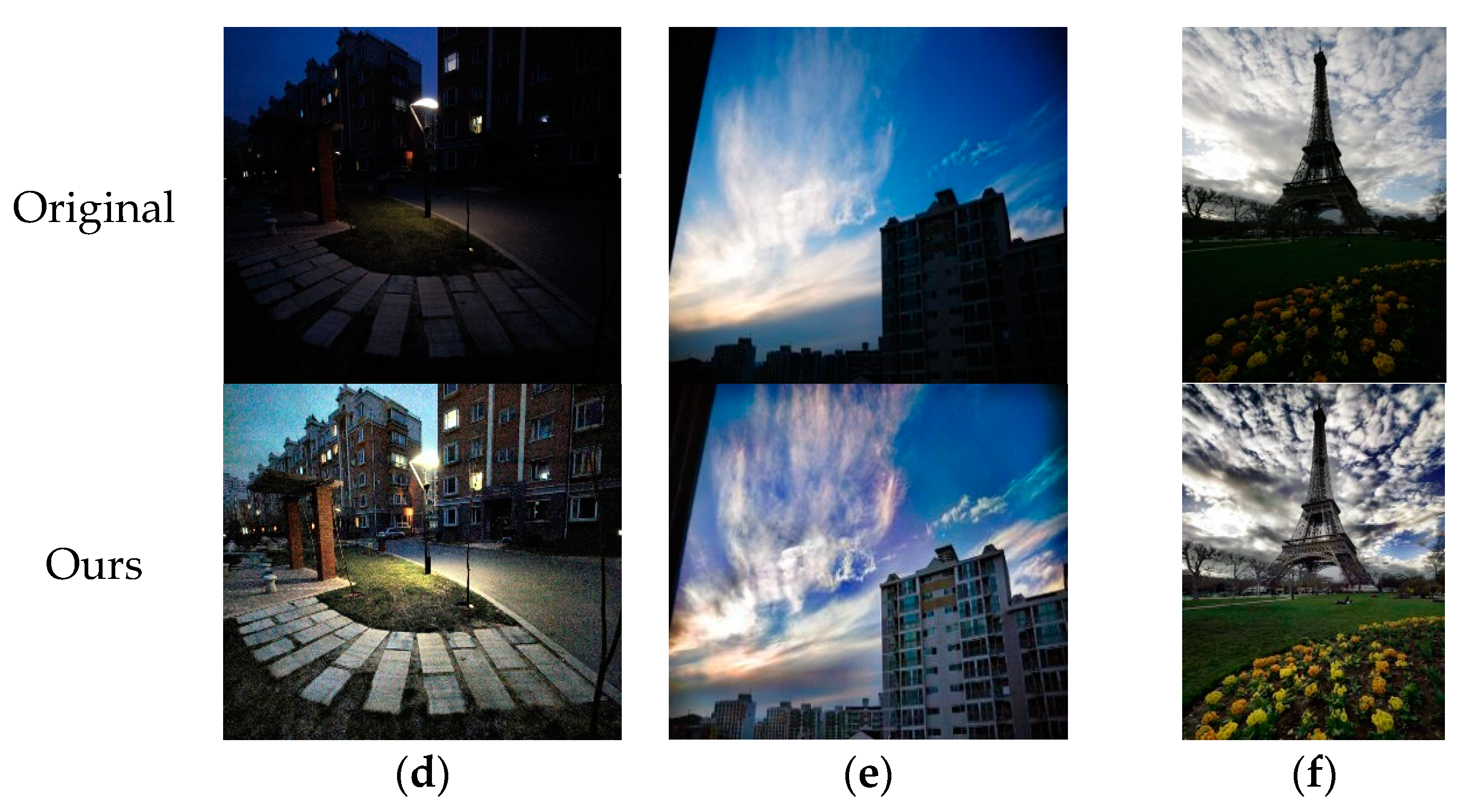
This paper selects some LIME dataset images as experimental materials, mainly those containing both low-light areas and high-light areas, which can more effectively verify the feasibility of the algorithm in this paper. The specific enhancement effects are presented in Figure 10, in which the first line contains the original images, and the second line contains the images enhanced by the algorithm in this paper.
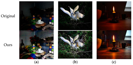
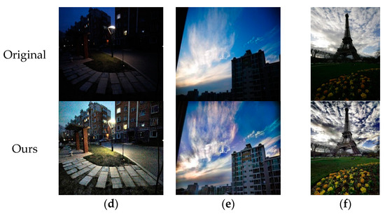
Figure 10.
Image enhancement effect of the algorithm in this paper: (a) plate; (b) bird; (c) candle; (d) streetlight; (e) sky; (f) tower.
In this paper, a subjective visual analysis was performed to compare the enhancement effects of this paper’s algorithm and other typical algorithms using two representative images, Lamp and Street. The comparison results are shown in Figure 11 and Figure 12.

Figure 11.
Enhancement effects of image Lamp via different methods: (a) dataset raw Lamp image; (b) algorithm in [24]; (c) algorithm in [25]; (d) algorithm in [26]; (e) our algorithm.

Figure 12.
Enhancement effects of image Street via different methods: (a) dataset raw Street image; (b) algorithm in [24]; (c) algorithm in [25]; (d) algorithm in [26]; (e) our algorithm.
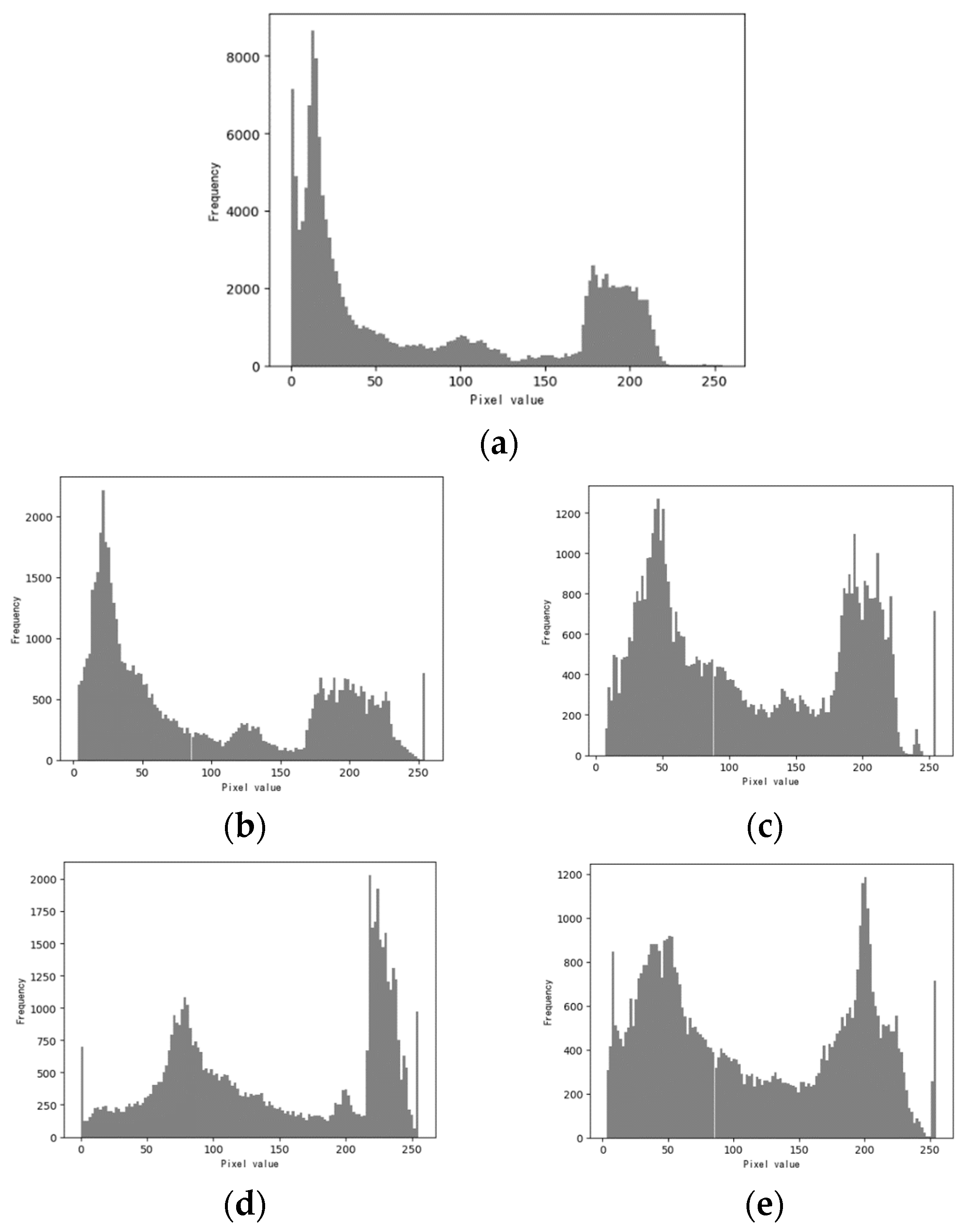
As illustrated in Figure 13, a comparison between the gray histograms before and after the enhancement of the Street image is presented.
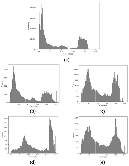
Figure 13.
Histogram comparison of image Street before and after enhancement: (a) histogram of the original Street image; (b) algorithm in [24]; (c) algorithm in [25]; (d) algorithm in [26]; (e) our algorithm.
3.4. Image Quality Metrics
The enhancement effects on the Street image in Figure 12 are evaluated through three quality metrics, the Structural Similarity Index (SSIM), the Peak Signal-to-Noise Ratio (PSNR), and Information Entropy (IE). The SSIM [27] is used to analyze image quality in terms of image contrast, brightness and structure. A higher SSIM value indicates a greater degree of image restoration, signifying improved visual fidelity. The SSIM solution is expressed as follows:
where is the luminance component, is the contrast component and is the chrominance component. and represent the mean values of the original image and the enhanced image , respectively; and represent the variance of the two images, respectively, and represents the covariance.
The PSNR is another vital metric utilized for assessment, which gauges the difference between the original image and the processed image by calculating the Mean Square Error (MSE). A higher PSNR value corresponds to a higher quantity of preserved image information and reduced distortion, leading to enhanced image quality.
where denotes the mean square error between the enhanced image and the original image; and denote the length and width of the image, respectively; and denote the pixel values of the original image, and the pixel values of the enhanced image, respectively.
Information Entropy (IE) reflects the average amount of information contained within an image and the complexity of its pixel distribution. The larger the information entropy, the clearer the image and the higher the quality.
The quality indices of the enhanced Street image using different algorithms are shown in Table 1.

Table 1.
Analysis of the indicators.

Table 2.
Comparison of mean values for metrics.
4. Discussion
In this paper, a subjective visual analysis was performed to discuss the enhancement effects of this paper’s algorithm and other typical algorithms using two representative images, Lamp and Street. The comparison results are shown in Figure 11 and Figure 12. Both images contain bright and dark areas, which is a test of the algorithms’ ability to suppress highlights during enhancement. The enhancement results of the Lamp and Street images using each method are presented in Figure 11 and Figure 12, respectively. In the comparison shown in Figure 12, the AEIHE algorithm proposed in [24] exhibits limited advantages in the enhancement effect. Meanwhile, the weighted enhancement algorithm based on CNN classification in [25] demonstrates effective highlight suppression for the sky in the Street image, but its handling of low-light details falls slightly short. Regarding the AGC algorithm based on gamma function improvement from [26], it effectively enhances the low-light areas in the Lamp image but leads to over-enhancement of the sky in the Street image, resulting in a significant loss of fine details in that area. Upon comparing the results displayed in Figure 11 and Figure 12, it becomes apparent that the algorithm in this paper excels in increasing the brightness of the original image while preserving crucial sky details in the Street image. The method presented herein achieves a remarkable balance, showcasing enhanced texture and superior detail clarity across the entire image.
As illustrated in Figure 13, a comparison between the gray histograms before and after the enhancement of the Street image is presented. Upon inspection, it becomes evident that the original Street image histogram exhibits a substantial difference between its peak and valley values. Additionally, the gray values of pixels above 100 gray levels are relatively sparse and inadequately scattered, resulting in a darker overall appearance of the original image. Moving on to the histogram of the image enhanced by the AEIHE algorithm proposed in [24], the main peak position is shifted to the left, resulting in a decreased pixel distribution within the 100–200 gray level interval, ultimately reducing the overall brightness of the image. In the histogram processed by the algorithm introduced by [25], the main peaks are located at both ends, with the left-end peak being higher than the right, resulting in insufficient detail improvement. In the histogram processed by the algorithm introduced in [26], the main peak at the right end is partly higher than the left end, causing an over-enhancement of the high-light area. On the other hand, the algorithm presented in this paper excels in achieving a relatively low pixel gray peak-to-valley difference during image enhancement, highlighting the detail in the low-light and high-light areas through effective utilization of the gray space.
In the image metric comparison, Table 1 displays the quality indicators of different algorithms using the images depicted in Figure 12. The algorithm proposed in this paper slightly underperforms compared to the one in [26] in terms of SSIM indicators. However, it outperforms other comparison methods significantly in terms of the PSNR and information entropy indicators, which suggests that the algorithm in this paper has outstanding comprehensive enhancement effect and can retain more image detail. This paper evaluates the proposed algorithm’s effectiveness by conducting experimental comparisons with several classic algorithms. The images from Figure 10 are utilized for this verification process, and the average values of the indicators after applying each algorithm’s enhancement are recorded in Table 2. The analysis reveals that the algorithm proposed in this paper surpasses other algorithms in terms of comprehensive enhancement capabilities.
The method proposed in this paper is not perfect and has some shortcomings. As can be seen from Figure 10, where there is very low light, the saturation of the image after enhancement still needs to be improved, although it is considered a better choice. These deficiencies are still the next task to be studied, and with the development of image enhancement algorithms, creating more perfect methods to solve existing enhancement problems is the way forward.
5. Conclusions
This paper presents a non-uniform-illumination image enhancement algorithm based on the Retinex theory, addressing the problems of low brightness and unclear details in non-uniform-illumination images and shortcomings observed in the application of traditional methods in enhancing non-uniform-illumination images, such as local over-enhancement and insufficient parameter adaptability. The proposed algorithm follows a systematic approach to achieve comprehensive image enhancement. It begins by employing the color balance method to address the color differences in the non-uniform-illumination image. After obtaining a uniformly colored non-uniform-illumination image, the image is converted from the RGB space to the HSV space. In combination with the Retinex theory, the multi-scale Gaussian function is utilized to obtain the precise illumination component and reflection component in the HSV space. The illumination component map is then divided into distinct blocks, categorizing them into high-light and low-light areas for independent enhancement. The low-light area is enhanced using an adaptive gamma correction algorithm, while the high-light area is enhanced by a function based on the Weber–Fechner law. Furthermore, image fusion and detail improvement are applied to obtain high-quality enhanced images. Through a comparison experiment with typical algorithms, the efficacy of the algorithm proposed in this paper is proven. Specifically, it achieves a better balance of the overall brightness in the image while retaining image details, avoiding the distortion caused by excessive enhancement. As a result, the enhanced image retains more information with clearer details.
Author Contributions
Project management guide, X.J.; Writing—original draft, S.G.; Writing—review and editing, H.Z.; Survey—collecting data, W.X. All authors have read and agreed to the published version of the manuscript.
Funding
This project is supported by the Science and Technology Project of State Grid Jilin Electric Power Co., LTD., Jilin, China (Contract No.: 512342220003).
Institutional Review Board Statement
Not applicable.
Informed Consent Statement
Not applicable.
Data Availability Statement
Some or all data, models, or code generated or used during the study are available from the corresponding author by request.
Acknowledgments
Here we would like to express our sincere thanks to Xiangyu Lv and Minxu Liu for their help in providing data and relevant materials in the research work, as well as funding.
Conflicts of Interest
The authors declare no conflict of interest.
References
- Zhuo, L.; Hu, X.; Li, J.; Zhang, J.; Li, X. A Naturalness-Preserved Low-Light Enhancement Algorithm for Intelligent Analysis. Chin. J. Electron. 2019, 28, 316–324. [Google Scholar] [CrossRef]
- Mu, Q.; Wang, X.; Wei, Y.; Li, Z. Low and non-uniform illumination color image enhancement using weighted guided image filtering. Comput. Vis. Media 2021, 7, 529–546. [Google Scholar] [CrossRef]
- Wang, D.; Yan, W.; Zhu, T.; Xie, Y.; Song, H.; Hu, X. An Adaptive Correction Algorithm for Non-Uniform Illumination Panoramic Images Based on the Improved Bilateral Gamma Function. In Proceedings of the DICTA 2017—2017 International Conference on Digital Image Computing: Techniques and Applications, Sydney, Australia, 29 November–1 December 2017. [Google Scholar] [CrossRef]
- Rivera, A.R.; Ryu, B.; Chae, O. Content-Aware Dark Image Enhancement Through Channel Division. IEEE Trans. Image Process. 2012, 21, 3967–3980. [Google Scholar] [CrossRef] [PubMed]
- Jmal, M.; Souidene, W.; Attia, R. Efficient cultural heritage image restoration with nonuniform illumination enhancement. J. Electron. Imaging 2017, 26, 11020. [Google Scholar] [CrossRef]
- Shi, Z.; Zhu, M.M.; Guo, B.; Zhao, M.; Zhang, C. Nighttime low illumination image enhancement with single image using bright/dark channel prior. EURASIP J. Image Video Process. 2018, 2018, 13. [Google Scholar] [CrossRef]
- Lu, H.; Li, Y.; Uemura, T.; Kim, H.; Serikawa, S. Low illumination underwater light field images reconstruction using deep convolutional neural networks. Futur. Gener. Comput. Syst. 2018, 82, 142–148. [Google Scholar] [CrossRef]
- Alismail, H.; Browning, B.; Lucey, S. Robust tracking in low light and sudden illumination changes. In Proceedings of the 2016 4th International Conference on 3D Vision, 3DV 2016, Stanford, CA, USA, 25–28 October 2016. [Google Scholar]
- Zhi, N.; Mao, S.; Li, M. Enhancement algorithm based on illumination adjustment for non-uniform illuminance video images in coal mine. Meitan Xuebao/J. China Coal Soc. 2017, 42, 2190–2197. [Google Scholar]
- Coelho, L.d.S.; Sauer, J.G.; Rudek, M. Differential evolution optimization combined with chaotic sequences for image contrast enhancement. Chaos Solitons Fractals 2009, 42, 522–529. [Google Scholar] [CrossRef]
- Oktay, O.; Ferrante, E.; Kamnitsas, K.; Heinrich, M.; Bai, W.; Caballero, J.; Cook, S.A.; De Marvao, A.; Dawes, T.; O’Regan, D.P.; et al. Anatomically Constrained Neural Networks (ACNNs): Application to Cardiac Image Enhancement and Segmentation. IEEE Trans. Med. Imaging 2018, 37, 384–395. [Google Scholar] [CrossRef]
- Nickfarjam, A.M.; Ebrahimpour-Komleh, H. Multi-resolution gray-level image enhancement using particle swarm optimization. Appl. Intell. 2017, 47, 1132–1143. [Google Scholar] [CrossRef]
- He, X.; Huang, R.; Yu, M.; Zeng, W.; Zhang, S. Multi-State Recognition Method of Substation Switchgear Based on Image Enhancement and Deep Learning. Adv. Transdiscipl. Eng. 2022, 33, 572–577. [Google Scholar] [CrossRef]
- Jeon, J.-J.; Park, T.-H.; Eom, I.-K. Sand-Dust Image Enhancement Using Chromatic Variance Consistency and Gamma Correction-Based Dehazing. Sensors 2022, 22, 9048. [Google Scholar] [CrossRef] [PubMed]
- Gao, G.; Lai, H.; Wang, L.; Jia, Z. Color balance and sand-dust image enhancement in lab space. Multimed. Tools Appl. 2022, 81, 15349–15365. [Google Scholar] [CrossRef]
- Ancuti, C.O. Color Balance and Fusion for Underwater Image Enhancement. IEEE Trans. Image Process. 2018, 27, 379–393. [Google Scholar] [CrossRef]
- Zhi, S.; Cui, Y.; Deng, J.; Du, W. An FPGA-Based Simple RGB-HSI Space Conversion Algorithm for Hardware Image Processing. IEEE Access 2020, 8, 173838–173853. [Google Scholar] [CrossRef]
- Niu, H.; Wang, C. Sand-dust image enhancement algorithm based on HSI space. J. Beijing Jiaotong Univ. 2022, 46, 1–8. [Google Scholar]
- Rahman, S.; Rahman, M.; Abdullah-Al-Wadud, M.; Al-Quaderi, G.D.; Shoyaib, M. An adaptive gamma correction for image enhancement. EURASIP J. Image Video Process. 2016, 2016, 35. [Google Scholar] [CrossRef]
- Lyu, J. Detection model for tea buds based on region brightness adaptive correction. Nongye Gongcheng Xuebao/Trans. Chin. Soc. Agric. Eng. 2021, 37, 278–285. [Google Scholar]
- Jiang, L.; Yuan, H.; Li, C. Circular hole detection algorithm based on image block. Multimed. Tools Appl. 2018, 78, 29659–29679. [Google Scholar] [CrossRef]
- Perlmutter, D.S.; Kim, S.M.; Kinahan, P.E.; Alessio, A.M. Mixed Confidence Estimation for Iterative CT Reconstruction. IEEE Trans. Med. Imaging 2016, 35, 2005–2014. [Google Scholar] [CrossRef]
- Kim, Y.; Koh, Y.J.; Lee, C.; Kim, S.; Kim, C.-S. Dark image enhancement based onpairwise target contrast and multi-scale detail boosting. In Proceedings of the International Conference on Image Processing, ICIP, Quebec City, QC, Canada, 27–30 September 2015. [Google Scholar] [CrossRef]
- Majeed, S.H.; Isa, N.A.M. Adaptive Entropy Index Histogram Equalization for Poor Contrast Images. IEEE Access 2021, 9, 6402–6437. [Google Scholar] [CrossRef]
- Rahman, Z.; Yi-Fei, P.; Aamir, M.; Wali, S.; Guan, Y. Efficient Image Enhancement Model for Correcting Uneven Illumination Images. IEEE Access 2020, 8, 109038–109053. [Google Scholar] [CrossRef]
- Cao, G.; Huang, L.; Tian, H.; Huang, X.; Wang, Y.; Zhi, R. Contrast enhancement of brightness-distorted images by improved adaptive gamma correction. Comput. Electr. Eng. 2018, 66, 569–582. [Google Scholar] [CrossRef]
- Setiadi, D.R.I.M. PSNR vs. SSIM: Imperceptibility quality assessment for image steganography. Multimed. Tools Appl. 2021, 80, 8423–8444. [Google Scholar] [CrossRef]
- Guo, X.; Li, Y.; Ling, H. LIME: Low-Light Image Enhancement via Illumination Map Estimation. IEEE Trans. Image Process. 2017, 26, 982–993. [Google Scholar] [CrossRef]
- Petro, A.B.; Sbert, C.; Morel, J.-M. Multiscale Retinex. Image Process. Line 2014, 4, 71–88. [Google Scholar] [CrossRef]
- Liu, X.; Wang, Z.; Wang, L.; Huang, C.; Luo, X. A Hybrid Retinex-Based Algorithm for UAV-Taken Image Enhancement. IEICE Trans. Inf. Syst. 2021, E104.D, 2024–2027. [Google Scholar] [CrossRef]
Disclaimer/Publisher’s Note: The statements, opinions and data contained in all publications are solely those of the individual author(s) and contributor(s) and not of MDPI and/or the editor(s). MDPI and/or the editor(s) disclaim responsibility for any injury to people or property resulting from any ideas, methods, instructions or products referred to in the content. |
© 2023 by the authors. Licensee MDPI, Basel, Switzerland. This article is an open access article distributed under the terms and conditions of the Creative Commons Attribution (CC BY) license (https://creativecommons.org/licenses/by/4.0/).

