
Design and Analysis of Internal–External Composite Meshing Hy-Vo Chain

Abstract
:Featured Application
Abstract
1. Introduction
2. Basic Design
2.1. Basic Parameters
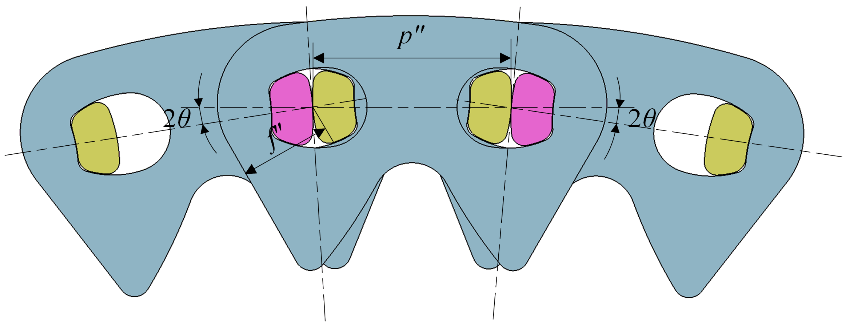
2.2. Meshing Parameters
3. Internal Meshing Profile
3.1. Instantaneous Meshing Condition
3.2. Continuous Meshing Condition
3.3. Proper Internal Meshing Profile
4. Meshing Characteristics
5. Multi-Body Dynamics Experiments
5.1. Setting and Calculating
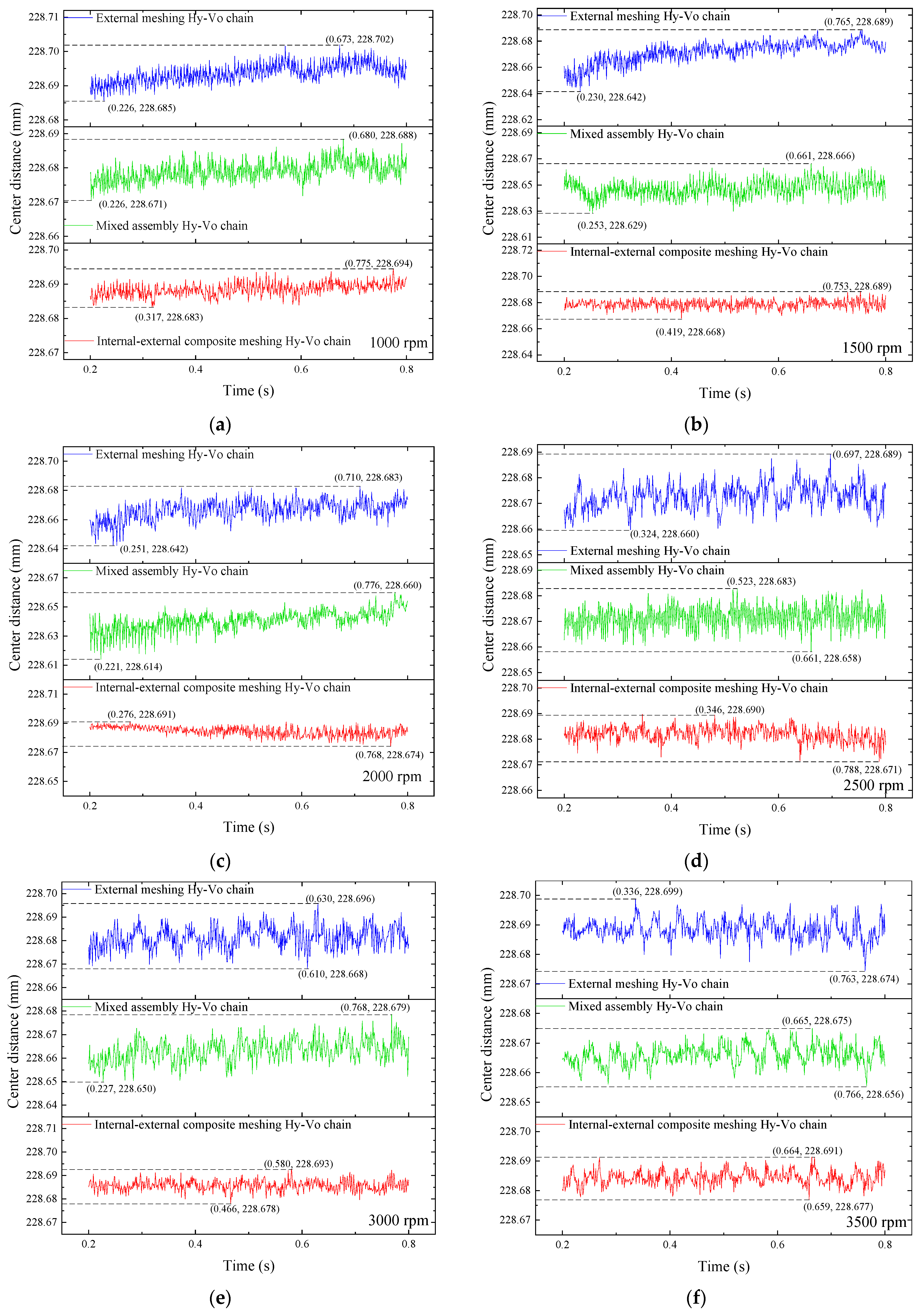
5.2. System Center Distance Fluctuation Analysis
5.3. Contact Analysis
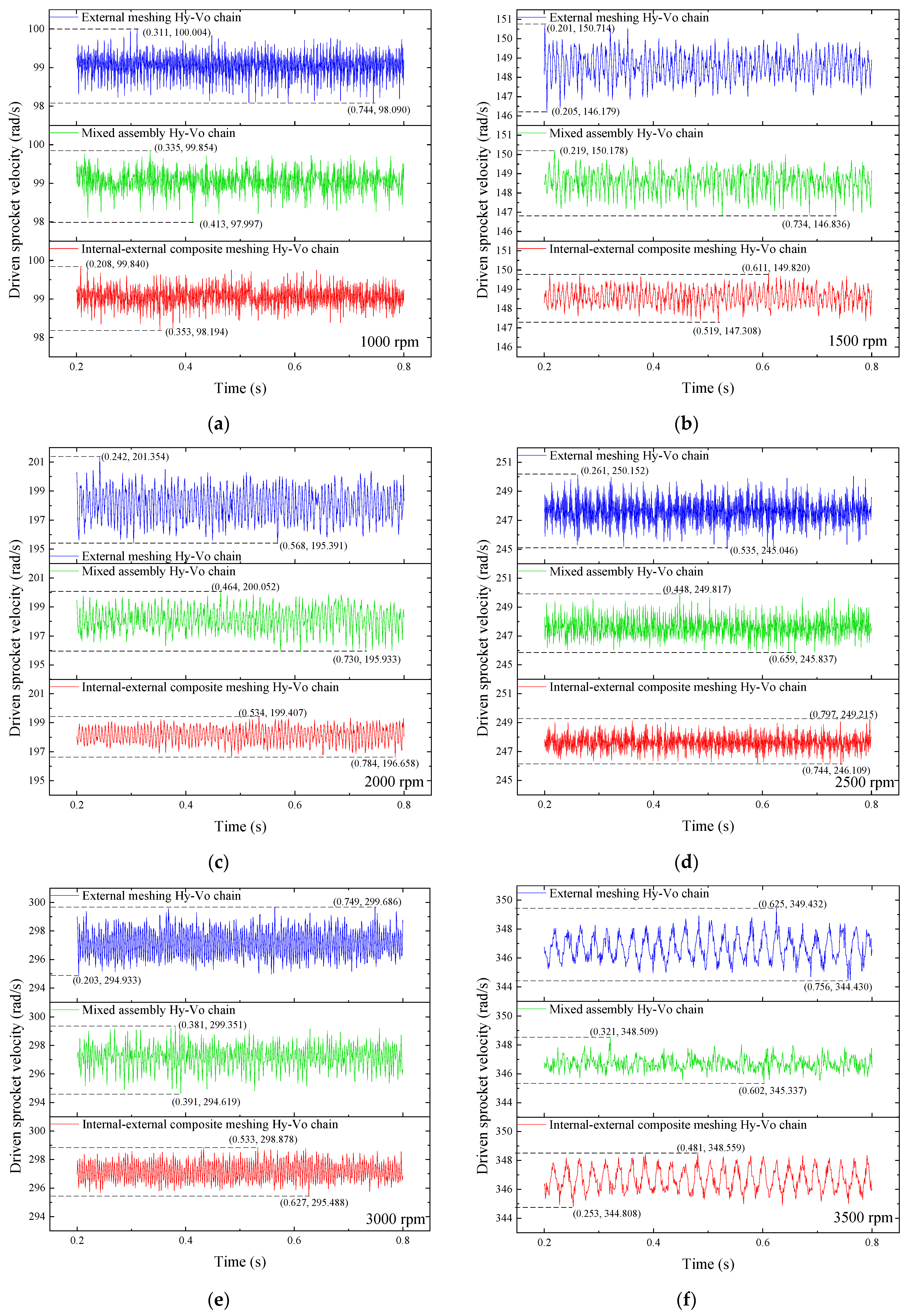
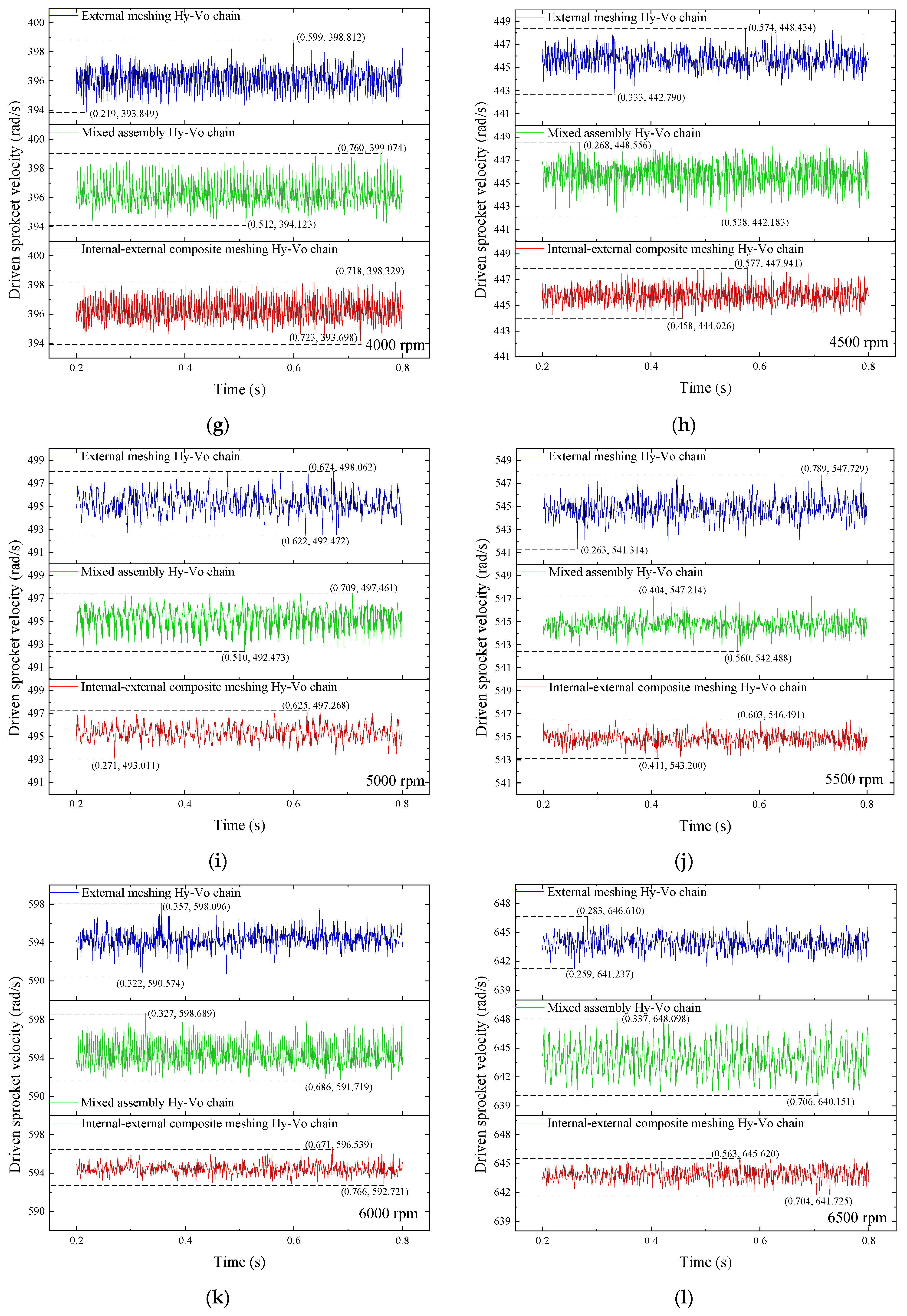
5.4. Rotation Velocity of Driven Sprocket Analysis
6. Conclusions
- p1 = p and α1 = α are the necessary conditions for the existence of the internal–external composite meshing Hy-Vo chain. The proper internal meshing profile of the internal–external composite meshing Hy-Vo chain should be a straight line, and its convexity should satisfy Equation (19). Based on the dynamics simulation results, taking the external meshing Hy-Vo chain system as the benchmark, for the internal–external composite meshing Hy-Vo chain system, the meshing performance is improved by an average of 42.38%, the transmission stability is improved by an average of 40.73%, and the polygon action is improved by an average of 32.72%. For the mixed assembly Hy-Vo chain system, the meshing performance, the transmission stability, and the polygon action are only improved by an average of 13.08%, 8.12%, and 8.60%, respectively;
- The mixed assembly Hy-Vo chain cannot stably enhance the system meshing performance, transmission stability, and polygon action. According to the dynamics simulation results, compared with the external meshing Hy-Vo chain system, the system meshing performance, transmission stability, and polygon action of the mixed assembly Hy-Vo chain system can only be improved at some special speeds. At other speeds, the system meshing performance, transmission stability, and polygon action for the mixed assembly Hy-Vo chain system will become worse. In the worst case, the system meshing performance is reduced by 23.40%, the system transmission stability is worsened by 37.57%, and the system polygon action is worsened by 47.91% instead. Therefore, the proper internal meshing profile of the mixed assembly Hy-Vo chain is not an arc, and the relative design approach is false;
- The meshing between the internal–external composite meshing Hy-Vo chain and the involute sprocket is continuous but incomplete; its effect on reducing the polygon action and the transmission performance is limited. The main reason for that is because the tooth shape of the involute sprocket in the Hy-Vo chain transmission system is significantly smaller than that in the round pin jointed silent chain transmission system;
- The classical meshing theory about the internal–external composite meshing characteristics of the Hy-Vo chain is not completely correct. Under the classical meshing theory, the internal–external composite meshing mechanism should enhance the system meshing performance, transmission stability, and polygon action, as well as the meshing impact between the chain and the sprocket. However, based on the dynamics simulation results in this study, the maximum meshing impact of the internal–external composite meshing Hy-Vo chain system is increased by an average of 51.24%, and the average meshing impact is increased by an average of 6.19% instead. Therefore, we know that using the internal–external composite meshing mechanism can only enhance the system meshing performance, transmission stability, and polygon action but cannot improve the performance of the meshing impact;
- The system polygon action is not always consistent with the system meshing performance and transmission stability, and the polygon action of the Hy-Vo chain system cannot be evaluated by testing the maximum fluctuation difference of system center distance. In this research, the experiment results show that the system polygon action has the possibility to be improved when the system meshing performance and the system transmission stability are worsened.
Author Contributions
Funding
Institutional Review Board Statement
Informed Consent Statement
Data Availability Statement
Conflicts of Interest
References
- Matsuno, K.; Fukuda, S.; Horie, H.; Iwasaki, Y.; Funamoto, T. Rocker Joint Silent Chain. U.S. Patent US 2002/0072444 A1, 13 June 2002. [Google Scholar]
- Avramidis, S.A.; Ledvina, T.J. Variable Pitch Silent Chain. U.S. Patent 54530059, 26 September 1995. [Google Scholar]
- Xi, J.X.; Feng, Z.M.; Wang, G.Q.; Guo, H.T. Kinetic and Dynamic Characteristics Analysis of Timing Chain System for Diesel Engine. Appl. Mech. Mater. 2014, 602–605, 398–403. [Google Scholar] [CrossRef]
- Meng, F.Z. Meshing Theory of Silent Chain, 2nd ed.; China Machine Press: Beijing, China, 2014; p. 14. ISBN 978-7-111-47598-9. (In Chinese) [Google Scholar]
- Liu, Q.Q. Meshing Analysis of Rocker-Pin Jointed Silent Chain. Ph.D. Thesis, National Cheng Kung University, Tainan, China, 2004. [Google Scholar]
- Qu, S.P. Study of Multi-Variation Design Method and Fatigue Reliability Test of the New Type Hy-Vo Silent Chain. Ph.D. Thesis, Jilin University, Changchun, China, 2013. [Google Scholar]
- Li, Q.H. Meshing Analysis and Design of New Hy-Vo Silent Chain. Ph.D. Thesis, Jilin University, Changchun, China, 2007. [Google Scholar]
- Bucknor, N.K.; Freudenstein, F. Kinematic and Static Force Analysis of Rocker-Pin Jointed Silent Chain with Involute Sprocket. Trans. ASME J. Mech. Des. 1994, 116, 842–848. [Google Scholar] [CrossRef]
- Meng, F.Z.; Liu, X.; Xu, S. Meshing analysis and design of rotundity-datum-aperture Hy-Vo silent chain. Proc. Inst. Mech. Eng. Part C J. Mech. Eng. Sci. 2008, 222, 1297–1303. [Google Scholar] [CrossRef]
- Meng, F.Z.; Feng, Z.M.; Chu, Y.X. Meshing theory and design method of new silent chain and sprocket. Chin. J. Mech. Eng. 2016, 19, 425–427. [Google Scholar] [CrossRef]
- Feng, Z.M.; Meng, F.Z.; Han, F.F. Nolinear Contact Dynamic Analysis of New Hy-Vo Silent Chain Drive. In Proceedings of the Second International Conference on Modelling and Simulation, Manchester, UK, 21–22 May 2009; pp. 427–431. [Google Scholar]
- Cheng, Y.B.; Gao, W.; Liu, H.; Zhang, J.Y.; Li, Y. Research on Design Method of Hy-Vo Silent Chain System for Multi-Phase Transmission. Mech. Based Des. Struct. Mach. 2019, 49, 121–130. [Google Scholar] [CrossRef]
- Cheng, Y.B.; Chen, X.M.; Li, Y.; Li, X.Y.; Chen, L.X.; Niu, J.X. Establishment of Mathematical Model of Internal Tooth Profile Curve and Simulation Based on Dual Phase Silent Chain. Int. J. Veh. Des. 2022, 88, 202–215. [Google Scholar] [CrossRef]
- Cali, M.; Sequenzia, G.; Oliveri, S.M.; Fatuzzo, G. Meshing Angles Evaluation of Silent Chain Drive by Numerical Analysis and Experimental Test. Meccanica 2016, 51, 475–489. [Google Scholar] [CrossRef]
- Liu, X.L.; Wang, W.C.; Sun, W.; Wu, T.S.; Liu, J.J.; Liu, J.F. Design and Experimental Analyse of Low Noise Double-Pitch Silent Chain for Conveyor. Procedia Eng. 2012, 29, 2146–2150. [Google Scholar] [CrossRef]
- Zhang, M.Y.; Wang, J.; Cui, J.L.; Yang, P.R. A Thermal EHL Investigation on Plate-Pin Hinge Pairs in Silent Chains Using a Narrow Finite Line Contact. Ind. Lubr. Tribol. 2020, 72, 1139–1145. [Google Scholar] [CrossRef]
- Pan, M.; Shieh, T. Design Modification for Reducing Silent Chain Annoying Noise. J. Mech. Des. 2002, 124, 822–827. [Google Scholar] [CrossRef]
- Wang, S.K.; Meng, F.Z.; Lan, H. Fatigue Reliability Test Study of Silent Chain. In Proceedings of the 2009 IEEE International Conference on Mechatronics and Automation, Changchun, China, 9–12 August 2009; p. 3304. [Google Scholar]
- Lates, M.T.; Gavrila, C.C. Comparative Study of the Friction Phenomenon in the Contact between the Guide and the Bush and Silent Chain Links. In Proceedings of the 14th International Conference on Tribology, Cluj Napoca, Romania, 19–21 September 2019. [Google Scholar] [CrossRef]
- Lates, M.T.; Velicu, R.; Jurj, L. Influence of Pitch and Exploitation on the Frictional Behaviour of the Silent Chains. Proc. Inst. Mech. Eng. Part D J. Automob. Eng. 2020, 234, 2079–2085. [Google Scholar] [CrossRef]
- Velicu, R. Oil Temperature Influence on Friction Losses in Silent Chains. In Proceedings of the 14th International Conference on Tribology, Cluj Napoca, Romania, 19–21 September 2019. [Google Scholar] [CrossRef]
- An, L.C.; Cheng, Y.B.; Li, J.B.; Xu, W.L. Meshing Evaluation Method for Rocker-Pin Jointed Silent Chain Transmission System Based on the Multi-Factor Coupling Characteristic. Proc. Inst. Mech. Eng. Part C J. Mech. Eng. Sci. 2023; early access. [Google Scholar] [CrossRef]
- Grischgl, M.; Reich, F.M.; Abeltshauser, R.; Eder, M.; Antretter, T. New Approach for the Simulation of Chain Drive Dynamics with Consideration of the Elastic Environment. Proc. Inst. Mech. Eng. Part K J. Multi-Body Dyn. 2017, 231, 103–120. [Google Scholar] [CrossRef]


| Parameters | Meanings |
|---|---|
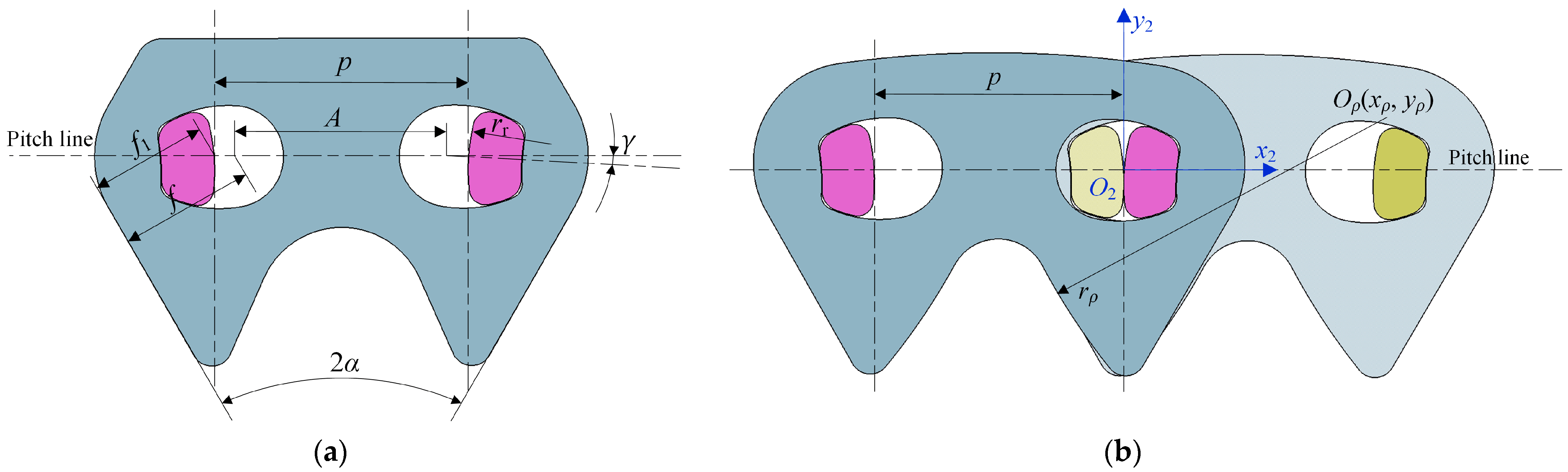
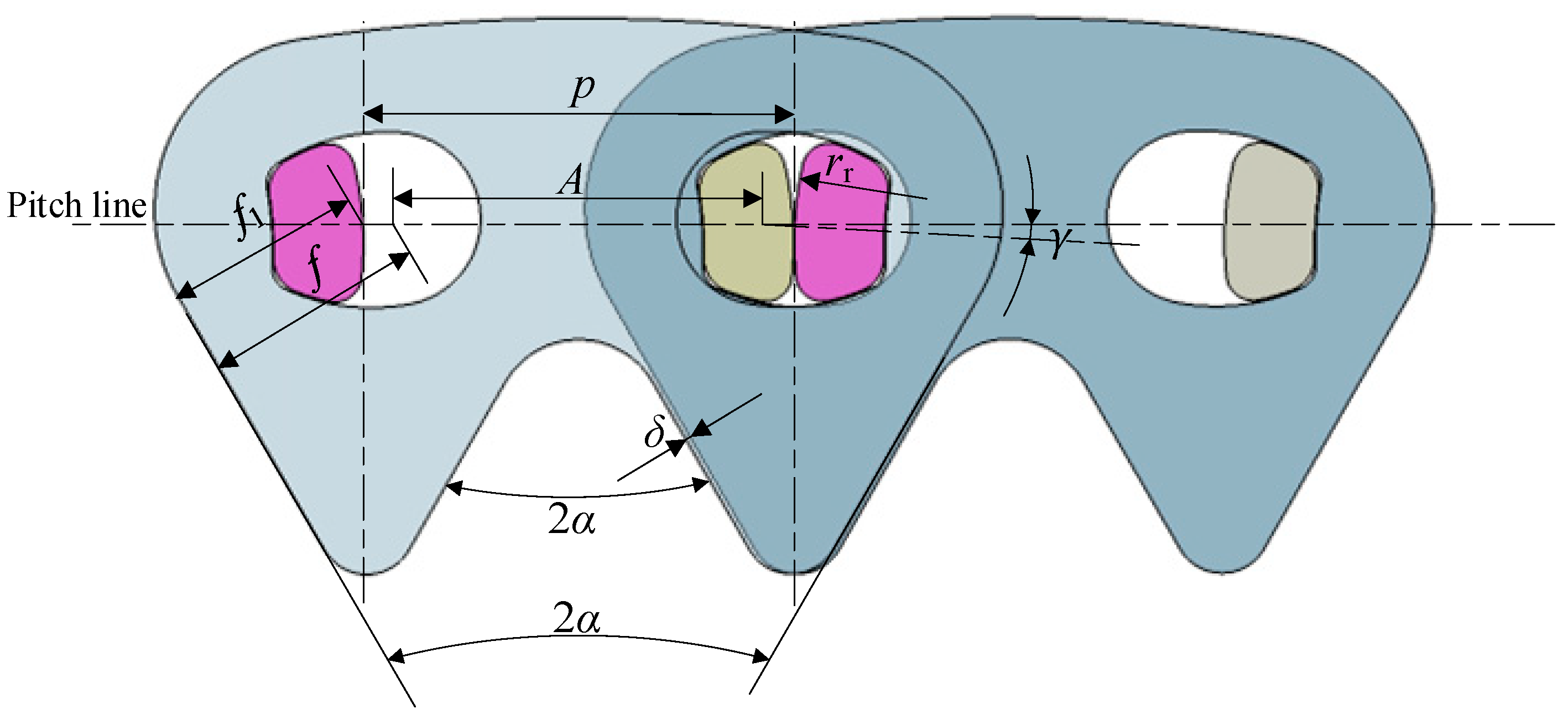
| p | The chain pitch |
| A | The hole pitch |
| α | The half angle of chain plate tooth profile |
| f | The standard apothem |
| f1 | The equivalent apothem when chain is straightened |
| γ | The positioning offsetting angle |
| rr | The contact radius of rocker pin |
| Classes | Parameters | Meanings | Functions |
|---|---|---|---|
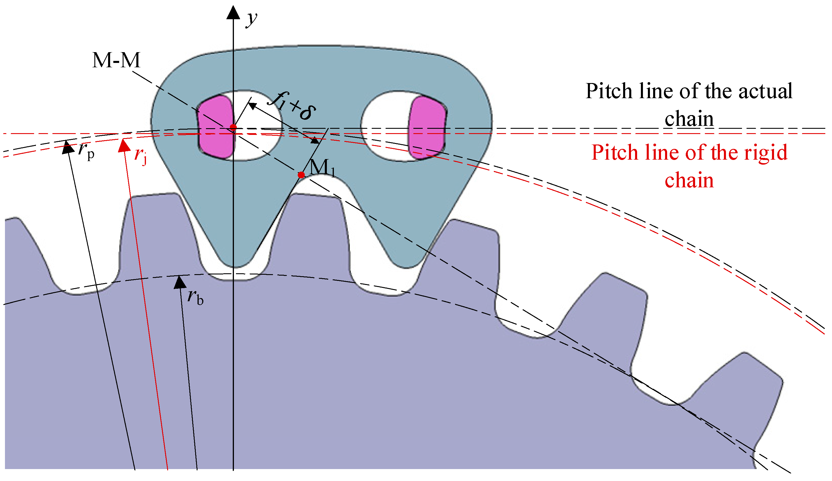
| Hy-Vo chain | pp″ | The equivalent positioning pitch | pp″ = p + 2rr + (p − A + 2rr)·tan γ·tan (φ/2) − 2rr/cos (φ/2) |
| fp″ | The equivalent positioning apothem | fp″ = f + (A − pp″)·cos α/2 | |
| rp | The radius of the positioning circle | rp = pp″/[2sin (π/z)] | |
| Sprocket | p1 | The pitch | - |
| α1 | The pressure angle | - | |
| z | The tooth number | - | |
| φ | The pitch angle | φ = 2π/z | |
| r | The radius of reference circle | r = p1z/(2π) | |
| rb | The radius of base circle | rb = r·cos α1 | |
| ra | The radius of addendum circle | - | |
| rf | The radius of dedendum circle | - |
| No. | Meshing Mechanism | Chain Link Number | Shape of Internal Meshing Profile | δ (mm) | |
|---|---|---|---|---|---|
| External Meshing | Internal Meshing | ||||
| 1 | External meshing | 84 | 0 | - | - |
| 2 | Mixed assembly | 44 | 40 | Arc | 0.21 |
| 3 | Internal–external composite meshing | 0 | 84 | Straight line | 0.108 |
Disclaimer/Publisher’s Note: The statements, opinions and data contained in all publications are solely those of the individual author(s) and contributor(s) and not of MDPI and/or the editor(s). MDPI and/or the editor(s) disclaim responsibility for any injury to people or property resulting from any ideas, methods, instructions or products referred to in the content. |
© 2023 by the authors. Licensee MDPI, Basel, Switzerland. This article is an open access article distributed under the terms and conditions of the Creative Commons Attribution (CC BY) license (https://creativecommons.org/licenses/by/4.0/).
Share and Cite
An, L.; Li, J.; Cheng, Y.; Yu, Y.; Gu, X. Design and Analysis of Internal–External Composite Meshing Hy-Vo Chain. Appl. Sci. 2023, 13, 9581. https://doi.org/10.3390/app13179581
An L, Li J, Cheng Y, Yu Y, Gu X. Design and Analysis of Internal–External Composite Meshing Hy-Vo Chain. Applied Sciences. 2023; 13(17):9581. https://doi.org/10.3390/app13179581
Chicago/Turabian StyleAn, Lichi, Jiabao Li, Yabing Cheng, Yongkang Yu, and Xingchen Gu. 2023. "Design and Analysis of Internal–External Composite Meshing Hy-Vo Chain" Applied Sciences 13, no. 17: 9581. https://doi.org/10.3390/app13179581