Article

Improved Technology for Rounding Graphite: Machine Structure and Industrial Test

1
Key Laboratory of Solid Waste Treatment and Resource Recycle, Ministry of Education, School of Environment and Resource, Sichuan Provincial Engineering Laboratory of Non-Metallic Mineral Powder Modification and High-Value Utilization, Southwest University of Science and Technology, Mianyang 621010, China
2
School of Mathematics and Physics, Southwest University of Science and Technology, Mianyang 621010, China
*
Author to whom correspondence should be addressed.
Appl. Sci. 2023, 13(17), 9820; https://doi.org/10.3390/app13179820
Submission received: 8 August 2023 / Revised: 25 August 2023 / Accepted: 29 August 2023 / Published: 30 August 2023

Abstract

:
The graphite, which is treated to be potato-shaped, is widely applied in Li-ion batteries as the anodic material. Sequential batch shaping is the main method at present. However, the small height of the shaping cavity of the existing structure leads to the problem of low processing capacity and high cost. In this work, a new structure of the shaping machine was developed with the aim of shaping graphite by large output and costless. The equipment system for graphite rounding in a pilot scale at a treatment amount of 25 kg raw material each run was established. The results showed that the ratio of the diameters of the final product by an undersized percentage corresponding to 10% was 11.15 μm, 50% was 18.94 μm, and 90% was 29.54 μm, and tap density was 0.945 g/cm3, the yield reached 48%, under the optimized conditions of 1833 rpm rotating speed of shaping disk, 2646 rpm rotating speed of classifier, and 40 min shaping period. All the above characteristics of the rounded graphite are in line with the requirements for applying in the anode of Li-ion batteries. In short, the present study aims to provide a new structure of the shaping machine, contributing to the efficient and cost-effective rounding of graphite and revealing the structure of the shaping machine, contributing to promoting the wide improvement of the shaping machine.

1. Introduction

The lithium-ion battery has become an indispensable electrochemical energy storage device in people’s lives and production activities [1]. Especially with the dramatic increasing development of the electric vehicle industry, the global demand for lithium-ion batteries is rising sharply [2]. Improving the performance and safety, as well as reducing the manufacturing cost of lithium-ion batteries, have long been the goal of the sustainable energy industry [3]. Up to now, many kinds of materials, mainly including LiMxO2 (M is one of or a combination of Co, Mn and Ni) and LiMxPO4 (M = Fe, Mn), have been developed as the cathode material to satisfy different requirements [4,5]. It is worth mentioning that, for all of the above cathode materials, graphite is their common anode material, which plays an important role in the performance and manufacturing cost of lithium-ion batteries [6].
Natural graphite occupies an important position in the anode material market due to its advantages of low cost, wide resource distribution, easy obtaining and suitable charge-discharge characteristics, and its usage is expected to grow continuously in the future [7]. The raw material for the preparation of graphite anode is usually in a flaky shape, which cannot be used directly in lithium-ion batteries [8]. Spheroidization is generally an essential process to obtain anode-active materials from the raw material of graphite in prior art processes [9], which affects many important characteristics impacting the electrochemical performance, such as the shape, tap density and particle size distribution of graphite products [10].
Excellent processing technology is the key to cost-effectively and efficiently obtaining high-quality graphite anode products from the raw material of natural graphite [11]. However, there are a few kinds of literature that have been reported focusing on graphite rounding, which is dominantly limited to the approach and a lab scale [11]. For an industrial production scale in practice, the research on equipment design and key structure improvement is still lacking.
In general, there are two main methods for particle surface modification treatment: jet milling and rotational impact blending. Jet milling is also employed in rounding treatment. In this process, the particles that need to be rounded are drafted by the high-speed airflow jetted by the nozzles. The particles are rounded via the actions of collision and grinding each other. This method is mainly used in the morphology modification of materials with high hardness, such as diamond, silicon carbide, etc., The processing cost is high, and graphite, which has high toughness, is suitable for mechanical shaping equipment. The rotational impact blending mainly uses the impact and shear of the hammer on the particles to achieve the surface modification of the particles. This method is popularly adopted for spheroidization of graphite, which is also the method adopted in this study. This method is more suitable for surface modification of graphite, a material particle with high toughness, and has the advantages of high yield and low energy consumption.
At present, the rotational impact blending for spheroidization of graphite mainly contains two ways: continuous method and intermittent method [12]. The continuous shaping machine has many advantages, but it also has the problem that the shaping time is not easy to control. However, shaping time is one of the most important factors in the final product morphology control. Batch shaping equipment is, therefore, more and more popular, and it is also the main equipment used in production. Through practical experience, we found that, at present, the intermittent shaping machine most worth improving is the increase of the output of a single machine, which is directly related to the decline of production costs. This is because the shaping machine must be equipped with other equipment, such as a turbine air classifier, dust collector, induced draft fan, etc., to form a complete equipment system to be used in production. If the production of a single shaping machine is increased without changing other supporting equipment, it means that the cost consumed in the shaping process per unit of graphite products will be greatly reduced.
There are few literatures focused on the graphite rounding process currently. M.Y. et al., proposed an improved production process with a new spheroidization machine with high efficiency and low energy consumption for rounding natural graphite for Li-battery applications [13]. The study mainly focused on the introduction of the technical craft, the influence of the process parameters on particle morphology, tap density, specific surface area, etc. This study also proved that the new process proposed has advantages and improvements in the specific energy consumption and yield compared with the traditional technology. However, the realization method, i.e., the equipment used, was not discussed. Simultaneously, there are a large number of studies focusing on the effect of sphericity parameters on the electrochemical properties of graphite materials [14,15,16,17].
On the one hand, the ultimate purpose of spherification of graphite is to improve its electrochemical performance; the most direct means of expression is to assemble the treated material into a lithium-ion battery for electrochemical performance detection, such as specific capacity, rate capability, cycling stability, etc. On the other hand, a large number of studies have confirmed that the electrochemical properties of graphite materials can be significantly improved by treating graphite with spheroids [9]. Spheroidal graphite has a smaller specific surface area and higher tap density. Thus, it has higher first-coulomb efficiency, higher reversible charge–discharge capacity and better cyclic stability [10]. Due to the above reasons, in actual production applications, physical characteristics, such as particle size distribution and tap density, are commonly used to indirectly express the electrochemical performance of materials, which has become the basis for judging whether spherical graphite products meet the application needs, which is also the actual rules of the upstream and downstream industries of the industry. Thereby, particle size distribution and tap density of the spherical graphite are selected as indicators to judge the effect of spherifying graphite.
On the basis of the above analysis, the present work focuses on the study of graphite spheroidization equipment, including the influence of equipment structure, main control parameters (including rotating speed of shaping disk, shaping period and rotating speed of classifier) on the spheroidization effect of graphite, and industrial test. The objective of this work is to provide more ideas contributing to the improvement of the structure of the shaping machine for graphite and to reveal more details about the structure and working principle of the shaping machine, which is also aimed to promote the development of this field. Specifically, a new structure of the shaping machine was developed with the aim of shaping graphite by large output and costing less. The equipment system in a pilot scale for graphite rounding was established. Key technological parameters were determined in the process of graphite shaping. This technology points out an economical and efficient way of rounding graphite.

2. Materials and Methods
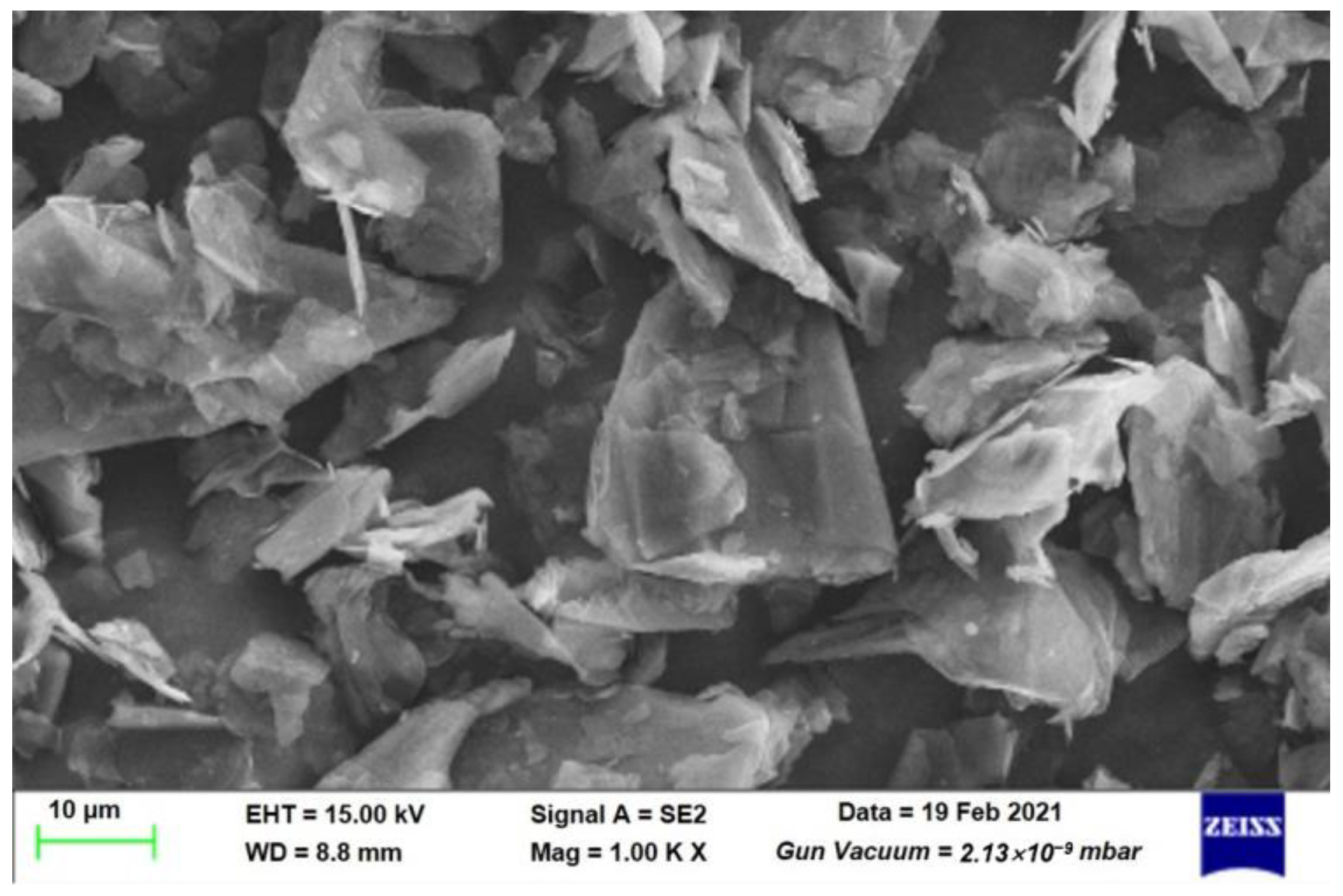
2.1. Materials

The raw material used in this study is natural flake graphite. The main characteristics of the raw material are as follows: tap density is 4.53 g/cm3, the ratio of the diameters corresponding to 10% (D10) is 5.5 μm, the ratio of the diameters corresponding to 50% (D50) is 19.0 μm, the ratio of the diameters corresponding to 90% (D90) is 37.9 μm. The scanning electron microscopy (SEM) of the raw material is shown in Figure 1.

2.2. Structure of Rounding Machine for Graphite

The structure of the proposed rounding machine for graphite is shown in Figure 2a. In general, the proposed rounding machine contains two main parts: the shaper and the classifier. The shaper consists of a shaper motor, gear ring, shaping disk and shaping frame. The classifier dominantly consists of a classifier motor and turbine rotor. The main difference between the proposed structure and the existing structure of prior art is the shaping frame, which is innovatively proposed in this study in order to increase the output of a single machine. By increasing the shaping cavity, the volume of the shaping cavity is increased to accommodate more single feed. However, under the original structure, the colliding frequency between the particles and the shaping disk will decrease, thus making the shaping effect worse. By additionally fixing a shaping frame upon and rotating with the shaping disk, the particles in the shaping cavity are simultaneously shaped by the shaping disk and the shaping frame, increasing the collision frequency and significantly improving the shaping effect. Through the above simple and low-cost improvement of the existing structure, the output of a single shaping machine can be greatly increased, and the cost consumed in the shaping process can be significantly reduced. According to the above design, the new rounding machine has been manufactured, as shown in Figure 2b.

2.3. Working Mechanism of the Proposed Rounding Machine

During the operation process, as shown in Figure 2a, the airflow enters the rounding machine via the air inlet. After that, the airflow through the gap between the shaping disk and the gear ring forms a high-speed airflow into the shaping chamber. Then, the raw material of the graphite, which needs to be shaped, enters the rounding machine through the inlet. On the one hand, once the raw material enters the shaping cavity, it will be in a high-speed rotating state immediately driven by the high-speed rotating shaping disk and be shaped by frequently colliding with the shaping disk. The shaping frame, which is set upon the shaping disk, provides more colliding opportunities for the raw material of graphite with the shaping frame. On the other hand, the graphite inside the shaping chamber is also subjected to the action of the airflow field, leading the graphite to enter the classifying area. The fine particles that do not meet the product requirement of size go out across through the classifier and are collected by a dust collector as a by-product, while the graphite whose size meets the requirement of the product cannot go across through the classifier and are back to the rounding area driven by the airflow to be shaped again until the processing is finished. During the above process, the irregular and sharp edges of the graphite particles are polished and rounded into potato-like granules to achieve the purpose of spherification. The precise control of the classification process can effectively reduce or even avoid the occurrence of over-crushing, contributing to significantly improving the yield of products. When processing is complete, the finished product outlet valve is opened, and the finished product goes into the finished product collector for collection. The dominant difference between the proposed structure and the current rounding machine is that the set of the shaping frame, which directly leads to the presented structure of the shaping chamber, is much higher. On the basis of the above principle, the aim of the set of the shaping frame is to increase the production ability of the rounding machine.

2.4. Graphite Rounding System

On the basis of the above studies, an efficient and controllable rounding system for graphite was designed and established, as shown in Figure 3. The system mainly contains four parts: the rounding machine accompanied by the turbine air classifier, final product collector, high-efficiency filter cylinder dust collector, and high-pressure induced draft fan. The raw material is entered into the rounding machine via the star feeder. In the rounding process, fine particles will be removed from the shaping chamber by the action of the classifier and collected by the filter cylinder dust collector to improve the quality of the final product and its yield. Simultaneously, the other particles whose size meets the product requirement are modified by the action of shaping the disk and shaping the frame for a certain period (5~60 min) until the rounding treatment is finished. Then, the rounding machine is turned off, and the final product outlet valve is opened. The final product in the shaping chamber enters into the final product collector by the action of the airflow provided by the high-pressure induced draft fan and is collected.
For each run, the rotating speed of the shaping disk, shaping period, and rotating speed of the classifier were first set through the screen of the programmable logic controller (PLC). Secondly, turned on the classifier, induced draft fan and shaping machine in turn. At this time, the final product outlet was closed. Thirdly, 25 kg of raw material was fed into the feeder. Fourthly, the value is by clicking the corresponding button on the screen of the PLC, and the raw material is entered into the shaping machine. Finally, After the shaping process is completed and the product is discharged, the sample is uniformly collected for testing particle size distribution and vibration density.

2.5. Investigation of Parameters for Graphite Rounding

For each test, 25 kg of raw material was fed into the rounding machine via the star feeder. Then, the rounding machine was turned on to start shaping and maintained for a certain period. Next, open the outlet value for the product and close the outlet value for the fine particles. The final product was transported by the airflow and entered into the final product collector, as shown in Figure 3.
Effects of shaping period, rotating speed of shaping disk, and rotating speed of classifier on diameter distribution, tap density, and yield of the final product were investigated. To establish the effect of shaping periods ranging from 30 to 80 min in increments of 10 min, the rotating speeds of the shaping disk and classifier were set at 1833 and 2646 rpm, respectively. To determine the effect of the rotating speed of the shaping disk of 1100, 1283, 1467, 1650, and 1833 rpm, the shaping period and rotating speed of the classifier were set at 40 min and 2646 rpm, respectively. To determine the effect of the rotating speed of the classifier, the shaping period and the rotating speed of the classifier were set at 40 min and 1833 rpm, respectively. After each experiment was completed, the equipment was turned off. All fine particles were collected by the high-efficiency filter cylinder dust collector, and all final product was collected by the final product collector.

2.6. Characterization Methods

The performance of the test was characterized by the diameter distribution represented by D10, D50, and D90, tap density, and final product yield (as shown in Equation (1)). The diameter distribution of the graphite particle was detected by the laser diffraction particle size analyzer (Mastersizer 3000, Malvern Panalytical, Malvern, UK). The degree of sphericity of the graphite particle was detected by the particle shape analyzer (Morphologi G3, Malvern, UK). The tap density was determined by a tap density analyzer (BT-301, Bettersize, Dandong, China). Scanning electron microscopy (SEM, SUPRA 55, Zeiss, Jena, Germany) was used to observe the morphology of particles. The raw materials and the final product were measured by an electronic balance with a resolution 1 g.
Y i e l d % = m a s s   o f   t h e   f i n a l   p r o d u c t   ( k g ) m a s s   o f   t h e   r a w   m a t e r i a l   ( 25   k g ) × 100 %

3. Results and Discussion

3.1. Rounding Effect

3.1.1. Effect of the Rotating Speed of Shaping Disk on Graphite Rounding

The rotating speed of the shaping disk is the most important factor impacting on shaping strength. Excessive rotating speed will lead to pulverization of the particles, while too low rotating speed cannot provide enough strength to wear away the irregular corners of the particles. For different kinds of graphite, the appropriate rotating speed of shaping the disk should be determined according to the specific material characteristics (such as hardness). The present results reveal the influence law of parameters and the performance of the shaping machine proposed.
Figure 4 shows the effect of the rotating speed of the shaping disk on the rounding performance of the graphite used in this study when the shaping period and the rotating speed of the classifier were kept at 40 min and 2646 rpm, respectively. With the increase of the rotating speed of the shaping disk from 1100 to 1833 rpm, especially from 1100 to 1467 rpm, the particle diameters, including D10, D50 and D90, are affected slightly. Specifically, when the rotating speed of the shaping disk increases from 1467 to 1833 rpm, D10 increases from 9.83 to 11.15 μm while D90 decreases from 31.02 to 29.54 μm. This phenomenon indicates that with the increase in the rotating speed of the shaping disk, the action of shaping is strengthened. The size of large particles decreases slightly when their irregular edges are worn away, contributing to the decrease of D90. For small particles, after their surface is more abraded off, their particle size becomes smaller, which is easier to capture by the classifier as fine particles are discharged from the shaping cavity. That is why D10 slightly increases as the rotating speed of the shaping disk goes from 1467 to 1833 rpm.
The higher the shaping strength, the greater the amount of fine particles produced and discharged and the lower the yield. On the contrary, high shaping strength leads to higher abrasion degrees of irregular edges and corners of particles and, thus, higher tap density. It is worth emphasizing that the effect of the rotating speed of the shaping disk below 1467 rpm on the tap density is very small, which means that the shaping strength is insufficient at this time. When the rotating speed of the shaping disk increases from 1467 to 1650 rpm, the tap density increases sharply from 0.85 to 0.912 g/cm3. Successively increasing the rotating speed of the shaping disk to 1833 rpm, the tap density continuously increases to 0.945 g/cm3, indicating that when the rotating speed of the shaping disk is 1467 rpm, the particles begin to suffer an obvious shaping effect. When the rotating speed reaches 1833, the shaping effect has been relatively strong. If the rotating speed continues to increase, the crushing effect may be triggered.

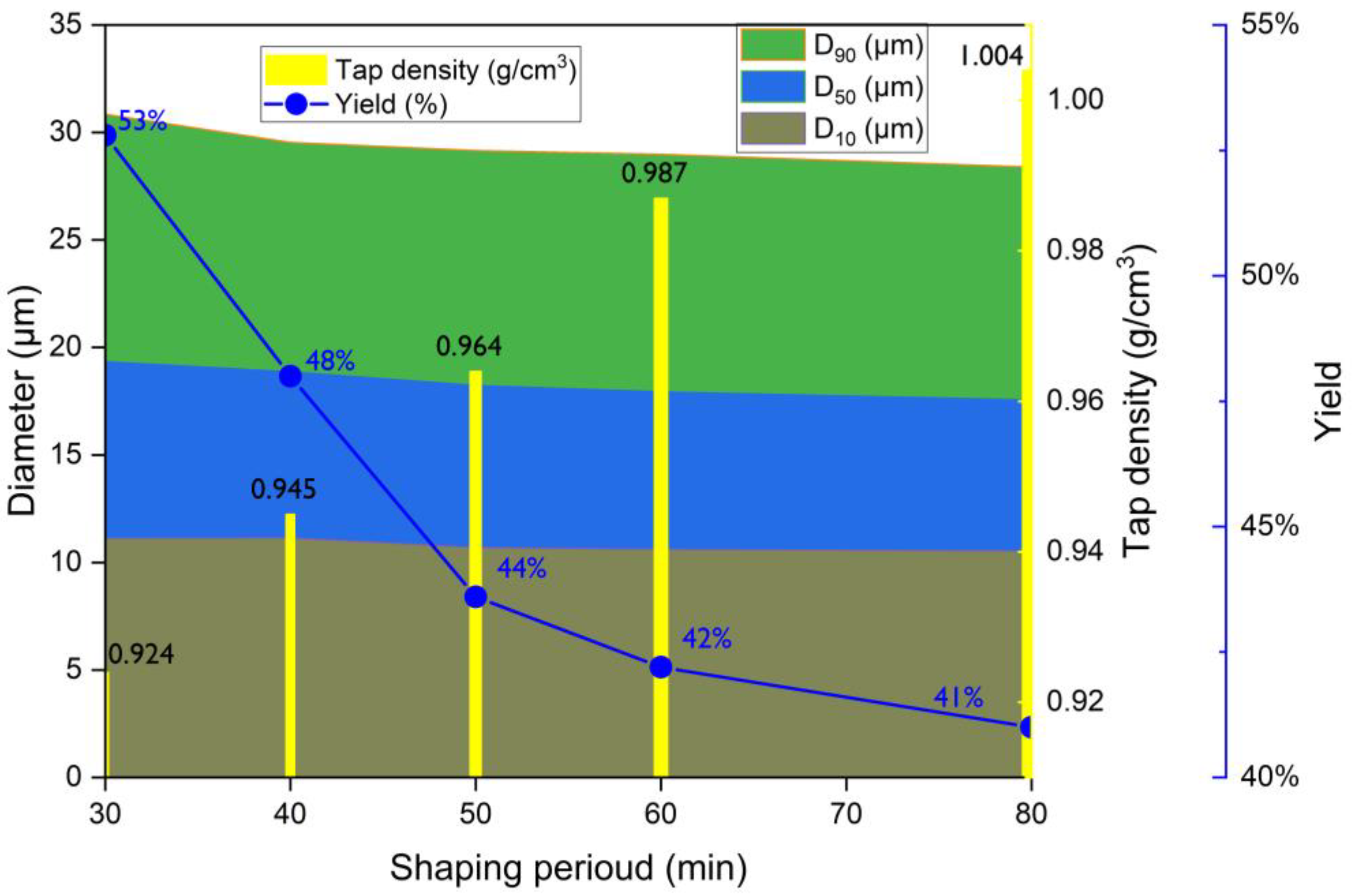
3.1.2. Effect of the Shaping Period on Graphite Rounding

The determination of reasonable shaping strength is mainly to ensure that the particles are mainly subjected to shaping action rather than crushing. Under the setting condition, the shaping time mainly affects the shaping degree and yield of the final product. Figure 5 shows the effect of the shaping period on the graphite rounding performance when the rotating speed of the shaping disk was kept at 1833 rpm, and the rotating speed of the classifier was limited to 2646 rpm. It is observed that the diameters, including D10, D50 and D90, all change negligibly with a slight decrease with the shaping period increases. For example, with the shaping period increases from 30 to 80 min, D10 decreases from 11.12 to 10.54 μm, D50 decreases from 19.41 to 17.63 μm, and D90 decreases from 30.85 to 28.39 μm. It indicates that under the present conditions, the graphite particles inside the rounding process are dominantly subjected to be shaped rather than pulverized. Although the diameter changes negligibly, the tap density increases dramatically from 0.924 to 1.004 g/cm3 while the yield declined sharply from 53 to 41% with the increase of the shaping period from 30 to 80 min. The dramatic increase in tap density clearly points out that the irregular corners of the graphite particles are constantly worn away and form fine particles. The formed fine particles are captured by the classifier and collected by the dust collector. This is also the reason that leads to the decline of the final product yield. The diameter and tap density are the main factors influencing the product quality, and the yield is the main factor impacting the cost. The specific parameter selection should be based on the performance and application requirements of the final product while taking into account the principle of cost-effectiveness.

3.1.3. Effect of the Rotating Speed of Classifier on Graphite Rounding

Different from shaping time and shaping strength, the rotating speed of the classifier has no direct effect on particle shaping but indirectly influences the characteristics of the final product by capturing and discharging particles. Figure 6 shows the effect of the rotating speed of the classifier on the graphite rounding performance, when the rotating speed of the shaping disk was kept at 1833 rpm and the shaping period was limited to 40 min. Firstly, there is a trend that the yield increases dramatically, with the increase of the rotating speed of the classifier, while diameters containing D10, D50 and D90 all decrease obviously. On the one hand, according to the working principle of the classifier, under the condition of constant air volume, the cutting particle size decreases with the increase of the classifier speed, which means that the number of particles captured by the classifier decreases and the number of particles remaining in the classification chamber as finished products increases [18,19]. On the other hand, the particle with a larger diameter has greater inertia force, and the spheroidization intensity is higher, which makes D90 decrease significantly, and the particle size distribution of the finished product is more concentrated. The rotating speed of the classifier has a slight effect on the tap density of the final product, but there is no obvious rule. When the rotating speed of the classifier increases from 2058 to 2646 rpm, the tap density only varies from 0.937 to 0.949 g/cm3, with a small range of 0.012 g/cm3. It can be obviously concluded that the rotating speed of the classifier has no direct effect on the tap density but indirectly affects the particle size distribution of the finished product. More directly, the rotating speed of the classifier has an effect on the particle size distribution of the finished product, and the particle size distribution has an effect on the tap density. Therefore, the rotating speed of the classifier should be determined according to the demand for yield and finished particle size distribution.

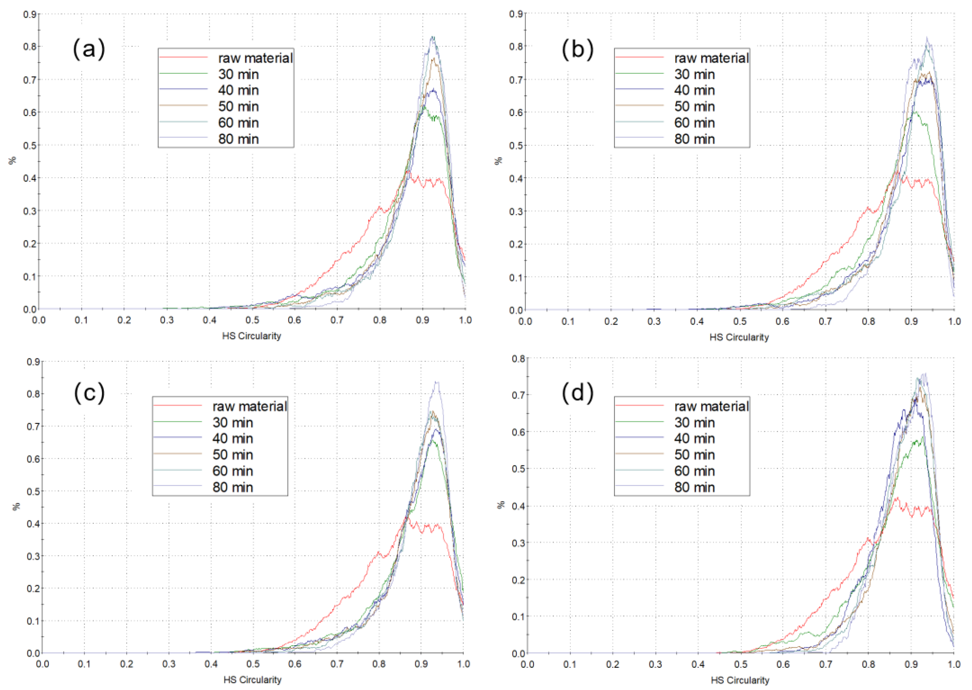
3.1.4. Discussion on Degree of Sphericity of Graphite Particle Impacted by Shaping Period and Shaping Disk Rotating Speed

Figure 7a shows the degree of sphericity of graphite particles of raw material and shaped treated for 30, 40, 50, 60, and 80 min at a shaping disk rotating speed of 1283 rpm. Figure 7b shows the degree of sphericity of graphite particles of raw material and shaped treated for 30, 40, 50, 60, and 80 min at a shaping disk rotating speed of 1467 rpm. Figure 7c shows the degree of sphericity of graphite particles of raw material and shaped treated for 30, 40, 50, 60, and 80 min at a shaping disk rotating speed of 1650 rpm. Figure 7d shows the degree of sphericity of graphite particles of raw material and shaped treated for 30, 40, 50, 60, and 80 min at a shaping disk rotating speed of 1833 rpm. It is obvious from Figure 7a–d that (1) the degree of sphericity of graphite particle increased slightly with the increase of shaping disk rotating speed from 1283 to 1833 rpm; (2) under different rotating speed conditions, the sphericity increased with the extension of shaping time, and when the shaping time reached 40 min, the increasing rate of sphericity slowed down and gradually became stable. From the aspects of yield, energy consumption and product quality, 1833 rpm and 40 min are also suitable conditions for graphite rounding.

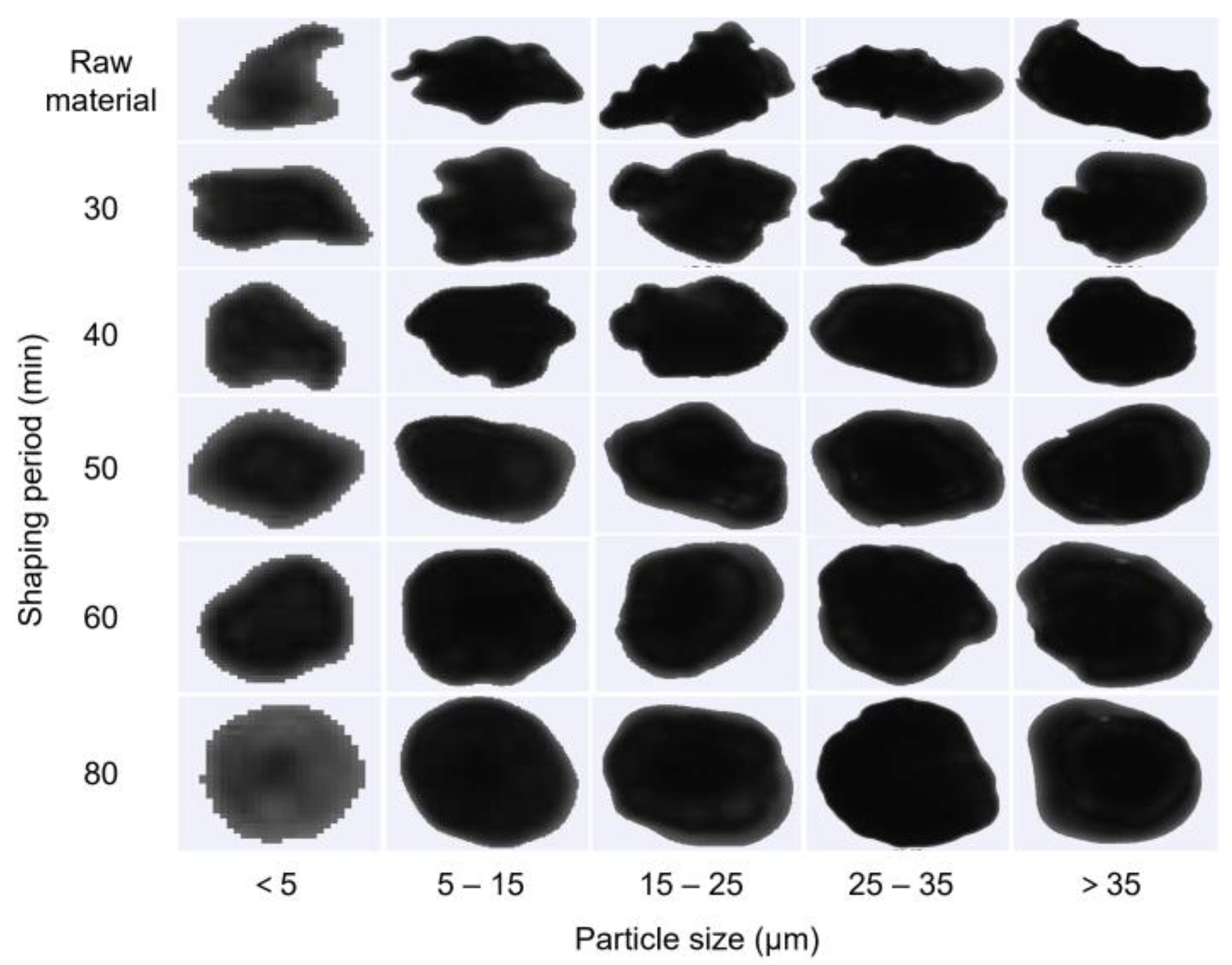
3.1.5. Discussion on Shape of Graphite Particle Impacted by Shaping Period

Raw material and spherical graphite obtained from different spheroidization treatment times (including 30, 40, 50, 60 and 80 min) are divided into five particle size segments, which are >5, 5–15, 15–25, 25–35, and >35 μm, respectively, to clearly and visually show the shape changes of graphite particles during spheroidization treatment, as shown in Figure 8. Three conclusions could be concluded: (1) the spheroidization time is the same, and the shape of different grades is similar; (2) for all particle sizes, the shape of the same particle size tends to be more spherical with the extension of spherification treatment time; (3) for all particle grades, the graphite particles reached potato shape (without sharp edges) when the spherification treatment time reached 40 min.

3.2. Optimized Test

The above investigations indicate that 1833 rpm of the rotating speed of the shaping disk, 40 min of the shaping period, and 2646 of the rotating speed of the classifier are reasonable and suitable conditions for good performance of rounding for the graphite employed in this study. Under the above-optimized condition, the diameter distribution of the final product is shown in Figure 9a, D10 is 11.15 μm, D50 is 18.94 μm, and D90 is 29.54 μm. The yield is 48%. The tap density is 0.945 g/cm3. Figure 9b,c show that there are no irregular and sharp edges on the graphite shaping product particles, which are potato-like shapes with good sphericity.

4. Conclusions

This study provided an improved structure of the graphite rounding machine, which can be realized by a low-cost and simple operation. Compared with the existing technology, a shaping frame was additionally fixed upon and rotating with the shaping disk in the proposed structure to increase the output of a single shaping machine and decrease the cost consumed in the shaping process. The important parameters impacting the rounding performance of graphite were investigated. The rotating speed of the shaping disk of 1833 rpm, the shaping period of 40 min, and the rotating speed of the classifier of 2646 rpm were determined as reasonable conditions. The D10 of the final product was 11.15 μm, D50 was 18.94 μm, and D90 was 29.54 μm, tap density was 0.945 g/cm3, and the yield reached 48%, by the established graphite rounding system in a pilot-scale at a treatment amount of 25 kg raw material for each run. All the above characteristics of the rounded graphite are in line with the application requirements of graphite anode materials. The improved structure of the shaping machine, the established equipment system, and the parameters obtained in this study can be directly used in production so as to reduce the cost of the present graphite spheroidization process. The above results provide reference and data support for the application and further study of improvement in the technology of graphite rounding.

Author Contributions

Conceptualization, J.C., M.Z. and H.C.; methodology, J.C. and L.L.; validation, X.L. and T.M.; formal analysis, Y.L. and C.Y.; investigation, J.C.; resources, H.C.; data curation, J.W.; writing—original draft preparation, J.C. and T.M.; writing—review and editing, J.W. and Y.L.; visualization, Y.L.; supervision, H.C.; project administration, J.C. All authors have read and agreed to the published version of the manuscript.

Funding

This research received no external funding.

Institutional Review Board Statement

Not applicable.

Informed Consent Statement

Not applicable.

Data Availability Statement

Not applicable.

Acknowledgments

We thank the Analytical and Testing Center of Southwest University of Science and Technology for providing experimental measurements, and Yang worked in Mianyang Liu Neng Powder Equipment Co., Ltd., who contributed to the investigation.

Conflicts of Interest

The authors declare no conflict of interest.

References

  1. Zhao, F.; Zhao, M.; Dong, Y.; Ma, L.; Zhang, Y.; Niu, S.; Wei, L. Facile preparation of micron-sized silicon-graphite-carbon composite as anode material for high-performance lithium-ion batteries. Powder Technol. 2022, 404, 117455. [Google Scholar] [CrossRef]
  2. Sun, H.; Song, Q.; Xu, Z. A method for using the residual energy in waste Li-ion batteries by regulating poential with the aid of overvoltage response. Proc. Natl. Acad. Sci. USA 2023, 120, e2213130120. [Google Scholar] [CrossRef] [PubMed]
  3. Han, L.; Zhu, X.; Yang, F.; Liu, Q.; Jia, X. Eco-conversion of coal into a nonporous graphite for high-performance anodes of lithium-ion batteries. Powder Technol. 2021, 382, 40–47. [Google Scholar] [CrossRef]
  4. Xiao, J.; Li, J.; Xu, Z. Challenges to future development of spent lithium ion batteries recovery from environmental and technological perspectives. Environ. Sci. Technol. 2020, 54, 9–25. [Google Scholar] [CrossRef] [PubMed]
  5. Lin, N.; Jia, Z.; Wang, Z.; Zhao, H.; Ai, G.; Song, X.; Bai, Y.; Battaglia, V.; Sun, C.; Qiao, J.; et al. Understanding the crack formation of graphite particles in cycled commercial lithium-ion batteries by focused ion beam—Scanning electron microscopy. J. Power Sources 2017, 365, 235–239. [Google Scholar] [CrossRef]
  6. Vanderbruggen, A.; Sygusch, J.; Rudolph, M.; Serna-Guerrero, R. A contribution to understanding the flotation behavior of lithium metal oxides and spheroidized graphite for lithium-ion battery recycling. Colloid. Surf. A 2021, 626, 127111. [Google Scholar] [CrossRef]
  7. Biber, B.; Sander, S.; Martin, J.; Wohlfahrt-Mehrens, M.; Mancini, M. Improved production process with new spheroidization machine with high effciency and low energy consumption for rounding natural graphite for Li-ion battery applications. Carbon 2023, 201, 847–855. [Google Scholar] [CrossRef]
  8. Mundszinger, M.; Farsi, S.; Rapp, M.; Golla-Schindler, U.; Kaiser, U.; Wachtler, M. Morphology and texture of spheroidized natural and synthetic graphites. Carbon 2017, 111, 764–773. [Google Scholar] [CrossRef]
  9. Wu, Y.S.; Yeh, T.S.; Lee, Y.H.; Lee, Y.C. Spheroidization modification of artificial graphite applied as anode materials for high rate lithium ion batteries. Adv. Mater. Res. 2011, 201–203, 421–424. [Google Scholar] [CrossRef]
  10. Mancini, M.; Martin, J.; Ruggeri, I.; Drewett, N.; Axmann, P.; Wohlfahrt-Mehrens, M. Enabling fast-charging lithium-ion battery anodes: Influence of spheroidization on natural graphite. Batter. Supercaps 2022, 5, e202200109. [Google Scholar] [CrossRef]
  11. Teng, D.L.; Li, P.; Yuan, N.; Lv, J.; Chen, J.D.; Lin, L.Y.; Chen, H.Y. Process parameters optimization of natural graphite spheroidization. China Powder Sci. Technol. 2021, 27, 70–76. (In Chinese) [Google Scholar]
  12. Peng, H.E.; Zhang, Z.; Xiao, X. Application and prospect of natural graphite spheroidization equipment. China Non-Met. Miner. Ind. 2020, 4, 6–9. (In Chinese) [Google Scholar]
  13. Yoshio, M.; Wang, H.; Fukuda, K.; Umeno, T.; Abe, T.; Ogumi, Z. Improvement of natural graphite as a lithium-ion battery anode material from raw flake to carbon-coated sphere. J. Mater. Chem. 2004, 14, 1754–1758. [Google Scholar] [CrossRef]
  14. Park, Y.S.; Lee, T.W.; Shin, M.S.; Lim, S.H.; Lee, S.M. Modification for improving the electrochemical performance of spherically-shaped natural graphite as anode material for lithium-ion batteries. J. Electrochem. Soc. 2016, 163, A3078–A3086. [Google Scholar] [CrossRef]
  15. Prakash, S.; Kumar, R.; Gupta, A.; Chaudhary, A.; Chandaliya, V.K.; Dash, P.S.; Gurunathan, P.; Ramesha, K.; Kumari, S.; Dhakate, S.R. A process for developing spherical graphite from coal tar as high performing carbon anode for Li-ion batteries. Mater. Chem. Phys. 2022, 281, 281. [Google Scholar] [CrossRef]
  16. Shi, M.; Tai, Z.; Li, N.; Zou, K.; Chen, Y.; Sun, J.; Liu, Y. Spherical graphite produced from waste semi-coke with enhanced properties as an anode material for Li-ion batteries. Sustain. Energy Fuels 2019, 3, 3116–3127. [Google Scholar] [CrossRef]
  17. Fischer, S.; Doose, S.; Müller, J.; Höfels, C.; Kwade, A. Impact of Spheroidization of Natural Graphite on Fast-Charging Capability of Anodes for LIB. Batteries 2023, 9, 305. [Google Scholar] [CrossRef]
  18. Ohzeki, K.; Saito, Y.; Golman, B.; Shinohara, K. Shape modification of graphite particles by rotational impact blending. Carbon 2005, 43, 1673–1679. [Google Scholar] [CrossRef]
  19. Huang, Q.; Liu, J.; Yu, Y. Turbo air classifier guide vane improvement and inner flow field numerical simulation. Powder Technol. 2012, 226, 10–15. [Google Scholar] [CrossRef]
Figure 1. Scanning electron microscopy (SEM) of the raw material used in this study.
Applsci 13 09820 g001
Figure 2. Structure (a) and photo (b) of the proposed rounding machine for graphite. (01: classifier motor; 02: turbine rotor; 03: shaping disk; 04: shaping frame; 05: gear ring; 06: shaper motor).
Applsci 13 09820 g002
Figure 3. Structure of graphite rounding system.
Applsci 13 09820 g003
Figure 4. Effect of the rotating speed of shaping disk on the graphite rounding performance.
Applsci 13 09820 g004
Figure 5. Effect of the shaping period on the graphite rounding performance.
Applsci 13 09820 g005
Figure 6. Effect of the rotating speed of the classifier on the graphite rounding performance.
Applsci 13 09820 g006
Figure 7. Degree of sphericity of graphite particle for different shaping periods at shaping disk rotating speed of (a) 1283, (b) 1467, (c) 1650, and (d) 1833 rpm.
Applsci 13 09820 g007
Figure 8. The Shape of graphite particles with different size distributions impacted by the shaping period from 30 to 80 min under shaping disk rotating speed at 1833 rpm.
Applsci 13 09820 g008
Figure 9. Diameter distribution of the final rounding product of graphite (a); scanning electron microscopy (SEM) of the final rounding product of graphite by (b) 500× and (c) 2000×.
Applsci 13 09820 g009
Disclaimer/Publisher’s Note: The statements, opinions and data contained in all publications are solely those of the individual author(s) and contributor(s) and not of MDPI and/or the editor(s). MDPI and/or the editor(s) disclaim responsibility for any injury to people or property resulting from any ideas, methods, instructions or products referred to in the content.

