Abstract
A new type of grouting material—FCM (fast cementing material)—is being used in coastal and offshore infrastructure projects, such as harbor and tunnel rehabilitation. In order to investigate how this material performs under different conditions, the compressive strength, failure mode, and surface microscopic changes of different fracture penetration degrees and different crack angles of grout-reinforced specimens formed by the FCM and sandstone were investigated in an acidic environment with pH = 1.1 and after freeze–thaw cycles of 5, 10, 20, and 30 times. In addition, through the preliminary determination of FCM grouting material fluidity and setting time, it was determined that the water-material ratio in this test is 0.3, and the sandstone used has good uniformity. The results show that the strength of the original rock can be matched or even exceeded by the solid grout of FCM and sandstone. Acidic environments and freeze–thaw cycles will erode the specimens, mainly on the surface of the specimens. The fracture penetration degree and crack angle determine the degree of strength reduction of the specimens. The compressive strength of the specimens decreases most rapidly within 10 freeze–thaw cycles. After soaking in acidic solution and a freeze–thaw cycle in an acidic environment, particle shedding occurs on the surface of the grout material and a “honeycomb” area appears on the surface of the sandstone. As the freeze–thaw cycle increases, the particle-shedding area and the honeycomb area increase continuously.
1. Introduction
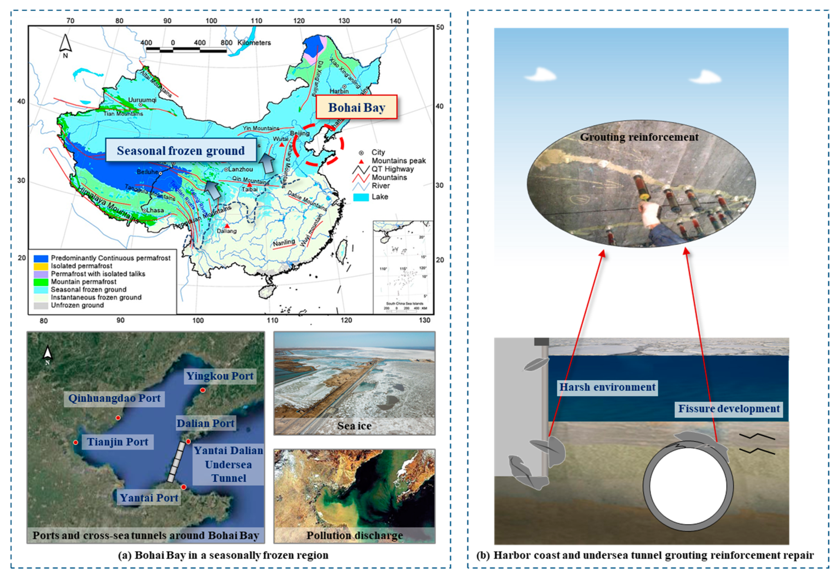
China has a vast area of frozen soil area of which permafrost accounts for about 21.5% of the total land area, and seasonal frozen soil accounts for 53.5%. It is one of the most widespread distributed countries in the world [1,2]. Bohai Sea is located between 37°~41° N and consists of Liaodong Bay, Bohai Bay, Laizhou Bay, and the central shallow sea basin. Surrounded by land on three sides, it is a semi-enclosed sea area with little heat exchange with external seawater. Under the influence of factors, such as the Siberian High and Pacific Subtropical High in winter, the freezing phenomenon is significant [3,4,5,6]. At the same time, during the period of rapid industrial development, the ecological environmental problems in some parts of the Bohai Sea have become more prominent. The proportion of stations with water quality worse than class four in the coastal waters of Liaoning and Shandong Bohai increased from 3.6% in 2016 to 16.1% in 2018 [7]. Nowadays, the cargo throughput of major ports around the Bohai Sea (Yantai Port, Tianjin Port, Yingkou Port, Dalian Port) is increasing, water transport projects are developing rapidly [8], and the construction of the Yantai undersea tunnel has been put on the agenda [9]. In the harsh environment of the Bohai Sea, these coastal and marine projects are inevitably affected (as shown in Figure 1a). There are often many cracks and pores in the deep rock mass [10]. Under the action of a long-term hydrochemical environment and a freeze–thaw cycle, the water–ice phase transformation occurs in these macro and micro defects, resulting in frost heave force, which drives the expansion of original defects and the initiation of new cracks. Eventually, joints and fractures join or break, threatening coastal and underwater engineering structures [11,12,13,14].
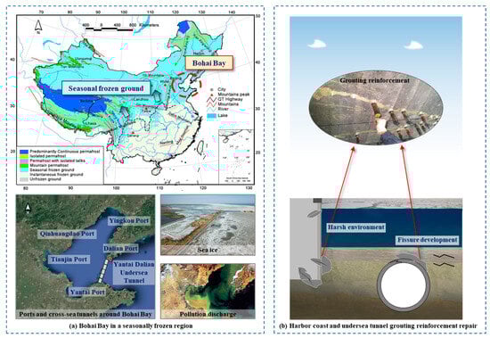
Figure 1.
Bohai Bay key project and grouting reinforcement technology.
With the increasing construction of geotechnical engineering in Bohai Bay, grouting reinforcement technology should be considered to maintain the stability of deep fractured, weak surrounding rock in these areas [15]. Grouting reinforcement technology is one of the most effective methods to solve rock fracture damage under a freeze–thaw and hydrochemical environment (as shown in Figure 1b). However, under the action of an acid water environment in a coastal seasonal frozen area, the grout-reinforced specimens will still be affected by an acid environment and a freeze–thaw cycle, and the internal structure and mechanical properties will change, which brings great hidden dangers to the stability and safety of rock mass engineering. Therefore, in order to prevent and solve the disaster problems of the grouting reinforcement projects in an acidic freeze–thaw environment and reduce unnecessary engineering waste, it is particularly important to study the mechanical properties of the grout-reinforced specimens damaged in coastal seasonal frozen areas in an acidic environment.
With the continuous development of engineering technology, research results in grouting materials, grouting technology, and diffusion mechanisms that are increasing [16,17,18,19,20]. Grouting material is the primary factor that determines the construction effect of the grouting reinforcement project. It is generally composed of base material, an external reference agent, and a solvent. After more than two centuries of development, grouting materials have evolved from ‘single grouting material’ to ‘modified grouting material’ and then to ‘composite grouting material’ to meet the requirements of different engineering needs, technical levels, and composite material development [21].
In the excavation stage of underground engineering construction, an important reason for engineering instability is the shear failure of the rock mass joint area [22,23,24,25]. In order to solve this problem, the grouting reinforcement of fractured rock mass arises at the historic moment. It can improve the mechanical structure of the fracture surface and then improve the mechanical properties of the whole rock mass to effectively prevent the instability and failure of underground engineering. At present, researchers have carried out many mechanical studies on the strength and deformation characteristics of the consolidated body after grouting. Through a series of grouting tests, Nasir et al. [26] and Tian et al. [27] found that the shear strength curve of grouting consolidation has an obvious peak and residual strength. Wang et al. [28] used chemical grout to grout fractured rock masses and found that this method can make the specimens a more complete structure. However, the strength of the grouting material and its bonding with the rock mass are important factors limiting the grouting results. Based on the study of residual strength and deformation properties of fractured rock, Zhang et al. [29] further explored the mechanical properties of grout-reinforced specimens. The research shows that after grouting consolidation, the residual strength of the broken rock block is significantly improved, and its lateral and radial changes also tend to be synergistic, which greatly improves the plastic deformation function of the broken rock block so that it can still maintain good bearing capacity in a large change range. At present, many researchers have conducted much research on rock-like specimens instead of rock as rock mechanics test materials. However, there are relatively few studies on the mechanical properties of grout-reinforced specimens prepared by real rock mass cutting and grouting. Chen [30], Wong [31], and Bobet [32] all took gypsum as the analysis object and analyzed the effect of fracture dip angle on rock hardness and deformation characteristics.
Chai et al. [33] studied the law of damage and deterioration of rock with a filling joint caused by the acid dry–wet cycle and found that there was a strong linear relationship between the static and dynamic compressive strength and the wave velocity of the filled joint rock under the action of dry and wet cycling. Zhang et al. [34] studied the evolution of microscopic pores and the shear mechanical response of fractured rock under freeze–thaw cycles and found that the freeze–thaw deterioration of the grout rock interface layer was mainly caused by the solid–liquid phase change and migration of internal water under the action of circulating temperature, and the difference of grouting materials had a great influence on the degree of freeze–thaw deterioration of the grout rock interface layer.
For the study of the physical and mechanical properties of grout-reinforced specimens, most are only based on the study of grout-reinforced specimens mechanics and grouting effect under a normal temperature environment. Some scholars have studied the damage of grout-reinforced specimens under low–temperature or single acid–base environment. There are few studies on the mechanical damage of grout-reinforced specimens under the coupling of an acid environment and a freeze–thaw cycle. In this paper, combined with the research status of grouting materials and grout-reinforced specimens and considering the existing conditions, the uniaxial compression test and scanning electron microscope microscopic imaging method were used to carry out the test of the grout-reinforced specimens erosion in an acidic environment and the test of grout-reinforced specimens performance damage under the coupling of a freeze–thaw cycle in an acidic environment.
2. Materials and Methods
2.1. Materials
The research object selected in this test is red sandstone, and through polarization experiments and X-ray diffraction (XRD) analysis, the main components of the rock include quartz, albite, gismondine, and other feldspars as well as some rock chips and cemented material. Three red sandstones were selected to study the initial physical properties, and some basic physical parameters of sandstone specimens were obtained. The test results are shown in Table 1.

Table 1.
Physical and mechanical properties of sandstone.
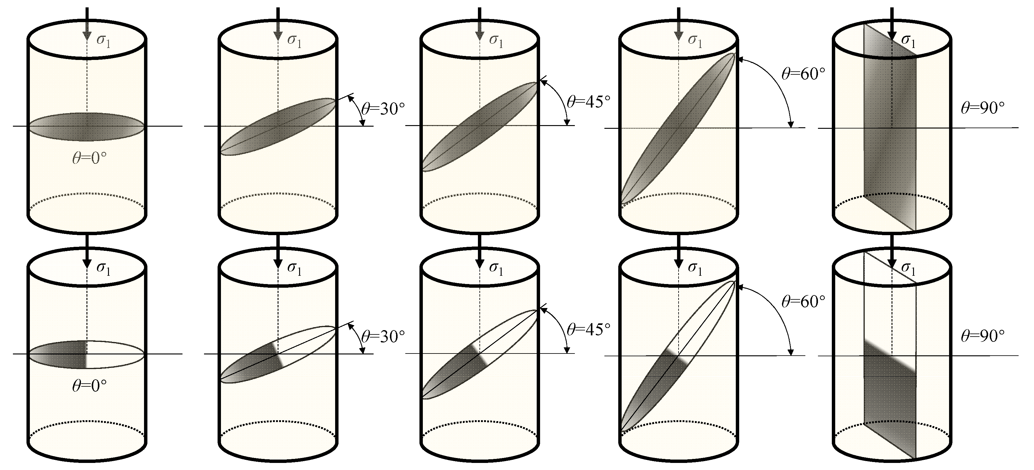
The influence of different fracture dip angles on the mechanical properties of grout-reinforced specimens was explored. According to the research of relevant scholars [35], the rock-cutting machine is used to cut the sandstone. The fracture dip angle is divided into 0° (horizontal), 30°, 45°, 60°, and 90°. The fracture penetration degree is divided into full-section penetration and half-section penetration. The prefabricated fractured sandstone is shown in Figure 2. The crack width is 2 mm.
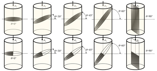
Figure 2.
Prefabricated fractured sandstone shape.
In this experiment, the commercially available new rapid cementing material (FCM) was used as grouting material. FCM is a new rapid grouting material based on sulphate aluminium cement. In order to compare the particle size of FCM and P.O 42.5 cement, a Winner 3003 Laser Particle Sizer was used to measure the particle size distribution of the two materials. The measuring range of the instrument was 0.1~1200 μm, and the average particle size of the powder was obtained. The particle size distributions of the cementitious materials are presented in Table 2. The average particle size of FCM is higher than that of P.O 42.5 cement, which is 54.225 μm for FCM and 22.733 μm for P.O 42.5 cement.
Table 2.
Particle-passing percentage of the cementitious materials/%.
In order to verify the fluidity and solidification performance of FCM at a lower water-to-material ratio, the flowability and setting time tests of FCM and P.O 42.5 under different water–solid ratios were designed. The test results are shown in Table 3 and Table 4. It can be seen from the figure that the fluidity of FCM is nearly six times that of P.O 42.5, and the setting time of FCM is one fifth of P.O 42.5 under the condition of a low water–material ratio. Therefore, FCM with a water-to-material ratio of 0.3 is used as the grouting material for this test.
Table 3.
The effect of water–material ratio on the fluidity of FCM and P.O 42.5 slurry.
Table 4.
The effect of water–material ratio on setting time of FCM and P.O 42.5 slurry.
2.2. Preparation of Fracture-Grout-Reinforced Specimens
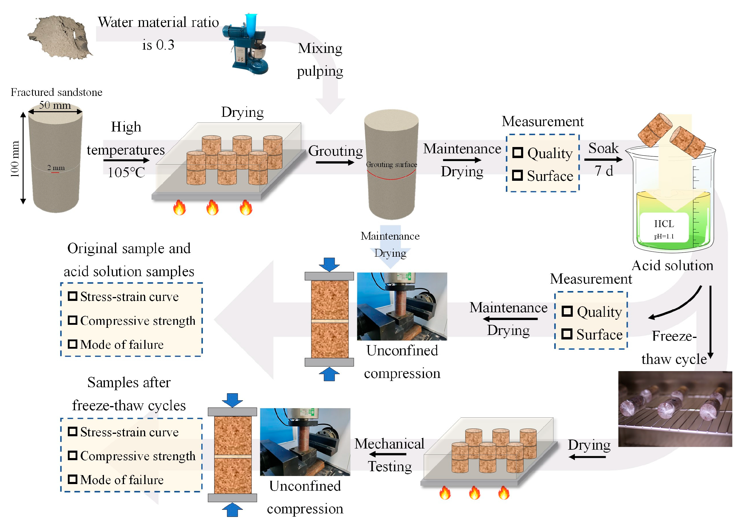
The slurry was prepared by a JJ-5 cement mortar mixer, and the fractured sandstone was fixed by a cylindrical mold. A small amount of slurry was absorbed by a syringe and quickly injected into the crack. After the slurry was filled with cracks, the grouting was stopped. The specimens were placed in the curing box together with the mold, and the mold was demolded after standard curing for 24 h. All specimens were subjected to 7 d standard curing. After the curing was completed, they were placed in a drying oven for drying. The temperature was set to 105 °C. After drying for 24 h, the quality of each specimen was weighed for the next test. The prepared grout-reinforced specimens are shown in Figure 3.
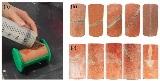
Figure 3.
Fracture-grout-reinforced specimens: (a) grouting process.; (b) full-penetrated fracture specimens.; (c) semi-penetrated fracture specimens.
2.3. Specimens Treatment
Unconfined compressive strength is an important index to evaluate the mechanical properties of grout-reinforced specimens. In this experiment, the unconfined compressive strength of grout-reinforced specimens is used as an index to analyze the original grout-reinforced specimens, the grout-reinforced specimens after soaking in an acidic solution, and the grout-reinforced specimens after a freeze–thaw cycle in an acidic environment.
Firstly, the drying test of the cured grout-reinforced specimens is carried out. The electric blast drying oven is used to dry the specimens. The working principle is to heat the air inside the equipment, then use the fan to make the air circulate inside and outside the object to be dried for heat exchange, and finally make the object to be dried or dried. A total of 60 specimens were placed in a drying oven for drying. The drying temperature was set at 105 °C, and the drying time was 24 h. The quality of grout-reinforced specimens was measured by a high-precision electronic scale after drying.
Secondly, the acid solution with pH = 1 was prepared by hydrochloric acid with a concentration of 1 mol/L, and the specimens were immersed in it. After soaking for 7 days, the specimens were taken out, and the surface water was dried and weighed. The freeze–thaw test was carried out by GDW225 high- and low-temperature alternating test chamber after wrapping the fresh-keeping film in some patterns. According to the literature [36], the freeze–thaw cycle temperature was set at 20–20 °C, the freezing time was 4 h, the melting time was 4 h, and the first cycle was 8 h. The number of cycles was set to 5, 10, 20, and 30 times. After the freeze–thaw cycle, the wrapped preservation film was removed, and the quality was weighed and put into the oven for drying.
Finally, the YZW-30 A multifunctional testing machine was used to test the compressive strength of the specimens, and the unconfined compressive strength and failure mode were obtained. The test flow is shown in Figure 4.
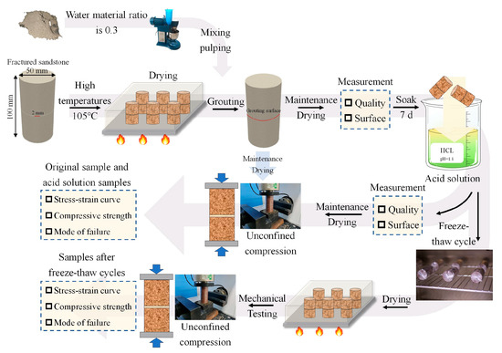
Figure 4.
Test flow chart.
3. Results and Discussion
3.1. Changes in Apparent Characteristics
The immersion of the acidic solution caused obvious corrosion on the crack reinforcement surface of the grout-reinforced specimens, and the sandstone also showed obvious acidic corrosion traces.
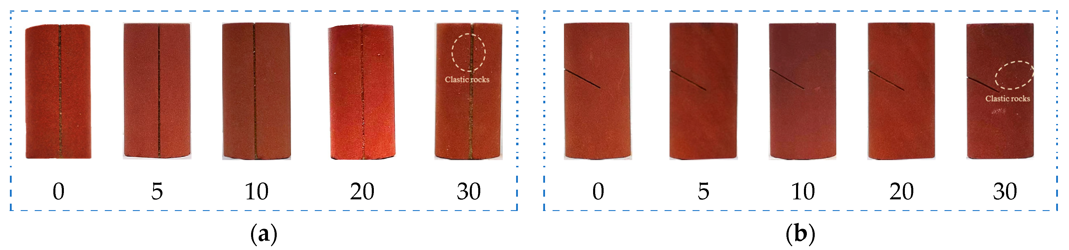
It can be seen in Figure 5 that the acidic solution immersion caused significant corrosion of the fracture reinforcement surface of the specimens, and the sandstone also showed more obvious traces of acidic corrosion, and in the same environment (pH = 1.1), the corrosion of the grout reinforcement surface of the full penetration fracture specimens corroded by the acidic solution was significantly less than that of the fracture grout reinforcement surface of the half penetration fracture specimens.
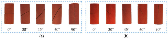
Figure 5.
Surface changes after soaking in acidic solution: (a) full-through fracture grout-reinforced specimens; (b) semi-through fracture grout-reinforced specimens.
From Figure 6 of the change in surface area of the specimens with different freeze–thaw cycles, it can be seen that as the number of freeze–thaw cycles increases, the surface area of the specimens decreases, the debris on the surface of the specimens increases, and the debris produced on the surface of the specimens after 30 freeze–thaw cycles is the most. It can be seen that most of the debris is the spalling of the grouting material under the influence of the acidic environment and the coupling of freeze–thaw cycles. It can be seen that with the increase of the number of freeze–thaw cycles, the concave and convex phenomenon on the surface of red sandstone becomes more and more obvious. It can be clearly observed that the powder on the surface of red sandstone falls off, indicating that the physical properties of the grout-reinforced specimens under the coupling of acidic environment and freeze–thaw cycles are degraded and its performance decreases with the increase of freeze–thaw cycles.
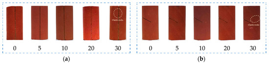
Figure 6.
The sample surface changes after different freeze–thaw cycles: (a) fully penetrated specimens with a crack angle of 90°; (b) semi-penetrated specimens with a crack angle of 30°.
3.2. Mass Loss under Acid Freeze–Thaw
An electronic balance with a precision of 0.01 g was used for mass weighing. Before weighing, the specimens needed to be dried. After the specimens were dried, they were weighed and recorded before and after the specimens treatment. By comparing the drying quality of grout-reinforced specimens before and after treatment, the mass loss rate of grout-reinforced specimens with different crack dip angles can be obtained.
The mass loss rate is calculated by the formula:
In the formula:
S—specimens mass loss rate after treatment, %;
mg—dry weight of specimens before treatment, g;.
ms—dry mass of specimens after treatment, g.
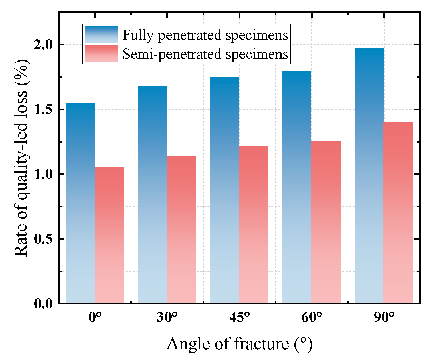
The mass loss rate of the test block is classified according to different degrees of fracture penetration and different angles of fracture inclination. The mass loss rate of each test block is shown in Figure 7. In terms of the degree of fracture penetration, the mass loss rate of grout and solid in the full-thickness fracture is greater than that in the half-thickness fracture. In terms of fracture angle, the mass loss rate of grout and solid increases with increasing angle.

Figure 7.
Rate of quality-led loss after soaking in an acidic solution.
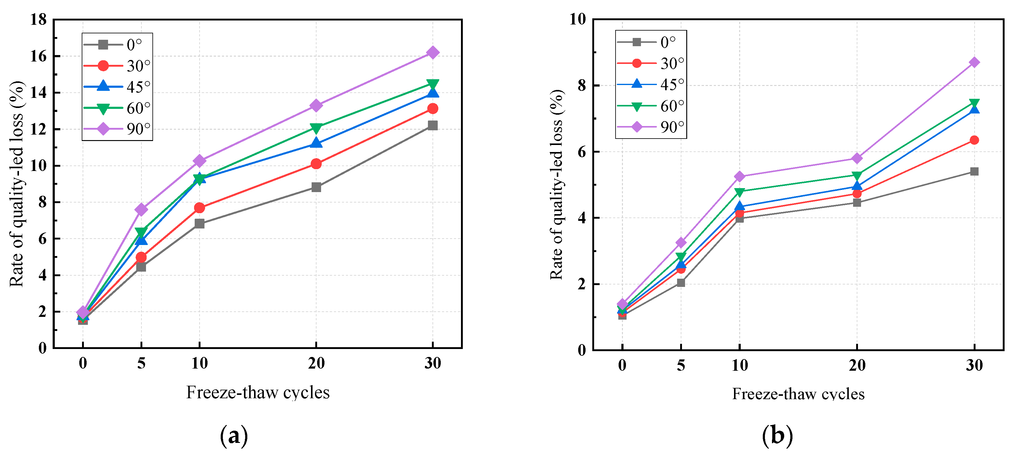
The mass loss rate of the test block was classified according to different degrees of fracture penetration and different angles of different freeze–thaw cycles fracture inclination. The mass loss rate of each test block is shown in Figure 8. In terms of fracture penetration degree, the mass loss rate of grouting with solid in the full-thickness fracture was greater than that in the half-thickness fracture. In the angle of fracture, the mass loss rate of grout-reinforced specimens increases as the angle increases. The reasons for the deterioration in quality are as follows: firstly, the corrosion resistance of the grouting material is weaker than that of the sandstone, and secondly, the combination of grout-reinforced specimens increases with the increase in the inclination angle. From the analysis of fracture penetration degree, the mass loss rate of full-thickness fracture grout-reinforced specimens is obviously larger than that of half-thickness fracture grout-reinforced specimens, which is similar to the reason why the mass loss rate changes with the fracture. The area of the reinforcement surface of full-through fracture grout-reinforced specimens is obviously greater than that of semi-through fracture grout-reinforced specimens. The mass loss rate of grout and solid is proportional to the area of the grouted reinforcement surface. The larger the area of the grouted reinforcement surface, the larger the area in contact with the acid solution and the corresponding mass loss rate.
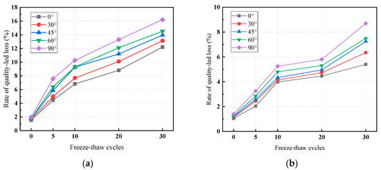
Figure 8.
Rate of quality-led loss after different freeze–thaw cycles: (a) full-through fracture grout-reinforced specimens; (b) semi-through fracture grout-reinforced specimens.
3.3. Strength Change
3.3.1. Strain–Stress Curve
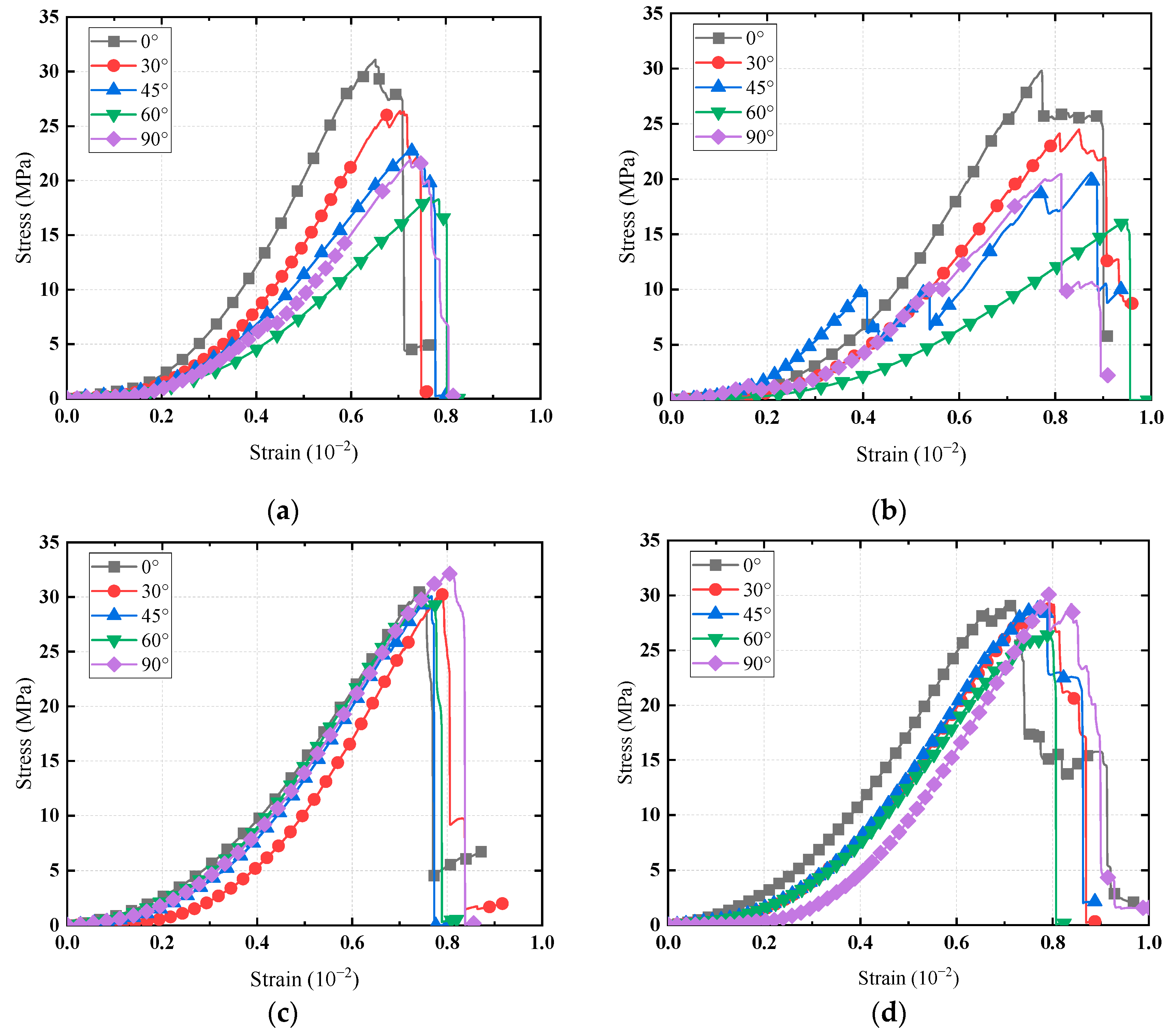
The stress–strain curves of grout-reinforced specimens after soaking in acid solution with different degrees of penetration are shown in Figure 9. Similar to the original version of grout-reinforced specimens, the stress–strain curves of grout-reinforced specimens after soaking in acid solution also show the characteristics of brittle materials of grout-reinforced specimens, and the failure stages are also divided into four stages: compaction stage, linear elastic stage, crack propagation stage, and failure stage. However, unlike the original model of grout-reinforced specimens, the crack propagation stage of grout-reinforced specimens after soaking in acid solution increased significantly, and the microcrack propagation stage of grout-reinforced specimens injection in the half section was larger than that of grout-reinforced specimens injection in the full section. As can be seen from the figure, regardless of the original grout-reinforced specimens or the grout-reinforced specimens after erosion in acid environment, the stress–strain curve of the full-through fracture grout-reinforced specimens with crack inclination of 60° does not appear in the more obvious crack expansion stage of the other fracture grout-reinforced specimens. On the contrary, the stress–strain curve drops rapidly after the peak value is reached. The reasons for this phenomenon are analyzed. On the one hand, the crack angle reaches the angle required for sliding shear failure of fracture grout-reinforced along the crack grouting surface. On the other hand, the surface of the prefabricated crack is smooth, and the sliding shear failure along the crack angle will still occur after the acid solution erosion, and the residual strength is approximately 0.
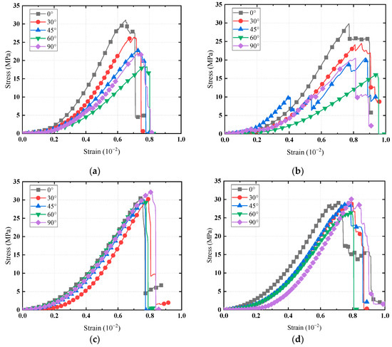
Figure 9.
Grout-reinforced specimens unconfined compressive stress–strain curve: (a) full-through fracture grout-reinforced specimens; (b) full-through grout-reinforced specimens after soaking in acidic solution; (c). semi-through fracture grout-reinforced specimens; (d) semi-through fracture grout-reinforced specimens after soaking in acidic solution.
3.3.2. Strength Comparison
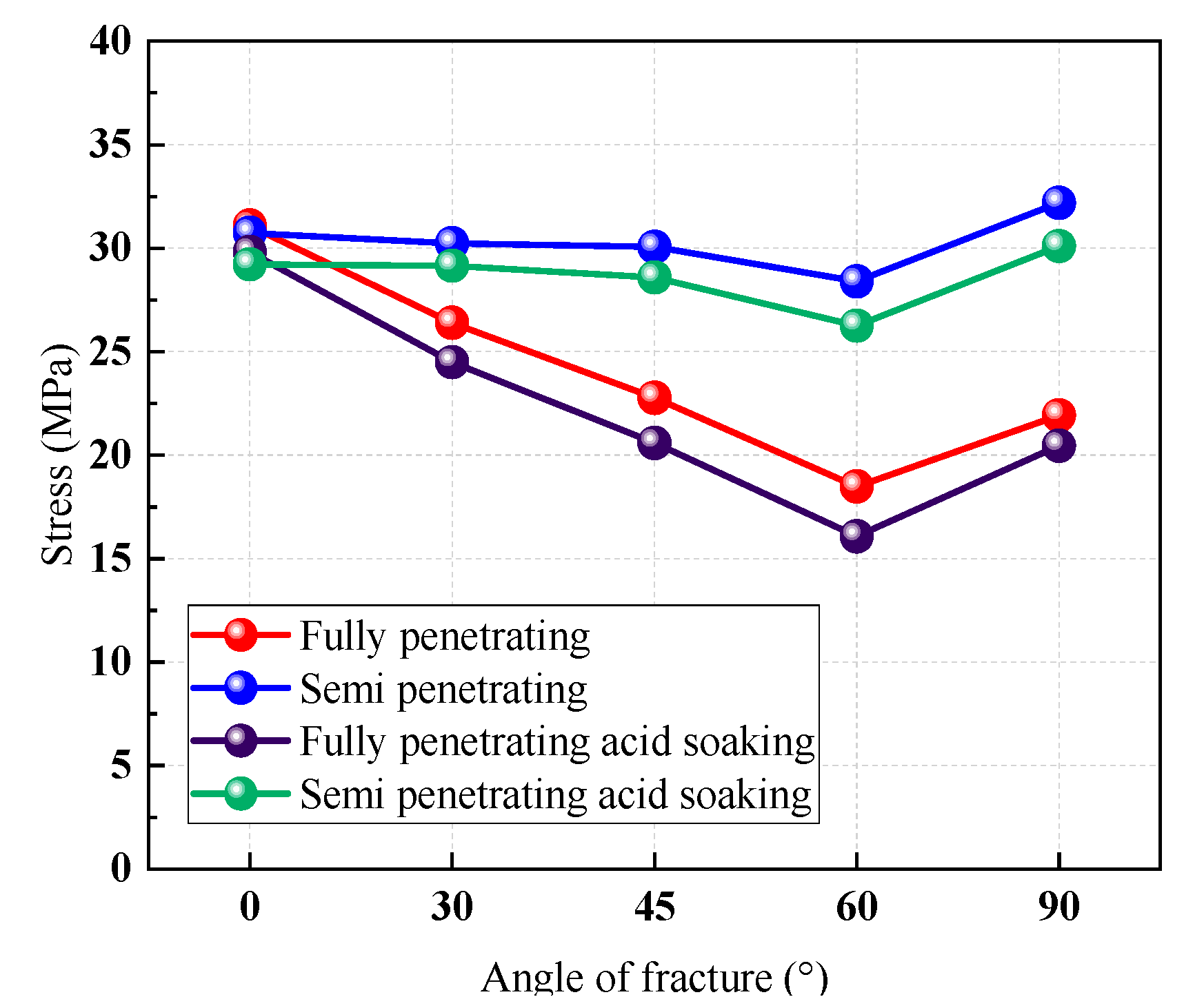
For the full-through fracture grout-reinforced specimens, it can be seen from the data in Figure 10 that after soaking in an acid solution, the change law of the compressive strength of the full-through fracture grout-reinforced specimens is similar to that of the original grout-reinforced specimens. The angle of immersion increases from 0° to 60°, and the compressive strength of the solid addition gradually decreases. Meanwhile, the compressive strength of the grout-reinforced specimens for the 90° crack is between 45° and 60°. The compressive strength of grout-reinforced specimens after soaking in an acid solution is significantly lower than that of untreated grout-reinforced specimens, and with the increase of fracture angle, the compressive strength of grout-reinforced specimens after soaking in acid solution is greater than that of untreated fracture grout-reinforced specimens. The uniaxial compressive strength of fracture grout-reinforced specimens with fracture inclinations of 0°, 30°, 45°, 60°, and 90° decrease by 4.11%, 7.19%, 9.57%, 13.03%, and 6.84%, respectively. Compared to the full-through fracture grout-reinforced specimens, the correlation between the strength of the semi-through fracture grout-reinforced specimens and the fracture inclination angle is lower between 0° and 60°, and the compressive strength of the specimen is greatest when the fracture is 90°.
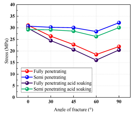
Figure 10.
Comparison of the strength of grout-reinforced specimens as original sample and after treatment in an acidic environment.
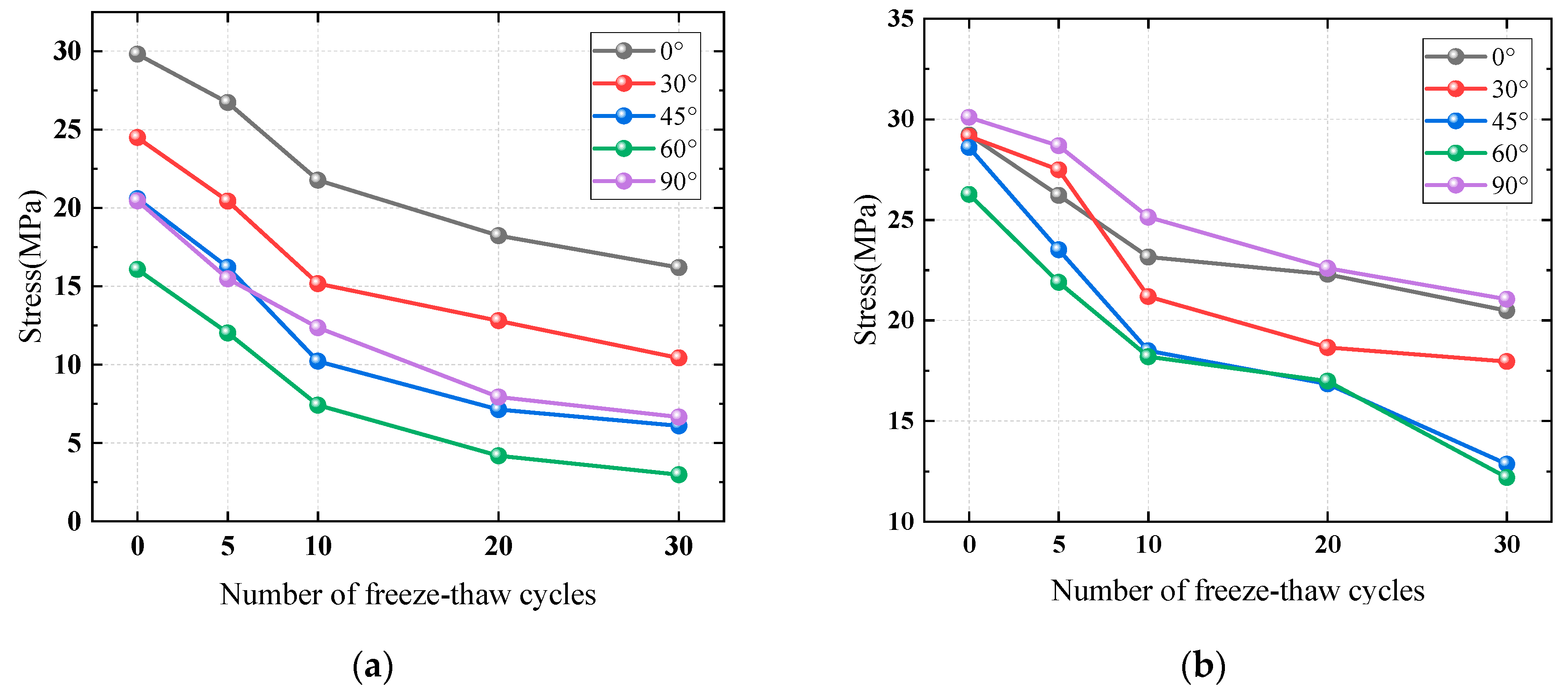
For full-through grout-reinforced specimens after different freeze–thaw cycles in an acidic environment when the number of freeze–thaw cycles is zero, five, and ten, the compressive strength decline of the sample is close to a straight line, and the decline rate of compressive strength gradually decreases after 20 freeze–thaw cycles and 30 freeze–thaw cycles. When the number of freeze–thaw cycles was five, the uniaxial compressive strength decreased from 26.72 MPa to 12.02 MPa with a decrease of 55.01%. When the number of freeze-thaw cycles was 10, the uniaxial compressive strength decreased from 21.76 MPa to 7.41 MPa, a decrease of 65.95%. When the number of freeze–thaw cycles is 20, the uniaxial compressive strength decreases from 18.23 MPa to 4.18 MPa, a decrease of 77.07%. When the number of freeze–thaw cycles was 30, the uniaxial compressive strength decreased from 16.19 MPa to 2.98 MPa, a decrease of 81.6%. It can be seen that as the number of freeze–thaw cycles increases, the compressive strength of the grout and solid with a crack angle of 60° decreases more than that of the grout and solid with a crack angle of 0°.
For semi-through grout-reinforced specimens after different freeze–thaw cycles in an acidic environment when the number of freeze–thaw cycles is five, the uniaxial compressive strength decreases from 28.68 MPa to 21.89 MPa, a decrease of 23.67%. When the number of freeze–thaw cycles is 10, the uniaxial compressive strength decreases from 25.12 MPa to 18.18 MPa, a decrease of 27.62%. When the number of freeze–thaw cycles was 20, the uniaxial compressive strength decreased from 22.58 MPa to 16.84 MPa, a decrease of 25.42%. When the number of freeze–thaw cycles was 30, the uniaxial compressive strength decreased from 21.05 MPa to 12.18 MPa, a decrease of 42.13%. It can be seen that the compressive strength of semi-through grout-reinforced specimens decreases relatively less with the increase in the number of freeze–thaw cycles compared to full-through grout-reinforced specimens.
It can be seen from the strength changes in the Figure 11 that overall, the strength deterioration damage of full–through grout-reinforced specimens under the influence of a freeze–thaw cycle in an acidic environment is more obvious than that of semi-through grout-reinforced specimens, and the strength change of full-through grout-reinforced specimens is more regular than that of semi-through grout-reinforced specimens. The main reason is that the strengths of grouting materials and sandstone are different. The deterioration of grouting materials caused by acidic environments and freeze–thaw cycles is greater.
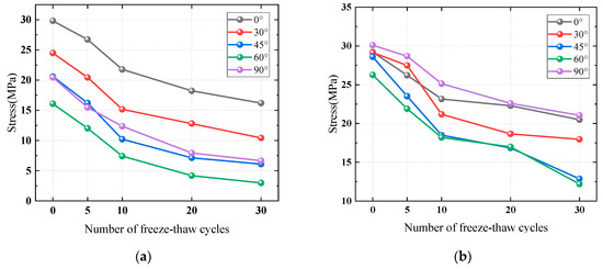
Figure 11.
The peak strength of full-through and semi-through grout-reinforced specimens changes with the number of freeze–thaw cycles: (a) full-through grout-reinforced specimens; (b) semi-through grout-reinforced specimens.
3.4. Microstructure Analysis
In order to explore the microstructure of fractured sandstone grout-reinforced specimens under an acidic environment and freeze–thaw cycles, the specimens without treatment, soaking in acidic solution, freezing and thawing in an acidic environment for 5 times, 10 times, 20 times, and 30 times were selected as the scanning specimens, and the scanning electron microscope scanning test was carried out. Six different magnification images of 200, 500, 1000, 3000, 5000, and 10,000 times were obtained, respectively, and the action mechanism of an acidic environment and a freeze–thaw cycle on sandstone and grout-reinforced specimens was revealed.
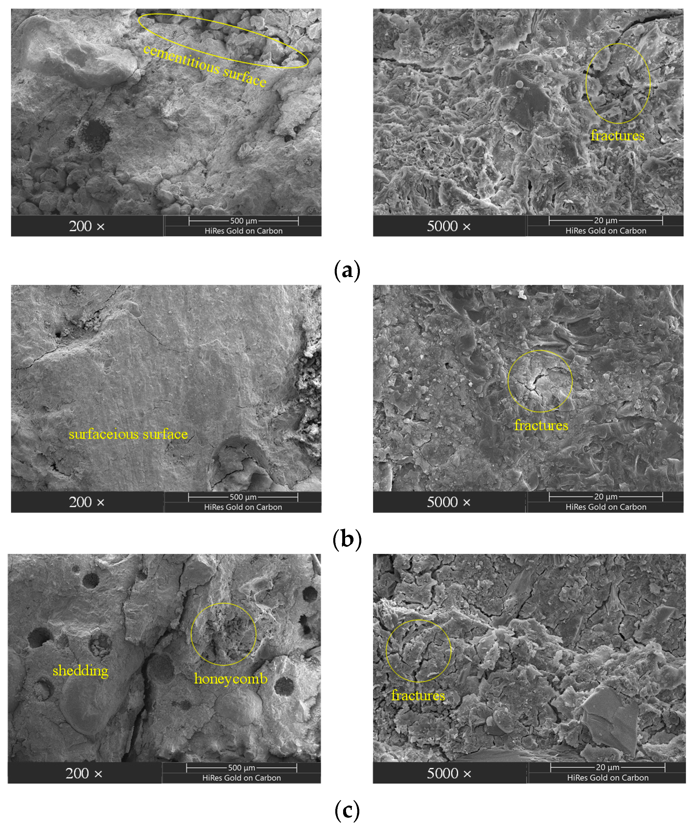
In the microstructure of the original specimens and under the observation of a 200 times electron microscope, the grouting material and sandstone are well cemented, the grouting material and sandstone are closely structured, a small number of cracks are found on the surface, the pores are small, and there are a small number of disordered mineral particles in the rock mass. After being magnified 5000 times, the surface of sandstone mineral crystal is relatively smooth, and the surface cracks of grouting material are disorderly distributed. In the microstructure of grout-reinforced specimens after 7 days of acid solution immersion and under the observation of a 200 times electron microscope, there are different degrees of corrosion on the surface of the grouting material and the sandstone, and compared with the original specimens, the development of micro cracks increases, but the development of large cracks decreases, the surface of main mineral crystals is smooth, and there is a large area of smooth area. After being magnified 5000 times, it can be seen that the acid corrosion of grouting material and sandstone is more significant, and the crack of grouting material extends and expands. The above conclusions show that under the influence of acid solution corrosion, grouting and solid grouting materials and sandstone react with the acid solution. Free mineral particles are generated, and free mineral particles are distributed around pores and cracks.
The microstructure of grout-reinforced specimens after 30 acid environment freeze–thaw cycles is shown in Figure 12c. By comparing images with the different number of freeze–thaw cycles under the observation of a 200 times electron microscope, it can be seen that the grout-reinforced specimens after different freeze–thaw cycles have different degrees of damage. After five freeze–thaw cycles, there is a small range of particle shedding between grout-reinforced specimens grouting material and sandstone surface, and there are obvious free mineral particles on the surface of sandstone due to freeze–thaw cycles.
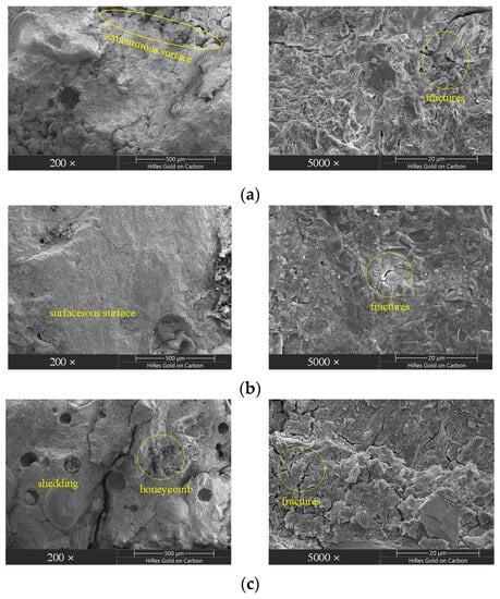
Figure 12.
Scanning electron microscopy images of specimens after different treatments: (a) original specimens; (b) acid erosion specimens; (c) after 30 freeze-thaw cycles of the specimens.
Amplifying the electron microscope to 5000 times, it can be seen that the surface of the grouting material has obvious crack development and expansion, and the surface of the sandstone has an obvious “honeycomb” phenomenon. Due to the coupling effect of acid solution corrosion and a freeze–thaw cycle, the cementation of grouting materials and minerals in sandstone is obviously weakened. After ten freeze-thaw cycles, the grouting and solid grouting material is more obvious than the sandstone surface shedding after five freeze-thaw cycles, the micro-crack development on the surface of the grouting material increases, and the “honeycomb” area on the sandstone surface is more obvious. When the number of freeze–thaw cycles reaches 30 times, the loss of grouting and solid particles leads to a rougher surface, and the number of surface holes and cracks increases significantly. The surface roughness changes significantly compared with the original specimens of grouting and solid.
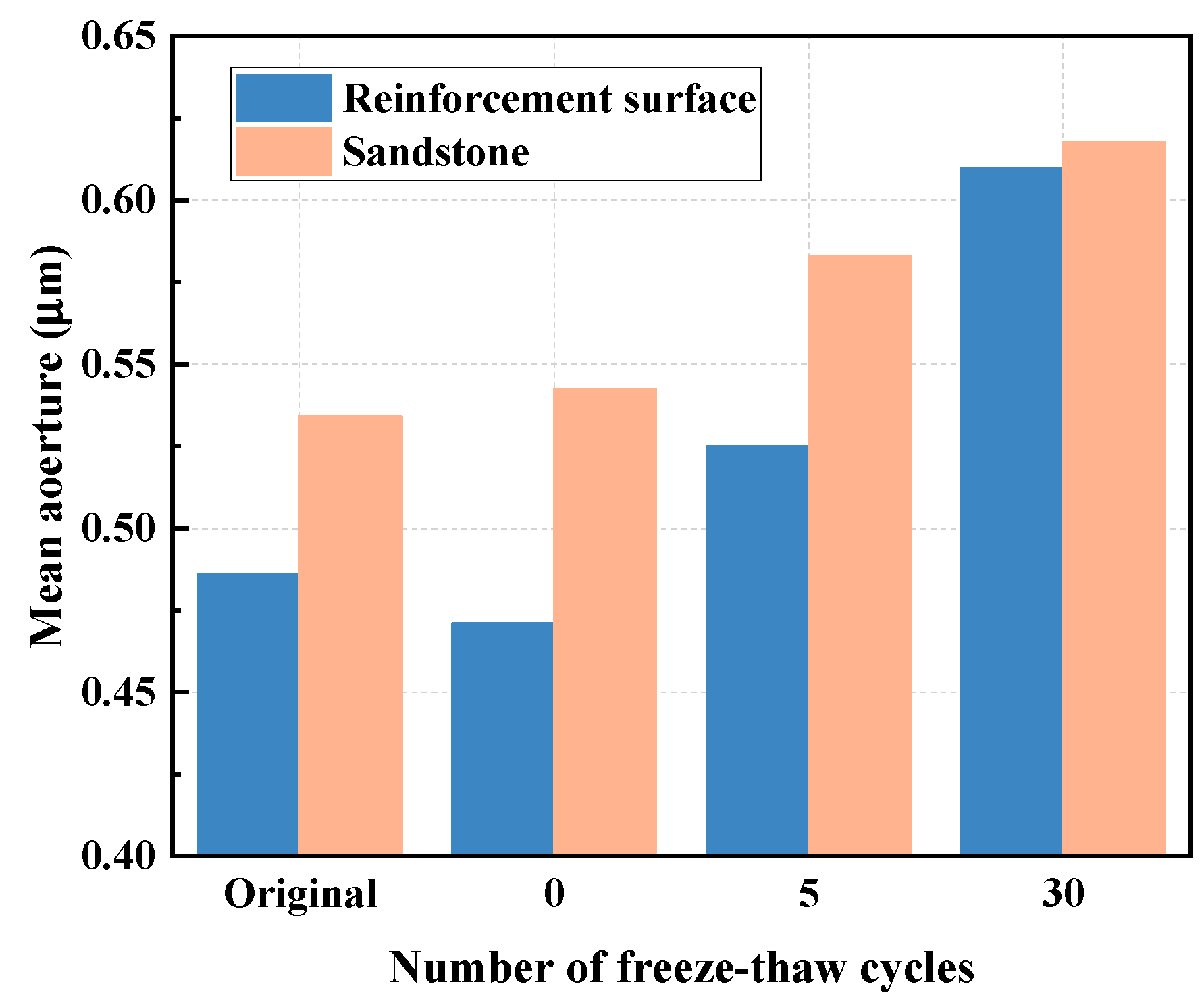
Binarisation was carried out on the original sample after acid soaking the grouted surface with five and thirty freeze–thaw cycles in an acidic environment, and the scanning electron microscope photographs of sandstone and the average pore diameter in pore parameters were selected for analysis. The relationship between the grouted surface and the average pore diameter of the sandstone with the acid freeze–thaw times is shown in Figure 13. It can be seen from the figure that the average pore diameter of the grouted surface (grouting material) decreases compared to the original sample after the grout and solid are eroded by acid solution, which is because the large particles in the material dissolved by the acid substance fill the pores with a large pore diameter. Therefore, the micro grouted surface becomes smooth. As the freeze–thaw time increases, the average pore diameter of the sample continuously increases. It shows that the damage of the micro-grouting reinforced surface is intensified by freeze–thaw in an acidic environment. For sandstone, with the increase of acid erosion and the number of freeze–thaw cycles in an acidic environment, the average pore diameter of the samples increased, which is consistent with the conclusion obtained by observing the scanning electron microscopy images. Overall, as the number of freeze–thaw cycles in an acidic environment increases, the difference between the average pore diameter of grouting materials and sandstone decreases, indicating that the damage caused by freeze–thaw cycles in an acidic environment is greater than that caused to sandstone and further indicate that the reinforcement surface of grouting with solid is the weakest point.
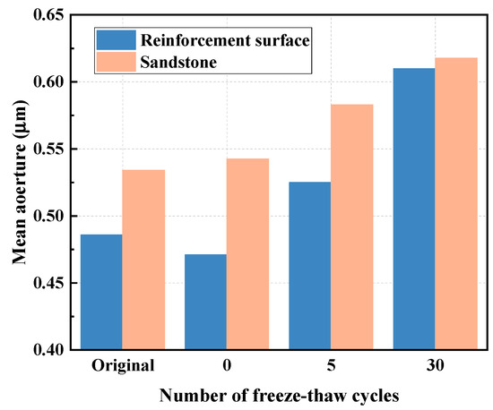
Figure 13.
Different treatment methods of grout-reinforced specimens average aperture.
4. Conclusions
Through the fracture grouting test of FCM grouting material and the unconfined compression test and electron microscope scanning of fractured sandstone grout-reinforced specimens, the following conclusions are obtained.
(1) The flow ability and condensation ability of FCM under low water–material ratio are five times that of P.O 42.5 cement, which meets the relevant requirements of grouting materials, and FCM has certain expansibility, which is well cemented with red sandstone. The grout-reinforced specimens formed by the FCM and sandstone can reach the original rock or even exceed the original rock strength.
(2) Grout-reinforced specimens and sandstone belong to brittle materials, and the degree of penetration and inclination angle of grout-reinforced specimens fracture determine the stress–strain relationship of the specimens. There is a certain similarity in the failure process of the specimens, which is composed of four stages: compaction stage, elastic deformation stage, crack propagation stage, and failure stage. For the full cracks, the correlation between the compressive strength of grout-reinforced specimens and the dip angle of cracks is high. When the dip angle increases from 0° to 60°, the compressive strength of the reinforcement gradually decreases, and the compressive strength of grout-reinforced specimens with 90° cracks is between 45° and 60°.
(3) The acidic environment and freeze–thaw cycle will erode the grout-reinforced specimens, mainly the erosion of the grout-reinforced specimens surface, and as the fracture increases, the degree of erosion increases, and the strength of the grout-reinforced specimens decreases, and the degree of fracture penetration and inclination determine the degree of reduction of the strength of the grout-reinforced specimens.
(4) FCM grouting material is well cemented with red sandstone. After soaking in acidic solution and freeze–thaw cycles in an acidic environment, the surface of grouting material appears to have particle loss, and the surface of the sandstone appears as a “honeycomb” area. With the increase of freeze–thaw cycles, the area of particle loss and honeycomb area increases.
Author Contributions
Methodology, D.Y. and J.Z.; Formal analysis, X.H.; Investigation, X.H.; Resources, D.Y.; Data curation, D.Y.; Writing—original draft, D.Y.; Writing—review & editing, X.H. and T.L.; Supervision, X.H. and T.L.; Project administration, J.Z.; Funding acquisition, J.Z. and T.L. All authors have read and agreed to the published version of the manuscript.
Funding
This research was funded by National Natural Science Foundation of China: U2006213; National Natural Science Foundation of China: 42277139; National Natural Science Foundation of China: 42207172; China Postdoctoral Science Foundation: 2022M712989; Natural Science Foundation of Shandong Province: ZR2022QD103.
Data Availability Statement
No new data were created, or where data is unavailable due to privacy or ethical restrictions.
Conflicts of Interest
The authors declare no conflict of interest.
References
- Xue, Y.G.; Kong, F.M.; Yang, W.M.; Qiu, D.H.; Su, M.X.; Fu, K.; Ma, X.M. Main unfavorable geological conditions and engineering geological problems along Sichuan—Tibet railway. Chin. J. Rock Mech. Eng. 2020, 39, 445–468. [Google Scholar]
- Ma, W.; Wang, D.Y. Studies on frozen soil mechanics in China in past 50 years and their prospect. Chin. J. Geotech. Eng. 2012, 34, 625–640. [Google Scholar]
- Bai, S.; Liu, Q.Z.; Wu, H.D. Relation of ice conditions to climate change in the Bohai Sea of China. Acta Oceanol. Sin. 2001, 20, 331–342. [Google Scholar]
- Gong, D.Y.; Wang, S.W.; Zhu, J.H. East Asian winter monsoon and Arctic Oscillation. Geophys. Res. Lett. 2001, 28, 2073–2076. [Google Scholar] [CrossRef]
- Tang, M.N.; Hong, J.L.; Liu, Y.; Sui, J.P.; Zhao, Q. Statistical analysis of climatic factors impacting on the Bohai Sea ice. Mar. Sci. Bull. 2015, 34, 152–157. [Google Scholar]
- Yao, L.; Su, J. Relationships between Bohai Sea ice and Siberian high and possible connections between Bohai Sea ice and north Atlantic Oscillation. Period. Ocean Univ. China 2018, 48, 1–12. [Google Scholar]
- Ling, X.; Han, X. Research on the pollution prevention and control mechanism of watershed-estuary-coastal waters of Bohai Sea. Mar. Environ. Sci. 2021, 40, 970–974. [Google Scholar]
- Deng, Z.; Duan, W.; Wang, S.B.; Zhou, Y.T. Port Development Level and Spatial Spillover effects in the Bohai Rim. Areal Res. Dev. 2023, 42, 26–31. [Google Scholar]
- Wang, Z.D.; Zhang, X.L.; Sun, D.Q.; Sun, H.Y. Spatial-temporal evolution of the logistics network structure of inter-regional urban agglomeration before and after the construction of the Bohai Strait cross-sea channel. Geogr. Res. 2020, 39, 585–600. [Google Scholar]
- Yuan, Y.; Pan, P.Z.; Zhao, S.K.; Wang, B.; Song, G.H. The failure process of marble with filled crack under uniaxial compression based on digital image correlation. Chin. J. Rock Mech. Eng. 2018, 37, 339–351. [Google Scholar]
- Taber, S. The mechanics of frost heaving. J. Geol. 1930, 38, 303–317. [Google Scholar] [CrossRef]
- O’Neill, K.; Miller, R.D. Exploration of a rigid ice model of frost heave. Water Resour. Res. 1985, 21, 281–296. [Google Scholar] [CrossRef]
- Zhang, Y.; Lu, Y.Y.; Liu, T. Undrained Horizontal-Moment Bearing Capacity of Caisson Foundations in Over-consolidated Clay Considering Effects of Gap. Mar. Georesour. Geotechnol. 2019, 39, 255–266. [Google Scholar] [CrossRef]
- Joseph, W.; Bernard, H. A theoretical model of the fracture of rock during freezing. GeoScienceWorld 1985, 96, 336–346. [Google Scholar]
- Wang, L.G.; Li, M.Y.; Wang, X.Z. Study on mechanisms and technology for bolting and grouting in special soft rock roadways under high stress. Chin. J. Rock Mech. Eng. 2005, 24, 2889–2893. [Google Scholar]
- Brantberger, M.; Stille, H.; Eriksson, M. Controlling grout spreading in tunnel grouting Analyses and developments of the gin-method. Tunn. Undergr. Space Technol. 2000, 15, 343–352. [Google Scholar] [CrossRef]
- Liu, T.; Zhang, Y.; Meng, Q.S. Numerical Investigation and Design of Suction Caisson for On-bottom Pipelines under Combined V-H-M-T Loading in Normal Consolidated Clay. Ocean Eng. 2023, 274, 113997. [Google Scholar] [CrossRef]
- Zhang, D.L.; Sun, Z.Y.; Chen, T.L. Composite grouting technology for subsea tunnels and its engineering application. Chin. J. Rock Mech. Eng. 2019, 38, 1102–1116. [Google Scholar]
- Kuang, J.Z.; Zan, Y.W.; Wang, J. Geotechnical Grouting Theory and Engineering Practice; Science Press: Beijing, China, 2001; pp. 1–5. [Google Scholar]
- Ma, H.; Liu, Q. Prediction of the peak shear strength of sandstone and mudstone joints infilled with high water-cement ratio grouts. Rock Mech. Rock Eng. 2017, 50, 2021–2037. [Google Scholar] [CrossRef]
- Lee, J.; Lee, T. Effects of high CaO fly ash and sulfate activator as a finer binder for cementless grouting material. Materials 2019, 12, 3664. [Google Scholar] [CrossRef]
- Lu, Y.; Wang, L.; Li, Z. Experimental study on the shear behavior of regular sandstone joints filled with cement grout. Rock Mech. Rock Eng. 2017, 50, 1321–1336. [Google Scholar] [CrossRef]
- Jiang, B.; Gu, S.; Zhang, G. Strainburst process of marble in tunnel-excavation-induced stress path considering intermediate principal stress. J. Cent. South Univ. 2019, 26, 984–999. [Google Scholar] [CrossRef]
- Liu, Q.; Tian, Y.; Liu, D. Updates to JRC-JCS model for estimating the peak shear strength of rock joints based on quantified surface description. Eng. Geol. 2017, 228, 282–300. [Google Scholar] [CrossRef]
- Tatone, B.; Grasselli, G. Characterization of the effect of normal load on the discontinuity morphology in direct shear specimens using X-ray micro-CT. Acta Geotech. 2015, 10, 31–54. [Google Scholar] [CrossRef]
- Nasir, O.; Fall, M. Shear behaviour of cemented pastefill-rock interfaces. Eng. Geol. 2008, 101, 146–153. [Google Scholar] [CrossRef]
- Tian, H.; Chen, W.; Yang, D. Experimental and numerical analysis of the shear behaviour of cemented concrete–rock joints. Rock Mech. Rock Eng. 2014, 48, 213–222. [Google Scholar] [CrossRef]
- Wang, Z.; Li, L.; Wang, C.Y. Experimental study on failure of cracked rock-like material after grout-reinforced specimens. J. Cent. South Univ. (Sci. Technol.) 2018, 49, 957–963. [Google Scholar]
- Wang, H.P.; Gao, Y.F.; Li, S.C. Uniaxial Experiment Study on Mechanical Properties of Reinforced Broken Rocks Pre-and-post Grouting. Chi. Tunn. Undergr. Space Technol. 2007, 1, 27–31+39. [Google Scholar]
- Chen, X.; Li, D.W.; Wang, L.X.; Zhang, S.F. Experimental study on effect of spacing and inclination angle of joints on strength and deformation properties of rock masses under uniaxial compression. Chin. J. Geotech. Eng. 2014, 36, 2236–2245. [Google Scholar]
- Wong, R.H.C.; Chau, K.T. Crack coalescence in a rock-like material containing two cracks. Int. J. Rock Mech. Min. Sci. 1998, 35, 147–164. [Google Scholar] [CrossRef]
- Bobet, A.; Einstein, H.H. Fracture coalescence in rock-type materials under uniaxial and biaxial compression. Int. J. Rock Mech. Min. Sci. 1998, 35, 863–888. [Google Scholar] [CrossRef]
- Chai, S.B.; Wang, H.; Yu, L.; Shi, J.; Abi, E. Experimental study on static and dynamic compression mechanical properties of filled rock joints. Lat. Am. J. Solids Struct. 2020, 17, e264. [Google Scholar] [CrossRef]
- Zhang, J.F.; Xu, R.P.; Liu, Y.; Zhang, H.M. Study on micro-pore evolution law and shear mechanical behavior of grouting fractured rock mass under freeze-thaw cycle. Chin. J. Rock Mech. Eng. 2022, 41, 676–690. [Google Scholar]
- Shen, J.; Liu, B.G.; Chen, J.; Li, Y.F.; Cheng, Y.; Song, Y. Experimental study on mechanical properties of diabase fracture-grout-reinforced specimens. Chin. J. Rock Mech. Eng. 2020, 39, 2804–2817. [Google Scholar]
- Shen, Y.J.; Yang, G.S.; Rong, T.L.; Liu, H.; Lu, W.Y. Proposed scheme for freeze-thaw cycle tests on rock. Chin. J. Geotech. Eng. 2016, 38, 1775–1782. [Google Scholar]


Disclaimer/Publisher’s Note: The statements, opinions and data contained in all publications are solely those of the individual author(s) and contributor(s) and not of MDPI and/or the editor(s). MDPI and/or the editor(s) disclaim responsibility for any injury to people or property resulting from any ideas, methods, instructions or products referred to in the content. |
© 2023 by the authors. Licensee MDPI, Basel, Switzerland. This article is an open access article distributed under the terms and conditions of the Creative Commons Attribution (CC BY) license (https://creativecommons.org/licenses/by/4.0/).