Abstract
A pilot hydrocyclone plant was used to concentrate medium-grade celestine ore (67% celestine) from the Montevive deposit in Granada (Spain) by using a dense media concentration (DMS) process. To optimize the concentration process, several types of heavy minerals (coarse, fine C40 ferrosilicon and/or magnetite) were used to prepare a dense media with a constant density of 3.0 kg/L. Then, the dense media (loaded with run-of-mine celestine mineral) was fed into the hydrocyclone system. The mineral was then separated into two streams, the first containing the mineral fractions that float (over stream) and the second containing fractions that sink (under stream) in the dense media. Next, the heavy minerals (ferrosilicon and/or magnetite) were recovered from the dense media using magnetic separation. The celestine mineral recovered from each stream was divided into two fractions with particles size above or below 250 μm to study the effect of the mineral particle size on the separation process. Their mineral composition was quantified by X-ray diffraction (XRD) using the Rietveld method. The celestine is preferentially concentrated in the under stream in the mineral fraction with particles larger than 250 μm (up to 90% celestine). The optimum results (highest % of celestine) were obtained after desliming and using the ferrosilicon C40 medium, which has the smallest particle size (<40 μm) of all media used. The results of this study show that medium-grade celestine mineral accumulated in the mine tailings can be efficiently concentrated using a DMS process, which could help in making mine operations more sustainable and eco-friendlier.
1. Introduction
Access to affordable raw materials and minerals is essential for our industrial, social, and technological progress. A recent European Union (EU) study titled Critical Raw Materials for Strategic Technologies and Sectors defined 30 materials as critical raw materials (CRM), including aluminum, lithium, titanium, and strontium for the first time in 2021 [1]. This report also highlights the vulnerable situation of the EU regarding its dependence on critical materials from other countries. The Montevive mine (Granada, Spain) contains the largest European deposit of celestine, which is the main source of strontium. The celestine ore consists of mineralized stromatolites, originally made of calcite, which have been partially replaced by celestine [2,3,4]. In addition to celestine and calcite, the celestine mineral also contains other minority phases such as dolomite, strontianite, quartz, clay minerals (kaolinite, paragonite, and illite), iron oxides, and hydroxides, which are part of a finer mineral fraction.
Canteras Industriales S.L. (CI), the company that operates the mine, has traditionally processed only high-grade mineral (approximately 80% celestine), while the lower-grade mineral has accumulated in mine tailings and dumps. To make mine operation more sustainable and decrease its impact, CI is exploring new ways to process and concentrate the medium-grade mineral. Celestine mineral concentration and recovery would reduce mine operation costs by avoiding blasting and clearings, ground displacement, generation of residues, and fuel consumption. Overall, it would minimize the impact of the mine operation, making it more sustainable and eco-friendlier.
The most commonly used methods for celestine concentration are classification by particle size, which separates the minerals present according to their grain size [5,6,7,8,9,10,11,12,13,14,15]; gravimetric concentration by dense media (in hydrocyclones, drums, or spirals), which separates minerals by density differences and hydrodynamic drag [10]; and flotation methods, which use differences in the surface properties of minerals for separation [16,17]. Oil agglomeration methods have also been used to concentrate celestine [18,19].
The relative high density of celestine (3.96 kg/L) makes it susceptible to separation from other associated lower density minerals (i.e., quartz 2.65 kg/L, calcite 2.71 kg/L, illite 2.80 kg/L, dolomite 2.84 kg/L) using a dense medium. Dense media separation (DMS) methods separate the mineral of interest from the gangue minerals using a suspension of dense medium minerals operated in a circuit [20]. However, the dense medium is a heterogeneous suspension of finely ground particles of a different nature (dense medium minerals and raw ore mineral) in water. Thus, mineral particle size and shape, as well as the properties of the dense medium minerals (i.e., ferrosilicon, magnetite) used to prepare the dense medium influence the separation process [11,21,22]. The DMS method is considered practical for large particle sizes; however, some studies show good separation for particles as small as 25 µm [15,23,24]. Depending on the run-of-mine mineral’s particle size, the DMS process uses cyclones, drums, or baths for processing circuits [20]. In this study, considering the characteristics of the run-of-mine celestine mineral (particle size from 100 mm to 6 mm), a hydrocyclone system was chosen. The run-of-mine mineral in the suspension (in this case, celestine ore) is fed, at high pressure, into the top of the hydrocyclone system, entering it tangentially [25]. Then, the run-of-mine mineral components are separated by their densities and drag. The lighter mineral particles float and emerge in the over stream and the heavier mineral particles (e.g., celestine and strontianite) sink and emerge in the under stream (see Figure 1). However, in the hydrodynamic regime of the hydrocyclone, the mineral particles’ behavior is also affected by other factors (i.e., particle size and shape, flow rate).
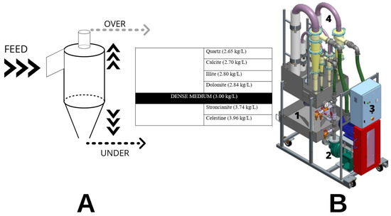
Figure 1.
(A) Hydrocyclone system used for the mineral separation and concentration process. The table shows the distribution of mineral phases that can be recovered in the two output streams (UNDER and OVER). (B) Pilot plant used for the experiments, with the main parts indicated with numbers (1—sump, 2—pump, 3—electric control cabinet, 4—hydrocyclone).
The effect of relevant parameters such as the cyclone dimensions, inlet feed pressure, particularly dense medium properties, and feed rates have been studied in the last few decades [8,10,25]. However, even though hydrocyclone design and basic operation are simple, there is still much to learn about their behavior and the effects of different operating parameters used to control mineral separation [21,26].
In this study, we explore parameter optimization of the DMS concentration process before scaling it up to a semi-industrial pilot plant. We examined the effects of the relevant parameters of plant operation, such as celestine mineral feed rate, mineral granulometry, heavy mineral suspension composition, and pressure limit of operation. In DMS, the rheology of the dense medium plays an important role in separation efficiency; therefore, we characterized the stability and viscosity of the suspensions used in the experiments [6,27].
We applied this methodology to concentrate medium-grade mineral (approx. 67% celestine) from Montevive mine tailings and detail the main results of the study. We also describe the benefits of this methodology in making celestine mining more sustainable and compatible with a circular economy.
2. Materials and Methods
2.1. Montevive Celestine Mineral
A sample of approximately 2000 kg of medium-grade mineral (65–69% celestine) from the Montevive mine tailings was collected. The chemical composition determined by X-ray fluorescence (XRF) showed that SrSO4 (70%) and CaCO3 (15–18%) were the main components. Other minority components (<10%) were MgCO3, SiO2, Al2O3, and Fe2O3. Additionally, the mineral composition was quantified by X-ray diffraction (XRD) using the Rietveld method, which showed that celestine (67.45%) and calcite (15.01%) were the main mineral phases and that other carbonates (dolomite and strontianite) and silicates (quartz and illite) were minority phases (<7.52%).
2.2. Sample Preparation
The run-of-mine (raw) celestine mineral was ground from 100 mm to 6 mm using a roll crusher (Figure S1A) in closed circuit with a sieve (FINTEC 542) (Figure S1B).
The ground celestine mineral (<6 mm particle size) was subjected to a desliming process, using the equipment shown in Figure S1C,D. The effect of desliming was studied by comparing the dense medium separation (DMS) with the mineral before (raw) and after finer fraction removal. A minimum of 16 kg of raw mineral was processed to prepare 10 kg of deslimed mineral for each experiment. (The mineral fraction below 61 µm corresponded to about 38%.) Samples subjected to the desliming process are denoted with a D at the end.
2.3. Dense Media
Ferrosilicon and magnetite are often used as heavy minerals in dense media separation due to their high density, coarser particle size distribution, and spherical particle shape [27]. Ferrosilicon is an alloy of iron and silicon, and magnetite is a natural iron oxide mineral (Fe3O4). The cost of ferrosilicon is higher than that of magnetite [11,21,22]. The DMS method was first applied in coal mining. At present, this method is used for the separation circuits of diamond and iron, and the pre-concentration of base metals and heavy minerals [11,20]. A suspension of intermediate density (between calcite and celestine) of around 3.00 kg/L was prepared using ferrosilicon (7.42 kg/L) and/or magnetite (DMS80, 4.80 kg/L) (ACOMET Metals and Minerals) in water. The elemental composition, physical properties and particle size distribution of ferrosilicon are given in Tables S1–S3. Tables S4 and S5 include the elemental composition and particle size distribution of magnetite.
Three different types of ferrosilicon (Table S4) with different particle sizes were used to prepare different dense media: Coarse Grade (CG), Fine (F), and Cyclone 40 (C40). They all have the same composition but were milled for different times. A mixture of intermediate-grain-size ferrosilicon (F) and magnetite (M) (with particle size 200–300 µm) at 33% (FM) was also used for dense media preparation.
2.3.1. Viscosity Determination
Viscosity data were analyzed using the relationship between shear rate and shear stress [27,28]. To determine the viscosity of each heavy mineral suspension (or slurry), the slurry was placed between two parallel plates and stress was applied by moving one plate relative to the other at a constant velocity. Due to the viscosity, a shear rate (with units of γ = dv/dy = s−1) is created in the fluid. The shear stress (τ = F/A, the force per unit area (Pa)) is proportional to the velocity profile generated in the fluid (Newton model).
The constant of proportionality (η) is the coefficient of viscosity, or resistance of the liquid to flow.
Samples of CG, F, C40, and FM suspensions, with a density of 3.00 kg/L, were measured at different temperatures (30–60 °C) using a Malvern Kinexus rheometer and a 20 mm diameter flat plate. The dynamic viscosity of the samples was determined according to the ASTM D445 protocol.
2.3.2. Stability Study
The stability of the medium suspensions was calculated following the procedure described by Bosman [6]:
- In a 250 mL measuring cylinder, 250 mL of medium was prepared (water and heavy mineral) at 3.00 kg/L (Figure S2A).
- Then, the medium was well-mixed, preventing it from adhering to the cylinder walls.
- Time and height data were taken from the dense medium column using a ruler and stopwatch (Figure S2B).
- Due to the fast-decanting speed, a video of the process was recorded (Figure S2C).
2.4. Dense Medium Separation Experiments
To concentrate the Montevive celestine mineral, a suspension of heavy mineral (ferrosilicon, magnetite, or a 2:1 mixture of both) in water was prepared with a density of 3.00 kg/L (intermediate between celestine and associated minerals). Therefore, the lighter associated mineral phases (quartz, calcite, illite, and dolomite) can be recovered in the over stream and the heavier mineral phases (strontianite and celestine) can be concentrated and recovered in the under stream (Figure 1A).
2.4.1. Laboratory Scale Separation System
The laboratory-scale hydrocyclone pilot plant was designed by AMP (Advanced Mineral Processing S.L.) and consists of the equipment shown in Figure 1B, Figure S3 and Figure S4 and listed below:
- 160 L sump (Figure S3);
- AMP 3/2 CMAR 7.5 kW pump;
- Frequency converter to run the pump and control speed (Figure S4B);
- Wika Manometer 0–4 bar, 0.1 bar precision;
- 75 mm hydrocyclone (Figure S3 and Figure S4C).
A Pulp Density Scale (SEPOR) was used to obtain direct readings of the specific gravity of the liquid or pulp being tested. The direct reading of the slurry density and specific gravity scale accelerated the determination of slurry densities.
Figure 1B is a 3D model of the laboratory-scale dense media hydrocyclone concentration pilot plant. Four hydrocyclones are visible, but for these experiments only the 75 mm diameter hydrocyclone was used.
A magnetic separation system was needed to recover the used heavy media. The pulp with magnetic particles of ferrosilicon or magnetite and mineral (100% below 250 µm) passes through the magnetic separation system (Figure S5A,B), and the magnetic particles are trapped in the stainless-steel grid, which is magnetized. On the other hand, non-magnetic particles pass through the grid and are discharged into the tramp. After magnetic separation, the streams with the finest particles are flocculated (Figure S5C). The larger particles or “flocks” have greater mass and settle at a much faster rate than individual unflocculated particles [29].
2.4.2. Mineral Separation Experiments
The theoretical mass of the run-of-mine mineral, water and dense medium were calculated from Equations (2) and (3), where m and ⍴ are the mass and density, respectively, of celestine mineral (a), heavy mineral (b) and water (c). The amount of celestine mineral was set at 10 kg, the total volume of the heavy media suspension was set at 55 L, and the density of the media suspension was set at 3.00 kg/L.
Two preliminary tests were performed to establish the optimum operating parameters (See Supplementary Information). Then, 8 experiments were carried out with CG, C40, F and FM dense mediums (4 with run-of-mine celestine mineral and 4 with deslimed celestine mineral). A quantity of 10 kg of celestine mineral, screened to remove coarse particles (>6 mm), was introduced with the pump pressure set at 1 bar. The inlet pressure into the hydrocyclone was measured using a manometer (WIKA 0–4 bar, 0.1 bar precision). The density of the heavy mineral and water mixture was measured. First, a Pulp Density Scale with Poly Container (SEPOR) was used to measure the mixture’s density, and then the density was set at 3.00 kg/L.
Over and under stream samples were collected once the mixture and operation conditions were stable and continued until all the mineral was processed.
2.5. XRD Analysis
Approximately 2 kg samples (run-of-mine mineral and processed mineral) were dried and ground in a bar mill to a size less than 100 µm for DRX analysis. Four samples were analyzed for each test (over stream, with particles smaller than 250 µm, OL; over, with particles larger than 250 µm, OH; under stream, with particles smaller than 250 µm, UL; under stream, with particles larger than 250 µm UH) (Figure 2) by high resolution X-ray diffraction (XRD) using an Xpert Pro X-ray powder diffractometer (Panalytical, Almelo, The Netherlands).
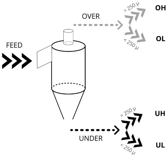
Figure 2.
Hydrocyclone system and the type of samples recovered in the two output streams (under (U), over (O). The mineral was then separated by sieving into two fractions with different particle sizes (higher (H) or lower (L) than 250 µm).
The samples were measured in reflection mode using copper radiation (from 4° to 120° with a 0.017° step size and 100 s integration time by step). The identification of the main mineral phases presents in the samples (celestine, strontianite, barite, Mg-calcite, dolomite, quartz, kaolinite, illite, paragonite) and the corresponding quantitative analysis of weight percentages were performed using the Rietveld method with TOPAS software v.5 (Bruker, Billerica, MA, USA).
3. Results and Discussion
3.1. Characterization of Dense Media
We characterized the stability and viscosity of the dense medium to better understand its behavior in our experimental hydrocyclone system. We also examined how to control and optimize the mineral separation process. The dense media should ideally have low viscosity and high stability [30,31]. Viscosity describes the resistance of a solid particle as it moves in the medium. Stability describes the degree of stratification of particles in the medium as well as the settling rate [32].
3.1.1. Stability of Dense Media
The stability of the suspensions was measured from the settling velocity using the method described in Section 2.3.2. Figure 3A shows how the height of the suspension changes as a function of time. The stability value is calculated from the slope of these curves. When comparing the plots for the different ferrosilicon suspensions (CG, F, C40), one can see how the stability of the media decreases (slope increases in absolute value) as the particle size increases. On the other hand, the suspension containing magnetite (FM; 33% magnetite) has a much slower settling rate than that of pure ferrosilicon (F, CG, C40). This indicates that the addition of magnetite (with more irregularly shaped particles) to the ferrosilicon (with more spherical particles) suspension increases its stability. Therefore, to increase or maintain the stability of the suspension, fine particle minerals (e.g., bentonite) should be added to the coarser heavy mineral to reduce the settling velocity of the media [33]. These results are consistent with those of other authors [33,34,35]. Thus, the FM mixture performs better than suspensions with only ferrosilicon. Additionally, the use of dispersants and/or magnetic dopants could be alternative ways to improve the stability of the suspension [33,36,37].
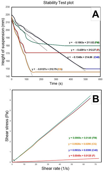
Figure 3.
Plots to determine the heavy mineral suspension stability and viscosity. (A) Distance of suspension versus time; (B) shear stress versus shear rate. CG (Course Grade), C40 (Cyclone 40), FM (mixture of ferrosilicon and magnetite), Fine (F).
3.1.2. Viscosity of Dense Media
To characterize the viscosity of the dense media, we considered it as a Newtonian fluid. We plotted the shear stress versus the shear rate to calculate the viscosity from the slope of these curves [38]. Figure 3B shows the shear curves of CG, C40, F and FM media for a constant density of 3.00 kg/L. In all cases, the slope is less than 1, indicating that the apparent viscosity decreases with the velocity profile and that the fluid behavior can be described as pseudoplastic (shear-thinning) [6,27,38].
The rheological properties of F medium show a more pseudoplastic nature and thus, a lower viscosity (0.049 Pa). Ferrosilicon media show similar rheological properties and a pseudoplastic nature (CG: 0.00928 Pa; C40: 0.0932 Pa; FM: 0.00969 Pa) [27].
When different media are compared at equal medium density, the F (ferrosilicon) medium has a lower viscosity than the FM medium (ferrosilicon and magnetite mixture). The increased viscosity of the FM medium can be attributed to the addition of magnetite, which produces a suspension containing irregularly shaped particles and a higher volume of solids (due to its lower density) [11,30].
Overall, our results show that the heavy mineral suspensions or media are quite unstable and settle rapidly, making it difficult to measure their viscosity [31]. The suspension behavior is closer to a pseudoplastic fluid, and its viscosity and stability depend on the mineral composition, particle size and shape. Optimal values of stability are achieved with solutions containing finer particles and the controlled addition of magnetite, which increases the stability of the suspension.
3.2. Celestine Mineral Concentration by DMS
3.2.1. Theoretical and Empirical Mass of Heavy Mineral in the Suspension
Table S7 shows the comparison between theoretical mass (according to Equations (2) and (3)) and empirical mass of the heavy mineral used to formulate the dense media in each experiment. Moreover, the table includes the over and under stream mass as well as the sampling time (t). In all tests, the calculated heavy mineral mass was greater than that required to achieve a 3.00 kg/L density medium. In the case of the FM medium, the theoretical and empirical masses were similar. In all tests, the theoretical heavy mineral mass was greater than that required to achieve a 3.00 kg/L medium. In the case of the FM medium, the theoretical and required masses were more similar. This may be related to the rheological properties of suspensions. Processes operating at high densities are vulnerable to viscosity changes as increasing the density of the medium would also increase its viscosity [39].
3.2.2. Mineral Mass Recovered in the Output Streams
The study of the mass obtained in each stream is essential for the design of post-hydrocyclone equipment at semi-industrial and industrial scales.
Figure 4 (Table S8) shows the mineral mass recovered in each output stream. The under streams (UL and UH) have a higher mass percentage in experiments using CG, F, FM, and FM_D media. However, the mineral mass recovered in the under and over streams is similar in the experiments using CG_D.
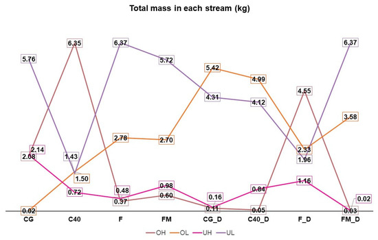
Figure 4.
Mineral mass recovered in the over and under streams for the different conditions tested.
The mineral mass recovered in the UH stream (containing the coarse (>250 µm) and more dense mineral particles) is highest in the CG, F, FM, and FM_D tests. As expected, desliming the run-of-mine mineral decreases the mineral mass in the OL stream (containing finer, <250 µm, and less dense mineral) and increases the mineral mass obtained in the output OH stream (except for the experiment using F medium).
3.3. Characterization of the Mineral by XRD
3.3.1. Characterization of Run-of-Mine Mineral Fed into the Input Stream
The XRD diagrams of the celestine mineral show that the main mineral phases detected in the run-of-mine mineral (sample 70) and mineral after desliming (sample 70D) (Table 1, Figure 5) are celestine, calcite, strontianite, quartz, dolomite, and illite. After desliming (70D), the celestine degree increases by a few percentage units (70: 67.45% celestine, 70D: 69.45% celestine) and the quartz content decreases (70: 6.79% quartz, 79_D: 3.54% quartz). The finer fraction of the mineral is enriched in quartz and clays; therefore, their selective removal through the desliming process should increase the percentage of celestine, as shown by Ariza-Rodriguez et al. (2022).

Table 1.
Mineral composition of the run-of-mine mineral samples (fed in the input stream) determined by XRD analysis.
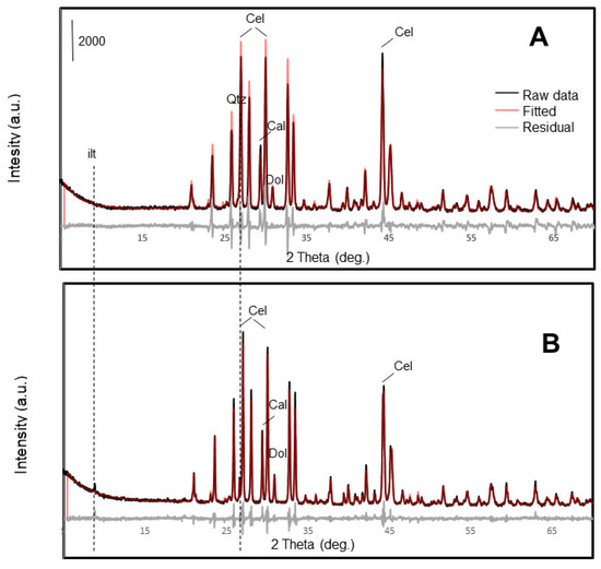
Figure 5.
X-ray diffraction patterns of 70D (deslimed; (A)) and 70 (run-on-mine; (B)) celestine mineral samples that were fed into the hydrocyclone system. Main peaks of mineral phases are indicated: illite (Ilt); celestine (Cel); calcite (Cal); and quartz (Qtz).
3.3.2. Characterization of the Mineral Composition in Output Streams
Figure 6, Figure 7, and Figure S6 and Table S9 show the main results obtained by XRD analysis. In particular, Figure 6 shows a comparison of the diffraction patterns of the mineral collected from the different output streams during the concentration process, starting with the 70 run-of-mine mineral and using C40 as dense medium (Figure S6 show results obtained with the same mineral after desliming 70D). It is evident that the characteristic peaks of celestine are always higher in the under stream, which has coarser particles UH. Figure 7 shows the mass percentages of the different mineral phases detected in the different output streams. In all cases, the stream with the higher celestine grade is the UH stream, the highest being the C40 medium, with or without desliming.
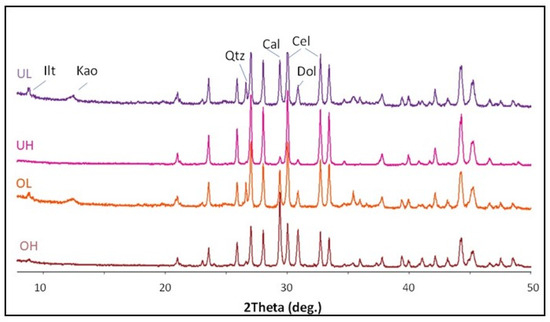
Figure 6.
Comparative XRD patterns of samples collected from the over (OH, OL) and under (UH, UL) streams with C40 dense medium that have a particle size higher (H) or lower (L) than 250 µm. Illite (Ilt); celestine (Cel); calcite (Cal); quartz (Qtz).
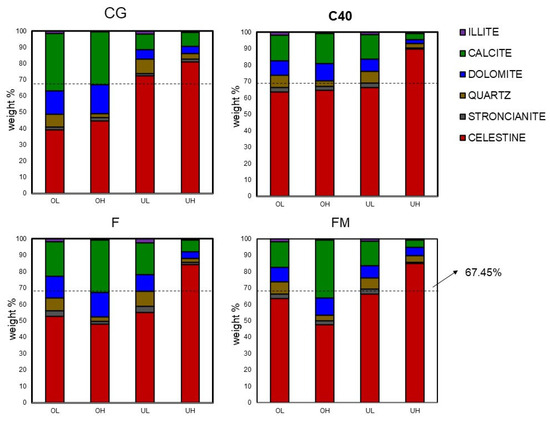
Figure 7.
Bar graphs showing the distribution of mineral phases in each output stream for each medium used in the experiments.
Even though celestine is concentrated and recovered mostly in the under streams (especially in the coarse size fraction UH), the main gangue mineral phase (calcite) appears in significant amounts in the under stream in the finer fraction mineral (UL). This is reasonable as calcite is associated with celestine in the run-of-mine mineral but has a finer particle size [2]. Calcite particles bound to heavier celestine crystals could be drawn into the under stream.
Figure 7 and Figure S6 show the distribution of the mineral phases present in the OL, OH, UL, and UH samples recovered after the concentration process. In the experiments using the CG medium, the mineral recovered from the under stream (UL and UH) has a significantly higher concentration of celestine than that recovered from the over stream. This demonstrates the efficiency of the density separation process and that heavier celestine particles are preferentially drawn into the underflow streams. For the other media suspension, the results are more variable. Nevertheless, in all cases, the highest concentration of celestine was obtained in the UH stream (under stream and larger particle size fraction, above 250 µm). In the experiments using the C40 dense medium, the percentage of celestine obtained in the over streams (OH and OL) and UL stream is very similar (differing by less than 2%) (OH: 63.51% celestine; OL: 64.64% celestine; UL: 66.36% celestine). When CG, F and FM media are used, the percentage of celestine in the OH and OL streams are lower than the corresponding percentages in the under streams.
Mineral desliming increases the concentration of celestine, especially in the OL stream, as demonstrated in Figure S6. Desliming exhibits significant beneficial results in some mine processing. It is considered a critical factor for yield and avoids the pulping process [40,41]. In this case, desliming increases the concentration of celestine in the over stream with smaller size fraction (OL). Other studies, which used flotation concentration methods, demonstrated the best way to increase mineral concentration was to remove the fines as they hinder sedimentation [42,43].
- Celestine concentration in the output streams
Figure 8 and Figure S7 show the concentration/percentage of celestine (main phase detected) for each output stream (over O or under U) with particle sizes higher (H) or lower (L) than 250 µm, without considering the total mineral mass recovered. The concentration of celestine is shown using a grey scale and the increasing celestine concentration is shown as a darker colour.
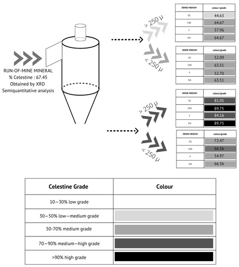
Figure 8.
Celestine concentration in the output streams starting from the run-of-mine mineral (without desliming; sample 70).
Without desliming, the highest percentage of celestine is obtained from the output stream with the larger particle size (UH) for the dense medium C40 and FM (Figure 8).
The highest celestine concentration is obtained in the UH stream with C40 (Figure S7) when desliming mineral is the starting material. He & Laskowski (1994) demonstrated that the separation efficiency of coarse particles (>2.0 mm) in a dense medium is determined by the stability of the medium (an increase in medium density results in better separation efficiency), whereas when the medium particles are finer (<0.5 mm), the rheological properties play a more important role. In this sense, opposite trends can be shown between separation efficiency and medium density. At high medium densities (>1.5 s.g.), the effect of medium rheology becomes dominant. In this study, the best results were obtained with C40 (82–90% < 45 µm), which has a viscosity similar to FM and CG, but is more stable.
Figure 9 shows the celestine mass recovered in each stream in the different experiments. The highest amount of celestine is recovered in the UH stream. This result is more evident for CG, F, and FM without desliming and in experiments using the FM_D medium. For the DMS process, the density of the mineral in heavy media should be at least twice the required medium density. For this reason, it would be better to use ferrosilicon (with a density of more than twice 3.00 kg/L) than magnetite [44]. However, these results coincide with the current study if the mineral is deslimed. At high medium densities (>1.50 kg/L), the effect of viscosity becomes dominant; it is beneficial in this density range to use coarse mediums to improve separation efficiency [45].
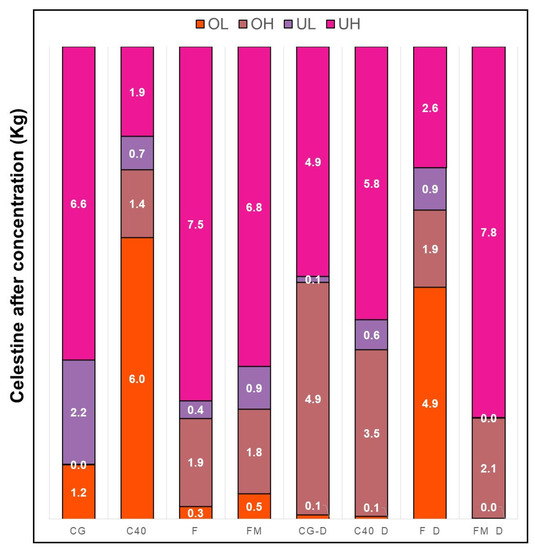
Figure 9.
Quantities of celestine recovered in the different output streams for the different media tested.
4. Conclusions
This study shows how medium-grade celestine mineral from Montevive can be efficiently concentrated using dense media separation (DSM) with a laboratory scale hydrocyclone system. The influence of relevant operation parameters such as conditioning celestine mineral, type of dense medium, and feed pressure were tested. These results could be used to scale up the process to a semi-industrial and industrial scale. This would enable the mine operation to become more sustainable and decrease its overall impact on the environment.
In the case of ferrosilicon media (CG, F, C40), the stability of the suspension increases as the grain size decreases. The addition of magnetite increases the stability of the suspension (FM) (even though magnetite has a larger particle size than ferrosilicon) due to their non-spherical shape. Moreover, dense media rheological and stability properties are highly variable and should be regularly monitored during the separation process.
The optimum results for the celestine mineral concentration experiments were obtained in the under stream for the coarse fraction of the mineral (>250 µm). If only considering the output under stream (UNDER), and the coarser (UH) and smaller (UL) size fractions, the optimum results (highest celestine mass recovered) were obtained using the run-of-mine mineral (without desliming) and CG, F, or FM media.
If examining the celestine concentration alone, the optimum results were obtained when the C40 medium was used, which recovered mineral with up to 90% celestine content. However, although the C40 medium achieves high concentrations of celestine, the output flow rates and the total mass of celestine recovered are low.
Further studies are needed to validate the parameters of dense medium density and hydrocyclone inlet pressure on a semi-industrial scale, as well as to study the hydrocyclone inclination parameters.
Supplementary Materials
The following supporting information can be downloaded at: https://www.mdpi.com/article/10.3390/app131810206/s1. Figure S1. Conditioning; Table S1. Interest elements content in FeSi; Figure S2. Stability test plot; Table S2. Physical properties of FeSi; Figure S3. Schedule of AMP test equipment; Table S3. Particle size of atomised FeSi; Figure S4. AMP Test equipment; Table S4. Element content in magnetite; Figure S5. Magnetic separator; Table S5. Particle size of magnetite DMS80; Figure S6. Bar Graph of mineral phases in each output stream: Table S6. Viscosity and stability of dense media applied; Figure S7. Setup schedule of celestine degree (run-on-mine): Table S7. Theorical and empirical weights; Table S8. Obtained mass of each stream; Table S9. XRD analysis and flow rate of output streams.
Author Contributions
N.A.-R., methodology, investigation, writing—original draft, writing—review and editing; A.B.R.-N., methodology, formal analysis, validation, writing—review and editing and funding acquisition; M.C.d.H., validation, writing—review and editing, supervision; M.J.M.-B., conceptualization, formal analysis, writing—review and editing, supervision and funding acquisition. All authors have read and agreed to the published version of the manuscript.
Funding
This research was funded by CNT 5589 (University of Granada) and MineTheGap (European Union) CELABDEN PROJECT.
Institutional Review Board Statement
Not applicable.
Informed Consent Statement
Not applicable.
Data Availability Statement
Not applicable.
Acknowledgments
Advanced Mineral Processing (AMP) provided images/schematic of the pilot plant to create Figure 1B.
Conflicts of Interest
The authors declare no conflict of interest.
References
- Jimeno, C.L.; González, C.M. Las materias primas minerales y la transición energética. Cuad. De Estrateg. 2022, 209, 61–174. [Google Scholar]
- Ariza-Rodríguez, N.; Rodríguez-Navarro, A.B.; Calero de Hoces, M.; Martin, J.M.; Muñoz-Batista, M.J. Chemical and Mineralogical Characterization of Montevive Celestine Mineral. Minerals 2022, 12, 1261. [Google Scholar] [CrossRef]
- García-Veigas, J.; Rosell, L.; Cendón, D.I.; Gibert, L.; Martín, J.M.; Torres-Ruiz, J.; Ortí, F. Large celestine orebodies formed by early-diagenetic replacement of gypsified stromatolites (Upper Miocene, Montevive-Escúzar deposit, Granada Basin, Spain). Ore Geol. Rev. 2015, 64, 187–199. [Google Scholar] [CrossRef]
- Martin, J.M.; Ortega Huertas, M.; Torres Ruiz, J. Genesis and Evolution of Strontium Deposits of the Granada Basin (Southeastern Spain)—Evidence of Diagenetic Replacement of a Stromatolite Belt. Sediment. Geol. 1984, 39, 281–298. [Google Scholar] [CrossRef]
- Aslan, N.; Canbazoglu, M. Processing of Thinkener Underflow from Celestite Concentrator by Multi Gravity Separator. Ph.D. Thesis, Cumhuriyet University, Department of Mining Engineering, Sivas, Turkey, 1996. [Google Scholar]
- Bosman, J. The art and science of dense medium selection. J. South. Afr. Inst. Min. Metall. 2014, 114, 529–536. [Google Scholar]
- Caner Orhan, E.; Can, M.; Olgun, Z.; Özer, A. Performance Evaluation Practices at Dense Medium Separation Circuits.; Litvinenko, V., Ed.; Springer International Publishing: Cham, Switzerland, 2016; pp. 839–847. [Google Scholar]
- De Korte, G.J.; Engelbrecht, J. Dense Medium Cyclones. Int. J. Coal Prep. Util. 2014, 34, 49–58. [Google Scholar] [CrossRef]
- Gupta, A.; Yan, D. Mineral Processing Design and Operations, 2nd ed.; Elsevier: Amsterdam, The Netherlands, 2016; Available online: http://www.sciencedirect.com/science/article/pii/B9780444635891000277 (accessed on 19 April 2023).
- Ma, G.; Bu, X.; Xie, G.; Peng, Y.; Sha, J.; Xia, W.; Wu, E. Comparative Study of Separation Performance of a Spiral and Dense-medium Cyclone on Cleaning Coal. Int. J. Coal Prep. Util. 2021, 41, 108–116. [Google Scholar] [CrossRef]
- Napier-Munn, T. The dense medium cyclone—Past, present and future. Miner. Eng. 2018, 116, 107–113. [Google Scholar] [CrossRef]
- Silva, A.C.; Schons Silva, E.M.; Vieira Matos, J.D. Hydrocyclones simulation using a new modification in Plitt’s equation. IFAC Proc. Vol. 2013, 46, 12–17. [Google Scholar] [CrossRef]
- Umucu, Y. Investigation of separation performance of dense medium cyclone using computer simulation. Physicochem. Probl. Miner. Process. 2015, 51, 303–314. [Google Scholar] [CrossRef]
- Vakamalla, T.; Narasimha, M. Rheology-based CFD modeling of magnetite medium segregation in a dense medium cyclone. Powder Technol. 2015, 277, 275–286. [Google Scholar] [CrossRef]
- Wills, B.A.; Finch, J.A. Dense Medium Separation (DMS). In Wills’ Mineral Processing Technology, 8th ed.; Butterworth-Heinemann: Boston, MA, USA, 2016; 20p. [Google Scholar]
- Hernáinz, F.; Calero, M. The effect of the degree of grinding on the flotation of celestite ore. Adv. Powder Technol. 2001, 12, 481–491. [Google Scholar] [CrossRef]
- Ozkan, A.; Uebeyiay, H. Selective flocculation of celestite from celestite-calcite fines. Indian J. Chem. Technol. 2008, 15, 383–387. [Google Scholar]
- Cebeci, Y.; Ulusoy, U.; Erişen., M. Concentration of Celestite by Oil Agglomeration. In Proceedings of the 8th International Mineral Processing Symposium, Antalya, Turkey, 16–18 October 2000. [Google Scholar]
- Cebeci, Y.; Sönmez, İ. Investigation of spherical oil agglomeration properties of celestite. J. Colloid Interface Sci. 2004, 273, 198–204. Available online: https://www.sciencedirect.com/science/article/pii/S0021979703011391 (accessed on 1 May 2023). [CrossRef] [PubMed]
- Izerdem, D.; Orhan, E.C.; Ozcan, O.; Alpay, E. Application of density tracers in a dense medium circuit: A case study. Miner. Eng. 2018, 121, 39–46. [Google Scholar] [CrossRef]
- Magwai, M.K.; Bosman, J. The effect of cyclone geometry and operating conditions on spigot capacity of dense medium cyclones. Int. J. Miner. Process. 2008, 86, 94–103. [Google Scholar] [CrossRef]
- Marion, C.; Williams, H.; Langlois, R.; Kokkilic, O.; Coelho, F.; Awais, M.; Rowson, N.A.; Waters, K.E. The potential for dense medium separation of mineral fines using a laboratory Falcon Concentrator. Miner. Eng. 2017, 105, 7–9. [Google Scholar] [CrossRef][Green Version]
- Aktaş, Z.; Karacan, F.; Olcay, A. Centrifugal float–sink separation of fine Turkish coals in dense media. Fuel Process. Technol. 1998, 55, 235–250. [Google Scholar] [CrossRef]
- Klima, M.; Xu, D.; Cho, H. A Preliminary Investigation of Dense-Medium Centrifugation for Fine Coal Separations. In Metallurgy, and Exploration; Society for Mining: San Francisco, CA, USA, 1995; pp. 138–142. [Google Scholar]
- Rao, T.C.; Barnwal, J.P.; Govindarajan, B. Studies on a Vorsyl separator as an alternate for a dense medium cyclone. Int. J. Miner. Process. 1998, 53, 49–57. [Google Scholar] [CrossRef]
- Dou, D.; Zhou, D.; Yang, J. A new partition curve model of dense-medium cyclone based on process parameters. Int. J. Coal Prep. Util. 2020, 40, 459–472. [Google Scholar] [CrossRef]
- Shi, F. Determination of ferrosilicon medium rheology and stability. Miner. Eng. 2016, 98, 60–70. [Google Scholar] [CrossRef]
- Shi, F.N.; Napier-Munn, T. A model for slurry rheology. Int. J. Miner. Process. 1996, 47, 103–123. [Google Scholar] [CrossRef]
- Eriez. Available online: https://www.eriez.com/ (accessed on 22 November 2022).
- Geer, M.R.; Sokaski, M.; West, J.M.; Yancey, H.F. The Role of Viscosity in Dense-Medium Coal Cleaning; United States Department of the Interior, Bureau of Mines: Washington, DA, USA, 1957; Volume 5354. [Google Scholar]
- Klein, B. Rheology and Stability of Magnetite Dense Media. 1992. Available online: https://open.library.ubc.ca/collections/831/items/1.0081158 (accessed on 1 May 2023).
- Barnes, H.A.; Hutton, J.F.; Walters, K. (Eds.) Chapter 7—Rheology of Suspensions. In Rheology Series; Elsevier: Amsterdam, The Netherlands, 1989; Volume 3, pp. 115–139. Available online: https://www.sciencedirect.com/science/article/pii/B9780444874696500111 (accessed on 1 May 2023).
- Mabuza, N.T.; Pocock, J.; Loveday, B.K. The use of surface active chemicals in heavy medium viscosity reduction. Miner. Eng. 2005, 18, 25–31. Available online: https://www.sciencedirect.com/science/article/pii/S0892687504002183 (accessed on 1 May 2023). [CrossRef]
- Kirchberg, S.; Abdin, Y.; Ziegmann, G. Influence of particle shape and size on the wetting behavior of soft magnetic micropowders. Powder Technol. 2011, 207, 311–317. [Google Scholar] [CrossRef]
- Collins, B.; Napier-Munn, T.J.; Sciarone, M. The production, properties, and selection of ferrosilicon powders for heavy-medium separation. J. South. Afr. Inst. Min. Metall. 1974, 75, 103–115. [Google Scholar]
- Appel, I.; Behrens, S. Influence of the particle parameters on the stability of magnetic dopants in a ferrolyotropic suspension. J. Magn. Magn. Mater. 2017, 431, 49–53. [Google Scholar] [CrossRef]
- López-López, M.; Iglesias, G.; Durán, J.; González-Caballero, F. On the Stability of Magnetic Colloids. 2008, 63, 31–46. Available online: http://annales.umcs.lublin.pl/tt_p.php?rok=2008&tom=63&;sectio=AA&;numer_artykulu=04&;zeszyt=0 (accessed on 1 May 2023).
- Norton, I.T.; Spyropoulos, F.; Cox, P. (Eds.) Viscosity and Oscillatory Rheology; Wiley: Hoboken, NJ, USA, 2010; pp. 7–28. [Google Scholar] [CrossRef]
- Napier-Munn, T.; Scott, I.A. The effect of demagnetisation and ore contamination on the viscosity of the medium in a dense medium cyclone plant. Miner. Eng. 1990, 3, 607–613. [Google Scholar] [CrossRef]
- Menéndez, M.; Gent, M.; Toraño, J.; Diego, I. Optimization of multigravity separation for recovery of ultrafine coal. Min. Metall. Explor. 2007, 24, 253–263. [Google Scholar] [CrossRef]
- Yang, X.; Yang, G.; Liu, P.; Li, X.; Jiang, L.; Zhang, J. Study on the Desliming Performance of a Novel Hydrocyclone Sand Washer. Separations 2022, 9, 74. [Google Scholar] [CrossRef]
- Oats, W.J.; Ozdemir, O.; Nguyen, A.V. Effect of mechanical and chemical clay removals by hydrocyclone and dispersants on coal flotation. Miner. Eng. 2010, 23, 413–419. [Google Scholar] [CrossRef]
- Tao, Y.J.; Zhao, Y.N.; Xian, Y.S.; Song, A.; Wang, Y.P.; Shi, Z.X. Coal Desliming Using Annular Rinse Water Hydrocyclone; Trans Tech Publ.: Stafa-Zurich, Switzerland, 2020; pp. 28–40. [Google Scholar]
- Gajda, D.; Lutyński, M.; Kujawska, M. Substitution of Magnetite in Dense Medium Separation by Zinc-Lead Waste; IOP Publishing: London, UK, 2018; p. 012036. [Google Scholar]
- He, Y.B.; Laskowski, J.S. Effect of dense medium properties on the separation performance of a dense medium cyclone. Miner. Eng. 1994, 7, 209–221. [Google Scholar] [CrossRef]


Disclaimer/Publisher’s Note: The statements, opinions and data contained in all publications are solely those of the individual author(s) and contributor(s) and not of MDPI and/or the editor(s). MDPI and/or the editor(s) disclaim responsibility for any injury to people or property resulting from any ideas, methods, instructions or products referred to in the content. |
© 2023 by the authors. Licensee MDPI, Basel, Switzerland. This article is an open access article distributed under the terms and conditions of the Creative Commons Attribution (CC BY) license (https://creativecommons.org/licenses/by/4.0/).