Article

A Simplified Mechanical Model and Analysis for the Settlement Deformation of Buried Pipelines Caused by Open-Cut Excavation

1
School of Civil Engineering, Institute of Disaster Prevention, Beijing 101601, China
2
Key Laboratory of Building Collapse Mechanism and Disaster Prevention, China Earthquake Administration, Beijing 101601, China
3
School of Geological Engineering, Institute of Disaster Prevention, Beijing 101601, China
*
Author to whom correspondence should be addressed.
Appl. Sci. 2023, 13(18), 10356; https://doi.org/10.3390/app131810356
Submission received: 27 July 2023 / Revised: 26 August 2023 / Accepted: 30 August 2023 / Published: 15 September 2023
(This article belongs to the Section Civil Engineering)

Abstract

:
This study aims to reveal the deformation characteristics of buried pipelines and the effects of various parameters on settlement displacement using the analytical analysis method. A simplified mechanical model for the settlement displacement of buried pipelines is proposed with the theory of the Winkler model, and the sensitivity impacts of various parameters are performed by comparing them with those given by other cases. The rationality of the proposed approach is verified by a comparison with previous cases, and it also turned out that the present method performed better than the other two methods in the literature in its overall tendency of settlement displacement and error precision. The parameter analysis results of this study indicate that the maximum settlement displacement of the buried pipelines only increases linearly with the increase in ground displacement. Other parameters such as the subgrade modulus and calculated length increase to a certain threshold; the maximum settlement displacement will remain stable. However, the diameter and elastic modulus of the pipelines only have a small effect on the maximum settlement displacement of the pipelines, so they are not a sensitive factor and these effects can be ignored. In addition, an engineering example of pipeline deformation in a deep foundation pit from open-cut excavation is researched to verify the practicality of this present method.

1. Introduction

The distribution of buried pipeline networks in cities is very complex, and includes a large-scale lifeline system. The excavation of a foundation pit may lead to a large deformation of adjacent pipelines, and, in several cases, even lead to water and gas leakage. Once this happens, the urban lifeline will be under serious threat, causing a great loss of lives and property. Therefore, research on the settlement deformation of nearby buried pipelines affected by deep excavation is an important work with regard to foundation pits [1,2,3].
So far, the analysis methods for the settlement deformation of buried pipelines mainly include the theoretical analysis method, numerical simulation method, model experiment method, and field test method [4]. However, in the past, because very limited data regarding excavation-induced buried pipeline deformation are available for analysis, as a consequence, the study of the settlement displacement of buried pipelines still relies heavily on theoretical analysis and numerical simulation. For the past several decades, several researchers have tried to establish a strict mechanical model for obtaining an analytical solution to buried pipeline deformation in order to evaluate the safety of pipelines [2,3,4,5]. At present, theoretical analysis methods primarily rely on two mechanical models, one of which is the Winkler model, and the other is the Pasternak model [6]. Peck [7] proposed a theoretical formula forecasting the ground surface caused by tunnel excavation based on a larger number of field test data, and provided a reference for the deformation theory of buried pipelines. After, under the framework of the Winkler model, some analytical solutions for buried pipeline deformation based on the different boundary conditions and load conditions were researched by different scholars, such as Yu et al., Gong et al., and Jiang et al., who have been developing simplified calculated models and analyzing different influence factors on settlement displacement [3,8,9]. The Winkler model is mostly used in the above research, but this model ignores the shear stress in the soil and cannot describe the continuity of soil deformation very well.
To overcome these shortcomings, in recent years, He et al., Zhao et al., and Zhu et al. used the Pasternak model to derive the calculated mechanics model of pipe–soil separation, and also proposed a new analysis method for buried pipeline deformation by excavation [10,11,12]. Lin et al. [13] also proposed an analytical solution for the response of two neighboring pipelines to tunneling based on the Pasternak model, which not only spreads the analysis method to a wider extent, but also enriches the evaluation methods for pipeline safety. In the above research works, a prominent problem is the lack of empirical analysis. These methods mainly focus on theoretical analysis, less on empirical analysis, and the empirical analysis of the data is also not enough. As a result, the accuracy of these methods is limited, which also limits their popularization and application.
Another common research method in buried pipeline settlement deformation is numerical simulation, including the finite element method, finite difference method, and discrete element method. Previously, Crofts et al. [14] proposed a principle of horizontal movement caused by shallow buried pipelines during excavation and backfilling, and established an elasticity mechanical model to analyze the mechanical state of buried pipelines. Dong et al. [15] used the finite element method to investigate the settlements of nearby buildings and buried pipelines induced by excavation, focusing particularly on the influence factors of settlement. Zhang et al. [16] studied the mechanical behavior analysis of a buried pipeline underground overload, using a general-purpose finite element programmer. Zhang et al. [17] also investigated the settlement of pipelines induced by tunneling based on the ABAQUS program, analyzing each influence parameter’s sensitivity to the settlement displacement. Song et al. [18] researched the impact of deep foundation pit excavation on the adjacent oil pipelines using the finite element software MIDAS and a field test. In addition, Jiao et al. [4] also used PLAXIS 3D software to numerically analyze the settlement and deformation of pipelines in soil rock composite stratum, revealing some characteristics of pipeline deformation induced by excavation. Alshboulet al. and Almasabhaet al. put forward a method to optimize the structural performance of buried reinforced concrete pipelines in cohesionless soils by using the finite element method [19,20]; Uribe-Henao et al. [21] developed an advanced numerical model to account for building–soil excavation interactions, and provided a new consideration for the deformation theory of adjacent buried pipelines. However, these methods are only for circular cross-sections, usually disregarding non-circular cross-sections of pipelines and their relative position to the foundation pit, which terribly limits its scope of application. In fact, irregularly shaped foundation pits are widely found in urban construction, and similar complex problems are unavoidable.
A centrifuge test is an innovative experiment method which is conducted to study the mechanical behavior of buried pipelines, but there are few reports on the open-cut excavation of the foundation pit [22]. Because of the difficulty in determining the excavation and its effects on buried pipelines, the experimental model problem is extremely complex and difficult to accurately build. On the other hand, experimental testing is considered uneconomical and impractical for measuring the performance of pipelines under a high soil fill depth [19]. In light of the above problems, some researchers attempt to establish a model based on field test data, such as Liu et al. and Liu et al. [23,24]. Tan et al. [25] developed empirical formulae for estimating the horizontal and vertical displacement of shallowly buried pipelines caused by adjacent excavation based upon regression analyses on the amounts of field measurements in Shanghai soft ground. Zhang et al. [26] also used a large number of measured data to analyze the characteristics of surface settlement and deformation of a foundation pit in Beijing, and su mmarized the law of the surface subsidence and gave empirical parameters of predicted deformation. Guo et al. [27] analyzed the performance of shallowly buried pressurized pipelines based on the extensive field performance data collected by means of settlement points and inclinometers located within and adjacent to the excavation. Yang et al. [28] investigated the performance of a deep foundation pit excavation and its influence on adjacent piles through the results of field measurements, and the result agreed well with the empirical prediction in mixed ground. The current empirical formulae fitted by the field test data have some advantages, but some limitations also exist. These study cases mentioned above can only represent the individual, so the results do not have universality.
The purpose of this study is to supply a simple and practical calculated method of buried pipeline settlement deformation, and provide services for pipeline safety evaluation during the construction period. What distinguishes this study the most from the previous solutions is the consideration of the working condition where the pipelines are not parallel to the edge of foundation pit, and the pipelines of a non-circular cross-section are also considered emphatically. A simplified mechanical model for the settlement deformation of buried pipelines and analytical solution is verified by two cases in the literature, and the sensitivity impact of various parameters on the settlement displacement is also discussed more in-depth. Finally, an engineering example is introduced to test the practicability of the present method.

2. Simplified Mechanical Model

In view of the Winkler theory, the deformation of buried pipelines can be divided into two parts. Part of it is caused by the original loads, and part of it is caused by the excavation. Original loads acting on the pipelines include weight and overburden pressure. According to the measured data, it is found that the deformation of the buried pipeline during the excavation is a curve. The characteristic of deformation along the pipeline axis direction is large in the middle and weak at the end. Figure 1 presents photos of a typical pipeline failure case which was caused by an adjacent deep excavation [25].

2.1. Analytical Model

Based on the analysis of the deformation phenomenon of buried pipelines, the deformation of pipelines is suggested to be divided into two regions: subsidence area and non-subsidence area. A simplified mechanical model of pipelines is developed, and is shown in Figure 2. This simplified model involves an assumption that the deformation of pipelines occurs in the subsidence area and no deformation of pipelines occurs in the non-subsidence area.
For the length range of the subsidence area, some researchers provide the reference basis, which is generally taken as twice the longitudinal length of the foundation pit [29]. Liu et al. [30] proposed that the relationship between the length of the outmost boundary of the subsidence area and the height of the retaining wall, mathematically, is
z 0 = H g tan 45 φ 2
where, z0 is the length of outmost boundary of the subsidence area, m; Hg is the height of retaining wall, m; φ is the average value of the internal friction angle of soil, °.
The Gaussian normal distribution function can be described as the ground settlement curve by the underground excavation in earlier studies, but the process of calculation is very complicated and slow, which is not suitable for practical application. Under ideal conditions, the settlement of pipelines is distributed symmetrically from the center to both ends, with the characteristics of a mathematical even function. It is widely known that one of the advantages of trigonometric functions is that they have simple controlled parameters. Thus, to simplify the complex calculation above for portable engineering application, a proximate calculation method is proposed, which innovatively uses the trigonometric function to instead express the Gaussian normal distribution function. The soil displacement curve y(x) can be expressed as
y ( x ) = A cos ω x + α 0
where, A is the amplitude of the settlement displacement curve, m; ω and α0 are undetermined coefficients.
In this study, assume that the ground settlement corresponding to the center of the pipeline is δ, and the boundary between the subsidence area and the non-subsidence area is defined as full fixed. The boundary conditions can be expressed as
x = 0 ,     y = δ x = l ,      y = 0 x = l ,      y = 0
Thus, the solution of three undetermined coefficients in Equation (2) can be, respectively, written as follows:
A = δ α 0 = 0 ω = π / 2 l
Then, Equation (2) is given by
y ( x ) = δ cos π 2 l x
During the excavation, the key reason for the vertical displacement of the buried pipelines is the ground soil disturbance that causes the pipelines’ settlement. The Winkler model assumes that the pressure intensity at any point on the surface of the foundation is directly proportional to the settlement, and there is no doubt that the analytical method based on this model is a suitable choice [30]. Thus, the deformation of buried pipelines nearby the foundation pit is calculated using the Winkler model; the differential equation for the deflection of buried pipelines can be expressed as
E I d 4 w x d x 4 = k D w x + k D δ cos π 2 l x
where, w(x) is vertical displacement equation of pipelines caused by adjacent excavation, m; k is subgrade modulus, kN/m3; D is the outer diameter of pipelines, m; EI is the bending stiffness of pipelines, kN·m2.
Equation (4) can be solved by using the initial parameters method. Then, the solution of Equation (4) is divided into two parts: one part is the general solution of vertical displacement; the other is the correction term of vertical displacement. The correction term can be written as
f ( x ) = k D δ E I β 3 0 x ϕ 4 β x z cos π 2 l z d z    = k D δ E I β 3 1 4 β cos π 2 l x 1 4 β ϕ 1 β x + π 2 4 l 2 1 4 β 3 ϕ 3 β x 1 + π 4 16 l 4 1 4 β 4
Thus, the equation for the deflection of buried pipelines is given by
w x = f x + w 0 ϕ 1 β x + θ 0 1 β ϕ 2 β x M 0 1 E I β 2 ϕ 3 β x Q 0 1 E I β 3 ϕ 4 β x
where, β = k D 4 E I 4 , ϕ1(βx), ϕ2(βx), ϕ3(βx), and ϕ4(βx) are Krylov functions; w0 is the vertical displacement of the pipeline center, m; θ0 is the rotation angle of the pipeline center, rad; M0 is the bending moment of the pipeline center, kN·m; Q0 is the shear force of the pipeline center, kN.

2.2. Boundary Conditions and Coefficients

The equation for the deflection of buried pipelines in the present study has a symmetry; thus, in the calculated interval of −l to l, the maximum bending moment and deflection occur at the position of x = 0. It can also be concluded that the shear force and rotation angle at this location are zero, as
x = 0 ,     θ 0 = 0 x = 0 ,     Q 0 = 0
From this, the deflection equation of buried pipelines can be simplified as
w x = f x + w 0 ϕ 1 β x M 0 1 E I β 2 ϕ 3 β x
By deriving Equation (7), it can be obtained that the rotation angle equation of buried pipelines is
θ x = f x 4 β w 0 ϕ 4 β x M 0 1 E I β ϕ 2 β x
In this present study, the displacement of buried pipelines occurs only in subsidence areas, and there is no deformation in the non-subsidence area. So, at the connection of subsidence areas and non-subsidence areas, the boundary condition can be regarded as a fixed end restraint. It means that the deflection and rotation angle of pipelines are zero at the position of x = l, and the boundary condition is as follows:
x = l ,     w l = 0 x = l ,     θ l = 0
Thus, by substituting the boundary condition into Equations (7) and (8), w0 and M0 can be derived:
w 0 = k D δ 1 + π 4 16 l 4 1 4 β 4 π 2 4 l 2 1 4 β 2 ϕ 2 β l + ϕ 4 β l π 2 l 1 4 β β 2 ϕ 2 β l π 2 4 l 2 1 4 β 3 ϕ 3 β l 1 4 β ϕ 1 β l β ϕ 3 β l     / E I β 2 ϕ 1 β l ϕ 3 β l + 4 ϕ 4 β l ϕ 2 β l
M 0 = k D δ E I β 3 1 1 + π 4 16 l 4 1 4 β 4 π 2 4 l 2 1 4 β 3 ϕ 3 β l 1 4 β ϕ 1 β l ϕ 1 β l + π 2 4 l 2 1 4 β 2 ϕ 2 β l + ϕ 4 β l π 2 l 1 4 β 4 β ϕ 4 β l    / 1 E I β 2 ϕ 3 β l ϕ 1 β l + ϕ 2 β l 4 ϕ 4 β l
Substitute the initial parameters of w0 and M0 into Equation (7), and the specific form of the pipeline deflection equation can be obtained. It is obvious that an explicit solution to the settlement of buried pipelines using the above method is obtained, which can be solved by simple programming.

3. Examples

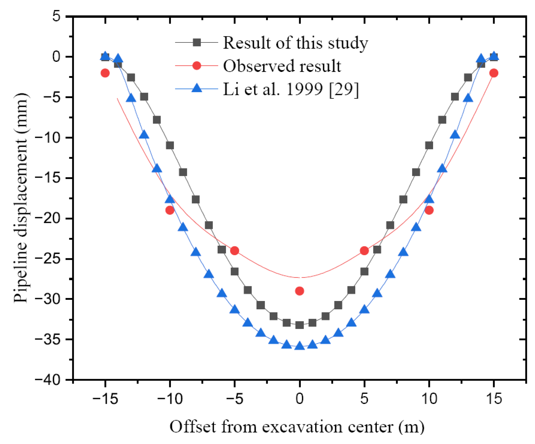
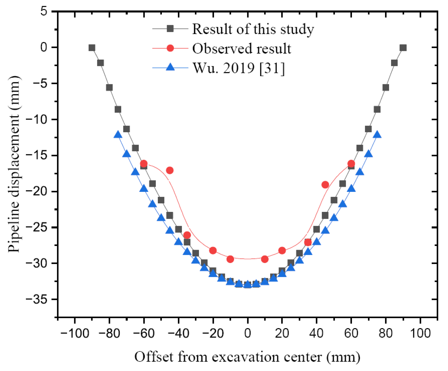
3.1. Verification of the Present Formulation

In order to verify the rationality of the analytical method proposed in this study, the settlement displacement of buried pipelines of two cases calculated using this approach is compared with the results reported in Li et al. and Wu’s studies based on different methods.
Case #1: Li et al. [29] presented the influences of a buried pipeline caused by a foundation pit excavation, based on the Winkler theory. This case is a 8.8 m deep excavation, which is surrounded by water pipelines, and buried 2 m below the ground surface. The pipeline consists of concrete, and the length from the axis of pipeline to the edge of foundation pit is 2.3 m. The outer diameter of the pipeline is 2000 mm, and the inner diameter is 1680 mm. There are seven settlement observation points on the pipeline, and the interval between two points is 5 m. Based on prospecting data, the value of the subgrade modulus is k = 10,000 kN/m3.
According to this present method, the distance from the center of water pipeline to the end of the observation point is 15 m, so the value of pipeline length is l = 15 m. The bending stiffness of the water pipeline calculated as follows:
E I = 3 × 10 10 × π D 4 d 4 64 = 3 × 10 10 × 3.14 × 2 4 1.68 4 64 = 11.83 × 10 9 N m 2
Therefore, the initial parameters can be derived as w0 = 33.22 mm, M0 = 5789.13 kN·m. Figure 3 shows that the vertical displacement of the pipeline is induced by foundation pit excavation, which is obtained by different methods. It can be seen that the vertical displacement calculated using the present method is basically close to the observed data. The calculated result proposed by Li et al. is also shown in Figure 3. From the above figure, it can be seen that the curve shapes of the calculated vertical displacements of this study are, in general, consistent with the result of the method proposed by Li et al., though there are slight differences between the two results. The maximum settlement displacement is one of the key indexes of pipeline deformation, and it is always concentrated on by the researchers. The observed maximum displacement of the pipeline center is about 29 mm, and it is smaller than the result calculated in this study, and the relative error is about 12.71%. Compared with the result calculated by Li et al., it can be found that the relative error is about 15.2%. Moreover, the results also show that the accuracy of using the method of this study is better than when using the method proposed by Li et al.
Case #2: Wu. [31] provided another example; the plane figure of foundation pit is rectangular-shaped, and the edge lengths are, respectively, 166 m and 50 m. This case is a 25.3 m deep excavation, which is surrounded by gas pipelines, and is buried 1.3 m below the ground surface. The outer diameter of the gas pipeline is 500 mm, and the wall thickness is 4 mm. The pipeline consists of steel, and the length from the axis of the pipeline to the edge of the foundation pit is 10.5 m. The elastic modulus of the steel pipe is E = 200 GPa, and the Poisson’s ratio is μ = 0.3. The foundation pit is excavated in the sand soil, with an elastic modulus E = 200 MPa and a Poisson’s ratio of μ = 0.3. The other soil material parameters are as follows: the unit weight of soil is γ = 18 kN/m3, the cohesion of soil is c = 2 kPa, and the internal friction angle of soil is φ = 18°. The value of the subgrade modulus is k = 10,000 kN/m3.
According to this present method, the distance from the center of the water pipeline to the end of the observation point is 90 m, so the value of the pipeline length is l = 90 m. The gas pipe is considered as a thin-walled steel pipe, so the bending stiffness of the gas pipeline is calculated as follows:
E I = 200 × 10 9 × π r 3 δ = 200 × 10 9 × 3.14 × 0.25 3 × 0.004 = 39.25 × 10 6 N m 2
Analytical results show that with this calculation method, the initial parameters can be calculated as w0 = 32.99 mm, M0 = 394.15 kN·m. When comparing the distribution laws of settlement displacement between the observed data, data of the literature, and data of this method, the result is basically accordant, as shown in Figure 4. According to the error analysis, it can be seen that the maximal error of vertical displacement compared with the observed result is 11.99%, and the precision is higher than that of the method proposed by Wu. The maximum error value in the literature is 18.0%. Moreover, the settlement displacement curve shape calculated using this method is more close to the observed values.
In the above two cases, it can be seen that the relative error between the calculation results of the method proposed in this study and observed data is better than the results in the literature, which proves that the above mentioned method is scientific and reasonable. Although the settlement displacement formulae are established by Li et al. and Wu, respectively, using the Winkler model and the Pasternak model, the mathematical solution has not been concise yet as the expression of the solution is too complicated. By using the trigonometric functions simulated the ground settlement curve, the analytic solution can be expressed as an integral form with simple controlled parameters, and the former complicated expression can be avoided. Additionally, it also made this method advance onestep toward that used in engineering. It is noteworthy that due to the influences of observed point location, monitoring equipment, and construction disturbances on the measured data, there is still a certain error, but the overall consistency is good. Therefore, all the above mentioned results also show that the analytical method proposed in this study can be used to perform the settlement displacement prediction of buried pipelines in order to determine a reasonable construction plan and provide technical guidance.
The calculating formula proposed in this study is suitable for the continuous and regular foundation pit, and for the condition that pipelines are mainly dominated by elastic deformation. Thus, it also can be regarded as a general formula for the deformation analysis of buried pipelines.

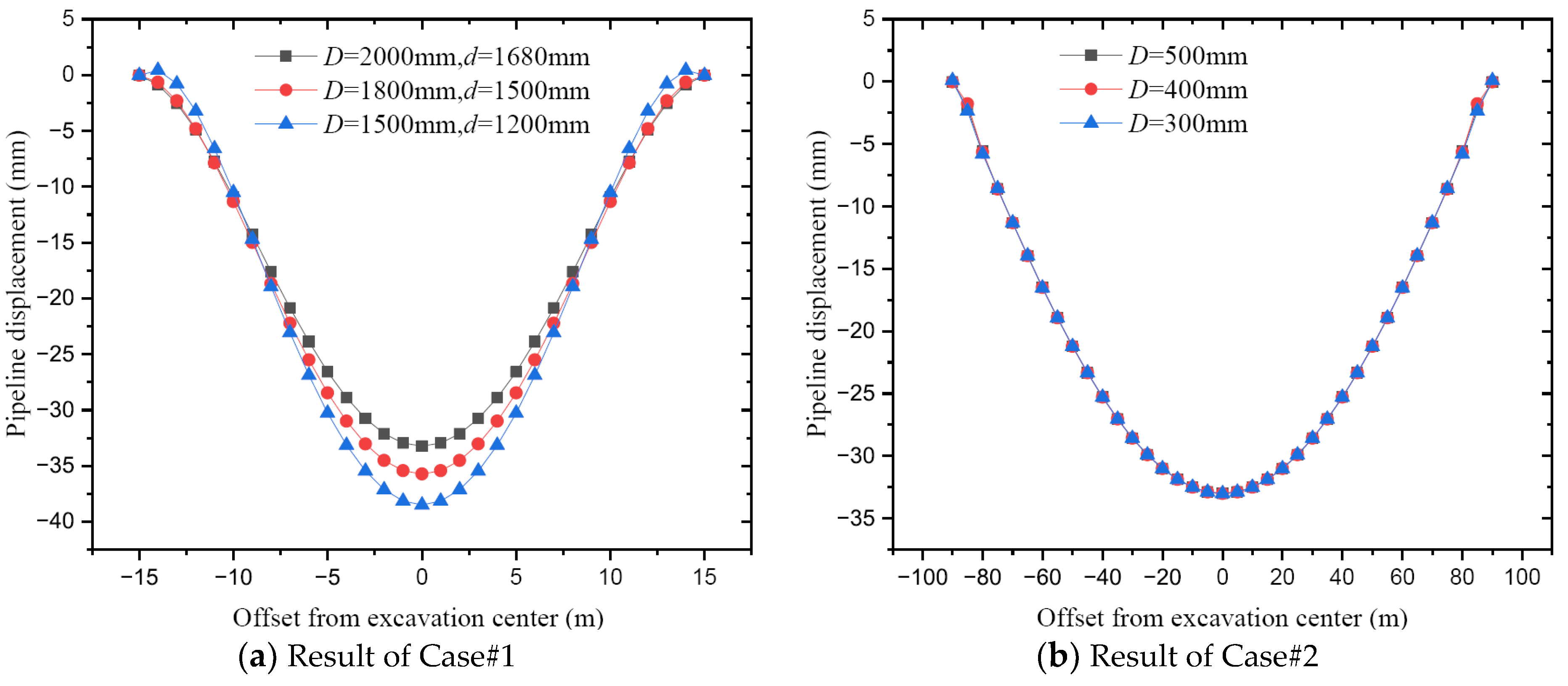
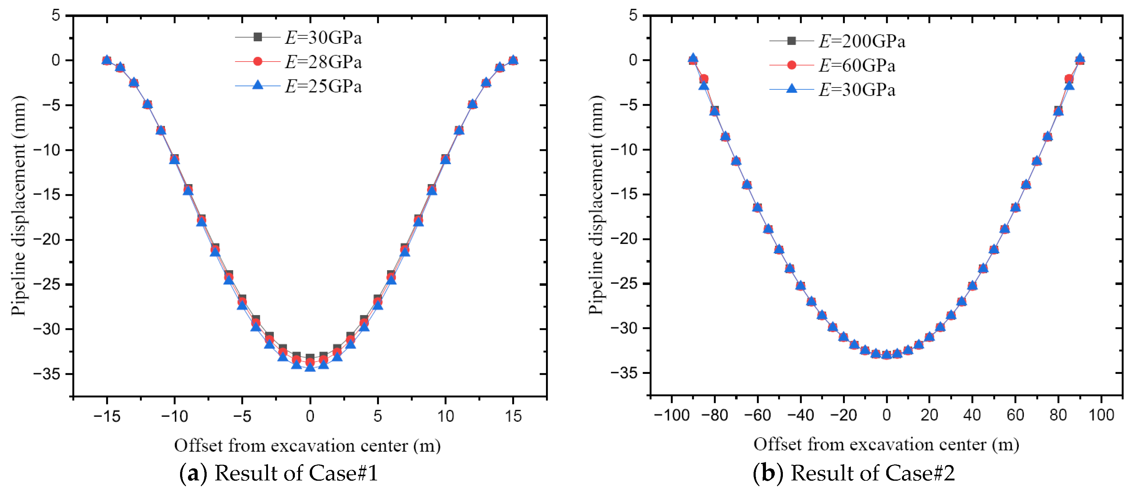
3.2. The Effects of Calculated Parameters on Results

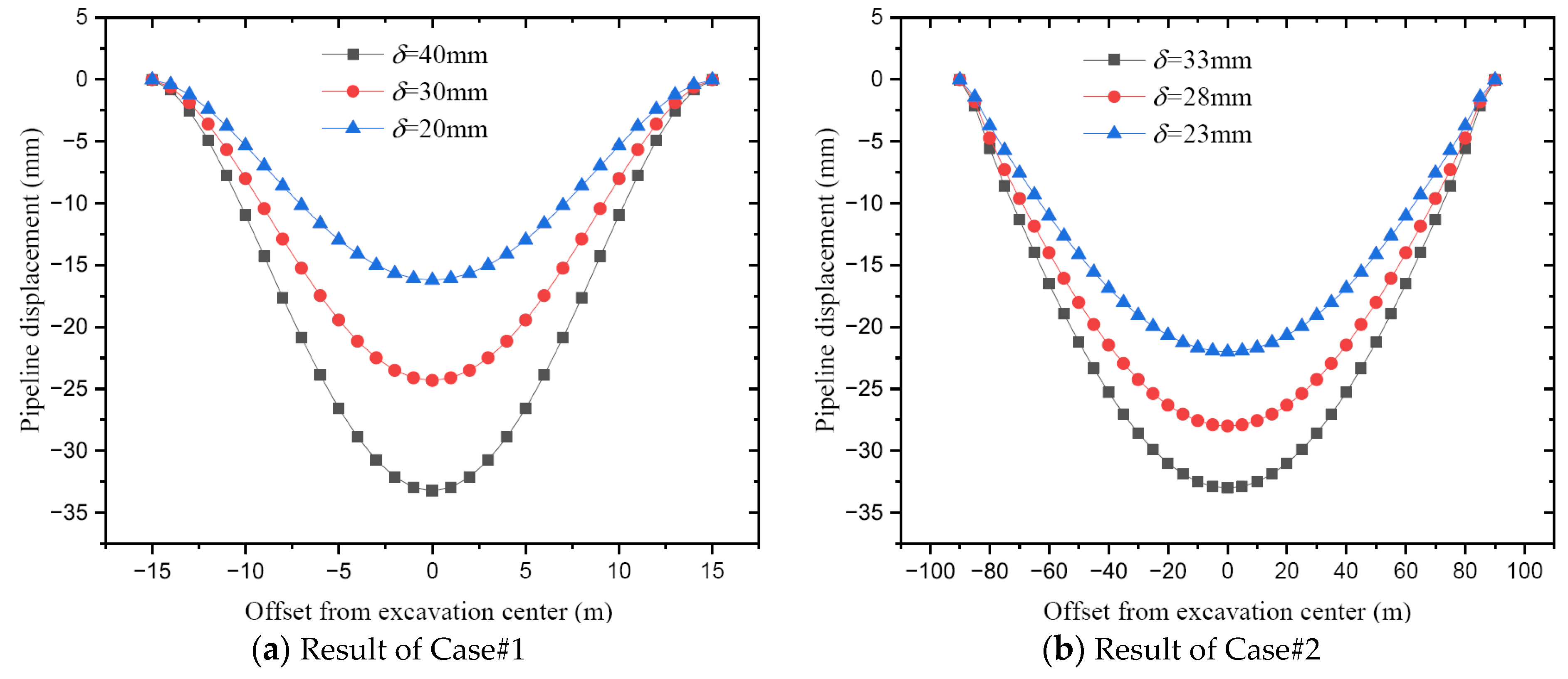
3.2.1. The Effects of Ground Displacement δ on the Pipeline Settlement

In the analytical calculation, the ground displacement δ is an important parameter for determining the pipelines’ settlement. For Case #1 and Case#2, the results have been evaluated by comparing a set of calculated data, which were attained by setting different parameters. The range and values of parameters involved in Case#1 and Case#2 are δ = 20~40 mm and δ = 23~33 mm, respectively. The settlement curve of the pipelines of two cases is shown in Figure 5. It can be observed from Figure 5 that the ground displacement δ plays an important role in the settlement displacement of pipelines. The δ is closely related to the settlement displacement curve shape; the results show that the bigger input δ causes bigger settlement displacement, and the peaks of settlement displacement distribution become sharper. As for an illustration in Case#1, when δ increases from 20 mm to 40 mm, the maximum settlement displacement of pipelines increases by 102.94% (from 16.35 mm to 33.18 mm). Similarly, in Case#2, when δ increases from 23 mm to 33 mm, the maximum settlement displacement of pipelines increases by 49.71% (from 22.07 mm to 33.04 mm).
Figure 6 shows the relationship between δ and the maximum settlement displacement of pipelines. It can be seen that the maximum settlement displacement of pipelines increases linearly with increasing δ, and it also indicates the deformation that the two possess in concert and harmony. This positively proportional relationship will help engineers to grasp the settlement displacement of pipelines in theory.

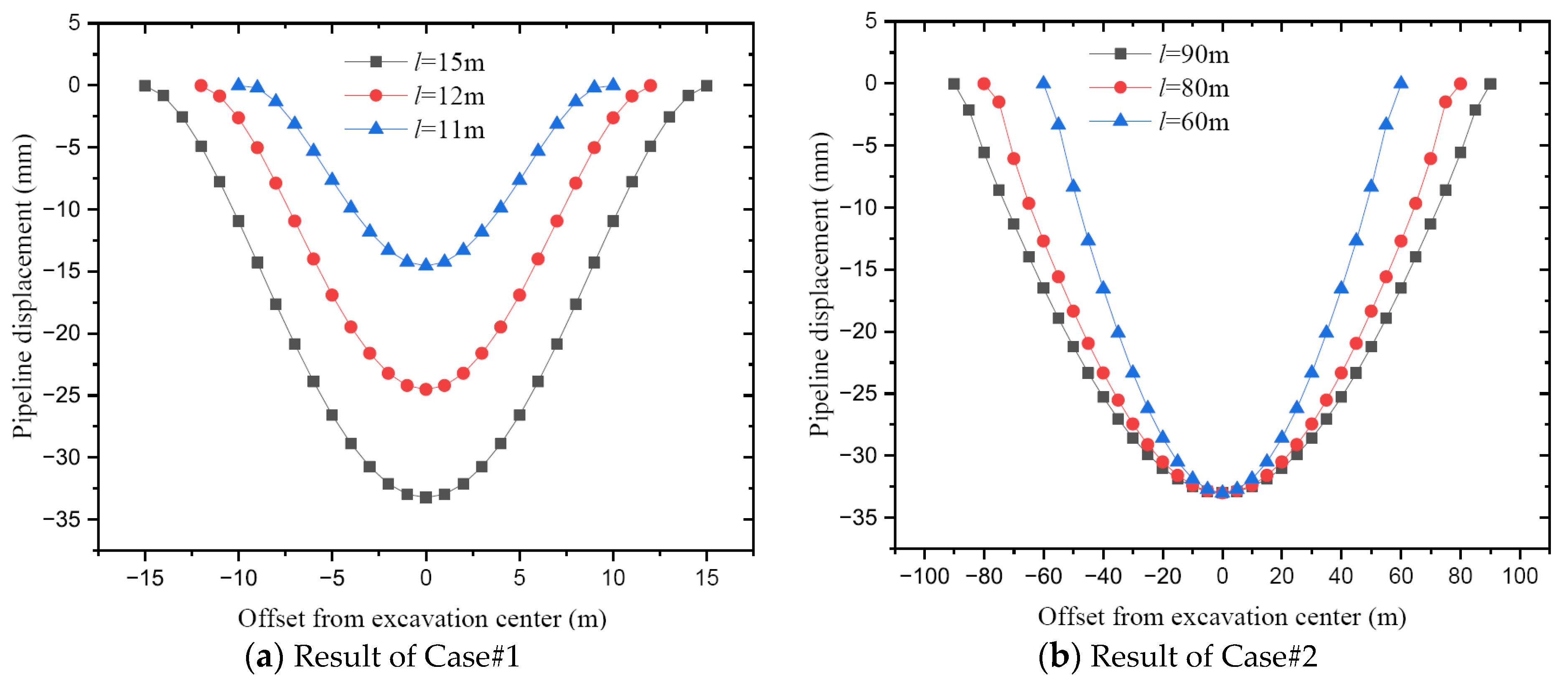
3.2.2. The Effects of Calculated Length l on the Pipeline Settlement

The ranges and values of parameters involved in Case#1 and Case#2 are l = 11~15 m and l = 60~90 m, respectively. It is clearly seen from Figure 7 that the calculated length l has a significant impact on the settlement displacement of pipelines. In Case#1, the maximum settlement increases with the calculated length l. When l increases from 11 m to 15 m, the maximum settlement displacement of pipelines increases by 128.04% (from 14.55 mm to 33.18 mm). In Case#2, although there is substantially no change for the peak settlement of pipelines with length l increase, there is a certain change in displacement on both sides. This is related to the calculated length l of Case#2.
Figure 8 illustrates the effects of the calculated length l on the maximum settlement. The ranges and values of parameters involved in Case#1 and Case#2 are l = 5~50 m. It is clearly seen from Figure 8 that the maximum settlement displacement of pipelines first increases as the calculated length l is increased and then decreases slightly, and finally keeps a constant value as the calculated length l is further increased. It means that when the l increases to a certain level, the maximum settlement displacement is no longer changing. As compared with Figure 7, it can be concluded that even if the maximum settlement displacement is steady with the l increase, the settlement of other positions still changes conspicuously. Therefore, the calculated length l is also of great significance for predicting the settlement distribution of pipelines, and it is an important factor that cannot be ignored in the analytical calculation.

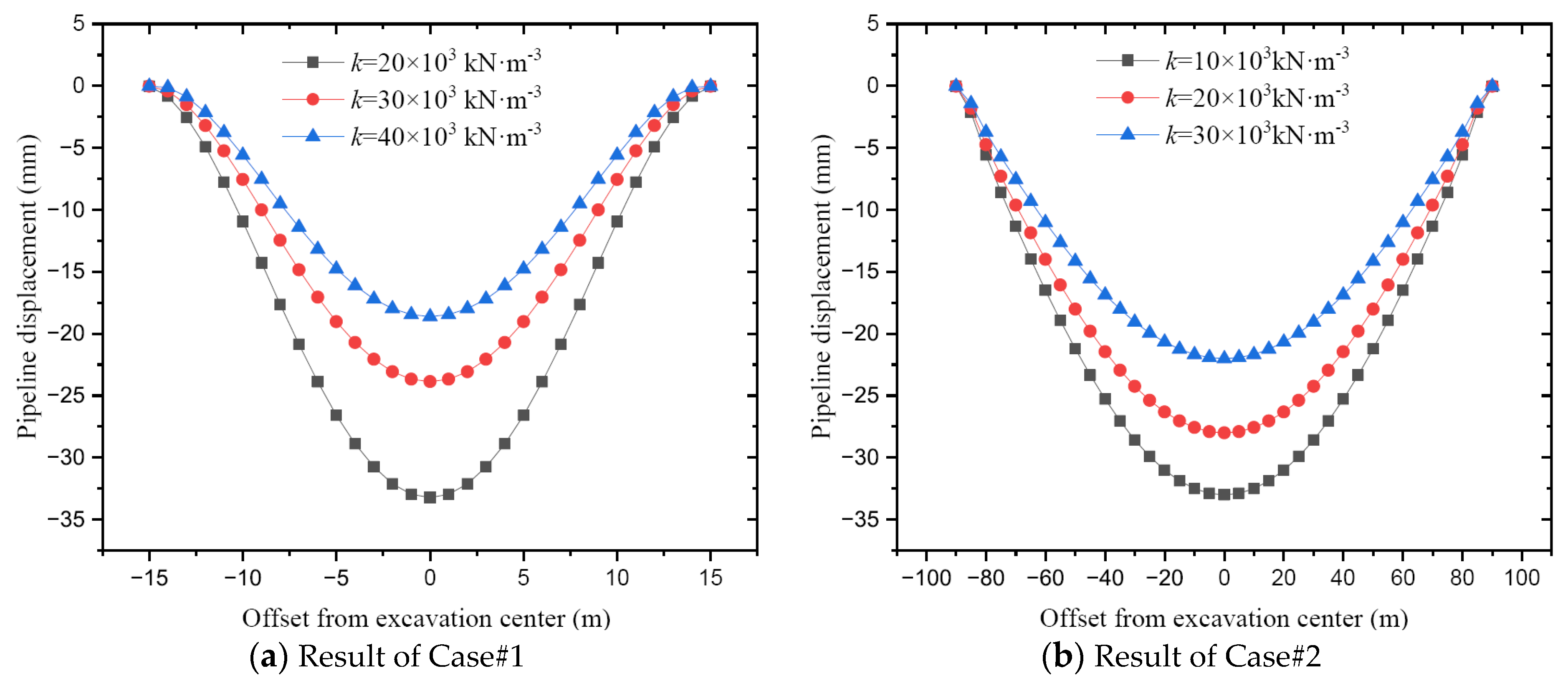
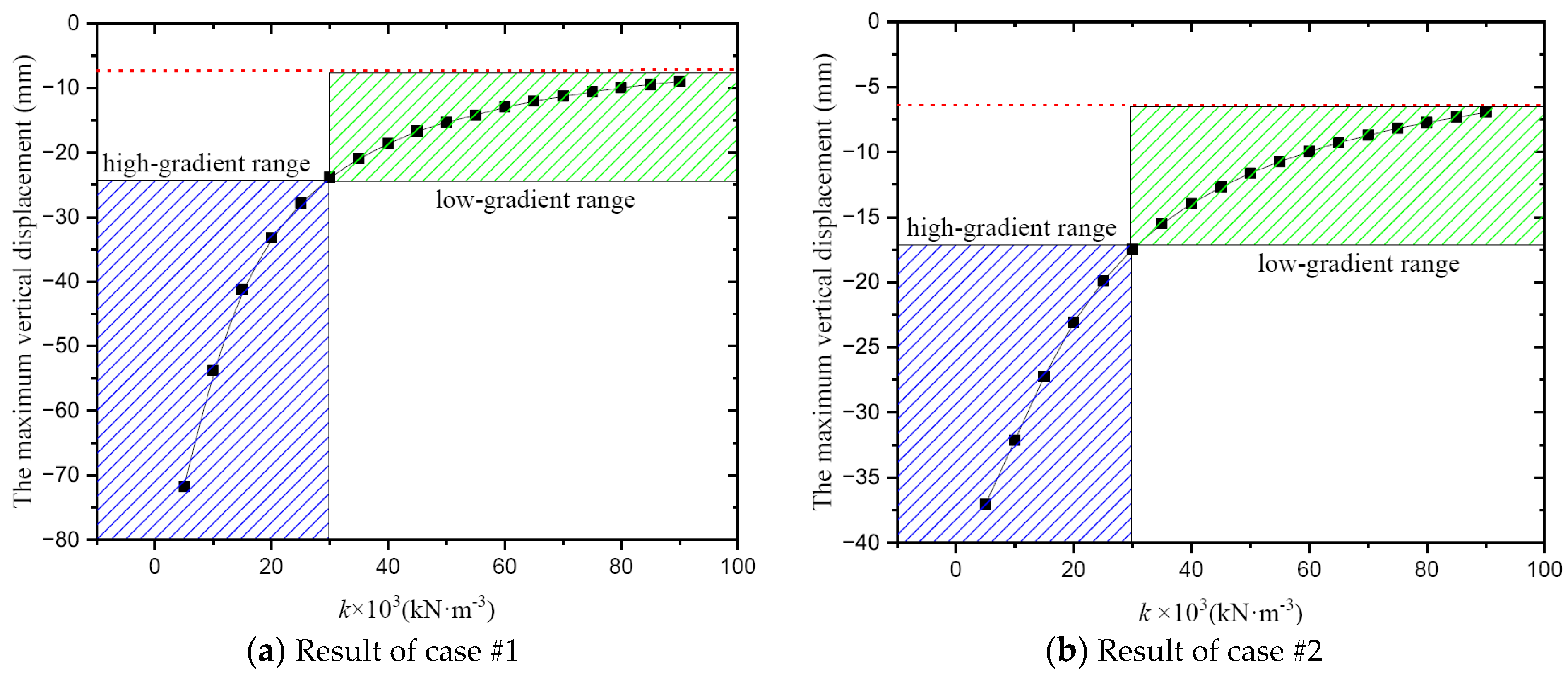
3.2.3. The Effects of Subgrade Modulus k on the Pipeline Settlement

The settlement displacement of pipelines is calculated under different values of the subgrade modulus illustrated in Figure 9. As is to be expected, the settlement displacement decreases with an increase in the subgrade modulus k, and the maximum settlement is also highly sensitive to the change in k. As for an illustration in Case#1, when k increases from 20 × 10 kN/m3 to 40 × 10 kN/m3, the settlement decreases by 44.48% (from 33.25 mm to 18.46 mm). In Case#2, when k increases from 10 × 10 kN/m3 to 30 × 10 kN/m3, the settlement decreases by 33.28% (from 32.96 mm to 21.99 mm). That is because, the higher the subgrade modulus k, the more difficult deformation is. Thus, determining the reasonable subgrade modulus parameter is a critical step during the analytical calculation. Obviously, this depends on the abundant engineering geological investigation data.
The relationship between the maximum settlement and subgrade modulus is shown in Figure 10. It can be seen from Figure 10 that the maximum settlement displacement value of pipelines first decreases as the subgrade modulus k is increasing, and then the value of settlement tends towards stability. When the subgrade modulus k is small, the settlement displacement gradient has a relatively high value because the soil deformation may be great. This large change gradient is reflected mainly in the small modulus stage, especially before the subgrade modulus k = 30 × 10 kN/m3. This indicates that the deformation of pipelines in the small subgrade modulus should be the focus of attention.
Figure 11 and Figure 12 show the influence of pipeline diameter and elastic modulus on the settlement displacement, respectively. In the calculated results, the settlement displacement, whether in curve shape or value, shows no significant change. From this, it can be seen that the influence of these two parameters on settlement can be ignored.
Obviously, these analysis results indicate that the significance orders of calculated parameters for the settlement displacement of a buried pipeline are as follows: subgrade modulus k, ground displacement δ, calculated length l, diameter d, and elastic modulus E.

4. An Engineering Application

4.1. General Description

A deep foundation pit is located in Beijing and the average excavation depth is 21 m. Due to the geological condition being very complicated, the pile-anchor joint supporting system was decided on. The length of the support pile in the foundation pit is 25 m, which means the buried depth is 4 m. The foundation pit is 450 m in circumference, and is 10,660 m2 in area. Investigation data show that a power pipeline is buried 2 m below the ground surface on the east side of the foundation pit. The positional relationship can be seen in Figure 13. The pipeline consists of concrete with a strength grade of C30. The pipeline structure is circular arch-vertical wall, and the clear section size is 2.0 × 2.3 m including a clear width of 2 m, clear height of 2.3 m, and rise of arches of 0.45 m. A composite lining is adopted, including an initial lining thickness of 0.25 m, and a secondary lining thickness of 0.25 m. The section of the pipeline is shown in Figure 14.
The main physical parameters of the soil layer in the area where the foundation pit is located are shown in Table 1.
A total of nine measuring points are arranged along the length direction of the pipeline, and the monitoring length is approximately 150 m. In Figure 13, the measuring point numbers are GX01~GX09, with a spacing of 20 m between GX02~GX08, 12 m between GX01~GX02, and 15 m between GX08~GX09. Additionally, CX4 and CX5 are two inclinometer holes on the east side of the pit wall, respectively. The distance between the measuring points and foundation pit side is shown in Table 2.

4.2. Analysis of the Pipeline Settlement Displacement

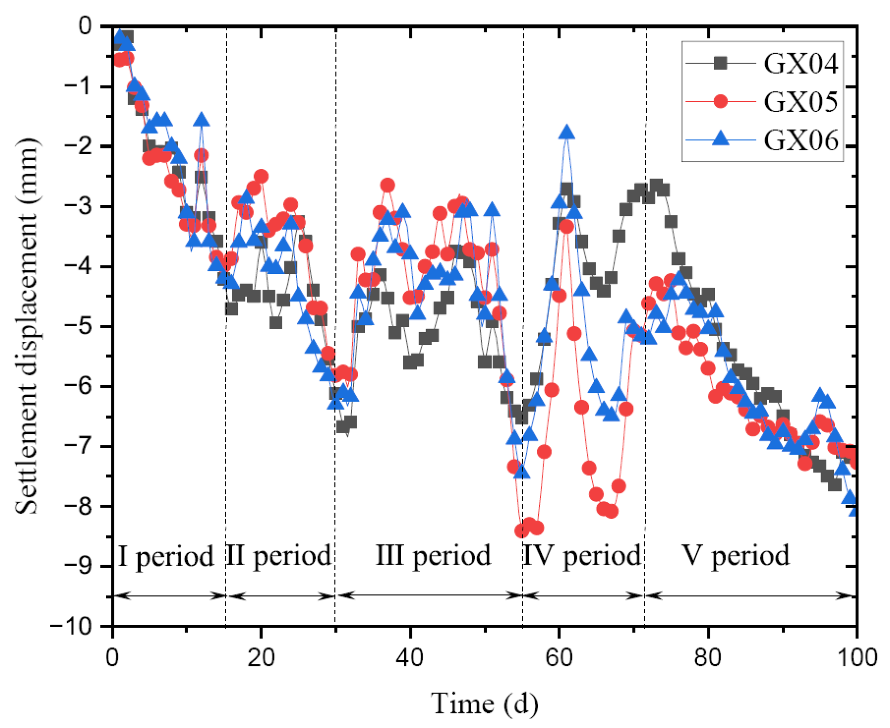
4.2.1. Analysis of the Measured Displacement

The settlement curves of different construction periods are selected for data analysis, and the results of GX04 to GX06 are shown in Figure 15. In this example, the construction period is divided into five stages and lasts for 93 days. The construction activities mainly contain Ⅰ period, construction of piling (0~14th day); Ⅱ period, construction of top beam and excavation (15~30th day); Ⅲ period, construction of anchor bar and excavation (31~56th day); Ⅳ period, construction of anchor bar and excavation (57~72nd day); Ⅴ period, construction of anchor bar and excavation (73~93rd day).
From Figure 15, it can be seen that in the Ⅰ period, the settlement of the pipeline is basically linearly related to the construction time. However, due to the influence of excavation depth and anchor bar support in different periods, there have been significant fluctuations in pipeline settlement. All excavation of the foundation pit is completed at 93 days, and, thereafter, the increase in pipeline settlement displacement obviously decreases and stabilizes. In the Ⅴ period, the displacement increase rates of GX04 to GX06 are 0.18 mm/d, 0.11 mm/d, and 0.14 mm/d, respectively, which are less than the warning value of 3 mm/d.

4.2.2. Determination of Calculated Parameters

(1) Length of outmost boundary of the subsidence area
Based on the results of Table 1, the weighting method is used to calculate the average angle of the internal friction of soil, i.e., φ = 17°. The retaining wall height is 25 m, according to Equation (1), and the length of outmost boundary of the subsidence area affected by the foundation pit excavation can be calculated as
z 0 = H g tan 45 φ 2 = 25 × tan 45 17 2 = 18.49   m
(2) Bending stiffness
The power pipeline tunnel consists of concrete with a strength grade of C30, so its elastic modulus E = 3.0 × 10⁴ MPa. In order to simplify the calculation, the tunnel section is transformed into a hollow rectangle plane. The relevant geometric parameters are represented as B = 3.03 m, H = 3.3 m, b = 2 m, and h = 2.3 m. B and H are the length and width of the rectangle, respectively, and b and h are the length and width of the hollow part. Therefore, the bending stiffness of the power pipeline tunnel can be calculated as
E I = 3 × 10 10 × B H 3 b h 3 12 = 3 × 10 10 × 3.03 × 3.3 3 2 × 2.3 3 12 = 2.19 × 10 11 N m 2
(3) Calculated length
It can be seen from Figure 2 and Table 2 that most of the measuring points are in the range of the subsidence area; thus, the length of the power pipeline can be taken as the distance of GX01~GX09. It is deduced by calculation that the total length of the pipeline is 147 m, and then the round l = 150 m for the sake of convenience in the calculation.
(4) Subgrade modulus
The characteristics of the soil physical parameters are statistically analyzed according to the engineering geologic investigation data and the subgrade modulus k = 1.0 × 10⁷ N/m3 is adopted.
(5) Pipeline outer diameter
It is worth noting that the power pipeline tunnel sectionis hollow rectangular, and not circle. In order to determine the outer diameter D, a circle-section with equivalent stiffness is used to replace the rectangular-section under the same wall thickness conditions. According to Figure 14, the wall thickness of the pipeline is 0.515 m, so the relationship between the outer diameter D and inner diameter d can be expressed as
D = d + 0.515
Then, according to the general principle of material mechanics, we can derive the moments of inertia by
I = π D 4 d 4 64 = B H 3 b h 3 12
Thus, the outer diameter is D = 4.42 m, and the inner diameter is d = 3.91 m.
(6) Ground displacement
In analytical calculation, an important problem is how to determine the ground settlement corresponding to the center of the pipeline δ. Although this calculation work is hard, δ will be obtained by step-by-step calculation in this study. The basic consideration of the calculation method is to, at first, calculate the settlement of the retaining wall based on the inclinometer hole data, and then the settlement of the power pipeline, obtained with the interpolation calculation, using the distance between the pipeline and retaining wall. This study takes the measuring point GX05 as an example, and defines the position of GX05 as the coordinate origin and GX05→GX09 as the coordinate positive direction. From Figure 13, it can be seen that there are no inclinometer holes in the middle of the power pipeline, so δ can be calculated by data fitting. Additionally, it can also be observed that the inclinometer hole CX4 is adjacent to the measuring point GX03, and the settlement of GX03 can be calculated. On the basis of the introduction above, GX05 is the coordinate origin and the distance between GX03 and GX05 is 40 m. The inclinometer hole data of CX4 in the Ⅲ period of construction are as shown in Figure 16.
Based on the research results of Peck et al., it can be assumed that the ground settlement area is equal to the lateral area of the enclosure structure in this study [7]. Although this assumption may have some errors with actual conditions, under the conditions of standard construction during excavation, the error is relatively small. Using the inclinometer hole data of CX4, the lateral area of the enclosure structure is Sw = 19.22 × 104 mm2. The maximum settlement of CX4 can be calculated as
δ max = 2 S w z 0 = 2 × 19.22 × 10 4 18,490    = 20.79 mm
The ground settlement curve within the subsidence area is defined as triangular distribution, and the distance between the measuring point GX03 and edge of foundation pit is 11,209 mm. Thus, the settlement of GX03 can be expressed as
δ GX 03 = 20.79 × 18,490 11,209 18,490    = 8.19 mm
According to Equation (3), the ground settlement corresponding to the center of pipeline δ can be calculated as
δ = 8.19 cos π 2 × 150 × 40 = 8.96 mm
Similarly, the settlements in the Ⅱ and Ⅳ periods of construction are 6.88 mm and 5.02 mm, respectively.

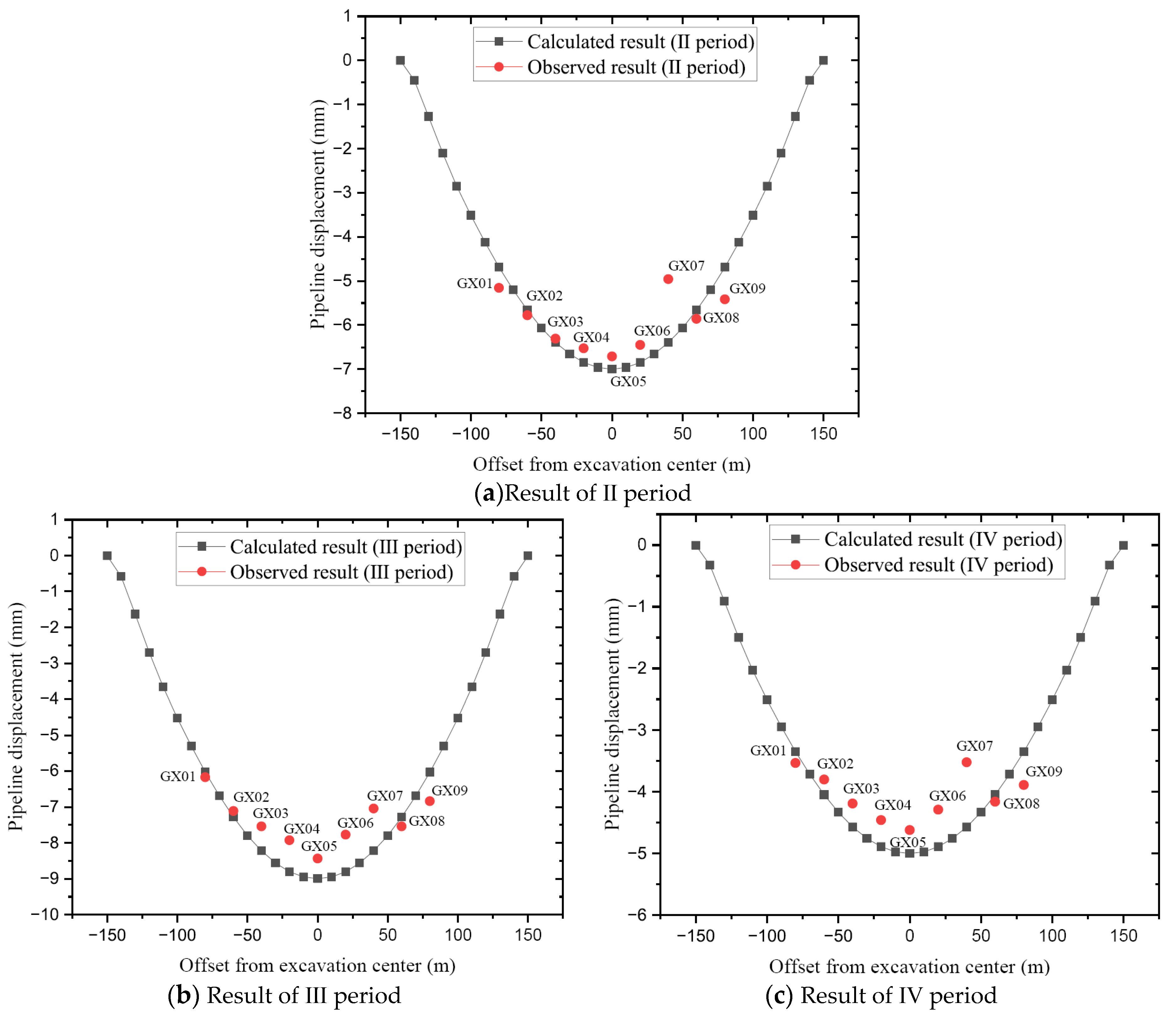
4.2.3. Result Analysis

The settlement curve compared with the observed data is shown in Figure 17. It is shown that although the calculated settlement displacement of the pipeline is deeper than the observed results and the maximum displacement is larger, the predictions from this study method are, in general, consistent with the observed data. By analyzing and comparing, it can also be seen that the proposed calculation method tends to be somewhat conservative. Actually, the comparison results of GX01~GX05 are better than those of GX06~GX09. The main reason is that the GX01~GX05 results are basically parallel to the edge of the foundation pit, and this distribution of measuring points agrees with the calculated model much better. For the measuring point GX05, due to the fact that the power pipeline is not parallel to the edge of the foundation pit, there is a large error between the calculated result and the measured data, but the trend of settlement and displacement changes at the GX06~GX09 is basically similar to the calculated results.
Figure 18 is the error bar chart of the measuring points, and the negative value indicates that the calculated result is less than the observed value. There is a maximum error in the vicinity of the GX07, and the value is about 30%. This error can hardly be lowered because of the complexity of the foundation pit edge in relation to pipeline location, and this working condition is still discussed in detail later in parameter analysis. The negative error appears primarily on both ends of the pipeline, and this is due to the boundary constraint conditions. Data analyses show that the other measuring point’s error is no more than 15%, and can even be less than 5%. The error results also prove the usefulness of the proposed method for a practical noncircular pipeline settlement analysis.
Figure 19 illustrates the settlement displacement of GX07~GX09 during different construction periods. As can be seen from the result, the settlement of GX07 is lower than the other measuring points, which is not consistent with the theoretical calculations. The calculation model focuses on the pipeline parallel to the edge of the foundation pit, and this use of assumption can attempt to explain the difference in results. It is precisely because the pipeline is not parallel to the edge of the foundation pit that the number of support piles around GX07 is greater than that around GX08, which effectively regulates the pipeline settlement during the construction period. For GX09, although its distance to the edge of the foundation pit is approximately equal to the distance from GX07, the settlement value is larger than the value of GX07. It can be attributed to the fact that GX09 is adjacent to GX08, and the continuity of pipeline deformation leads to a relatively high settlement value.

5. Discussion

In the traditional analysis method, it is assumed that the pipeline is parallel to the edge of the foundation pit. However, it is hard to accurately obtain this ideal working condition in the actual engineering because the foundation pit distribution is a bit complicated and also has many influencing factors. Thus, the determination of the calculated length l is a rigorous challenge for the calculation accuracy of pipeline settlement.
In the above engineering example, the pipeline is not completely parallel to the edge of the foundation pit, and the length of the outmost boundary of the subsidence area is z0 = 18.49 m. From Table 2, it can be seen that the maximum distance from the selected measuring points GX02~GX09 to the edge of the foundation pit is 14.55 m, which is within the calculation range. Despite GX01 being out of the calculation range, it is located at the end of the power pipeline and has little effect on the results. In fact, the characteristics of this engineering example are that there is pipeline distributed within the length range of the outmost boundary of the subsidence area; thus, the calculated length can be taken as the actual length of the pipeline. Finally, the determination foundation of the calculated parameter is validated by good agreement between the calculated results and observed data.
Although the pipeline may not necessarily be parallel to the edge of the foundation pit, the determination of the calculated length is based on the actual length of the affected pipeline within the length range of the outmost boundary of the subsidence area, which agrees with the actual working conditions much better. Up until now, there has still been little research on how to divide the working condition relationship between pipelines and the foundation pit; thus, the above understanding also needs to be proven in practice. The problem regarding the determination of the calculated length will also be discussed exhaustively in a future study.

6. Conclusions

A simplified analysis model for the deformation of buried pipelines based on the theory of elastic foundation beams caused by excavation is proposed in this study, and the influences of various parameters on the settlement, namely, ground displacement, calculated length, subgrade modulus, diameter, and elastic modulus, are also investigated here. The feasibility of this simplified analytical method is verified by comparing it with the results of earlier cases, and the practicality of this method is also verified by an engineering example. The main conclusions are su mmarized as follows:
(1) The settlement displacement of the buried pipeline obtained using this present method is slightly larger than the observed data of earlier cases and the engineering example, but the shapes of the settlement curves of calculated and recorded results are consistent, which is beneficial for a reasonable evaluation of buried pipeline deformation.
(2) The effects of different parameters on the maximum settlement displacement are discussed, and the order of correlation is as follows: subgrade modulus k > ground displacement δ > calculated length l > diameter d > elastic modulus E. The parameters k, δ, and l are more sensitive to the settlement displacement, and the effects of d and E can be ignored. The settlement displacement only increases linearly with an increase in the ground displacement δ; when subgrade modulus k and calculated length l increase to a certain value, the settlement displacement will remain stable.
(3) In order to overcome the drawback of the pipeline not being parallel to the edge of the foundation pit, this study proposes using the actual length of the pipeline within the length range of the outmost boundary of the subsidence area as the calculated length l, which shows satisfactory results.
(4) According to the principle of bending stiffness equivalence, the simplified analysis model is used not only for the pipeline of a circular cross section, but also for the pipeline of a non-circular cross section.

Author Contributions

Conceptualization, investigation, methodology, Y.L. and X.C.; data processing, J.H.; original draft, Y.L.; writing and editing the draft, Y.L. and Y.J. All authors have read and agreed to the published version of the manuscript.

Funding

This research was funded by the Hebei Natural Science Foundation (No. E2021512002); Langfang Science and Technology Research and Development Plan Project (No. 2021011065); and the Key Laboratoryof Building Collapse Mechanism and Disaster Prevention, China Earthquake Administration (No. FZ211104).

Institutional Review Board Statement

Not applicable.

Informed Consent Statement

Not applicable.

Data Availability Statement

The data used to support the finding of this study are available from the corresponding authors upon request.

Acknowledgments

The authors express appreciation to Haiyan Li for editing and English language assistance.

Conflicts of Interest

The authors declare no conflict of interest.

References

  1. Li, X.Q.; Zhang, Z.H.; Sun, C. Situation and prospects of excavation impact on adjacent underground pipelines. J. Jilin Jianzhu Univ. 2015, 32, 13–18. [Google Scholar]
  2. Liu, M.; Ortega, R. Assessment of impact to buried pipelines due to tunneling-induced settlement. J. Pipeline Syst. Eng. Pract. 2023, 14, 04023020. [Google Scholar] [CrossRef]
  3. Yu, C.; Han, C.J.; Xie, R.; Wang, L. Mechanical behavior analysis of buried pipeline under stratum settlement caused by underground mining. Int. J. Press. Vessel. Pip. 2020, 188, 104212. [Google Scholar] [CrossRef]
  4. Jiao, N.; Ding, J.W.; Ji, F.; Guo, K.; Liao, Z.S. Analysis on influence of deep foundation pit excavation in soil-rock composite stratum on deformation of adjacent pipelines. J. Southeast Univ. 2022, 52, 229–236. [Google Scholar]
  5. Kouretzis, G.P.; Karamitros, D.K.; Sloan, S.W. Analysis of buried pipelines subjected to ground surface settlement and heave. Can. Geotech. J. 2015, 52, 1058–1071. [Google Scholar] [CrossRef]
  6. Zhang, Z.G.; Zhang, M.X.; Zhao, Q.H. A simplified analysis for deformation behavior of buried pipelines considering disturbance effects of underground excavation in soft clays. Arab. J. Geosci. 2015, 8, 7771–7785. [Google Scholar] [CrossRef]
  7. Peck, R.B. Deep excavation and tunneling in soft ground, Deep excavations and tunneling in soft ground. In Proceedings of the 7th International Conference on Soil Mechanics and Foundation Engineering, State of the Art Volume, Mexico City, Mexico, 3–5 August 1969; pp. 225–290. [Google Scholar]
  8. Gong, X.N.; Sun, Z.J.; Yu, J.L. Analysis of displacement of adjacent buried pipeline caused by ground surcharge. Rock Soil Mech. 2015, 36, 305–310. [Google Scholar]
  9. Jiang, Z. Theoretical analysis on deformation of pipeline caused by adjacent foundation pit excavation. Chin. J. Undergr. Space Eng. 2014, 10, 362–368. [Google Scholar]
  10. He, X.L.; Yang, T.H.; Zhou, Y.W.; Liang, L.J.; Xu, C.J. Analysis of pipeline displacement induced by adjoining foundation pit excavation considering pipeline-soil separation. J. Civ. Environ. Eng. 2019, 41, 9–16. [Google Scholar]
  11. Zhao, S.W.; Li, X.L.; Li, X.; Chen, L.G.; Li, T.; Li, S.H.; Bai, Y. Analysis of pipeline deformation caused by shield tunnel excavation that obliquely crosses existing pipelines. Arab. J. Geosci. 2022, 15, 227. [Google Scholar] [CrossRef]
  12. Zhu, J.; Zhu, D.Y. Deformation of pipelines induced by the construction of underlying twin-tunnel. Tehnicki Vjesnik-Technical Gazette 2020, 27, 1311–1315. [Google Scholar]
  13. Lin, C.G.; Huang, M.S.; Nadim, F.; Liu, Z.Q.; Yu, J. Analytical solutions for tunnelling-induced response of two overlying pipelines. Tunneling Undergr. Space Technol. Inc. Trenchless Technol. Res. 2021, 108, 103678. [Google Scholar] [CrossRef]
  14. Crofts, J.E.; Menziest, B.K.; Tarzi, A.I. Lateral displacement of shallow buried pipelines due to adjacent deep trench excavations. Geotechnique 1977, 27, 161–179. [Google Scholar] [CrossRef]
  15. Dong, Y.P.; Burd, H.J.; Houlsby, G.T. Finite-Element Investigation of excavation-induced settlements of buildings and buried pipelines. J. Geotech. Geoenviron. Eng. 2022, 148, 04022072. [Google Scholar] [CrossRef]
  16. Zhang, J.; Liang, Z.; Zhao, G.H. Mechanical behaviour analysis of a buried steel pipeline underground overload. Eng. Fail. Anal. 2016, 63, 131–145. [Google Scholar] [CrossRef]
  17. Zhang, K.Y.; Torres, J.L.C.; Zang, Z.J. Numerical analysis of pipelines settlement inducedby tunneling. Adv. Civ. Eng. 2019, 2019, 4761904. [Google Scholar]
  18. Song, Z.P.; Wu, Y.C.; Zhang, Y.W.; Wang, K.S.; Tian, J.L.; Tian, X.X. Deformation response of a pipeline to nearby deep foundation pit excavation: Numerical simulations and field tests. Appl. Sci. 2023, 13, 6579. [Google Scholar] [CrossRef]
  19. Alshboul, O.; Almasabha, G.; Shehadeh, A.; Al Hattamleh, O.; Almuflih, A.S. Optimization of the structural performance of buried reinforced concrete pipelines in cohesionless soils. Materials 2022, 15, 4051. [Google Scholar] [CrossRef]
  20. Almasabha, G.; Shehadeh, A.; Alshboul, O.; Al Hattamleh, O. Structural performance of buried reinforced concrete pipelines under deep embankment soil. Constr. Innov. 2023. ahead-of-print. [Google Scholar] [CrossRef]
  21. Uribe-Henao, A.F.; Arboleda-Monsalve, L.G.; Mackie, K. Building response to excavation-induced ground movements from a nonlinear-inelastic perspective. J. Struct. Eng. 2023, 149, 04023021. [Google Scholar] [CrossRef]
  22. Liao, P.Y.; Ni, P.P.; Ma, B.S.; Sun, W.; Wang, A.X. Centrifuge and numerical modeling of brittle damage of buried pipelines subjected to tunneling induced ground settlements. Tunneling Undergr. Space Technol. Inc. Trenchless Technol. Res. 2023, 138, 105158. [Google Scholar] [CrossRef]
  23. Liu, H.Y.; Li, H.E.; Huang, Y.S. Displacement calculation on nearby underground pipeline caused by deep excavation based on field test of ground displacement. Ind. Constr. 2011, 41, 72–75. [Google Scholar]
  24. Liu, X.B.; Chen, Y.L.; Meng, W.B. Two-stage method on the displacement of underground pipelines caused by excavation of deep foundation pit. J. Univ. Shanghai Sci. Technol. 2019, 41, 479–484. [Google Scholar]
  25. Tan, Y.; Lu, Y. Responses of shallowly buried pipelines to adjacent deep excavations in Shanghai soft ground. J. Pipeline Syst. Eng. Pract. 2018, 9, 05018002. [Google Scholar] [CrossRef]
  26. Zhang, J.Q.; Zhang, K.L.; Cheng, G.F. Characteristics of surface settlement and deformation of open cut foundation pit in different areas of Beijing. Hydrogeol. Eng. Geol. 2021, 48, 131–139. [Google Scholar]
  27. Guo, P.P.; Gong, X.N.; Wang, Y.X.; Lin, H.; Zhao, Y.L. Analysis of observed performance of a deep excavation straddled by shallowly buried pressurized pipelines and underneath traversed by planned tunnels. Tunn. Undergr. Space Technol. 2023, 132, 104946. [Google Scholar] [CrossRef]
  28. Yang, Y.B.; Chen, C.Y.; Liu, C.; Huang, L.T.; Chen, W.; Lin, N.Y.; Cui, J.; Xie, W.D. Performance of a deep excavation and the influence on adjacent piles: A case history in karst region covered by clay and sand. Undergr. Space 2023, 8, 45–60. [Google Scholar] [CrossRef]
  29. Li, D.Y.; Zhang, T.Q.; Gong, X.N. Analysis of the displacements of buried pipelines caused by deep excavations. Ind. Constr. 1999, 29, 36–42. [Google Scholar]
  30. Liu, G.B.; Wang, W.D. Excavation Engineering Handbook, 2nd ed; Architecture & Building Press: Beijing, China, 2009. [Google Scholar]
  31. Wu, W. Analytical analysis of the impact on adjacent underground pipelines due to foundation pit excavation on the Pasternak foundation. J. Water Resour. Water Eng. 2019, 30, 212–216. [Google Scholar]
Figure 1. Buried pipeline failure case [25].
Applsci 13 10356 g001
Figure 2. Mechanic model of buried pipeline.
Applsci 13 10356 g002
Figure 3. Comparison of calculated result and Case#1.
Applsci 13 10356 g003
Figure 4. Comparison of calculated result and Case#2.
Applsci 13 10356 g004
Figure 5. Effect of ground displacement on the pipeline settlement.
Applsci 13 10356 g005
Figure 6. Relationship between ground displacement and maximum settlement displacement.
Applsci 13 10356 g006
Figure 7. Effect of calculated length on the pipeline settlement.
Applsci 13 10356 g007
Figure 8. Relationship between calculated length and maximum settlement displacement.
Applsci 13 10356 g008
Figure 9. Effect of subgrade modulus on the pipeline settlement.
Applsci 13 10356 g009
Figure 10. Relationship between subgrade modulus and maximum settlement displacement.
Applsci 13 10356 g010
Figure 11. Effect of diameter on the pipeline settlement.
Applsci 13 10356 g011
Figure 12. Effect of elastic modulus on the pipeline settlement.
Applsci 13 10356 g012
Figure 13. Plan view of the foundation pit excavation and buried power pipeline.
Applsci 13 10356 g013
Figure 14. Power pipeline tunnel section.
Applsci 13 10356 g014
Figure 15. Relationship of pipeline settlement with construction time (GX04~GX06).
Applsci 13 10356 g015
Figure 16. Inclinometer curve of CX4.
Applsci 13 10356 g016
Figure 17. Comparison of calculated result and observed result in different construction periods.
Applsci 13 10356 g017
Figure 18. Error of measured value and calculated value.
Applsci 13 10356 g018
Figure 19. Relationship of pipeline settlement with construction time (GX07~GX09).
Applsci 13 10356 g019
Table 1. Physical parameters of soil.
Soil LayerThickness/mCohesion/kPaFrictional Angle/(°)Density/(kN·m−3)
Miscellaneous fill0.50816.5
Silty clay0.5~5.616.82219.3
Sandy clay0.9~7.318.52019.2
Silty clay4.7~10.630.61220.6
Fine sandy0.8~6.561517.4
Silty clay3.5~21.517.62019.1
Weathered Granite19.2~27.5332221.5
Table 2. Length between measuring points and foundation pit side.
NumberDistance/mmNumberDistance/mm
GX0123,617GX0214,549
GX0311,209GX0410,744
GX0511,497GX0617,048
GX0713,250GX087778
GX0913,174
Disclaimer/Publisher’s Note: The statements, opinions and data contained in all publications are solely those of the individual author(s) and contributor(s) and not of MDPI and/or the editor(s). MDPI and/or the editor(s) disclaim responsibility for any injury to people or property resulting from any ideas, methods, instructions or products referred to in the content.

