Abstract
In this paper, a simulation model for Selective Laser Melting (SLM) technology is established to simulate the additive manufacturing process of a turbine impeller for an aerospace engine. By utilizing the simulation model, variations in laser power and scanning speed are employed to obtain simulated results of thermal deformation for the turbine impeller under different laser power and scanning speed conditions. The results indicate that the thermal deformation of the component increases with the augmentation of laser power, decreases with the escalation of scanning speed, and eventually stabilizes. Based on the relationship between thermal deformation and energy, the energy utilization efficiency of the SLM process under different conditions is calculated. The findings demonstrate that, within a certain range of power, the synergistic effect of laser power and scanning speed allows for an increase in energy utilization efficiency and a reduction in processing time while ensuring the mechanical performance of the formed parts. Consequently, this approach proves effective in lowering production costs for complex components based on SLM technology.
1. Introduction
Selective Laser Melting (SLM), a form of metal additive manufacturing [1,2,3,4,5,6], offers advantages such as design flexibility, minimized material waste, and rapid production of intricate components [7,8]. It holds significant potential in industries demanding precision and strength, including the aerospace [9,10,11,12,13] and medical [14] sectors. The SLM process involves intricate stages like heating, cooling, and phase transition, contributing to challenges such as porosity, cracks, and warping in the final products [15]. In the SLM process, laser power and scanning speed are important parameters that affect the molding qualities. As the laser power increases, the amount of heat the part absorbs per unit of time also changes. This leads to variable heat accumulation effects, which alter the part’s thermal deformation. Similar to how the scanning speed affects the part’s thermal deformation, the machining duration affects the thermal accumulation effect. A large thermal deformation of the component will result in a loss of the part’s mechanical qualities, which will impair normal use of the part or shorten its useful life. Employing finite element simulation on complex, realistic structures during SLM manufacturing can effectively enhance production quality and thereby play a pivotal role in reducing associated costs.
An examination of the production process using numerical simulations can successfully prevent flaws in the forming process, increase production efficiency during actual printing, and provide feedback for the production process. Zhao et al. [16] conducted a numerical simulation analysis of the temperature field of a formed 5356 aluminum alloy using the life-death element method through ABAQUS 2020. The study revealed that reciprocating additive forming can effectively improve the surface irregularities caused by heat accumulation at the arc termination in the unidirectional additive process. Additionally, appropriate preheating of the substrate led to a more uniform temperature distribution. Yao et al. [17] employed the life-death element and moving heat source (DFLUX) methods in ABAQUS for thermo-mechanical coupling analysis of three typical thin-walled structures. They computed the temperature field for a single cladding path, used these results as initial conditions for stress analysis, and determined that the most significant deformation occurred during the initial deposition and cooling periods. Yang et al. [18] used a tetrahedral mesh to refine the laser additive remanufacturing area, established a finite element model of a water turbine blade, and investigated the transient distribution of temperature and stress fields during the additive manufacturing process. Results indicated that the effects of stress, strain, and temperature were primarily concentrated in the additive remanufacturing region. Baiges et al. [19] employed an octree-based adaptive meshing method to compute stress fields, refining the mesh for regions requiring computation. The study found that accuracy was affected by simplification strategies, which could be compensated by introducing correction terms to mitigate accuracy loss caused by coarsening. Talagani et al. [20] employed a rule-based rectangular mesh division for the Strati car model, controlling the finite element model size by specifying spatial increments of the background grid to analyze stress fields. Simulation results showed that using GENOA for micro-mechanical damage pattern calculation resulted in additional inter-bead crack formation, and additional loads could be applied to the printed structure after generating the finite element grid for the vehicle. Bian P et al. [21] developed an efficient and rapid simulation method based on the thermal-mechanical coupling algorithm using a moving heat source model and elastic-plastic welding simulation theory. They developed the simulation of SLM process to address coupling simulation problems. Through performance testing simulation on thin and hollow parts, the study demonstrated that thermal stress increased with layer height and decreased after substrate removal, and the maximum uniaxial plane stress transitioned from tensile to compressive stress from the edge to the center, ultimately reaching an equilibrium state. During the printing of thin plates, macroscopic thermal deformation was concentrated at the same plane corner, with the greatest deformation occurring in the z-axis direction.
Laser power and scanning speed are important process parameters that affect the molding quality and mechanical properties of parts. Jiang et al. [22] found that with the increase in scanning speed, the number of pore defects and porosity increased in the SLM-formed Ti-6Al-4V alloy. The alloy structure exhibited acicular α’ martensite, and the scanning speed had little influence on the microstructure morphology, but the effect of scanning power was not considered. Song et al. [23] conducted numerical simulations on the formation process of aircraft hinge structures at different scanning speeds using three laser powers and found that residual stress and deformation showed a trend of improvement followed by deterioration with increasing laser power. Kruth et al. [24] utilized SLM technology to print a bridge-shaped structure and evaluated residual stress qualitatively using the bridge curvature method. They compared the effects of different laser scanning patterns, parameter settings, and process parameters on residual stress and found that the part exhibited overall upward warping after separating from the substrate. Yan et al. [25] discovered that using zone island scanning during the printing of TC4 material effectively reduced the maximum warping. He et al. [26] created a simulation model of the temperature field for a single-layer multi-pass method at various scanning speeds while accounting for the microstructure morphology. They combined experiments to analyze the generation of defects, microstructure, and mechanical properties, including anisotropy. The results showed that with the increase of laser scanning speed, the wettability of the liquid phase decreased, the internal porosity increased, and with the increase of scanning speed, the depth and width of the melt pool gradually decreased, making it difficult to form a good metallurgical bond. Guo et al. [27] found that when SLM printing, a volumetric energy density that is too low will cause cracks and form irregular shape defects, and when it is too large, a large amount of powder will be attached to the surface, and even serious warpage deformation will occur, accompanied by large-sized round holes.
The conventional method for inspecting the quality of SLM forming is experimental, involving mechanical analysis of simple printed specimens to assess whether the designed process parameters yield satisfactory model quality. In this study, by simulating the manufacturing process of a turbine structure for aerospace engine turbines, the optimal solution for process parameters is analyzed without the need for physical printing. This approach addresses the issue of poor interpretability between simple structural samples and complex components, which is often encountered in experimental methods.
Through analysis of process parameters, this study investigates the energy utilization efficiency during the manufacturing process of turbine pump structures using SLM. This research has the potential to effectively reduce production costs for complex components based on the SLM method.
2. Research Methodology
2.1. Governing Equation
In addressing the heat transfer-flow-solidification process within the molten pool [28,29,30,31], a “heat-flow” coupled model has been established for simulation and computation. This model assumes the molten metal liquid to be an incompressible Newtonian fluid while neglecting the impact of turbulence. The specific governing equations are as follows:
Continuity equation:
Conservation of momentum equation:
Conservation of energy equation:
In the equation, subscripts i and j denote Cartesian coordinate directions; ρ represents density; vi stands for the velocity component in the i direction; t is time; p signifies pressure; μ is the dynamic viscosity of the molten metal; kP is the mushy zone coefficient; bj represents the body force, including buoyancy, gravity, and other fluid-driving forces; h denotes the latent heat of fusion; k stands for the thermal conductivity coefficient; cP represents the specific heat capacity; ΔH represents the latent heat absorbed during material melting; and s signifies the volumetric heat source.
The boundary conditions for the flow field primarily consider the influence of surface tension on molten pool flow while disregarding the effects of recoil pressure and the Marangoni effect on molten pool flow. The thermal boundary conditions encompass heat sources, thermal convection, and heat conduction, among which thermal convection is the primary cause of energy loss.
2.2. Heat Source Modeling
In the simulation and computation of SLM additive manufacturing, a common approach is to employ a heat source model to simulate the material’s absorption of energy instead of directly modeling the laser. One frequently used model for the laser heat source is the Moving Heat Source (MHS) model [32]. This method is based on the heat conduction equation for numerical computation. The MHS approach can capture the non-uniform and variable nature of the actual laser scanning path while considering factors such as laser irradiation time, power, scanning speed, and their effects.
In the equation provided, represents the density of the metal; c denotes the specific heat capacity of the metal; k stands for the thermal conductivity of the metal; Q signifies the laser power density absorbed by the metal per unit time; T represents the temperature of the metal; t is the time; and S corresponds to the laser power density.
In the context of the MHS (Moving Heat Source) method, the parameter in the formula represents the time constant of the laser heat source. It holds crucial significance as a control parameter governing the time response of the laser heat source. Specifically, the value of is often determined by the laser’s pulse width and Full Width at Half Maximum (FWHM). A smaller indicates a faster response of the laser heat source, leading to greater variations in the heat source power density. Conversely, a larger results in a slower response of the heat source, causing smoother changes in the heat source power density.
2.3. Energy Utilization Equation
Based on the relationship between thermal deformation and temperature change, as well as the relationship between energy and temperature change, the equation for thermal deformation in terms of energy can be expressed as follows:
where ΔL represents the displacement deformation of the part caused by thermal effects; ΔT signifies the change in material temperature during the manufacturing process; α denotes the coefficient of thermal expansion of the material (which depends solely on the material’s inherent properties); c is the material’s specific heat coefficient; m represents the mass of the part; Q1 denotes the heat absorbed by the part during the manufacturing process; and Q2 is the total energy released by the laser during the processing.
The temperature distribution inside a metal can be described by the heat conduction equation [33]:
where ρ is the density of the metal, c is the specific heat capacity of the metal, k is the thermal conductivity, Q is the power density of laser absorbed by the metal per unit time, T is the temperature, and t is the time.
The heat conduction equation inside the metal describes the manner and rate at which thermal energy is transferred within the metal, taking into account the thermal conductivity properties of the metal and temperature differences. This equation plays a fundamental role in the simulation and computational modeling of metal additive manufacturing processes.
Through the displacement deformation of the part during processing, the temperature change of the part from powder to processing can be calculated, so as to obtain the absorbed power of the part. By calculating the total power, the energy utilization rate of the part processing process can finally be obtained.
3. Simulation
3.1. A Geometric Model of the Turbine Pump Impeller
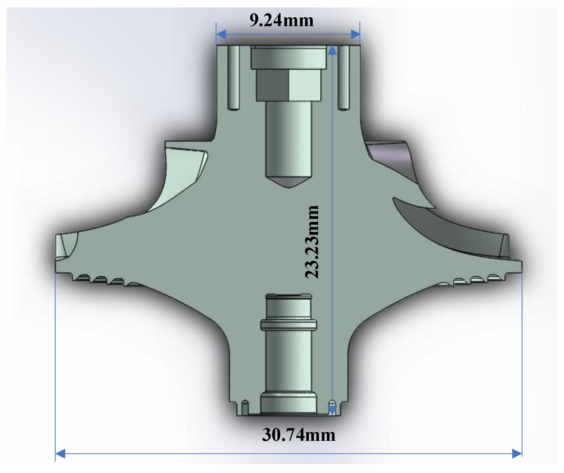
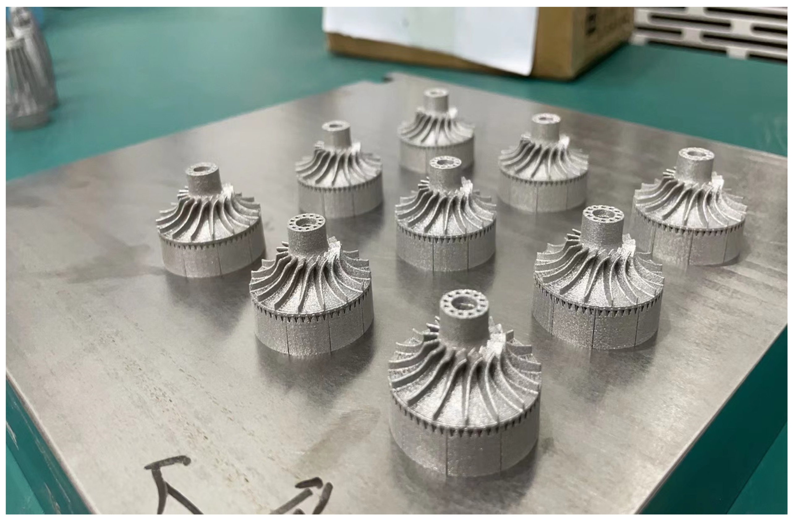
Integrating the design of the turbine pump impeller offers the advantage of reducing welding processes and component assembly. This approach helps to prevent significant internal stresses and residual deformations caused by welding. Furthermore, integrated design effectively mitigates stress concentration at the intersections of welds and welding components, thereby enhancing the structural strength and durability. The manufacturing of the turbine pump impeller using SLM is illustrated in Figure 1 and Figure 2, while the model parameters for both modeling and actual manufacturing are outlined in Table 1.
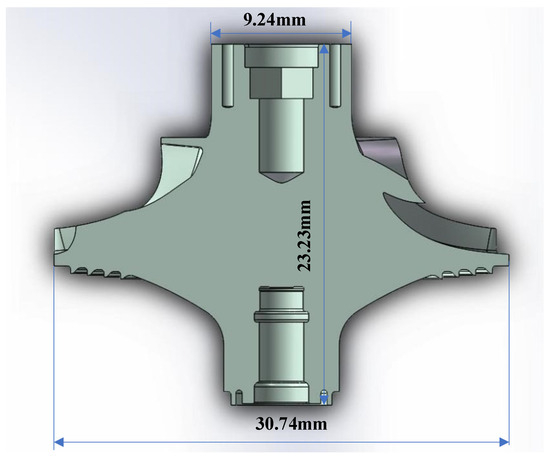
Figure 1.
Geometric model of the turbine pump impeller.
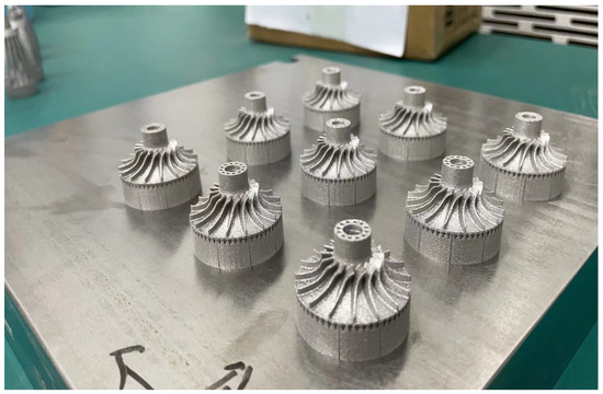
Figure 2.
Physical prototype of the turbine pump impeller manufactured using SLM.

Table 1.
Geometric model parameters.
3.2. Material and Process Parameter Settings
Considering the real-world application context of the turbine pump, titanium alloy was selected as the material for the simulation experiments. The physical characteristic parameters of TC4 are provided in the Table 2 shown below:
Table 2.
Material properties of TC4.
Simulation calculations are performed based on the actual SLM manufacturing process for the design of simulation process parameters. The fundamental process parameters are presented in Table 3. By varying the laser power and scanning speed, the physical characteristics of the turbine pump impeller structure are analyzed under different parameter settings. This analysis aims to achieve optimal formability quality and energy utilization efficiency.
Table 3.
Manufacturing parameters in the simulation [34].
3.3. Simulation Results
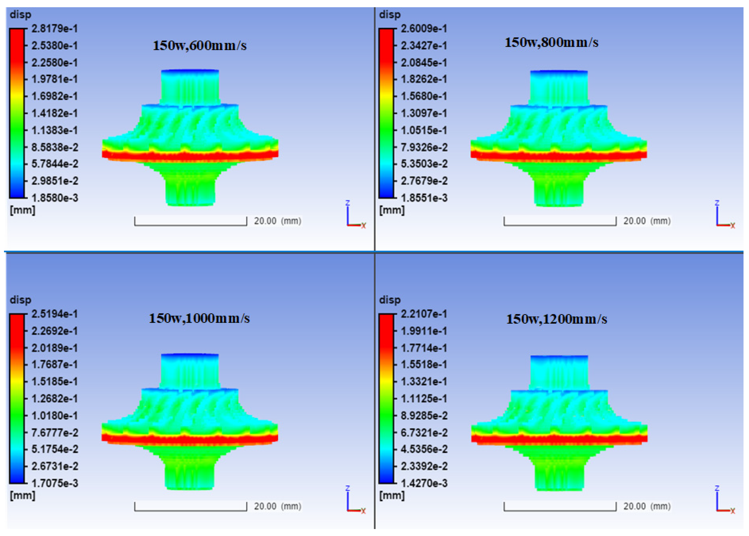
The simulation results depicting displacement deformation of the turbine pump impeller model under different laser power and scanning speed parameters are illustrated in Figure 3.

Figure 3.
Simulation results of displacement deformation at different scanning speeds for laser power of 150 W.
At a power of 150 W, the maximum displacement deformation is concentrated at the edge of the turbine pump impeller’s base, as shown in Figure 3. This phenomenon is mainly attributed to the larger cross-sectional area of the base, which requires the longest time for each layer to be processed. Consequently, during the base processing, the powder needs to absorb a higher amount of laser energy. Simultaneously, since the base edge is the first to be scanned in that layer, strong heat accumulation occurs due to the time effect. Under the influence of this heat accumulation effect, significant thermal deformation is observed in the base.
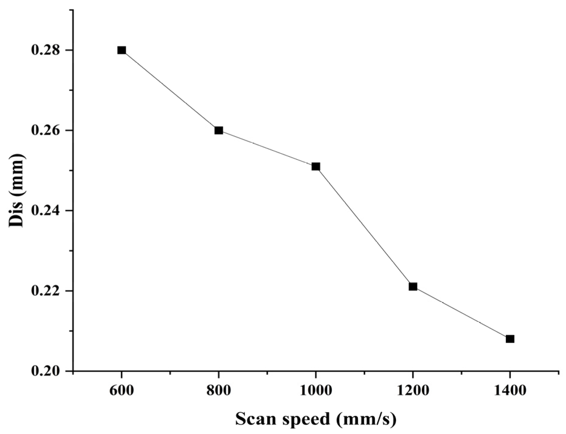
As the scanning speed increases, the displacement deformation of the part gradually diminishes, and the deformation size exhibits an approximate linear relationship with scanning speed, as shown in Figure 4. This is primarily because, with constant power, an increase in scanning speed leads to reduced interaction time between the laser and the material. As a result, the material cannot absorb sufficient laser energy, causing the thermal effect in the melt pool to gradually decrease. Consequently, the thermal deformation of the part induced by this thermal effect also reduces accordingly.
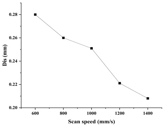
Figure 4.
Effect of scanning speed on deformation.
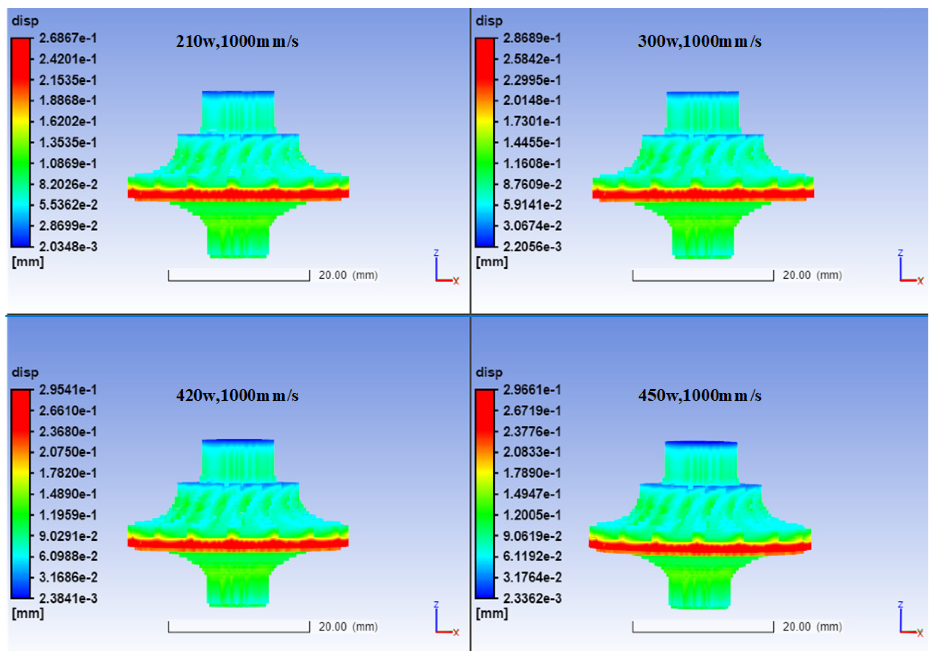
However, when the scanning speed is 1000 mm/s, with an increase in laser power, as depicted in Figure 5 and Figure 6, the thermal deformation of the part gradually increases, but the rate of deformation growth diminishes. Under constant scanning speed, raising the laser power enables the material to absorb more laser energy per unit time. Consequently, the thermal effect in the melt pool strengthens progressively, leading to a gradual increase in thermal deformation of the part caused by the thermal effect in the melt pool.
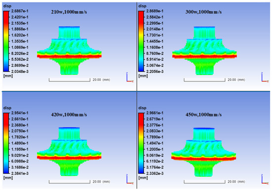
Figure 5.
The simulated results of displacement deformation for different powers at a scanning speed of 1000 mm/s.
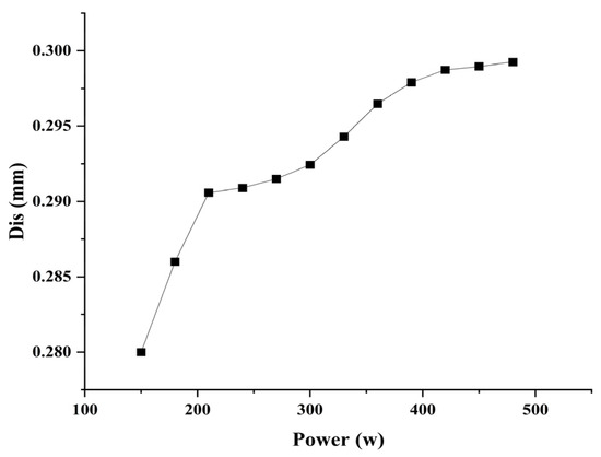
Figure 6.
The influence of laser power on deformation.
As both laser power and scanning speed can influence thermal deformation, we obtain the relationship diagram between laser power, scanning speed, and thermal deformation, as shown in Figure 7. Due to the combined effect of laser power and scanning speed, the part’s deformation exhibits nonlinear variation. This nonlinearity arises because, while an increase in power allows the material to absorb more laser energy per unit time, simultaneously increasing the laser scanning speed reduces the interaction time between the material and the laser. It is precisely this interaction between laser power and scanning speed that necessitates the selection of appropriate laser power and scanning speed during part printing to mitigate thermal deformation, ensure mechanical performance, reduce manufacturing time, and enhance energy utilization efficiency. Therefore, it is essential to conduct simulation calculations before printing.
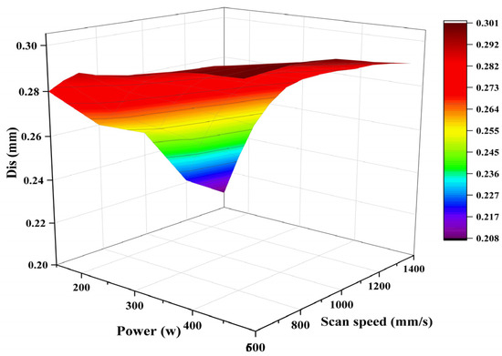
Figure 7.
The combined effects of laser power and scanning speed on deformation.
4. Energy Utilization
Throughout the entire manufacturing process, while maintaining a constant laser power and considering the scanning time of the laser, it is possible to calculate the total energy released through the laser. In the SLM method, the energy consumption during part fabrication is primarily attributed to the melting and solidification of powder. By utilizing the temperature field variations in the simulated impeller structure, this study calculates the energy consumption required for the fabrication of the impeller. Consequently, by comparing the actual energy absorbed by the turbine pump impeller with the total energy released by the laser, the energy utilization efficiency of the turbine pump impeller’s SLM manufacturing process can be determined.
When the laser power remains constant and the scanning speed increases, the energy utilization efficiency also changes accordingly, as shown in Figure 8. While the relationship between laser scanning speed and energy utilization efficiency still exhibits an approximate linear trend, unlike thermal deformation, the energy utilization efficiency gradually increases with an increase in laser scanning speed. Consequently, within a certain range of power, energy utilization efficiency can be enhanced by raising the scanning speed. This enhancement in energy utilization efficiency also facilitates a reduction in manufacturing time. However, it is worth noting that an increase in scanning speed results in reduced interaction time between the laser and the material, which may lead to partial melting of the material and a portion remaining in an unmelted state. This can eventually lead to an increase in porosity, affecting the mechanical properties of the final part.
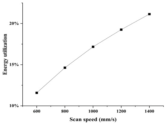
Figure 8.
Energy utilization efficiency at different scanning speeds.
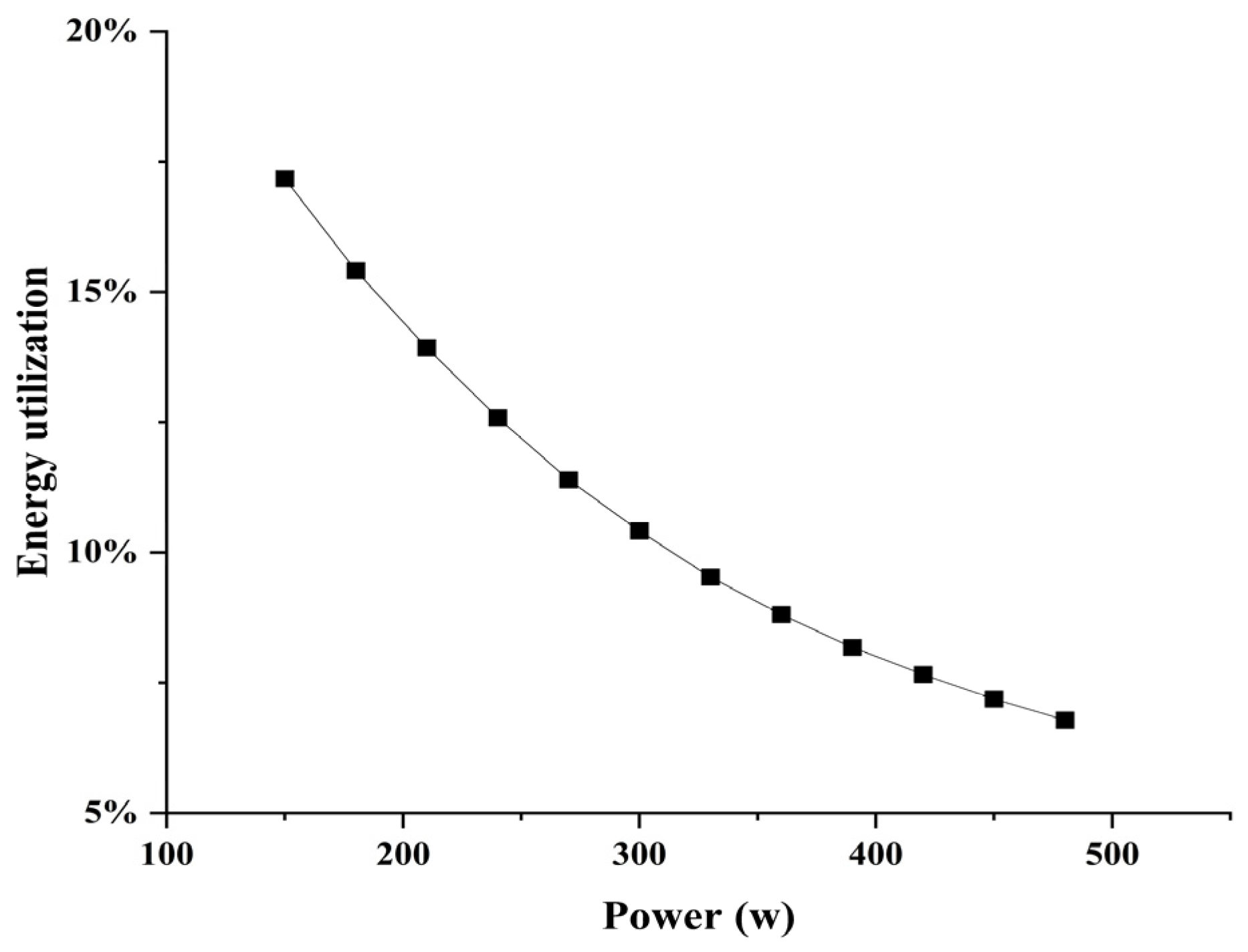
With an unchanged scanning speed, increasing the laser power leads to a decrease in energy utilization efficiency. As shown in Figure 9, when the laser power reaches a certain level, the energy utilization efficiency stabilizes. Therefore, within a specific range, to ensure that the material can absorb enough energy for melting and guarantee the mechanical performance of the formed part, it is possible to appropriately increase the laser power without causing a significant decrease in energy utilization efficiency.

Figure 9.
Energy utilization efficiency at different powers.
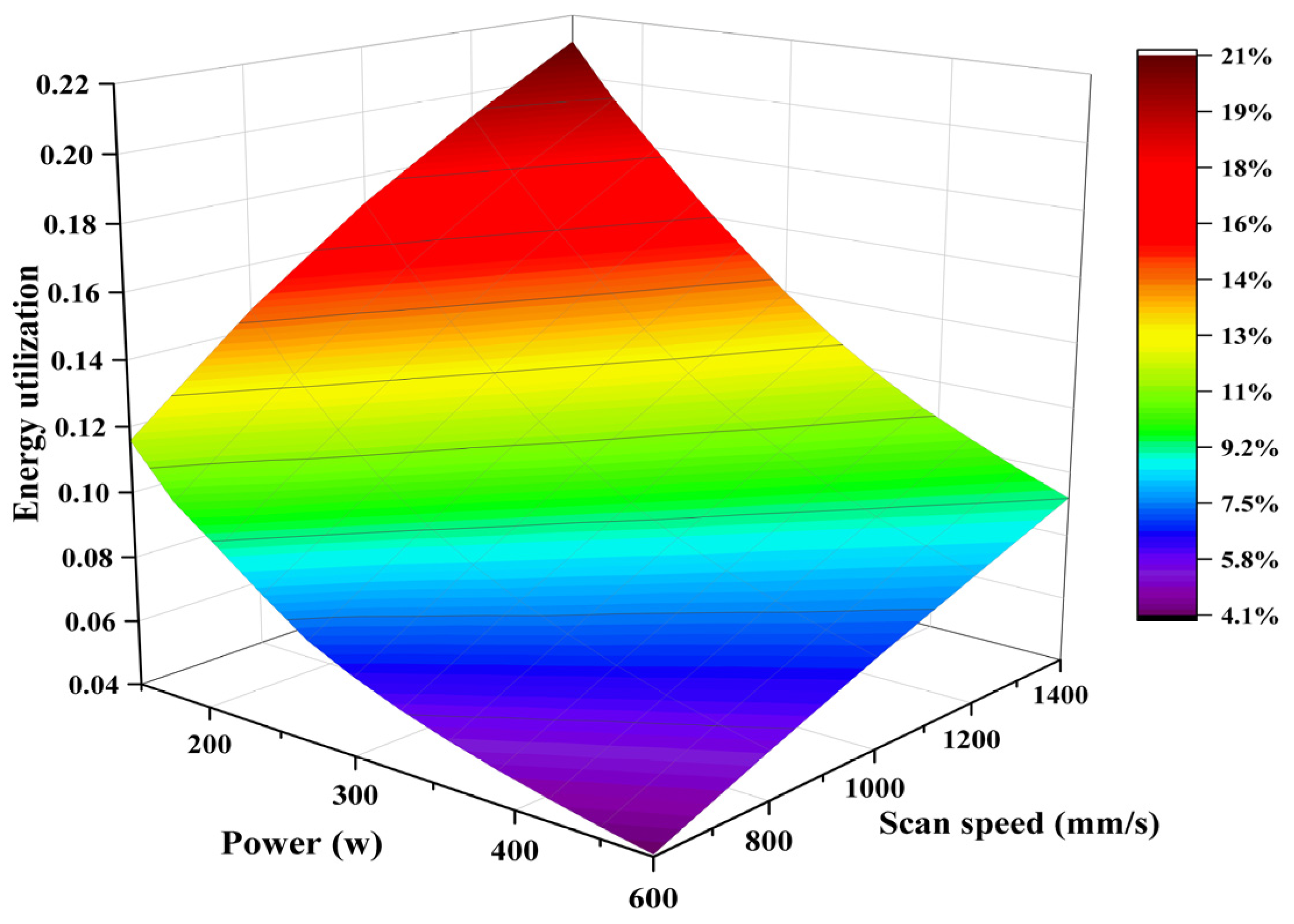
Due to the combined effect of laser power and scanning speed, different power and scanning speed combinations can achieve similar energy utilization efficiencies, as shown in Figure 10. Under the combined influence of laser power and scanning speed, the energy utilization efficiency changes within a certain range. In the actual processing process, the material absorbs a portion of the laser energy for melting, and heat conduction occurs between adjacent materials, enabling the material to utilize this part of the laser energy. Simultaneously, another portion of the laser energy is lost due to thermal convection and thermal radiation. Therefore, while ensuring that laser energy is maximally absorbed and utilized, the selection of appropriate laser power and scanning speed contributes to enhancing the SLM processing efficiency and the quality of part formation.

Figure 10.
Energy utilization.
5. Conclusions
This study aims to enhance the forming quality of complex structural components prepared using the SLM method, improve the energy utilization efficiency of SLM-based turbine pump processing, and reduce part manufacturing costs. Through simulation-based calculations, this paper analyzes the thermal deformation generated during the fabrication process of turbine pump impellers. It investigates the energy utilization efficiency of turbine pump impellers manufactured using the SLM method. The mapping relationships between parameters such as laser power and scanning speed and the generation of thermal deformation and energy utilization efficiency are derived. The following conclusions have been drawn:
- (1)
- With a constant laser power, increasing the laser scanning speed leads to a reduction in the thermal deformation of the part, exhibiting an approximately linear relationship.
- (2)
- When the scanning speed remains unchanged and the laser power is increased, the thermal deformation of the part also increases and eventually stabilizes.
- (3)
- Within a certain range of laser power, increasing the scanning speed can enhance energy utilization efficiency and shorten the printing time simultaneously.
- (4)
- Keeping the scanning speed constant while increasing the laser power might lead to a decrease in energy utilization efficiency. This can result in stronger thermal accumulation and an increase in thermal deformation of the formed part.
- (5)
- The maximum thermal deformation of the turbine pump impeller occurs at the edge of the base. Thus, in the actual manufacturing process, increasing the thickness of the base appropriately can ensure sufficient mechanical performance.
The limitations of this study include the following aspects. Firstly, the influence of recoil pressure and the Marangoni effect on the flow of the molten pool has not been considered. Secondly, the study primarily focuses on thermal conduction and thermal convection, while neglecting the impact of thermal radiation on energy utilization efficiency. In future research, we will address these shortcomings and conduct focused investigations to enhance the accuracy of simulation results. This effort aims to provide solid theoretical support for the preparation of complex components using the SLM method.
Author Contributions
Conceptualization, J.G. and Y.W. (Yongqiu Wang); methodology, J.G.; software (Additive 2021), J.G.; validation, J.G., S.P. and F.W.; formal analysis, Y.W. (Yingzan Wang); investigation, J.G.; resources, J.G.; data curation, Y.W. (Yingzan Wang); writing—original draft preparation, Y.W. (Yongqiu Wang); writing—review and editing, J.G.; visualization, J.G.; supervision, J.G.; project administration, J.G.; funding acquisition, J.G. All authors have read and agreed to the published version of the manuscript.
Funding
This research was funded by National Natural Science Foundation of China (grant number 52205110 and 52305544), the Project of Guangdong Science and Technology Innovation Strategy (grant number STKJ2021177 and STKJ202209065), and the STU Scientific Research Foundation for Talents (grant number NTF20019 and NTF20014).
Institutional Review Board Statement
Not applicable.
Informed Consent Statement
Not applicable.
Data Availability Statement
Not applicable.
Conflicts of Interest
The authors declare no conflict of interest.
References
- Sun, C.; Wang, Y.; McMurtrey, M.D.; Jerred, N.D.; Liou, F.; Li, J. Additive Manufacturing for Energy: A Review. Appl. Energy 2021, 282, 116041. [Google Scholar] [CrossRef]
- Herzog, D.; Seyda, V.; Wycisk, E.; Emmelmann, C. Additive Manufacturing of Metals. Acta Mater. 2016, 117, 371–392. [Google Scholar] [CrossRef]
- Liu, G.; Zhang, X.; Chen, X.; He, Y.; Cheng, L.; Huo, M.; Yin, J.; Hao, F.; Chen, S.; Wang, P.; et al. Additive Manufacturing of Structural Materials. Mater. Sci. Eng. R Rep. 2021, 145, 100596. [Google Scholar] [CrossRef]
- Lim, S.; Buswell, R.A.; Le, T.T.; Austin, S.A.; Gibb, A.G.F.; Thorpe, T. Developments in Construction-Scale Additive Manufacturing Processes. Autom. Constr. 2012, 21, 262–268. [Google Scholar] [CrossRef]
- Veiga, F.; Suarez, A.; Aldalur, E.; Artaza, T. Wire Arc Additive Manufacturing of Invar Parts: Bead Geometry and Melt Pool Monitoring. Measurement 2022, 189, 110452. [Google Scholar] [CrossRef]
- Casuso, M.; Veiga, F.; Suárez, A.; Bhujangrao, T.; Aldalur, E.; Artaza, T.; Amondarain, J.; Lamikiz, A. Model for the Prediction of Deformations in the Manufacture of Thin-Walled Parts by Wire Arc Additive Manufacturing Technology. Metals 2021, 11, 678. [Google Scholar] [CrossRef]
- Guo, X.; Chen, Z. Merical simulation of laser additive manufacturing process: A review. Acta Aeronaut. Astronaut. Sin. 2021, 42, 234–246. [Google Scholar]
- Wang, H. Materials’ fundamental issues of laser additive manufacturing for high-performance large metallic components. Acta Aeronaut. Astronaut. Sin. 2014, 35, 2690–2698. [Google Scholar]
- An, G. Application and prospect of metal additive manufacturing technology in aerospace. Moden Mach. 2019, 3, 39–43. [Google Scholar]
- Li, D.; Lu, Z.; Tian, X.; Zhang, H.; Yang, C.; Cao, Y.; Miao, K. Additive manufacturing—Revolutionary technology for leading aerospace manufacturing. Acta Aeronaut. Astronaut. Sin. 2022, 43, 22–38+3. [Google Scholar]
- Ren, H.; Zhou, G.; Cong, B.; Ma, H.; Dong, W. Development and application of metal additive manufacturing in aerospace field. Aeronaut. Manuf. Technol. 2020, 63, 72–77. [Google Scholar]
- Tepylo, N.; Huang, X.; Patnaik, P.C. Laser-Based Additive Manufacturing Technologies for Aerospace Applications. Adv. Eng. Mater. 2019, 21, 1900617. [Google Scholar] [CrossRef]
- Zhu, Z.; Zhao, K.; Guo, L.; Yang, Y.; Zhao, W.; Hao, Y.; Yang, P. Application and development trend of additive manufacturing technology of large-scale metal component in aerospace manufacturing. Electr. Weld. Mach. 2020, 50, 1–14+124. [Google Scholar]
- Griffin, K.; Pappas, D. 3D Printed Microfluidics for Bioanalysis: A Review of Recent Advancements and Applications. TrAC Trends Anal. Chem. 2023, 158, 116892. [Google Scholar] [CrossRef]
- Yao, X.; Wang, J.; Yang, Y.; Zhang, X.; Cheng, X.; Zhang, S. Review on defect mechanisms and control methods of metallic components during laser additive manufacturing. Chin. J. Lasers 2022, 49, 286–296. [Google Scholar]
- Zhao, P.; Tang, C.; Yang, M.; Jing, Z.; Li, Y. Numerical simulation analysis of temperature field of 5356 aluminum alloy based on TIG arc additive manufacturing. Ordnance Mater. Sci. Eng. 2021, 44, 71–77. [Google Scholar]
- Yao, B.; Ma, L.; Chen, J.; Wang, Z. Numerical simulation analysis of thermal stress and distortion of typical structural parts wire and arc. Mech. Sci. Technol. Aerosp. Eng. 2022, 41, 961–970. [Google Scholar]
- Yang, D.; Li, D.; Chen, Z.; Zhao, J.; Chen, X. Simulation study of temperature field and stress field in laser additive remanufacturing of hydraulic turbine blade. Appl. Laser 2022, 42, 44–51. [Google Scholar]
- Baiges, J.; Chiumenti, M.; Moreira, C.A.; Cervera, M.; Codina, R. An Adaptive Finite Element Strategy for the Numerical Simulation of Additive Manufacturing Processes. Addit. Manuf. 2021, 37, 101650. [Google Scholar] [CrossRef]
- Talagani, M.R.; DorMohammadi, S.; Dutton, R.; Godines, C.; Baid, H. Numerical Simulation of Big Area Additive Manufacturing (3D Printing) of a Full Size Car. Sampe J. 2015, 51, 27–36. [Google Scholar]
- Bian, P.; Shao, X.; Du, J. Finite Element Analysis of Thermal Stress and Thermal Deformation in Typical Part during SLM. Appl. Sci. 2019, 9, 2231. [Google Scholar] [CrossRef]
- Jiang, X.; Xia, W.; Lou, D.; Ren, X.; Shao, S.; Li, H.; Liu, S.; Fang, X. Effect of Scanning Speed on Internal Defects and Mechanical Properties of Ti-6Al-4V Alloy Processed by Selective Laser Melting. Mater. Mech. Eng. 2020, 44, 41–45. [Google Scholar] [CrossRef]
- Song, Y.; Long, Y.; Guo, D.; Liu, Z.; Wang, W.; Zhou, W.; Liu, Z.; Yang, Y. Numerical simulation of the influence of process parameters on the SLM forming of hinge. J. Mach. Des. 2020, 37 (Suppl. 2), 54–57. [Google Scholar]
- Kruth, J.-P.; Deckers, J.; Yasa, E.; Wauthlé, R. Assessing and Comparing Influencing Factors of Residual Stresses in Selective Laser Melting Using a Novel Analysis Method. Proc. Inst. Mech. Eng. Part B J. Eng. Manuf. 2012, 226, 980–991. [Google Scholar] [CrossRef]
- Yan, H.; Shen, L.; Wang, X.; Tian, Z.; Xu, G.; Xie, D.; Liang, H. Stress and Deformation Evaluation of the Subarea Scanning Effect in Direct Laser-Deposited Ti-6Al-4V. Int. J. Adv. Manuf. Technol. 2018, 97, 915–926. [Google Scholar] [CrossRef]
- He, K.; Zhou, L.; Yang, L. Microstructure and Mechanical Properties of 316L Stainless Steel in the Selective Laser Melting. Laser Optoelectron. Prog. 2020, 57, 091404. [Google Scholar]
- Guo, Y.W.; Wei, W.; Shi, W.; Xue, D.; Zhou, X.R.; Wen, S.P.; Wu, X.L.; Gao, K.Y.; Huang, H.; Nie, Z.R. Selective Laser Melting of Er Modified AlSi7Mg Alloy: Effect of Processing Parameters on Forming Quality, Microstructure and Mechanical Properties. Mater. Sci. Eng. A 2022, 842, 143085. [Google Scholar] [CrossRef]
- Cadiou, S.; Courtois, M.; Carin, M.; Berckmans, W.; Le Masson, P. Heat Transfer, Fluid Flow and Electromagnetic Model of Droplets Generation and Melt Pool Behaviour for Wire Arc Additive Manufacturing. Int. J. Heat Mass Transf. 2020, 148, 119102. [Google Scholar] [CrossRef]
- Jiang, Z.; Xu, P.; Liang, Y.; Liang, Y. Deformation Effect of Melt Pool Boundaries on the Mechanical Property Anisotropy in the SLM AlSi10Mg. Mater. Today Commun. 2023, 36, 106879. [Google Scholar] [CrossRef]
- Xie, S.; Zhu, B.; Qiao, J.; Zhuang, Y.; Zhao, Y.; Zou, J. Molten Pool Air-Liquid Interface in High-Power Laser Manufacturing: Evolution Law and Energy Absorption Characteristics. Surf. Interfaces 2023, 41, 103214. [Google Scholar] [CrossRef]
- Chu, J.; Wang, X.; Ma, Y.; Liu, H. Numerical Simulation of Melt Pool Formation in Laser Transmission Joining PET with Microtextured Surface Pretreated SUS304 Stainless Steel. Int. J. Heat Mass Transf. 2023, 216, 124560. [Google Scholar] [CrossRef]
- Mirazimzadeh, S.E.; Pazireh, S.; Urbanic, J.; Hedrick, B. Investigation of Effects of Different Moving Heat Source Scanning Patterns on Thermo-Mechanical Behavior in Direct Energy Deposition Manufacturing. Int. J. Adv. Manuf. Technol. 2022, 120, 4737–4753. [Google Scholar] [CrossRef]
- Chiumenti, M.; Neiva, E.; Salsi, E.; Cervera, M.; Badia, S.; Moya, J.; Chen, Z.; Lee, C.; Davies, C. Numerical Modelling and Experimental Validation in Selective Laser Melting. Addit. Manuf. 2017, 18, 171–185. [Google Scholar] [CrossRef]
- Chakkravarthy, V.; Manojkumar, P.; Lakshmanan, M.; Eswar Prasad, K.; Dafale, R.; Vadhana, V.C.; Narayan, R.L. Comparing Bio-Tribocorrosion of Selective Laser Melted Titanium-25% Niobium and Conventionally Manufactured Ti-6Al-4 V in Inflammatory Conditions. J. Alloys Compd. 2023, 952, 169852. [Google Scholar] [CrossRef]


Disclaimer/Publisher’s Note: The statements, opinions and data contained in all publications are solely those of the individual author(s) and contributor(s) and not of MDPI and/or the editor(s). MDPI and/or the editor(s) disclaim responsibility for any injury to people or property resulting from any ideas, methods, instructions or products referred to in the content. |
© 2023 by the authors. Licensee MDPI, Basel, Switzerland. This article is an open access article distributed under the terms and conditions of the Creative Commons Attribution (CC BY) license (https://creativecommons.org/licenses/by/4.0/).