Abstract
This study proposes a new numerical method for the free vibration analysis of elastically restrained tapered Rayleigh beams with concentrated mass and axial force. The beam model had elastic support, concentrated mass at both ends, and axial force at the right end. The elastic supports were modeled as translational and rotational springs. The shear force and bending moment were determined under the assumption that the sum of the forces at arbitrary positions and the joint between the beam and elastic supports always becomes zero. Therefore, a frequency determinant is established considering the free-free end condition at both ends, but various boundary conditions were constructed by adjusting the values of the elastic springs in the frequency equation. This assumption simplified the deduction procedure, and the method’s efficiency was demonstrated through various comparisons. In particular, the value of compressive loading at which the first natural frequency vanished was investigated by considering the taper ratio based on the relationship between the elastic support and compressive loading. The analyzed results can be adopted as benchmark solutions for other approaches. The frequency determinant employs the transfer matrix method; however, numerical methods can easily be utilized in other approaches.
1. Introduction
Several researchers have extensively studied tapered beams to investigate the variations in the dynamic characteristics of beams experiencing various environments in many engineering applications, such as columns, girders, and rotor blades. The effects of elastic supports, concentrated mass, and axial loading have been included [1,2,3], and a combination of these effects has been discussed [4,5,6]. Such beam structures have received attention from many researchers [7,8,9] for analyzing the dynamic characteristics of many structures with intermediate or elastic supports at both ends where fully clamped boundary conditions cannot be employed.
To obtain more accurate results, shape functions due to the cross-section varying along the length of the tapered beam were studied [10,11,12], and the solution of the power series to solve differential equations was employed [13]. The differential equation for the special case of a tapered Bernoulli–Euler beam is solved with Bessel’s function [14,15]. Employing classical beam theory, a cantilever uniform beam [16] and a cantilever tapered beam [17] attached to a concentrated mass at the free end were studied to analyze their effects on the natural frequencies. The characteristic equations for the unknown constants were determined by substituting the solution of the differential equation into the boundary and continuity conditions.
The effects of constant axial and gravity loads on tapered beams have also been investigated [4,18]. The effect of constant axial tensile and compressive loads on the eigenpairs of a uniform beam was analyzed in detail by considering different boundary conditions [19,20], and when the compressive load reached the critical buckling loading, these effects were analyzed in detail for uniform beams with various end conditions. The buckling and post-buckling behaviors of a double-beam system supported on a Winkler-Pasternak elastic foundation under a compressive load were analyzed through numerous parametric studies [21]. To analyze the critical dynamic buckling loads, an axially compressed piezoelectric semiconductor rod simply supported at both ends was studied [22].
The transfer matrix method is the simplest and most powerful numerical tool for evaluating the dynamic characteristics of beam structures with elastic supports. It can be used simply by multiplying the change in state vectors (i.e., the effect of elastic support) during the transfer process of the state vectors [23,24,25]. After deriving a differential equation considering the elastic support, an improved transfer matrix was developed by introducing the concept of a multibody system [26]. The frequency determinant was determined using the general Rayleigh–Ritz method by substituting the bending displacements and slope of the bending curve for a beam with elastic supports into kinetic and potential energies [27,28,29]. The effects of the natural frequencies of elastically restrained cantilever beams with a concentrated mass at the free end were investigated [30,31]. The frequency determinant is determined by substituting the bending displacement into the elastic boundary condition at the joint between the beam and elastic support [30,31,32,33]. This technique is still a useful and powerful method for the dynamic analysis of beam structures with elastic supports [34,35,36]; however, the derivative of the frequency determinant owing to this procedure is complicated. The numerical expression was simplified because this process was omitted in this study. A study on the nonlinear control of a beam structure with elastic supports at both ends was conducted [37], and the dynamic characteristics of a beam structure with intermediate elastic supports were investigated [38]. In addition, many studies on elastic supports have been conducted to analyze the various dynamic characteristics of beam-like structures with elastic foundations [39,40]. In addition, elastic supports, including nonlinearity, have been studied to enhance the performance of energy harvesting [41] and the efficient analysis of FGM-laminated shells [42], and many real-world problems can be analyzed utilizing network topology [43,44].
However, the present study differs from those reviewed in the literature. The process of deducing the boundary condition at the beam joint and elastic supports is the same [45]. However, because the sum of the forces at arbitrary positions and at the joint is always zero, the shear force and bending moment are assumed to always be zero. Therefore, the free-free end conditions at both ends were considered to establish a frequency determinant for solving such problems, and various elastic boundary conditions were expressed by adjusting the spring values. When these spring values are infinite, it becomes a fully clamped end condition; when the spring value is zero, it becomes a free-end condition. Through this procedure, it was possible to define the effects of the elastic support and concentrated mass, as presented in the theory section. The accuracy and efficiency of the proposed method were demonstrated through the analyzed results and various comparisons.
To determine the more accurate dynamic characteristics of many real-world problems for which fully clamped conditions cannot be provided, this study attempted to develop a simple numerical method for the vibration analysis of an elastically restrained tapered beam with an axial load and concentrated mass. The new tapered beam has a concentrated mass and elastic support at both ends, and an axial load acts on the right end. A concentrated mass attached to an elastic support was considered, and the elastic supports were modeled utilizing translational and extensional springs. Various boundary conditions were constructed by adjusting the values of the elastic springs, and large deformations or nonlinear problems [46] of the tapered beam were not considered. To demonstrate the method’s efficiency, various examples were investigated for analyzing the effects of concentrated mass, axial force, and elastic supports, including intermediate elastic supports.
2. Theory
Consider an axially loaded tapered beam with concentrated masses and elastic supports on both sides, as illustrated in Figure 1. is the coordinate system, and is the total length of the beam. The height and width of the cross-section are assumed to be reduced with a taper ratio , and and are the cross-section dimensions at arbitrary locations. and are the concentrated masses, and is the axial force with a constant value. The elastic supports at both sides of a tapered beam are modeled as rotational springs and , and translational springs and , respectively. The beam model considered the effect of rotational inertia; however, the effect of shear deformation was ignored. When considering only one element, the strain and kinetic energy T can be expressed as follows:
and
where , , and are the bending stiffness, mass per unit length, and rotary inertia varying along the length of the beam by the taper ratio, respectively. The primes and dots indicate the differentiation with respect to distance and time , respectively. and , and , and and are the translational spring, rotational spring, and concentrated masses at and , respectively; the terms containing them in the energies are utilized to deal with the boundary conditions at the joint. and denote the bending rotation and bending displacement, respectively.
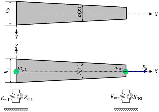
Figure 1.
Geometry of elastically restrained tapered beam with concentrated mass and axial loading.
The cross-sectional shapes varying along the length of the beam can be defined by
where , and is a nondimensional length coordinate. and denote the area and moment of inertia, respectively, at = 0. There are = 1 and = 2 for the single-tapered and double-tapered beams, respectively.
The differential equation of motion from Hamilton’s principle, considering the kinetic and strain energies, is given by:
The bending moment and shear force at the end of the beam must be balanced by the sum of the resisting forces, such as the linear springs and mass. Therefore, the following relationships can be determined using previous techniques [45,47]:
Bending moment,
and shear force,
where the terms on the right side of Equations (5) and (6) represent the bending moment and shear force of the beam at the joint, respectively, and the left-hand terms represent the resistance forces generated by the elastic supports and mass. for the left end and for the right end of a tapered beam. In addition, , , and are , , and for the left end, and , , and for the right end of a tapered beam, respectively.
The boundary conditions at the joint between the beam and the elastic support can be obtained because the sum of the forces at the joint must be zero.
These conditions are at = 0:
and
where and are the bending moment and shear force at = 0, respectively, at = 0.
At = 1:
and
where and are the bending moment and shear force at = 1, respectively, at = 1.
Eventually, the bending moments and shear forces at both ends become zero. When considering the free–free end conditions, Equations (7)–(10) can be adopted for the bending moments and shear forces at both ends. This differs from previous studies [30,31] and simplifies the process.
Assuming the harmonic oscillation has an angular frequency (),
where is the amplitude of .
By substituting Equations (3) and (11) into the differential equation, the nondimensional form of Equation (4) can be rewritten as follows:
where,
For = 1, the nondimensional differential equation of a single tapered beam is given by
where , , , , , .
The solution of Equation (14) can be assumed by
By substituting Equation (15) into Equation (14), the indicial equation is determined as
and the recurrence relationship can be obtained as
The Frobenius coefficients are as follows:
The bending moment and shear force, obtained by substituting Equations (11) and (15) into Equations (7) and (9) can be rewritten as follows:
where .
For = 2, the nondimensional differential equation of a double-tapered beam is given by
where , , , , , , .
By substituting Equation (15) into Equation (21), the indicial equation for = 2 becomes Equation (16) for = 1, and the recurrence relationship can be obtained as:
The Frobenius coefficients are as follows:
The bending moment and shear force obtained by substituting Equations (11) and (15) into Equations (8) and (10) can be rewritten as follows:
where .
The bending displacement with respect to the four roots of the initial equation can be defined as
where
The slope of the deformation curve can be obtained by differentiating the bending displacement:
The expressions for the bending displacement and the slope defined in Equations (26) and (28) can be utilized for = 1 and = 2, respectively.
The nondimensional length coordinates of the beam are = 0 and = 1 at the left- and right-hand endpoints, respectively. The state vectors at = 0 and = 1 can be determined by substituting = 0 and = 1 into the displacements and forces for = 1 and = 2, respectively, and the state vectors at = 0 for = 1 and = 2 can be expressed in matrix form as follows:
where , , and the components of matrix for = 1 can be defined as
and for = 2,
The constant can be obtained as
The state vector at = 1 for = 1 and = 2 can be expressed in matrix form as follows:
where , and the components of the matrix for = 1 can be defined as
and for = 2,
From Equations (32) and (33), the relationship between and is obtained as follows:
where , and is the transfer matrix of a beam element.
By applying the free–free end condition in Equation (36), the natural frequencies and mode shapes of the elastically restrained tapered Rayleigh beams can be calculated. , , , and in the free–free end conditions are zero. The clamped end condition can be expressed by adjusting the spring constants related to the elastic supports. The spring values for this end condition are investigated in detail in the results and discussion section. The dynamic characteristics of tapered beams utilizing a single element can be evaluated by considering the effects of the axial loading, concentrated mass, and elastic supports at both ends. In addition, to evaluate the effects between ends, they can be assembled generally as a transfer matrix. The frequency determinant for the free–free end condition can be obtained as follows:
At = 0 and = 1,
By substituting Equation (37) into Equation (36),
and the frequency determinant for the free-free end condition is expressed as
Assuming that the bending displacement () is 1, the slope of the deformation curve can be defined as
Therefore, the state vector is given by
By substituting Equation (41) into Equation (32), constant can be computed. Therefore, the modal shapes can be calculated with Equation (26).
3. Results and Discussion
The method presented here was utilized to analyze the effects of elastic supports, concentrated mass, and axial loading on the eigenpairs of tapered beams. Because this study did not consider the effect of shear deformation, its application was limited. A study on the Timoshenko beam theory to enhance the effectiveness of the applications is additionally required, but the proposed numerical method can be a useful numerical tool for analyzing many problems in which completely fixed conditions cannot be given. To demonstrate the method’s efficiency, the diverse examples illustrated in Figure 2 were considered, and the dynamic characteristics of the tapered beams were analyzed by providing various environments for these four types. The method’s accuracy was demonstrated by comparing the predicted results with those obtained in previous studies [4,16,48]. However, the comparison results were somewhat limited, as no literature was found that simultaneously considered the various effects. Therefore, the results were compared with those obtained via a commercial finite element analysis program (ANSYS).
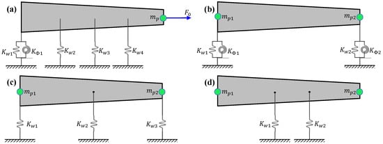
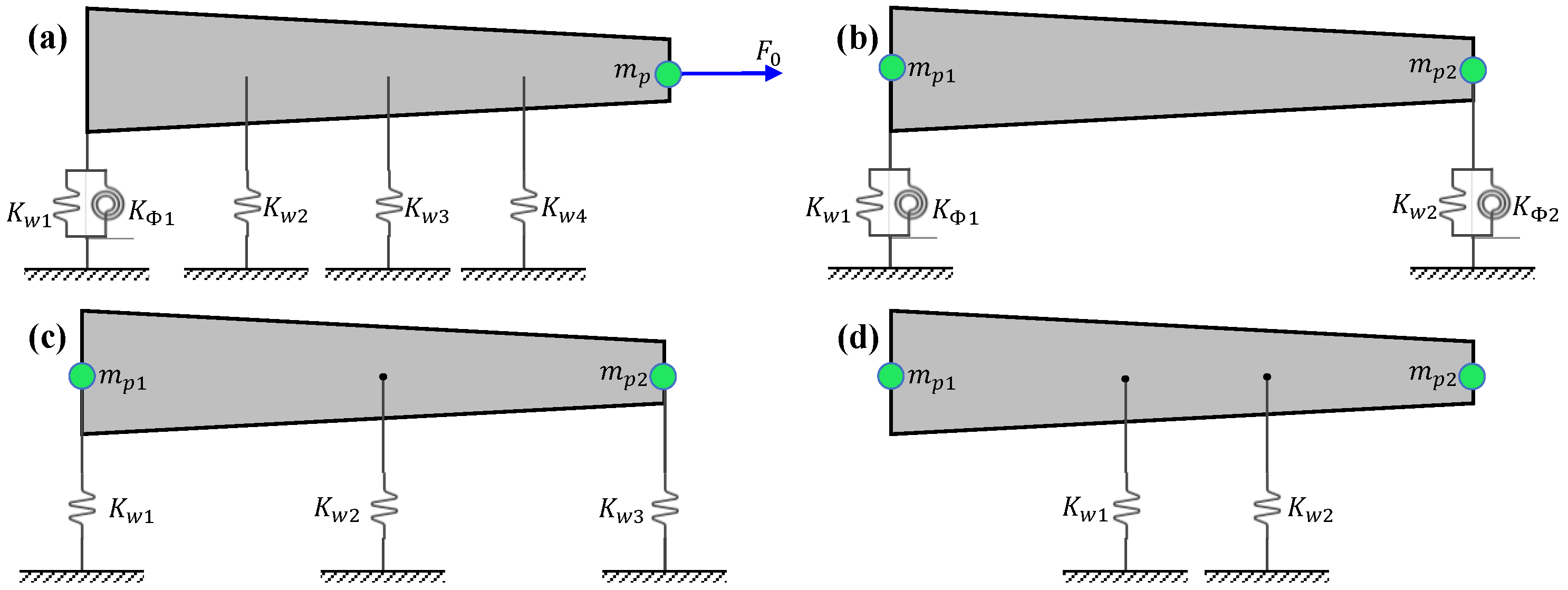
Figure 2.
Beam types utilized to consider various conditions: (a) Type A, (b) Type B, (c) Type C, and (d) Type D.
3.1. Effects of Elastic Supports
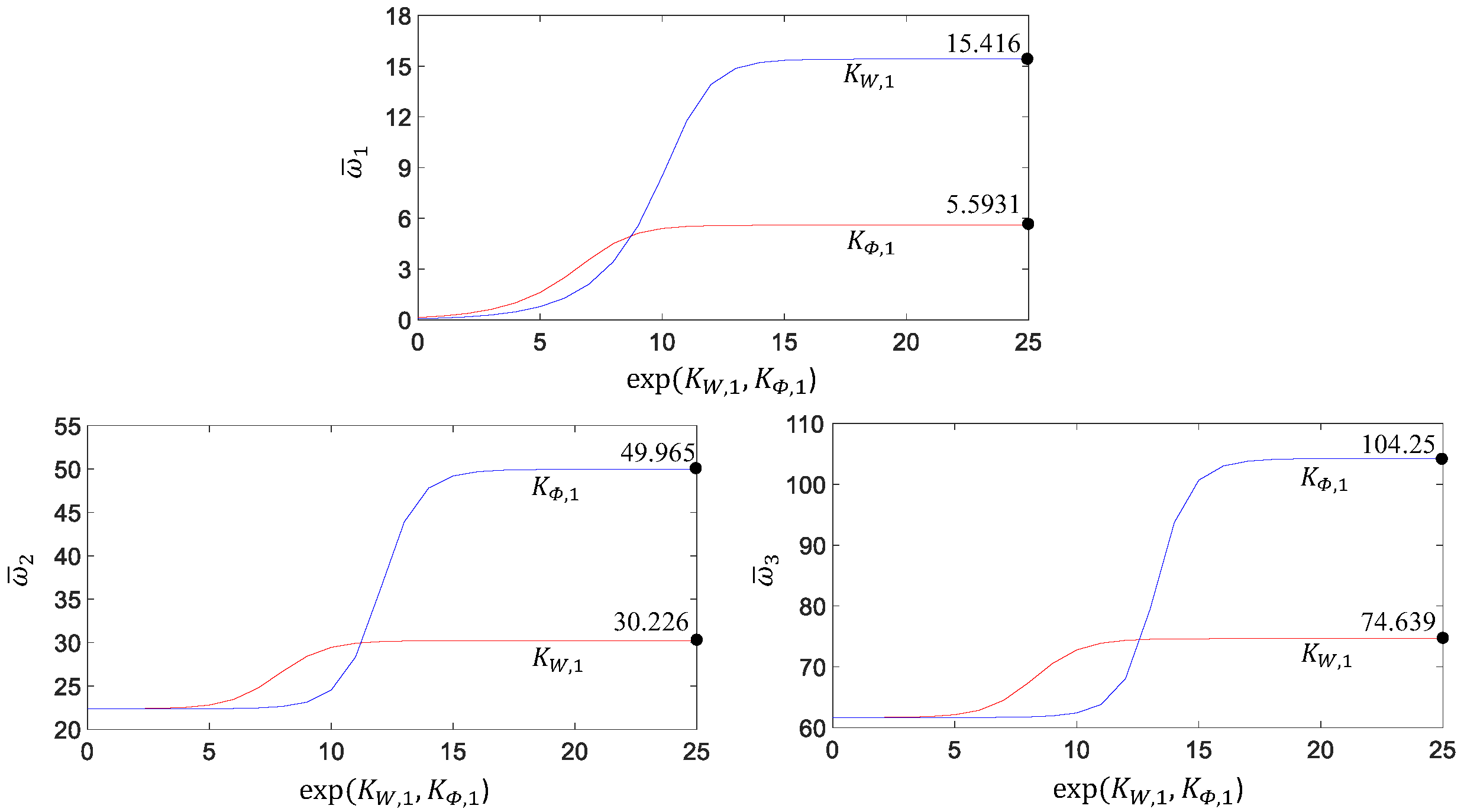
Various conditions for elastic support can be evaluated according to the change in spring values. However, the spring values required to provide a clamped condition were examined. The rotational spring or translational spring, in the absence of axial loading and concentrated mass, increased from exp(0) to exp(25); the results are presented in Figure 3. The properties of the beam were considered as follows:
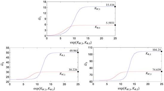
Figure 3.
Variation of nondimensional natural frequency with respect to increase of spring value.
Example 1.
= 200 GPa,
= 7850 kg/m3,
= 0.01 m,
= 0.03 m, and
= 0.8 m.
The first three nondimensional natural frequencies were examined. The spring values required for convergence to the clamped condition differed according to the order of natural frequency. = 9.745 109 (=exp(23)) N/m and = 1.319 109 (=exp(21)) Nm/rad were required for the analysis up to the first third of the natural frequency. The results presented in Figure 3 are obtained by increasing only one spring when = 0. increased only the rotational spring value, and increased only the translational spring value. The number of terms in the power series required to calculate the natural frequency was analyzed in detail in a previous study [49].
The results obtained here and in previous studies were compared [48]. The properties employed to compare the results are as follows: = 0, = 69.79 GPa, = 2600 kg/m3, = 0.025 m, = 0.05 m, = 0.996 m, = 26.5 MN/m, and = 150 kNm/rad. To demonstrate the accuracy of the proposed method, the elastic supports attached at = 0 were examined, and the effect of the elastic support attached at = 1 was analyzed. The comparison results are presented in Table 1 and have good agreement for = 1 and = 2. As the comparison results were for uniform beams, the results for = 1 and = 2 were the same.

Table 1.
Comparison of results calculated between present and previous studies.
3.2. Effects of the Concentrated Mass
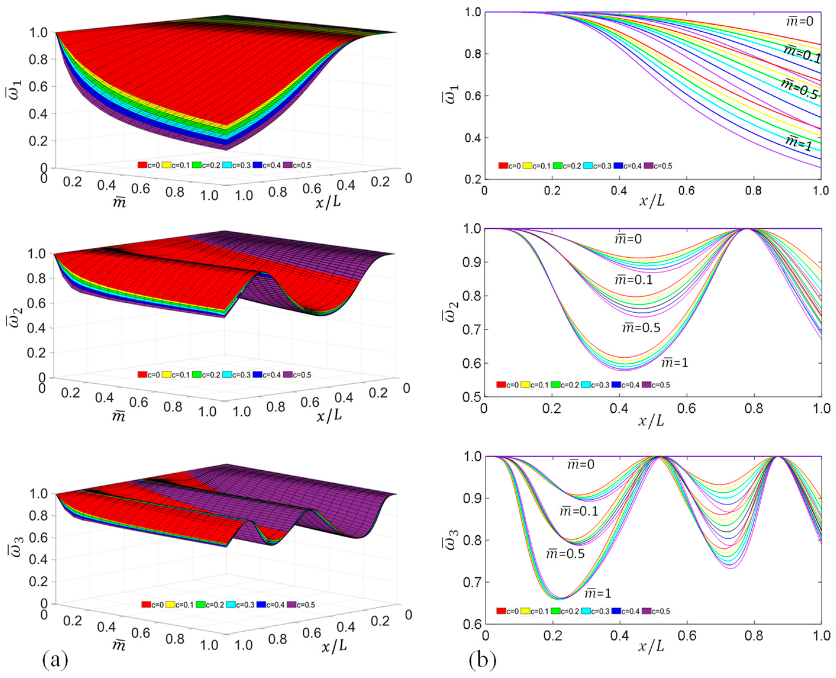
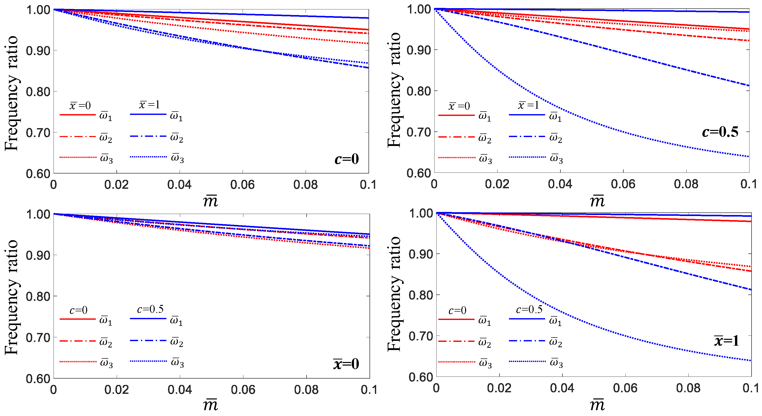
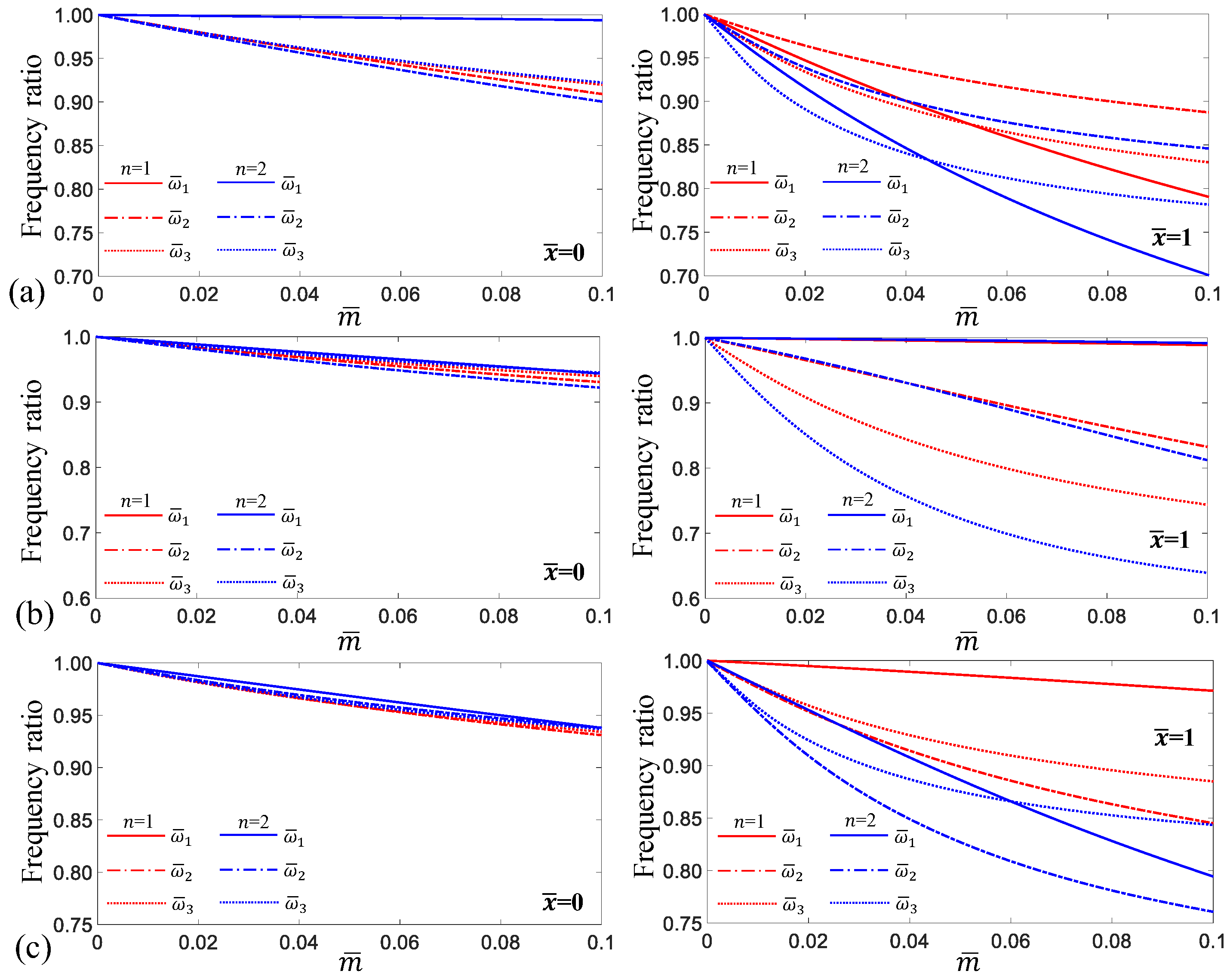
To analyze the effect of the taper ratio on the natural frequency of a cantilever beam with a concentrated mass, the effects of the concentrated mass and taper ratios on the natural frequencies of such beams were investigated for = 1 and = 2. The mass of the beam for = 0 and 1.884 kg was considered the concentrated mass, and the ratio of the concentrated mass to the beam mass was added at arbitrary positions along the length of the beam from 0 to 1 at intervals of 0.1. The taper ratio ranged from 0 to 0.5, and the predicted results are shown in Figure 4 and Figure 5. These figures show the effects of the concentrated mass on the natural frequencies of the single- and double-tapered beams under clamped free-end conditions. Figure 4a and Figure 5a show the variations in the natural frequencies with respect to changes in the position of the entire considered concentrated mass, and Figure 4b and Figure 5b show the results for = 0, 0.1, 0.5, and 1. As shown in Figure 4b and Figure 5b, the larger the taper ratio and , the greater the effect of the concentrated mass.
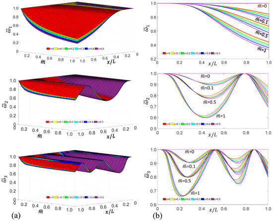
Figure 4.
Effects of the concentrated mass on the first three natural frequencies of single tapered beams with the cantilevered end condition: (a) results for entire concentrated masses, and (b) results for = 0, 0.1, 0.5, and 1.

Figure 5.
Effects of the concentrated mass on the first three natural frequencies of double tapered beams with the cantilevered end condition: (a) results for entire concentrated masses, and (b) results for = 0, 0.1, 0.5, and 1.
In the case of the second natural frequency, the positional changes at the nodal point according to the changes in the size and location of the concentrated mass were not pronounced, whereas the third natural frequency showed a noticeable change in the location of the first nodal point. When analyzing the results of Figure 4b and Figure 5b, the effect of the concentrated mass on the natural frequencies for = 1 and = 2 changed with a similar trend. As expected, in the case of the first natural frequency, the larger the taper ratio at all positions, the greater the effect of the concentrated mass. However, the second and third natural frequencies showed a greater effect for = 0 than for = 0.5 at some locations, and the location of the occurrence of this phenomenon depended on the size of the concentrated mass.
Among the results depicted in Figure 4b and Figure 5b, the natural frequencies of tapered cantilever beams with = 0.1 at arbitrary locations are presented in Table 2 and Table 3. Table 2 lists the results for = 1 when the C-F end condition is applied, and Table 3 lists the results for = 2. The results for = 1 and = 2 with = 0.1 as a function of location are compared in Figure 6. The nodal points shifted to the right as the taper ratio increased, and the difference between = 1 and = 2 was not significant.
Table 2.
Effects of the point mass on the first three nondimensional natural frequencies of single tapered cantilever beams as a function of location when = 0.1.
Table 3.
Effects of the point mass on the first three nondimensional natural frequencies of double tapered cantilever beams as a function of location when = 0.1.
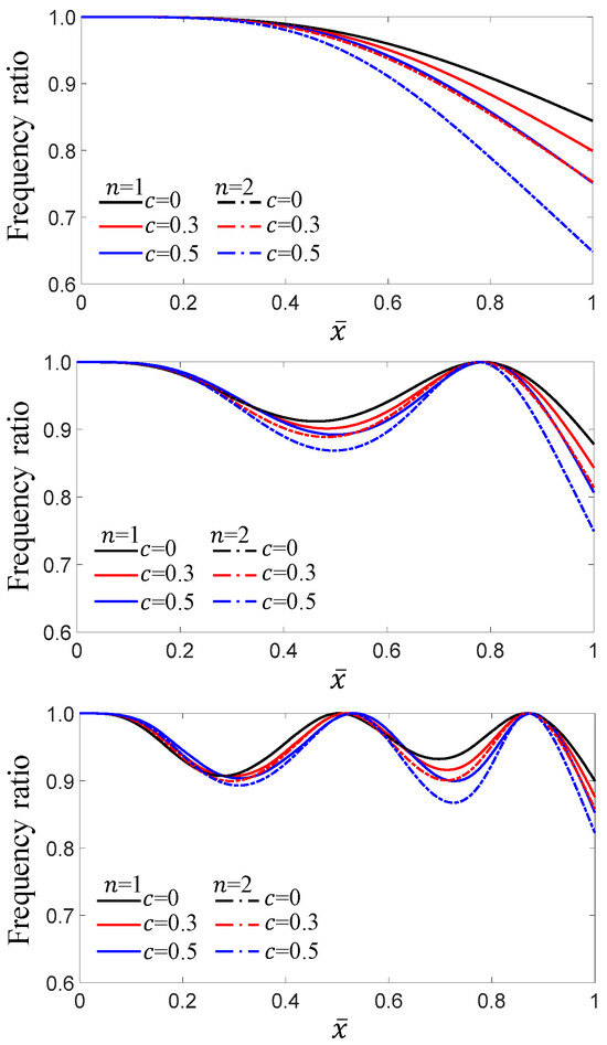
Figure 6.
Comparison of natural frequencies for = 1 and = 2 when having = 0.1 at the arbitrary location.
The accuracy of the predicted results for the concentrated mass was demonstrated by comparing the results with those of previous studies [16]. The values of the translational and rotational springs used to provide a clamped-end condition were = 9.745 109 N/m and = 1.319 109 Nm/rad. The effect of concentrated mass on the first three nondimensional natural frequencies of a clamped-free uniform beam with a concentrated mass attached to the free end. When considering from 0 to 1.0 at intervals of 0.2, a taper ratio of = 10−4 was used for the uniform beam. The comparison results are presented in Table 4 and are in good agreement. BE and = 0 shown in Table 4 are the results computed by classical beam theory, and ≠ 0 is the result calculated by Rayleigh beam theory for Example 1.
Table 4.
Comparisons of the first three nondimensional natural frequencies of a clamped-free uniform beam with a concentrated mass at the free end.
3.3. Effects of Concentrated Mass Attached to Elastic Supports
To analyze the effects of the concentrated mass attached to the elastic supports under the same conditions, the rotational and translational springs at both ends used the same values of 22,026.5 (=exp(10)) for all cases. The Type B model shown in Figure 2 is considered, and the 12 cases are as follows: Cases A1–A4 are supported by and at = 0, and Cases A5–A8 are supported by and at = 0 and at = 1. In addition, Cases A9–A12 are beam models supported by and at = 0, and and at = 1. These values were listed in Table 5, and the concentrated mass is increased from 0 to 0.1 in intervals of 0.01, and the taper ratio is considered = 0 and = 0.5 for each case. The predicted results for the first three nondimensional natural frequencies of the single- and double-tapered beams are tabulated in Table 6 and Table 7, respectively.
Table 5.
Values of , , and attached to Example 1.
Table 6.
Effects of the concentrated mass attached to elastic supports on the natural frequencies when = 1.
Table 7.
Effects of the concentrated mass attached to elastic supports on the natural frequencies when n = 2.
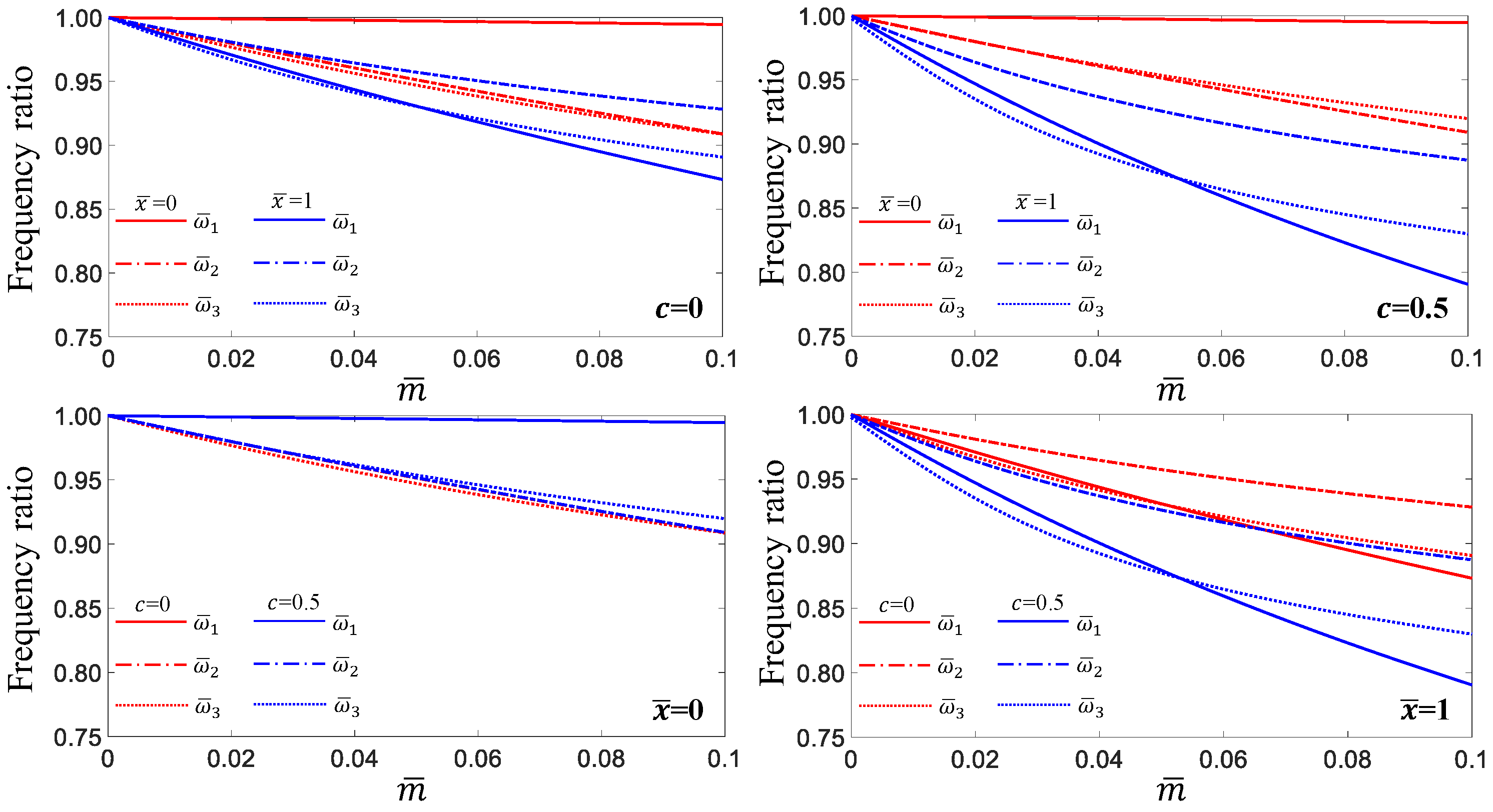
The effects of the concentrated mass and taper ratio for Cases A1–A4 with = 1 are illustrated in Figure 7 to compare the effect of the concentrated mass at = 0 and = 1 and to analyze the effect of the taper ratio. As shown in Figure 7, the first and third natural frequencies of the uniform beams were more affected than those when attached at = 1, and these effects on the second natural frequency were large at = 0. For tapered beams with = 0.5, the first three natural frequencies were affected more by the concentrated mass attached at = 1 than that at = 0. When comparing the effects of the taper ratio, the first and second natural frequencies had similar effects, regardless of the taper ratio, when the concentrated mass was attached to the elastic supports. The effect of the taper ratio on the third natural frequency was slightly larger than that of the first two frequencies. However, these frequencies were significantly affected by the taper ratio when a concentrated mass was attached to the free end.
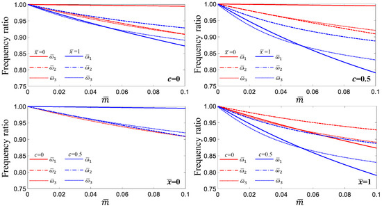
Figure 7.
Effects of the concentrated mass and taper ratios on the first three natural frequencies of = 1: Cases A1–A4.
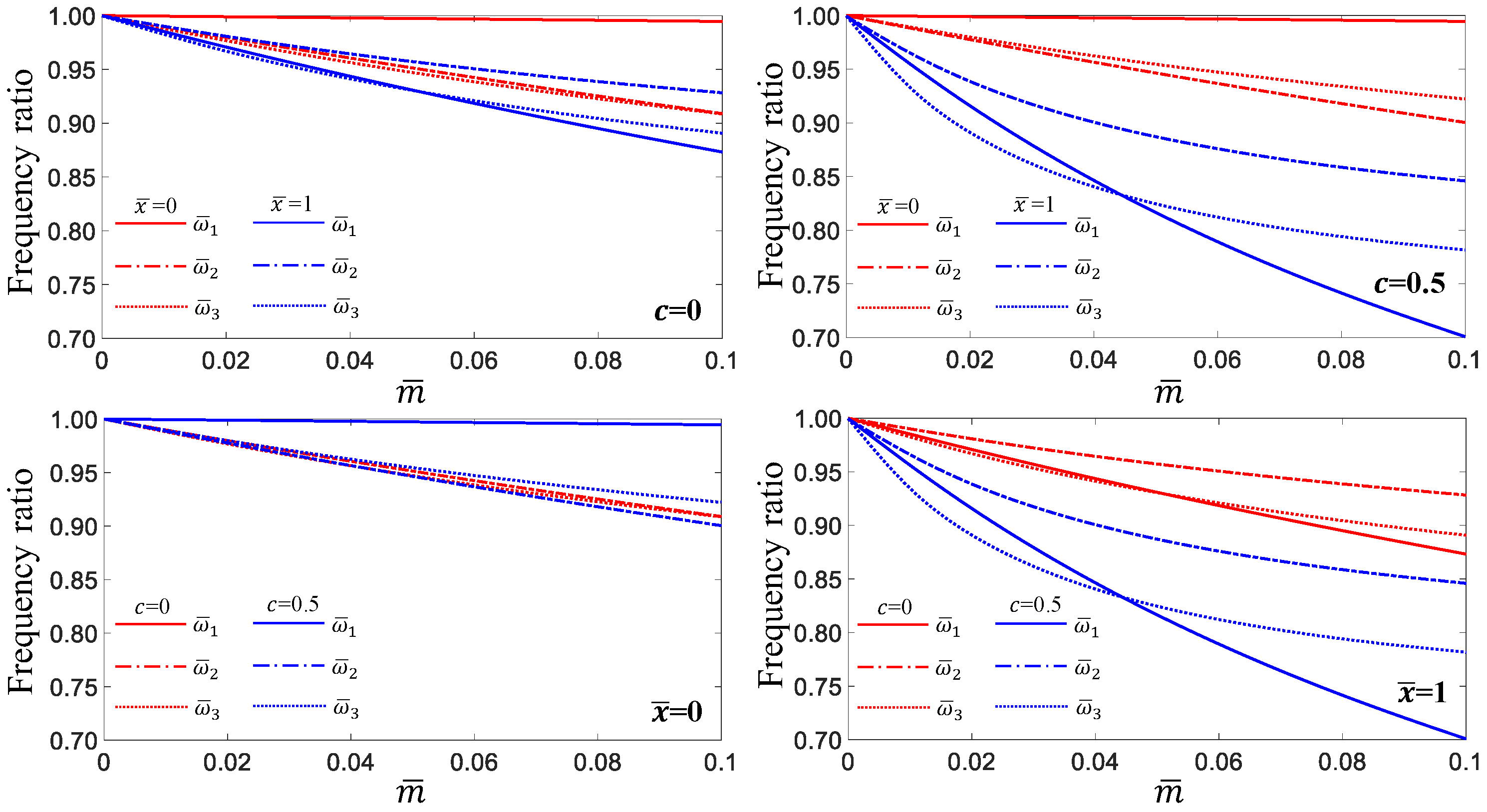
The effects of the concentrated mass and taper ratio for Cases A5–A8 with = 1 are illustrated in Figure 8. The concentrated mass attached at = 0 significantly affected the first natural frequency for c = 0 and c = 0.5, whereas the second and third natural frequencies were significantly affected when the concentrated mass was located at = 1. When comparing the taper ratios, the first natural frequency had a similar effect, regardless of the taper ratio, when the concentrated mass was located at = 0. The second and third natural frequencies showed clear differences based on the effect of the taper ratio. The natural frequencies of a single tapered beam with a concentrated mass at = 1 showed a large difference owing to the effect of the taper ratio, and the third natural frequency compared to other frequencies was most affected by the taper ratio.
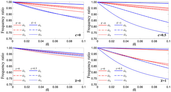
Figure 8.
Effects of the concentrated mass and taper ratios on the first three natural frequencies of = 1 with respect to Cases A5–A8.
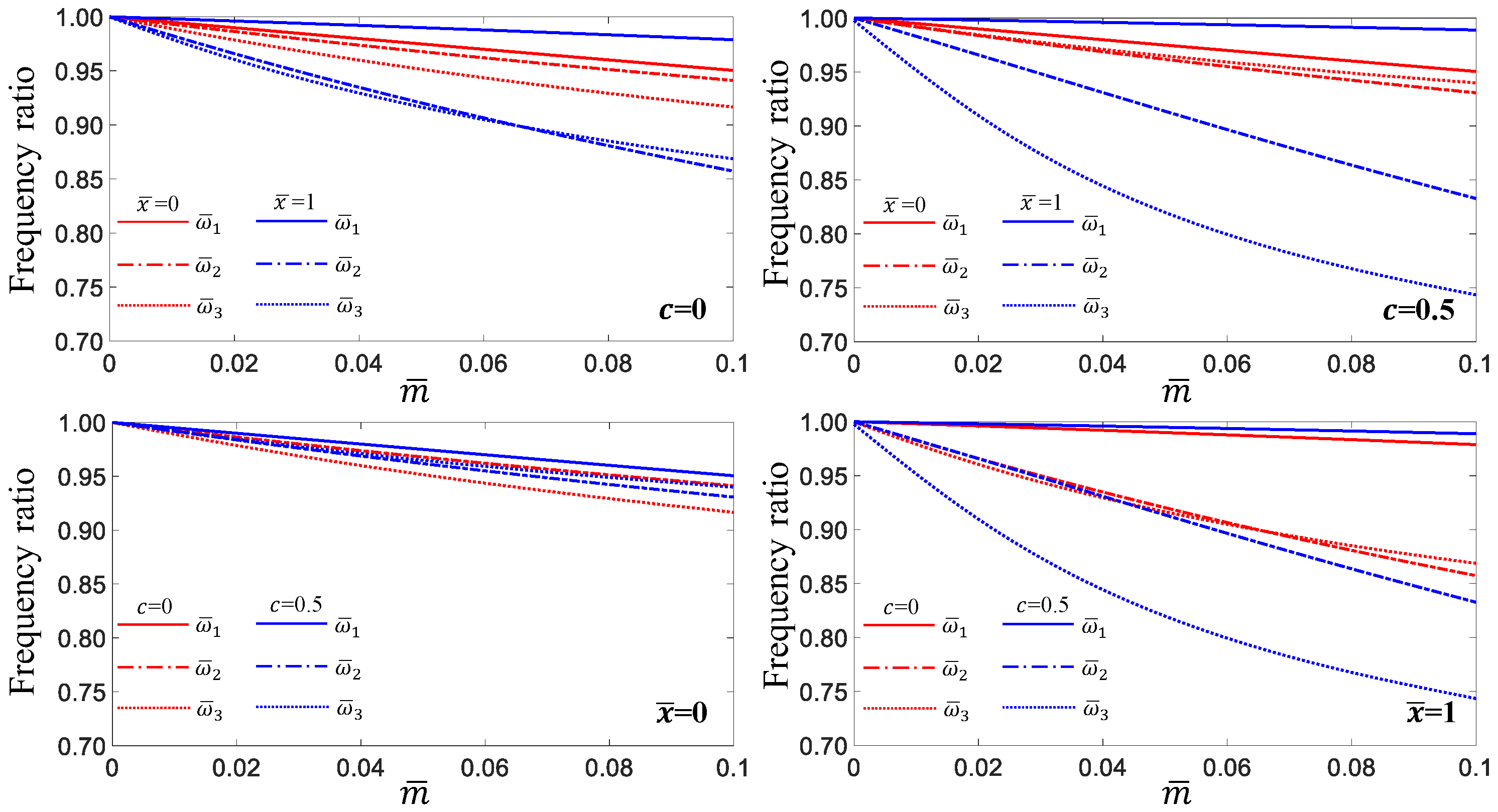
The effects of the concentrated mass and taper ratio for Cases A9–A12 with = 1 are presented in Figure 9. When c = 0.5, the first natural frequency was more affected by the concentrated mass at = 0 than at = 1, and the fundamental frequencies for both = 0 and = 0.5 exhibited a similar effect at = 0. The effect of the taper ratio on these frequencies was greater when the concentrated mass was located at = 1 than at = 0.
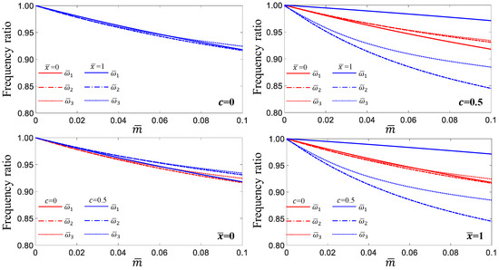
Figure 9.
Effects of the concentrated mass and taper ratios on the first three natural frequencies of = 1 with respect to Cases A9–A12.
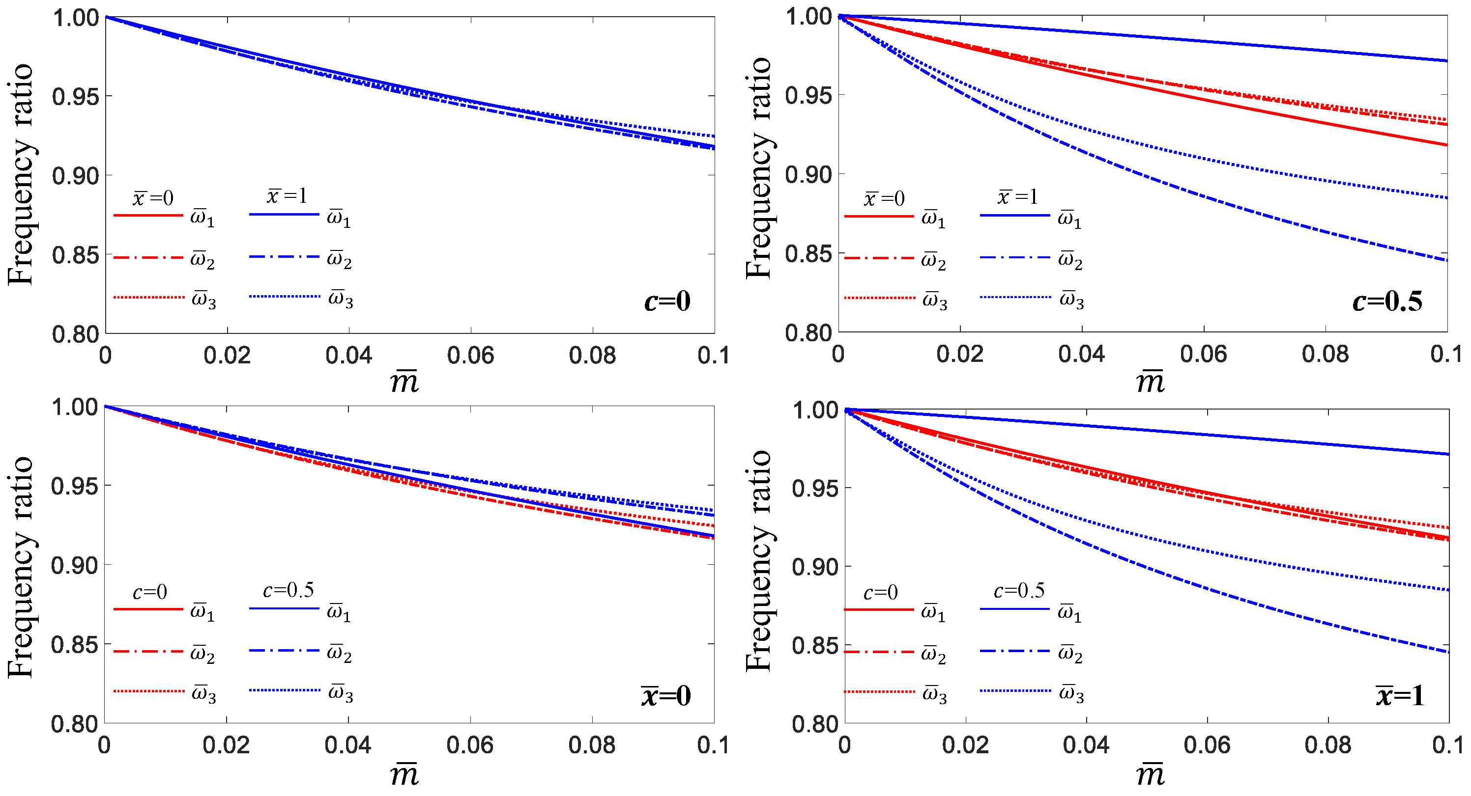
The effects of the concentrated mass and taper ratio for Cases A1–A12 with = 2 are shown in Figure 10, Figure 11 and Figure 12. The results for Cases A1–A8 for = 2, as illustrated in Figure 10 and Figure 11, present a similar trend to those for Cases A1–A8 for = 1, as illustrated in Figure 7 and Figure 8. In addition, when comparing the results illustrated in Figure 9 and Figure 12, the results for Cases 9–11 exhibited a similar trend between = 1 and = 2; however, the fundamental frequency of tapered beams with = 0.5 for Case A12 had a large difference compared to those for Case A12 with = 1. The first natural frequency is more strongly influenced by the taper ratio when the concentrated mass is located at = 1 than at = 0. The results indicate that the effect of the taper ratio was significant when a concentrated mass was attached at = 1.
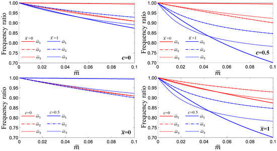
Figure 10.
Effects of the concentrated mass and taper ratios on the first three natural frequencies of = 2 with respect to Cases A1–A4.
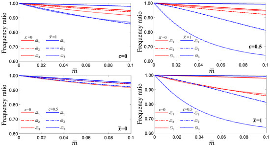
Figure 11.
Effects of the concentrated mass and taper ratios on the first three natural frequencies of = 2 with respect to Cases A5–A8.
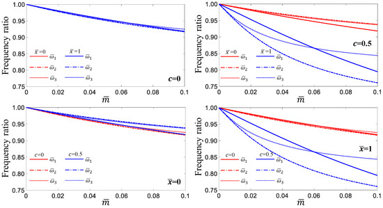
Figure 12.
Effects of the concentrated mass and taper ratios on the first three natural frequencies of = 2: Cases A9–A12.
To compare the results for the single- and double-tapered beams with = 0.5, the computed results are presented in Figure 13. As shown in Figure 13, the fundamental frequencies of the single- and double-tapered beams with = 0.5 have almost the same value when the concentrated mass is located at = 0. The second and third natural frequencies showed a small difference compared with the effect of the concentrated mass attached at = 1. Except for the fundamental frequencies in cases A7 and A8, the natural frequencies for = 2 than = 1 were affected more by the taper ratio when the concentrated mass was attached at = 1 than when it was attached at = 0. The first natural frequency for Case A12 exhibited the most significant difference among all results.
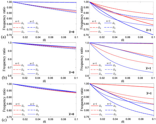
Figure 13.
Comparison of = 1 and = 2 for effects of the concentrated mass on the first three natural frequencies when c = 0.5: (a) Cases A3 and A4, (b) Cases A7 and A8, and (c) Cases A11 and A12.
3.4. Effect of Axial Loading on Elastic Supports
The natural frequencies of the elastically restrained tapered beams under axial loading were first investigated, and some of the results computed for Example 1 were compared with those analyzed in a previous study [4]. The results of the comparison between the proposed method and those of previous studies are presented in Table 8. The beam model had elastic supports ( = 9.745 109 N/m and = 1.319 109 Nm/rad) at = 0, and a free-end condition at = l. The axial loading at the free end was assumed. The comparison results agreed well with each other, as illustrated in Table 8; however, the first natural frequency under compressive loading could not be found at a value similar to that of the buckling load [50]. It is a well-known fact that a compressive load decreases the natural frequency and a tensile load increases the natural frequency [51].
Table 8.
First three nondimensional natural frequencies of uniform cantilever beams with the axial loading.
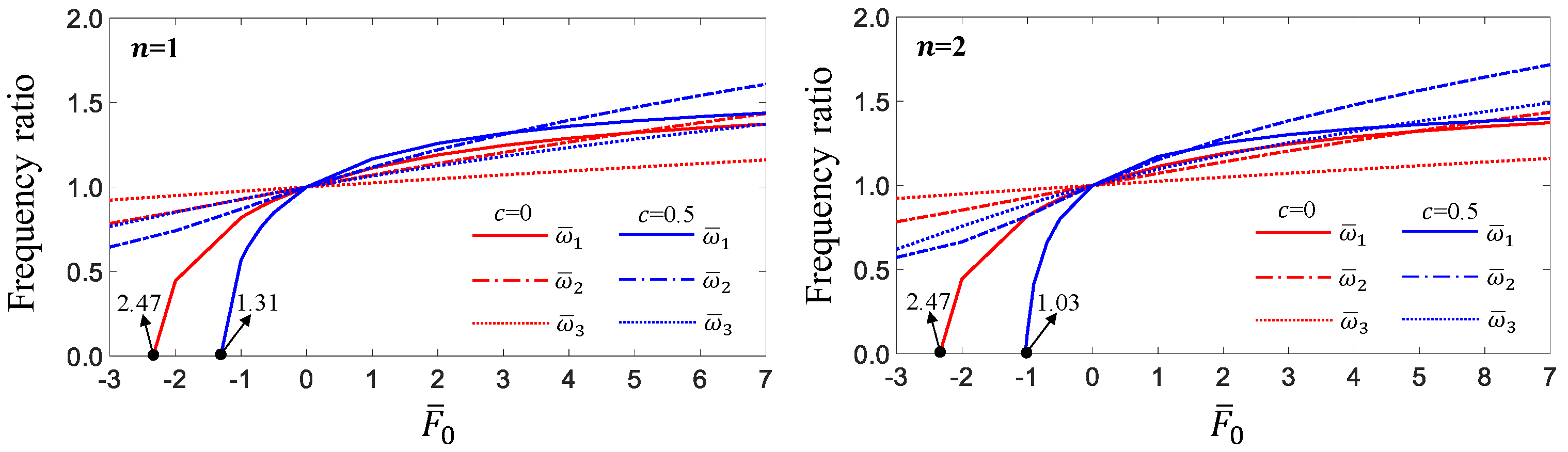
To investigate the effect of axial loading on the natural frequencies of elastically restrained tapered beams, the values of the translational and rotational springs at = 0 are considered as = 22,026.5 N/m and = 22,026.5 Nm/rad, and the computed results are tabulated in Table 9. The compressive loading value at which the first natural frequency vanished differed because of the effect of the taper ratio. As illustrated in Figure 14, these values exhibited significant differences when comparing uniform beams and tapered beams with = 0.5 and were also different for single- and double-tapered beams with = 0.5. Therefore, the effect of elastic supports on the first natural frequency under compressive loading was analyzed.
Table 9.
First three nondimensional natural frequencies of elastically restrained tapered beams with the axial loading.
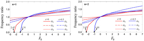
Figure 14.
Effects of the axial loading on the first three natural frequencies of elastically restrained tapered beam.
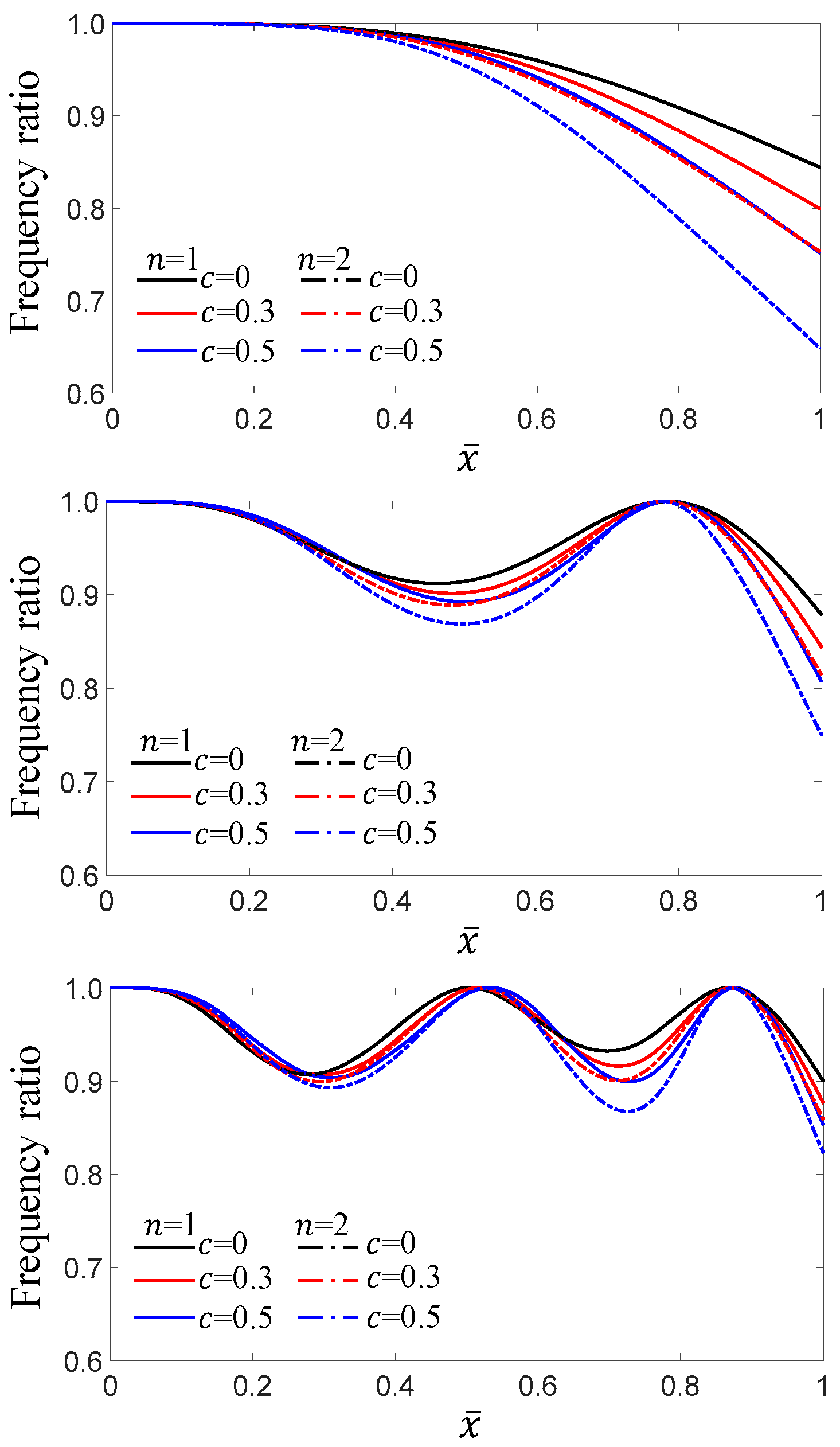
The compressive load at which the first natural frequency vanished was investigated as a function of the elastic spring value. It was assumed that the first natural frequency vanished when it was less than = 1 rad/s; the results are presented in Figure 15. Because numerous parameter studies are required, it is assumed that the translational and rotational springs vary by the same values. As illustrated in Figure 15, the compressive load at which the first natural frequency vanished varied significantly depending on the taper ratio. At values below exp(6), it exhibited similar compressive load values, regardless of the taper ratio. For elastic springs with a value of exp(6) or less, the compressive loading at which the first natural frequency vanished was almost identical, regardless of the taper ratio. It converges at values greater than exp(14), and the effect is greater at = 2 than at = 1.
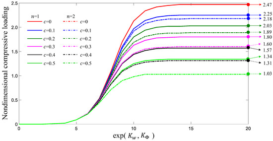
Figure 15.
Relationships between compressive loadings and values of elastic springs at which the first natural frequency vanished.
3.5. Effects of the Combination of Axial Loading, Concentrated Mass, and Elastic Supports
In this section, various environments that can cause variations in natural frequencies are addressed. Variations in the natural frequencies of tapered beams for combinations of multiple elastic supports, concentrated masses, and axial forces were investigated, and Types A, C, and D, as illustrated in Figure 2, were considered to analyze these effects. The values of , , , and used to construct the various problems are presented in Table 10. Type A considers the effects of elastic supports, axial loading, and concentrated masses on the eigenpairs of single- and double-tapered beams. Types C and D consider the effects of the point mass and multiple elastic supports on the natural frequencies of such beams.
Table 10.
Values for , , , and attached to Example 1.
Before analyzing the example beams, the computed results were compared with the natural frequencies obtained using a commercial finite element analysis program (ANSYS). The comparison results are presented in Table 11 and agree with each other. Because the comparative results demonstrated that the proposed method has excellent accuracy even for complex problems, the eigenvalues predicted by considering several cases that can be experienced in practical problems were analyzed. The results are summarized in Table 12. As various analyses were conducted, the variations in the mode shapes of these effects were investigated.
Table 11.
Comparisons of the results computed from the present method and ANSYS.
Table 12.
First three nondimensional natural frequencies computed for Type A, Type C, and Type D.
As illustrated in Figure 16, the first three mode shapes for the three cases of Type A with = 0.5 were compared with the mode shapes of a cantilever beam for = 1 and = 2. When the same elastic support or concentrated mass was attached to = 1 rather than = 2, the effect on the modal shapes was greater. Compared with the elastic support, the effect of the concentrated mass attached at = 1 appeared to be significantly greater. The effect of the axial load on the mode shape is greater for = 2 than for = 1. When analyzing the second and third modes, the nodal point was moved to the left by the effects of the axial load and elastic support, whereas it was moved to the right by the effect of the concentrated mass.
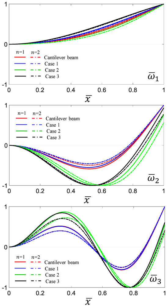
Figure 16.
Variation in the first three mode shapes of tapered beams for Type A.
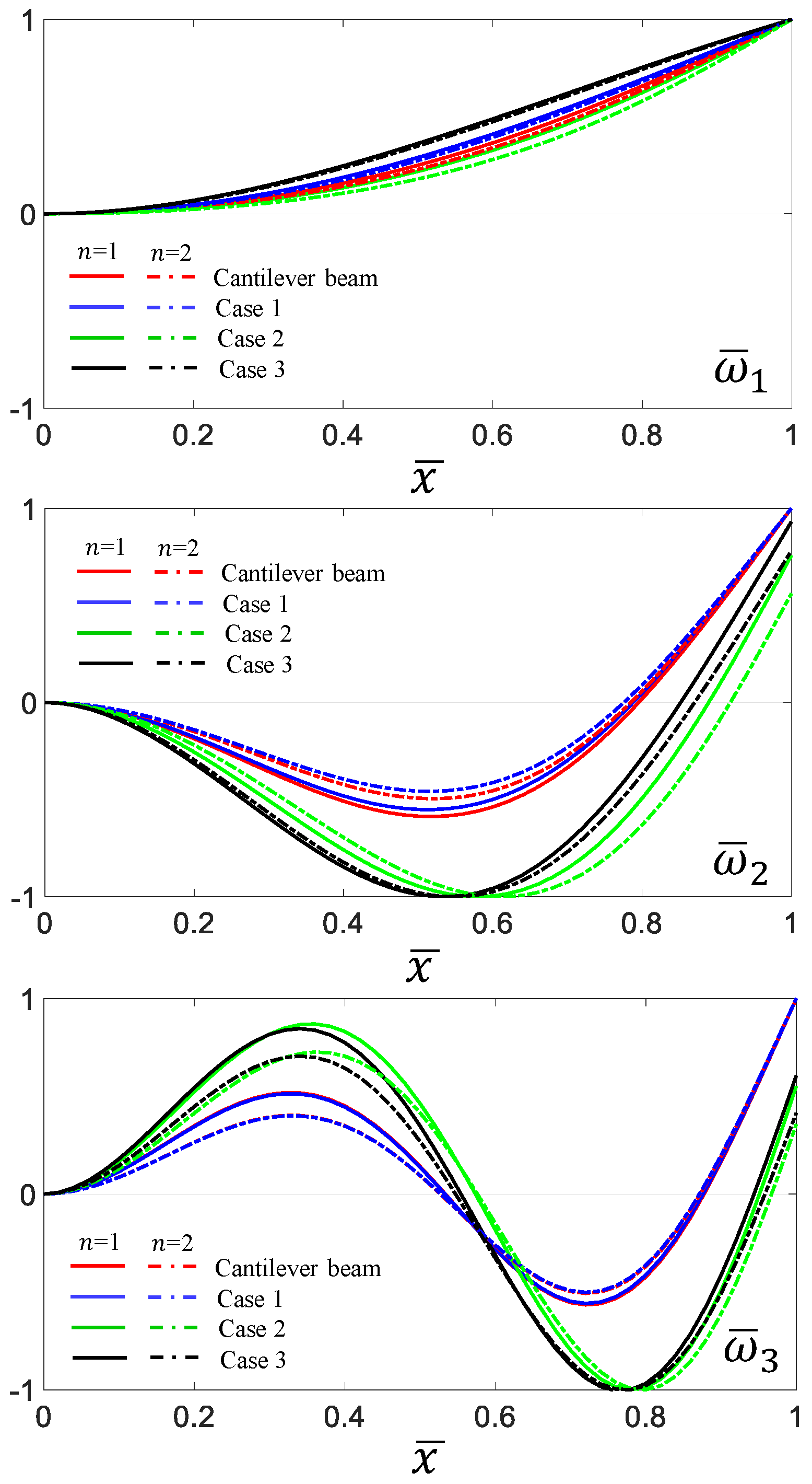
Finally, the effects of the elastic supports on the first three mode shapes of uniform beams, single- and double-tapered beams with = 0.5, and elastically restrained cantilever beams were considered. As illustrated in Figure 17, when the spring values increase, the bending displacement at the support point converges to zero. Compared with the tapered beams, the effect of the elastic supports on the mode shapes was more significant for the uniform beams. The mode shapes of the single- and double-tapered beams changed with a similar trend; however, the effect of the elastic support was slightly greater for = 1 than for = 2. The values of the elastic springs and natural frequencies used to plot the mode shapes are presented in Table 13; the values of the rotational and translational springs increased with the same value.
Figure 17.
Effects of the elastic supports on the first three mode shapes of uniform beams and single and double tapered beams having = 0.5.
Table 13.
First three natural frequencies of elastically restrained beams relative to the increase in spring values.
The numerical method presented in this study can be adopted to analyze the variation in the dynamic characteristics of elastically restrained tapered beams with axial loading and concentrated mass. The critical buckling load for the first mode of the beams, which is calculated by considering the taper ratios and elastic boundary conditions, can serve as a useful criterion for the dynamic analysis of structures such as columns and beams. In addition, the analyzed results can be applied to the engineering design of beam-like structures with elastic supports.
4. Conclusions
A new and simple numerical method was developed to analyze the effects of concentrated masses, axial loading, and elastic supports on the eigenpairs of single- and double-tapered beams. The shear force and bending moment were determined by considering the equilibrium equation, in which the sum of the forces at the joint of the elastic support and beam as well as at arbitrary positions becomes zero. Based on this assumption, a free-free condition was established at both ends, and the displacements and forces of the tapered beam were determined using a simple procedure. The displacements and forces of the tapered-beam model were determined. The effectiveness of the proposed method was demonstrated by computing the results, considering diverse examples that can be experienced in practical problems.
Moreover, the relationship between the elastic supports and compressive loading was analyzed in detail for the values of compressive loading at which the first natural frequency vanished. The compressive loading decreased depending on the taper ratio and was significantly influenced by the taper ratio. The concentrated mass significantly affects the mode shape and natural frequency, and the results analyzed through parametric studies can be used as a benchmark solution for other approaches.
Funding
This research was funded by the National Research Foundation of Korea (Grant number NRF-2021R1F1A1064233).
Institutional Review Board Statement
Not applicable.
Informed Consent Statement
Not applicable.
Data Availability Statement
Not applicable.
Acknowledgments
The author gratefully acknowledges the financial support for this research from the National Research Foundation of Korea (Grant number NRF-2021R1F1A1064233).
Conflicts of Interest
The author declares no conflict of interest.
References
- Wei, H.; Pan, Q.X.; Adetoro, O.B.; Avital, E.; Yuan, Y.; Wen, P.H. Dynamic large deformation analysis of a cantilever beam. Math. Comput. Simul. 2020, 174, 183–204. [Google Scholar] [CrossRef]
- Sibtain, M.; Yee, K.; Ong, O.Z.S.; Ghayesh, M.H.; Amabili, M. Dynamics of size-dependent multilayered shear deformable microbeams with axially functionally graded core and non-uniform mass supported by an intermediate elastic support. Eng. Anal. Bound. Elem. 2023, 146, 263–283. [Google Scholar] [CrossRef]
- De Rosa, M.A.; Lippiello, M. Closed-form solutions for vibrations analysis of cracked Timoshenko beams on elastic medium: An analytically approach. Eng. Struct. 2021, 236, 111946. [Google Scholar] [CrossRef]
- Li, X.F.; Tang, A.A.; Xi, L.Y. Vibration of a Rayleigh cantilever beam with axial force and tip mass. J. Constr. Steel. Res. 2013, 80, 15–22. [Google Scholar] [CrossRef]
- Yesilce, Y. Differential transform method and numerical assembly technique for free vibration analysis of the axial-loaded Timoshenko multiple-step beam carrying a number of intermediate lumped masses and rotary inertias. Struct. Eng. Mech. 2015, 53, 537–573. [Google Scholar] [CrossRef]
- Demirdag, O.; Yesilce, Y. Solution of free vibration equation of elastically supported Timoshenko columns with a tip mass by differential transform method. Adv. Eng. Softw. 2011, 42, 860–867. [Google Scholar] [CrossRef]
- Ko, Y.Y. A simplified structural model for monopile-supported offshore wind turbines with tapered towers. Renew. Energ. 2020, 156, 777–790. [Google Scholar] [CrossRef]
- Karami, G.; Malekzadeh, P.; Shahpari, S.A. A DQEM for vibration of shear deformable nonuniform beams with general boundary conditions. Eng. Struct. 2003, 25, 1169–1178. [Google Scholar] [CrossRef]
- Auciello, N.M. On the transverse vibrations of non-uniform beams with axial loads and elastically restrained ends. Int. J. Mech. Sci. 2001, 43, 193–208. [Google Scholar] [CrossRef]
- Zhou, D.; Cheung, Y.K. The free vibration of a type of tapered beams. Comput. Methods Appl. Mech. Eng. 2000, 188, 203–216. [Google Scholar] [CrossRef]
- Banerjee, J.R.; Su, H.; Jackson, D.R. Free vibration of rotating tapered beams using the dynamic stiffness method. J. Sound Vib. 2006, 298, 1034–1054. [Google Scholar] [CrossRef]
- Rajasekaran, S.; Khaniki, H.B. Bending, buckling and vibration of small-scale tapered beams. Int. J. Eng. Sci. 2017, 120, 172–188. [Google Scholar] [CrossRef]
- Banerjee, J.R.; Jackson, D.R. Free vibration of a rotating tapered Rayleigh beam: A dynamic stiffness method of solution. Comput. Struct. 2013, 124, 11–20. [Google Scholar] [CrossRef]
- Banerjee, J.R.; Ananthapuvirajah, A. Free flexural vibration of tapered beams. Comput. Struct. 2019, 224, 106106. [Google Scholar] [CrossRef]
- Boiangiu, M.; Ceausu, V.; Untaroiu, C.D. A transfer matrix method for free vibration analysis of Euler-Bernoulli beams with variable cross section. J. Vib. Control 2016, 22, 2591–2602. [Google Scholar] [CrossRef]
- Laura, P.A.A.; Pombo, J.L.; Susemihl, E.A. A note on the vibrations of a clamped-free beam with a mass at the free end. J. Sound Vib. 1974, 37, 161–168. [Google Scholar] [CrossRef]
- Auciello, N.M.; Nole, G. Vibrations of a cantilever tapered beam with varying section properties and carrying a mass at the free end. J. Sound Vib. 1998, 214, 105–119. [Google Scholar] [CrossRef]
- Sarkar, K.; Ganguli, R.; Elishakoff, I. Closed-form solutions for non-uniform axially loaded Rayleigh cantilever beams. Struct. Eng. Mech. 2016, 60, 455–470. [Google Scholar] [CrossRef]
- Bokaian, A. Natural frequencies of beams under tensile axial loads. J. Sound Vib. 1990, 142, 481–498. [Google Scholar] [CrossRef]
- Bokaian, A. Natural frequencies of beams under compressive axial loads. J. Sound Vib. 1988, 126, 49–65. [Google Scholar] [CrossRef]
- Chen, B.; Xu, Q.; Zhu, B.; Yang, Y.; Li, Y. Buckling and postbuckling behaviors of symmetric/asymmetric double-beam systems. Int. J. Mech. Sci. 2022, 235, 107712. [Google Scholar] [CrossRef]
- Zhang, Z.; Liang, C.; Kong, D.; Xiao, Z.; Zhang, C.; Chen, W. Dynamic buckling and free bending vibration of axially compressed piezoelectric semiconductor rod with surface effect. Int. J. Mech. Sci. 2023, 238, 107823. [Google Scholar] [CrossRef]
- Chen, D.; Gu, C.; Li, M.; Sun, B.; Li, X. Natural vibration characteristics determination of elastic beam with attachments based on a transfer matrix method. J. Vib. Control 2022, 28, 637–651. [Google Scholar] [CrossRef]
- Ni, Z.; Hua, H. Axial-bending coupled vibration analysis of an axially-loaded stepped multi-layered beam with arbitrary boundary conditions. Int. J. Mech. Sci. 2018, 138, 187–198. [Google Scholar] [CrossRef]
- Subrahmanyam, K.B.; Garg, A.K. Uncoupled flexural vibrations of straight beams with all possible boundary conditions treated by a transfer matrix method. J. Sound Vib. 1997, 204, 397–419. [Google Scholar] [CrossRef]
- Chen, G.; Zeng, X.; Liu, X.; Rui, X. Transfer matrix method for the free and forced vibration analyses of multi-step Timoshenko beams coupled with rigid bodies on springs. Appl. Math. Model. 2020, 87, 152–170. [Google Scholar] [CrossRef]
- Jin, Y.; Luo, X.; Liu, H.; Qiu, B.; Chi, H. An accurate solution method for vibration analysis of multi-span lattice sandwich beams under arbitrary boundary conditions. Thin-Walled Struct. 2022, 175, 109214. [Google Scholar] [CrossRef]
- Gong, Q.; Teng, Y.; Li, H.; Pang, F.; Zhang, L. Series solution for dynamical characteristic of spatial beam system structure in offshore platform. Ocean Eng. 2023, 280, 114814. [Google Scholar] [CrossRef]
- Zheng, D.; Du, J.; Liu, Y. Vibration characteristics analysis of an elastically restrained cylindrical shell with arbitrary thickness variation. Thin-Walled Struct. 2021, 165, 107930. [Google Scholar] [CrossRef]
- De Rosa, M.A.; Lippiello, M.; Maurizi, M.J.; Martin, H.D. Free vibration of elastically restrained cantilever tapered beams with concentrated viscous damping and mass. Mech. Res. Commun. 2010, 37, 261–264. [Google Scholar] [CrossRef]
- Auciello, N.M. Transverse vibrations of a linearly tapered cantilever beam with tip mass of rotary inertia and eccentricity. J. Sound Vib. 1996, 194, 25–34. [Google Scholar] [CrossRef]
- Gao, C.; Xiang, Y.; Yang, Y.; Lin, H. Transfer matrix method for analyzing dynamic response of multi-span elastically supported SFT under moving load. Appl. Math. Model. 2022, 112, 238–261. [Google Scholar] [CrossRef]
- Sun, K.; Nie, X.; Tan, T.; Yu, Z.; Yan, Z. Coupled vortex-induced modeling for spatially large-curved beam with elastic support. Int. J. Mech. Sci. 2022, 214, 106903. [Google Scholar] [CrossRef]
- Lin, S.M.; Lee, S.Y.; Wang, W.R. Dynamic analysis of rotating damped beams with an elastically restrained root. Int. J Mech. Sci. 2004, 46, 673–693. [Google Scholar] [CrossRef]
- Song, Z.; Cao, Q.; Dai, Q. Free vibration of truncated conical shells with elastic boundary constraints and added mass. Int. J. Mech. Sci. 2019, 155, 286–294. [Google Scholar] [CrossRef]
- Chen, Q.; Du, J. A Fourier series solution for the transverse vibration of rotating beams with elastic boundary supports. Appl. Acoust. 2019, 155, 1–15. [Google Scholar] [CrossRef]
- Leroux, M.; Langlois, S.; Savadkoohi, A.T. Investigation of nonlinear control of galloping with a linear beam with elastic boundary conditions. Int. J. Non-Linear Mech. 2023, 156, 104484. [Google Scholar] [CrossRef]
- Luo, J.; Zhu, S.; Zhai, W. Exact closed-form solution for free vibration of Euler-Bernoulli and Timoshenko beams with intermediate elastic supports. Int. J. Mech. Sci. 2022, 213, 106842. [Google Scholar] [CrossRef]
- Doeva, O.; Masjedi, P.K.; Weaver, P.M. Exact analytical solution for static deflection of Timoshenko composite beams on two-parameter elastic foundations. Thin-Walled Struct. 2022, 172, 108812. [Google Scholar] [CrossRef]
- Nguyen, N.D.; Nguyen, T.N.; Nguyen, T.K.; Vo, T.P. A Legendre-Ritz solution for bending, buckling and free vibration behaviours of porous beams resting on the elastic foundation. Structures 2023, 50, 1934–1950. [Google Scholar] [CrossRef]
- Li, X.; Yurchenko, D.; Li, R.; Feng, X.; Yan, B.; Yang, K. Performance and dynamics of a novel bistable vibration energy harvester with appended nonlinear elastic boundary. Mech. Syst. Signal. Process. 2023, 185, 109787. [Google Scholar] [CrossRef]
- Liu, W.; Lyu, Z.; Liu, C.; Zhang, Y.; Pang, L. Traveling Wave Characteristics of a Rotating Functionally Graded Laminated Cylindrical Shell with General Boundary Conditions. Int. J. Struct. Stab. Dyn. 2023, 2450033. [Google Scholar] [CrossRef]
- Chen, Z.; Fu, L.; Yao, J.; Guo, W.; Plant, C.; Wang, S. Learnable graph convolutional network and feature fusion for multi-view learning. Inf. Fusion. 2023, 95, 109–119. [Google Scholar] [CrossRef]
- Xu, Y.; Yan, X.; Sun, B.; Zhai, J.; Liu, Z. Multireceptive field denoising residual convolutional networks for fault diagnosis. IEEE Trans. Ind. Electron. 2021, 69, 11686–11696. [Google Scholar] [CrossRef]
- Rao, S.S. Mechanical Vibrations, 6th ed.; Prentice Hall: Miami, FL, USA, 2018. [Google Scholar]
- Ji, H.; Li, D. A novel nonlinear finite element method for structural dynamic modeling of spacecraft under large deformation. Thin-Walled Struct. 2021, 165, 107926. [Google Scholar] [CrossRef]
- Wang, P.; Cao, R.; Deng, Y.; Sun, Z.; Luo, H.; Wu, N. Vibration and resonance reliability analysis of non-uniform beam with randomly varying boundary conditions based on Kriging model. Structures 2023, 50, 925–936. [Google Scholar] [CrossRef]
- Sinha, J.K.; Friswell, M.I.; Edwards, S. Simplified models for the location of cracks in beam structures using measured vibration data. J. Sound Vib. 2002, 251, 13–38. [Google Scholar] [CrossRef]
- Lee, J.W.; Lee, J.Y. Free vibration analysis using the transfer-matrix method on a tapered beam. Comput. Struct. 2016, 164, 75–82. [Google Scholar] [CrossRef]
- Beer, F.; Johnston, R.J.; DeWolf, J.; Mazurek, D. Mechanics of Materials, 7th ed.; McGraw-Hill Education: New York, NY, USA, 2015. [Google Scholar]
- Lee, J.W.; Lee, J.Y. A transfer matrix method for in-plane bending vibrations of tapered beams with axial force and multiple edge cracks. Struct. Eng. Mech. 2018, 66, 125–138. [Google Scholar]


Disclaimer/Publisher’s Note: The statements, opinions and data contained in all publications are solely those of the individual author(s) and contributor(s) and not of MDPI and/or the editor(s). MDPI and/or the editor(s) disclaim responsibility for any injury to people or property resulting from any ideas, methods, instructions or products referred to in the content. |
© 2023 by the author. Licensee MDPI, Basel, Switzerland. This article is an open access article distributed under the terms and conditions of the Creative Commons Attribution (CC BY) license (https://creativecommons.org/licenses/by/4.0/).