Featured Application
Modified reactive powder concrete (MRPC) was applied to assembled beam–column connections. The assembled beam–column connection using 30 mm end-bent steel fiber has the best comprehensive seismic performance. The crack capacity and shear capacity model of MRPC assembled connections were established.
Abstract
Reactive powder concrete (RPC) and reinforcements have ultra-high bonding strength and, thus, a potential advantage in improving the connection performance of assembled structures. In this study, four assembled beam–column connections using modified reactive powder concrete (MRPC) under different steel fiber types in critical cast-in-place regions, as well as a monolithic concrete beam–column connection, were tested under low-cyclic loading. The results show that MRPC application in critical cast-in-place region connections significantly improved damage tolerance capacity and load-carrying capacity. End-bent short steel fibers had the most significant crack-resistance effect. Using end-bent long fibers could improve an assembled connection’s ductility by 102%. Straight steel fibers were easily pulled out and had the least inhibitory effect on cracks. Connections using wavy steel fiber had the lowest initial stiffness and shear capacity but the highest energy dissipation capacity. Using 30 mm end-bent steel fiber is recommended for comprehensive seismic performance. The Chinese code overestimated MRPC’s shear contribution. MRPC assembled connections’ crack capacity and shear capacity models were established.
1. Introduction
Compared with traditional buildings, assembled structures have the advantages of short construction periods and low environmental impacts, which are conducive to the construction industry’s sustainable development [1,2,3,4]. Beam–column connections in assembled structures are critical cast-in-place regions where all longitudinal rebars are lapped; thus, the stress is extremely complex and prone to shear brittle failure during earthquakes, leading to the inevitable collapse of RC frame structures. To ensure assembled frame structures meet design requirements, many stirrups are usually installed at beam–column connections. However, dense reinforcements can increase construction difficulty and reduce concrete’s compactness.
Ultra-high-performance concrete (UHPC) has been proven to have excellent mechanical performance and durability. Fibers inside the concrete act as bridges in the matrix, inhibiting the development of cracks and dissipating energy. Stress on the crack’s surface is distributed to the surrounding area, and the crack is narrow and dense. Therefore, many scholars have reduced reinforcements and improved seismic performance by using UHPC in beam–column connections’ critical cast-in-place regions. Deng et al. [5] applied high ductility fiber-reinforced concrete (HDC) to assembled beam–column connections’ critical cast-in-place regions and tested its seismic performance under low-reversed cyclic loads. Gul et al. [6] applied engineered cementitious composites (ECC) to assembled connections and studied the quasi-static cyclic behavior of special moment-resisting frame structures.
Reactive powder concrete (RPC) first appeared in the 1990s. It is a type of high-performance concrete [7,8,9] that has high compressive strength, high tensile strength, and durability. RPC’s cementitious material is industrial waste. Using industrial waste is beneficial for the construction industry’s sustainable development [10]. Salahuddin et al. [11] explored RPC’s basic mechanical performance using recycled fine aggregate under different curing conditions. Heidari et al. [12] replaced RPC’s calcium carbonate with silica sand, added glass fiber, and studied its mechanical properties. Liu et al. [13] prepared RPC with manufactured sand (MS) as a fine aggregate and studied the effects of different curing methods on compressive strength. İpek et al. [14] prepared RPC with steel and basalt microfibers and believed that RPC could save materials and assemble structures lightweight. Vijay et al. [15] studied the effect of steam curing on RPC’s basic mechanical performance and determined its optimal mix ratio. According to the demand, RPC’s mixing ratio can be optimized by adjusting the curing conditions, the active powder type, and the fiber type. In addition, RPC can significantly improve the seismic performance of shear walls [16], beams [17,18], and columns [19,20]. Applying RPC to critical cast-in-place regions of assembled connections can obtain better seismic performance than monolithic concrete beam–column connections.
Modified reactive powder concrete (MRPC) is a concept that combines modified reinforced composite materials and reactive powder concrete. It uses more common and environmentally friendly concrete matrix materials (mainly cement, river sand, mineral powder, fly ash, and silica fume) and uses steel fiber and polypropylene fiber as reinforcements. By utilizing the hybrid advantages of the two fibers, it has high tensile strength and high toughness. In a previous investigation, it was found that MRPC for surface strengthening of brick walls can significantly improve seismic performance [21]. MRPC and reinforcements have ultra-high bonding strength and, thus, have a potential advantage in improving the connection performance of assembled structures. Applying MRPC to assembled beam–column connections, the disorderly distribution of steel fibers can reduce the number of stirrups in critical regions and also improve the mechanical properties of the frame structure, such as crack resistance and deformation resistance.
In addition, at present, the research parameters for beam–column connections with RPC in the critical cast-in-place regions mainly focus on the reinforcements [22,23,24] and loads [22,25] of the structure. Steel fiber types have a great influence on the mechanical performance of RPC. However, there is a lack of research on the effect of steel fiber types on the seismic performance of structures. Therefore, it is necessary to further study the seismic performance of assembled connections with MRPC under different steel fiber types in the critical cast-in-place regions.
To further explore MRPC’s prospects in assembled structures, four MRPC assembled connections and a monolithic connection were tested under low cyclic loading; failure modes, hysteretic curves, bearing capacities, ductility, and stiffness degradations were compared and discussed. In addition, comparing test results with the Chinese code established MRPC assembled connections’ crack capacity and shear capacity models.
2. Experimental Program
2.1. Specimen Design
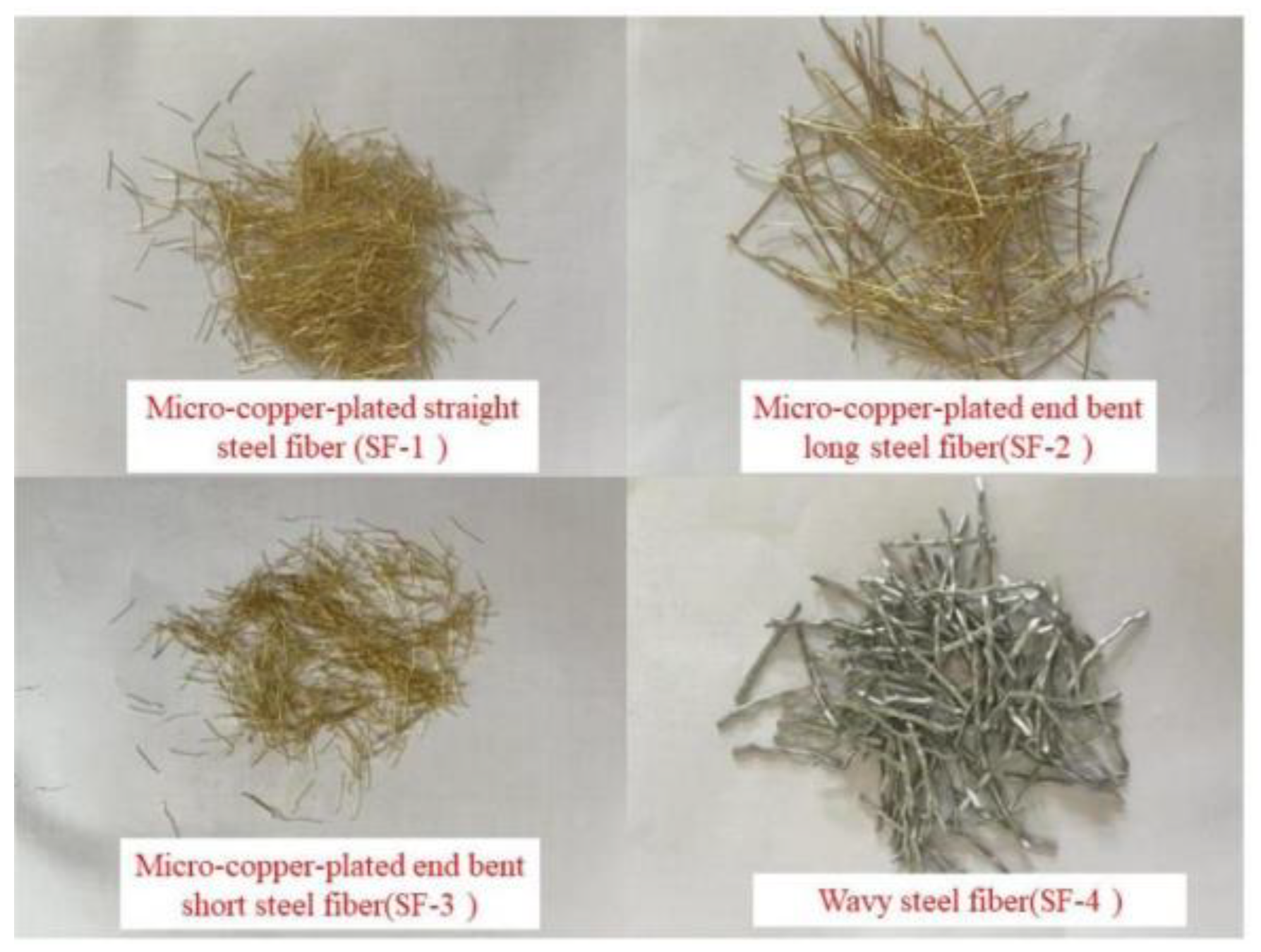
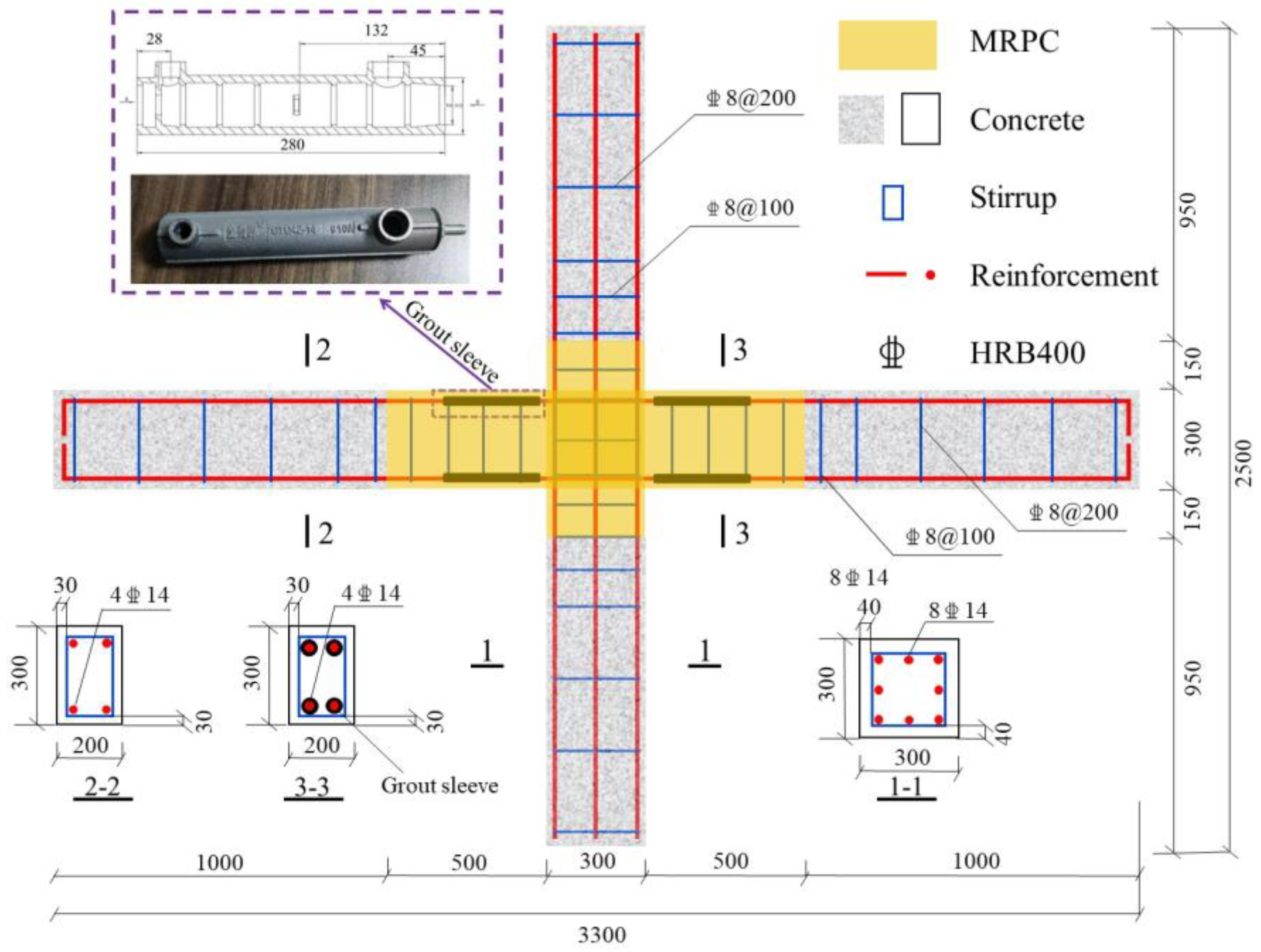
This experiment’s research object was the frame structure’s beam–column middle connections. According to the Chinese “Code for design of concrete structures (GB 50010-2010)” [26], five specimens with a 1:2 scale ratio were designed. They consisted of four assembled MRPC beam–column connections using different steel fiber types in critical cast-in-place regions and a monolithic concrete beam–column connection. Micro-copper-plated straight, end-bent, and wavy steel fibers were used as MRPC steel fibers, as shown in Figure 1. Table 1 shows these steel fibers’ characteristics, and Table 2 shows the number of each of the five specimens. The axial load ratio was 0.3. The sectional dimensions of beams and columns were 200 mm × 300 mm and 300 mm × 300 mm, respectively. The use of grout sleeves to connect the longitudinal reinforcements is widely used in engineering. In the previous investigation of the research group [27], the stiffness and strength of the structure can be stably improved. Therefore, this study uses grout sleeves to connect reinforcements. According to the Chinese code, “The grouting sleeve for rebars splicing (JG/T 398-2019)” [28], the connection area at one end of the grout sleeve is greater than 8 d (steel diameter). Therefore, the length of the grout sleeve selected is selected as 280 mm. Figure 2 shows the MRPC’s assembled connections’ dimensions and reinforcement configurations.
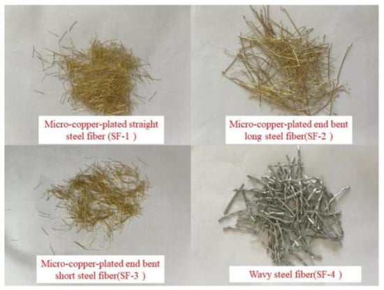
Figure 1.
Steel fiber.

Table 1.
Characteristics of fibers.
Table 2.
The conditions of the five specimens.

Figure 2.
Dimension and details of specimens.
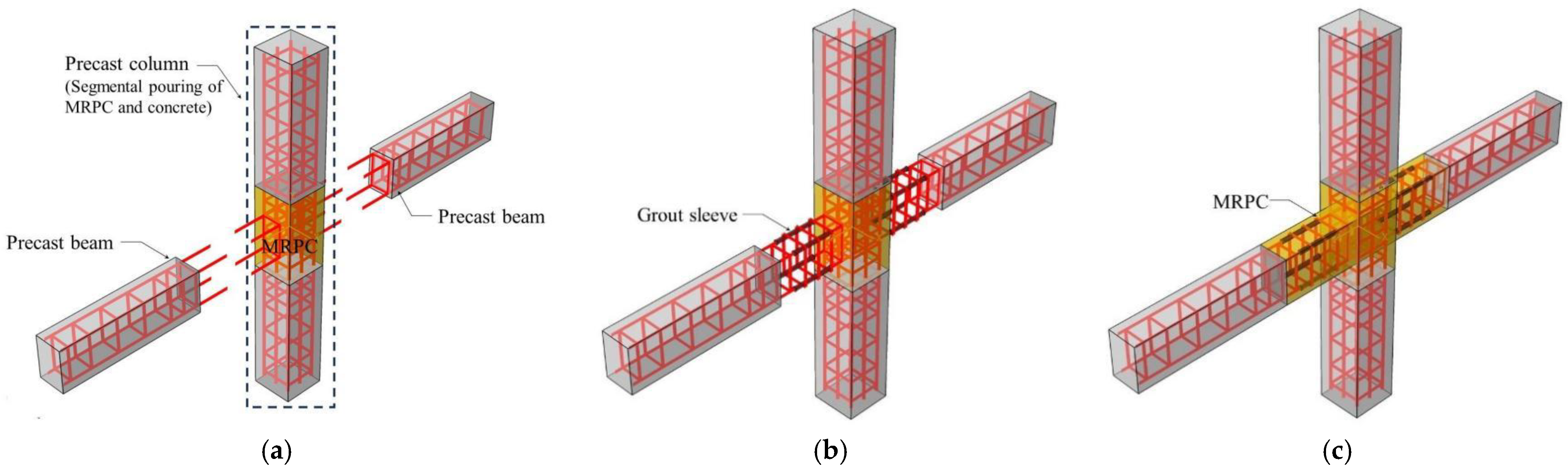
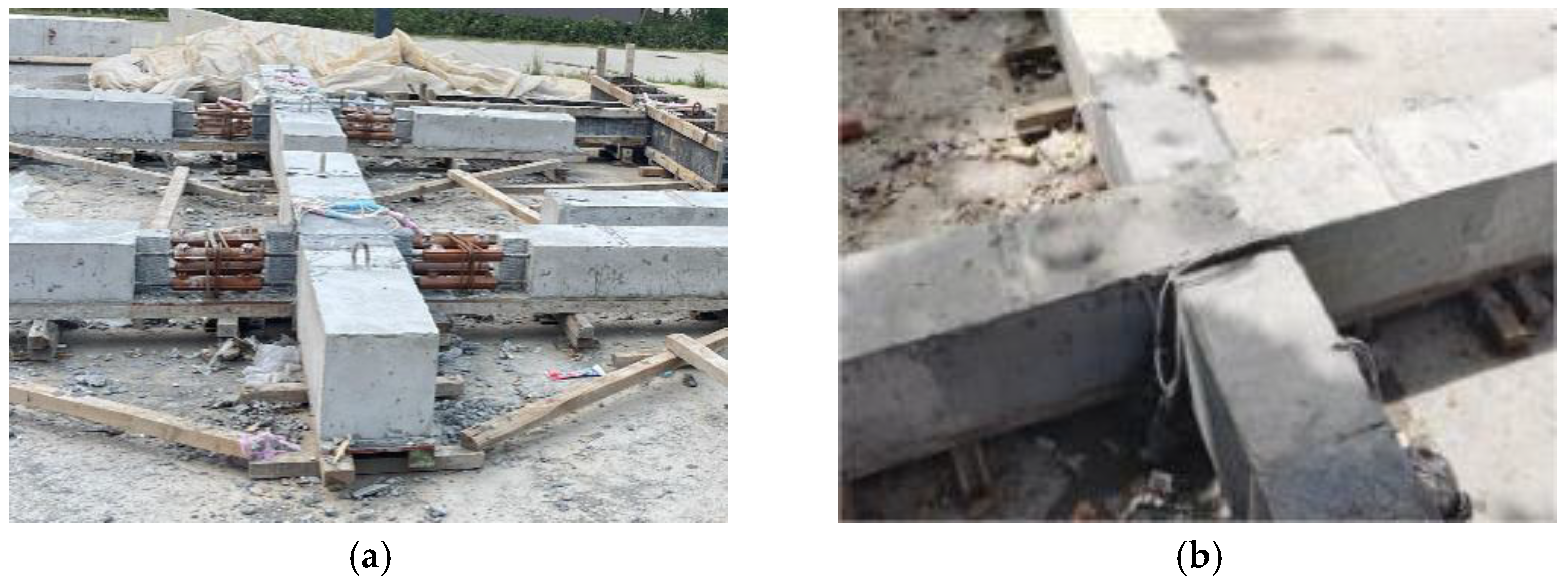
Considering the design requirements for strong columns and weak beams, precast columns required segmented and integrated MRPC and C35 concrete pouring, while MRPC at the beam ends was poured after connections assembly and maintenance were completed [29]. The MRPC assembled connection’s production process included three main steps: production of the precast beam and column, assembling and sleeve grouting, and MRPC casting at the beam end, as shown in Figure 3. When tying reinforcements, using the limit plate ensured accurate spacing between each steel bar.

Figure 3.
Construction sequence of an assembled beam–column connection. (a) Production of precast components. (b) Assembling and sleeve grouting. (c) Casting of MRPC in situ.
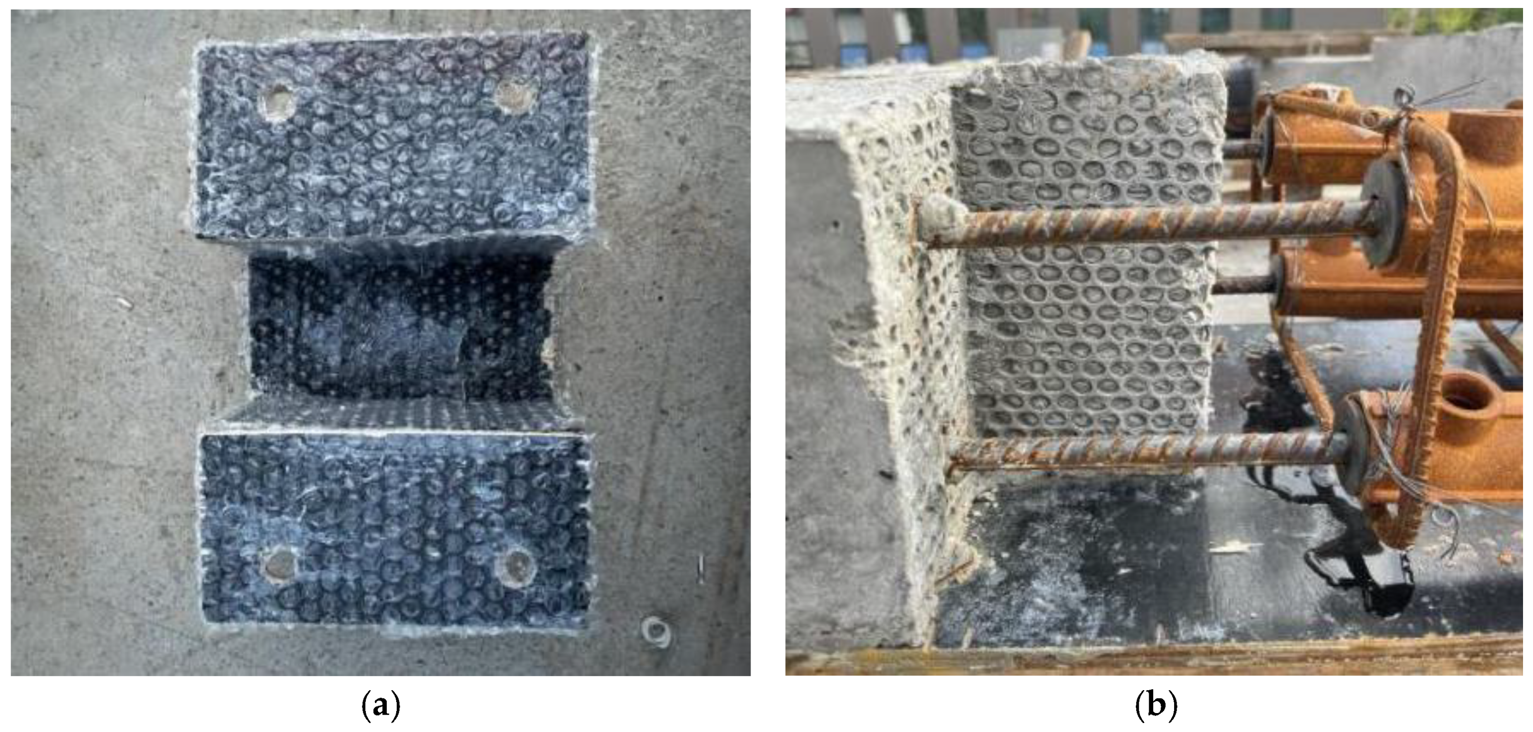
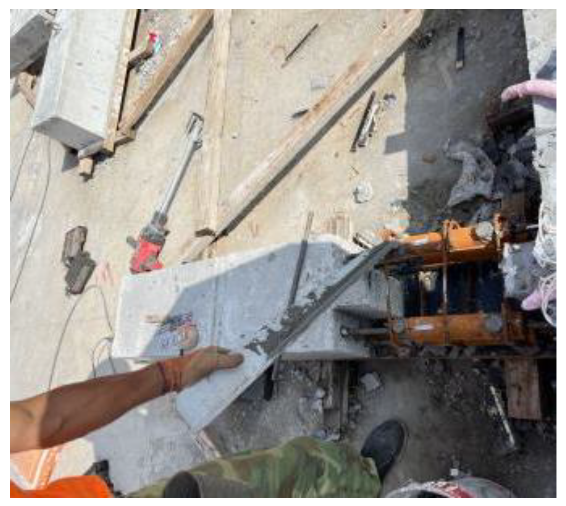
The interface between the precast beam and the MRPC was the structure’s weak region. To increase interface bonding, the assembled beams’ ends were irregularly shaped, and an air bubble film was pasted on the formwork to increase its roughness [30], as shown in Figure 4. Assembled beam–column connections using MRPC in critical cast-in-place regions are shown in Figure 5.
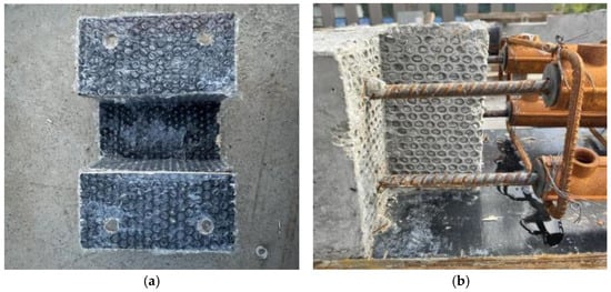
Figure 4.
Design of interface between MRPC and concrete. (a) Formwork for concrete. (b) Interface between MRPC and concrete.
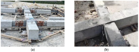
Figure 5.
Assembled beam–column connections. (a) Assembling components. (b) Secondary pouring of MRPC.
2.2. Material Properties
2.2.1. MRPC
Adding fiber to concrete has certain limitations and can only improve a single concrete characteristic. Different fibers can be added to improve concrete’s performance. The random distribution of steel fibers in concrete can effectively prevent internal cracks from expanding. Polypropylene (PP) fibers can dissipate energy through deformation and extraction, which further improves concrete’s toughness [31]. The hybrid effect between two fibers improves MRPC’s seismic performance [21].
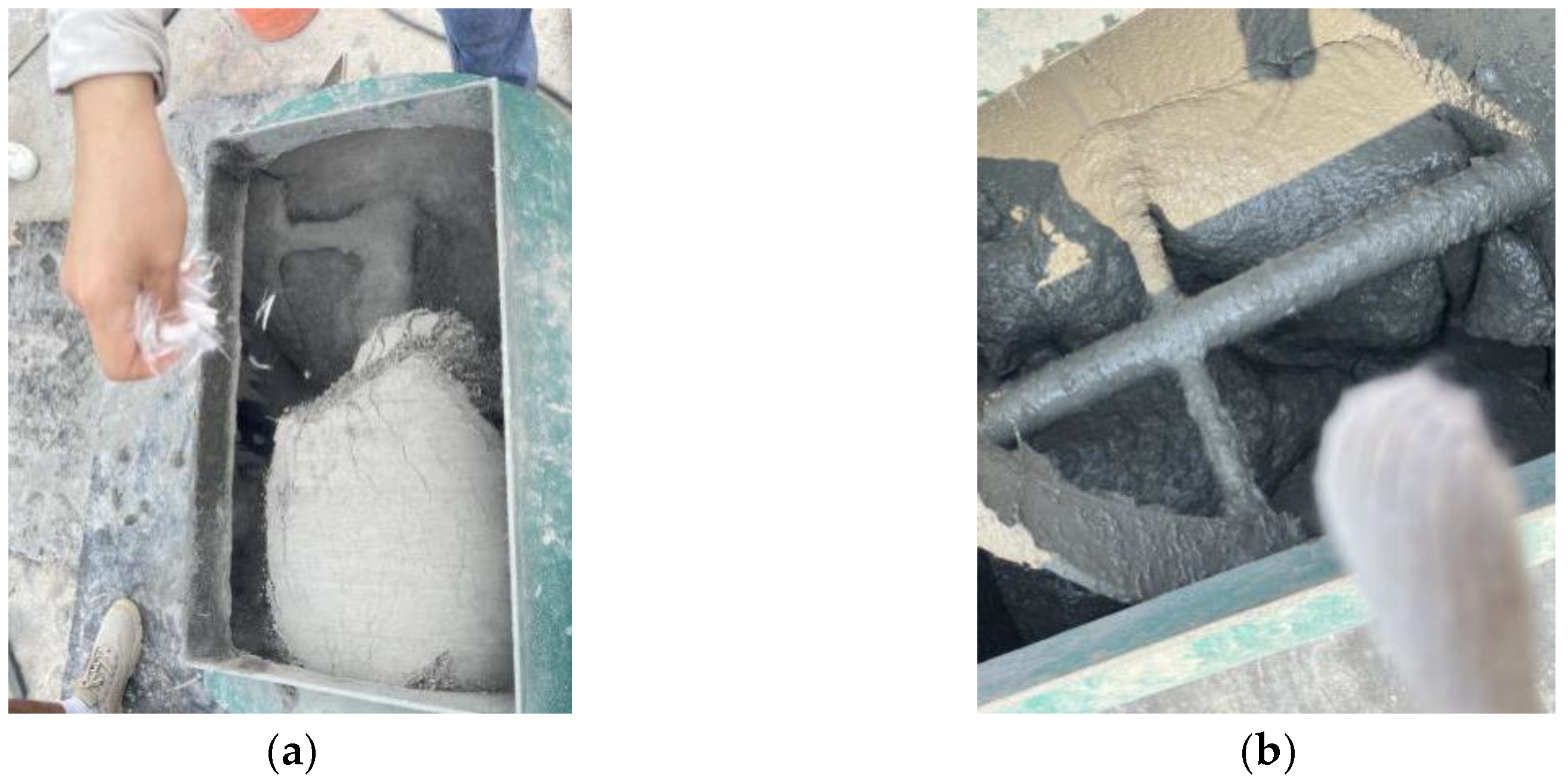
Notably, during MRPC manufacturing, cementitious materials are first poured into a slightly wet mixer in sequence and then mixed dry for 1.5 min. Next, small quantities of steel fibers, water-reducing agents, and PP fibers are poured into the mixer multiple times and further mixed for 2 min. Finally, water is gradually poured into the mixer, and stirring continues for 2 min until all materials are thoroughly mixed and exhibit good fluidity, as shown in Figure 6.
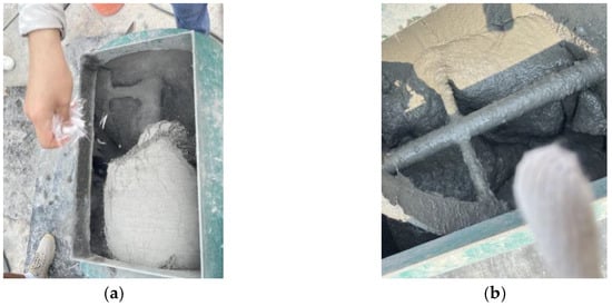
Figure 6.
The manufacturing process of MRPC. (a) Dry material mixing. (b) Wet material mixing.
If the fiber volume is too large, fibers will intertwine and interlace with each other, resulting in a negative hybrid effect and increasing the MRPC materials’ cost. The water–binder ratio and superplasticizer affect MRPC’s fluidity and strength. MRPC materials need to have good workability and be able to meet fluidity and bonding requirements. In addition, the strength difference between the MRPC and the concrete should not be too large, considering the workability and strength requirements of MRPC materials comprehensively. In the previous investigation of the research group [21], the selected steel fiber content was 1.5%, and the optimal mix ratio of MRPC is shown in Table 3.
Table 3.
The optimal mix ratio of MRPC.
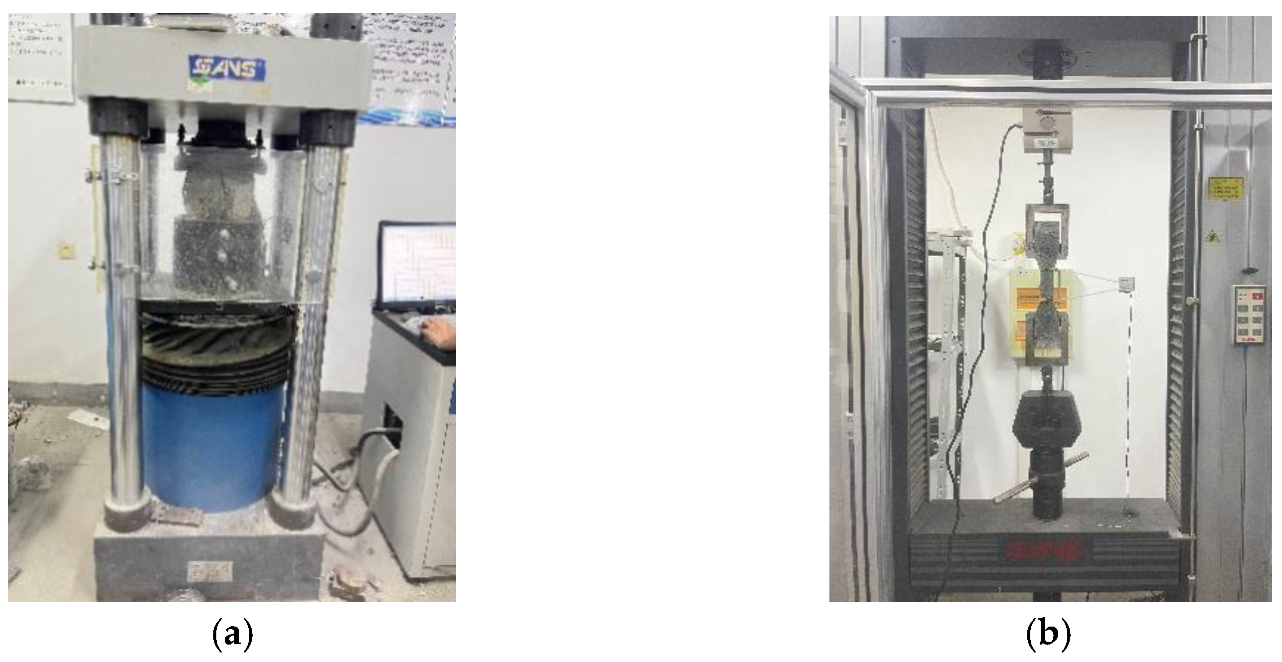
The MRPC mix ratio was determined using mechanical performance tests. MRPC compressive test specimens were 100 mm × 100 mm × 100 mm cubes, and tensile test specimens were 100 mm × 15 mm and dog-bone-shaped. C35 compressive test specimens were 150 mm × 150 mm × 150 mm cubes. The mix ratio of C35 is shown in Table 4. Testing instruments are shown in Figure 7. To accurately obtain the MRPC’s strength in beam–column connections, the same batch of concrete mechanical performance tests were conducted during the pouring of beam–column connections, as shown in Table 5.
Table 4.
The mix ratio of C35.
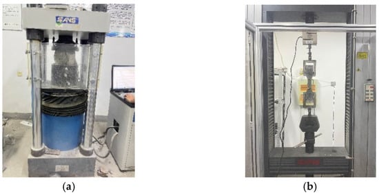
Figure 7.
Mechanical performance test. (a) Uniaxial compression test. (b) Uniaxial tensile test.
Table 5.
The material strength of the specimen.
2.2.2. Grouting Material
The sleeve was manufactured using nodular cast iron full grout, and the two ends were sealed with rubber plugs. When installing the sleeve, it was necessary to ensure that the grouting inlet and outlet were located upward so that the grouting material was smoothly injected into the sleeve, as shown in Figure 8. The grouting material’s compressive strength and fluidity tests are shown in Figure 9. The grouting material’s compressive strength at days 1, 3, and 28 was determined, as shown in Table 6. The grouting material’s fluidity results are shown in Table 7.

Figure 8.
Grouting material pouring.
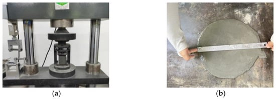
Figure 9.
Test of grouting material. (a) Compressive strengths. (b) Fluidity.
Table 6.
Compressive strengths of grouting material.
Table 7.
Test results of fluidity of grouting material.
2.3. Material Properties
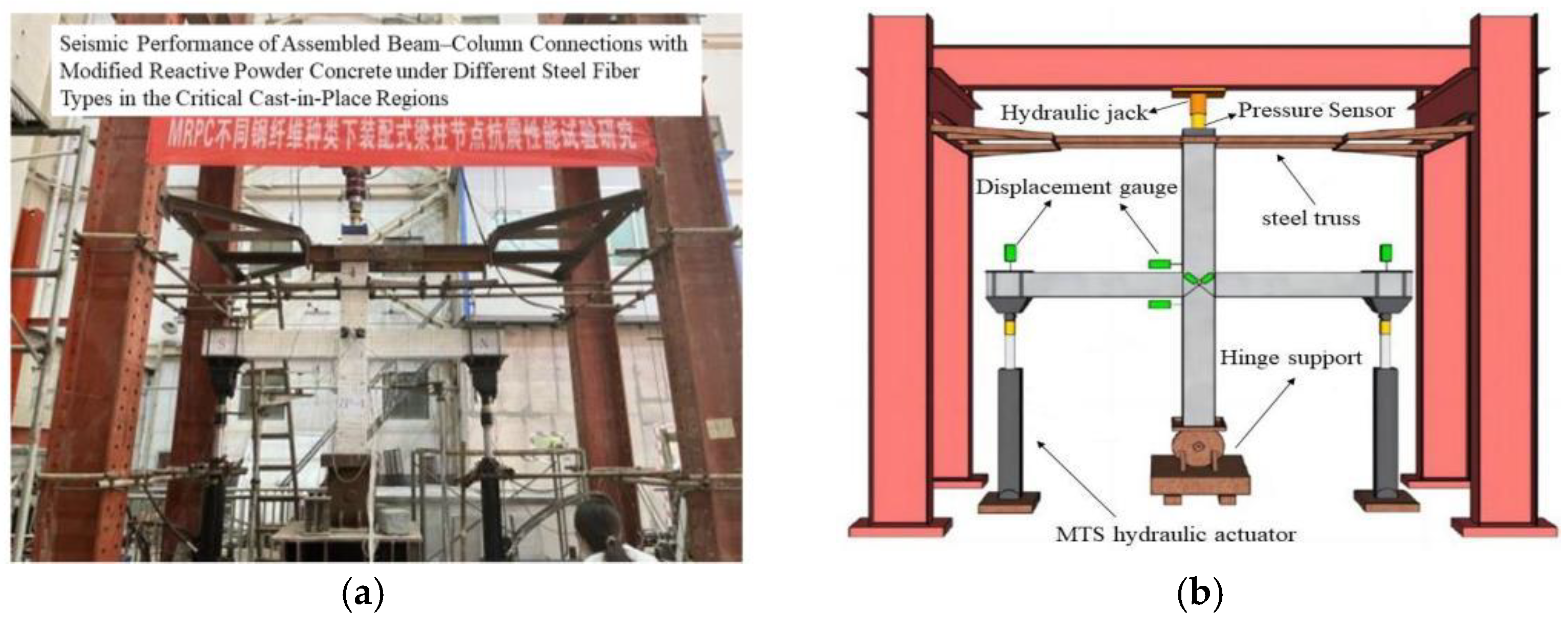
This test adopted the pseudo-static test loading method. The column’s two ends were fixed using a hinge support. Out-of-plane horizontal displacement was constrained by the transverse steel truss between the upper end of the column and the reaction frame. The bottom of the column was hinged to the steel support to simulate the actual force state. A 450 kN axial load was applied to the top of the column in stages using a hydraulic jack. This test used displacement-controlled loading, with two cycles per displacement step. A vertical antisymmetric cyclic load was applied to both ends of the beam using two MTS 250 kN hydraulic actuators. The test loading device is shown in Figure 10.

Figure 10.
Loading apparatus. (a) Test setup at the scene. (b) Schematic diagram of test setup.
The test was divided into three stages: the elastic stage, yield stage, and failure stage. It was stipulated that pushing displacement was positive and pulling displacement was negative. The initial displacement step was set at 1.0 mm. When obvious initial cracks appeared in the specimen, the displacement step was adjusted to 4.0 mm. When the cyclic load increased less than the previous level, the displacement step was adjusted to 8.0 mm. Loading stopped when the capacity dropped below 85% of the peak load.
3. Test Results and Analysis
3.1. Failure Pattern
The failure modes of beam–column connections include flexural failure at the column end, flexural failure at the beam end, and shear failure in critical areas. When the beam end becomes a weak part, the upper part of the beam end is strained by the reinforcements yield due to the negative bending moment, the lower part of the compressive concrete is crushed and falls off, and the through crack is formed at the beam end. Therefore, when there is an obvious plastic hinge at the end of the beam, the connection is broken by bending.
In addition, the characteristic of column-end bending failure is the formation of plastic hinges at the column end, and the shear failure in the critical region is manifested as diagonal cracks appearing in the concrete in the critical region.
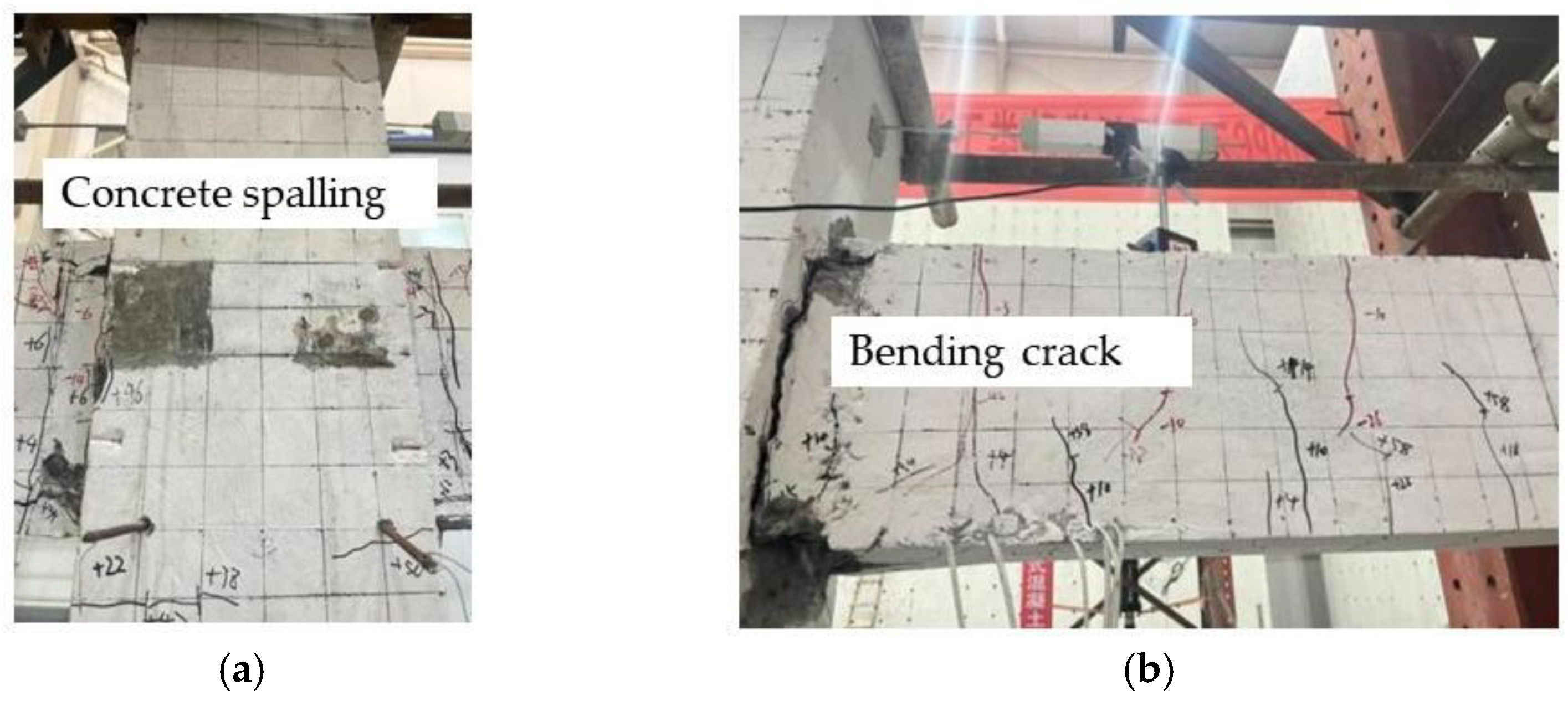
Specimen XJ exhibited a beam-end bending failure pattern, as shown in Figure 11a. The poor tensile performance of concrete leads to rapid cracking of the tensile zone of the beam under external forces, transferring stress to the steel bars. Therefore, the first vertical crack appeared in the beam’s tension area, and then oblique cracks began to appear in the area closer to beam–column interfaces. When loading entered the late stage, macroscopic cracks appeared at the end of the beam. Finally, the beam–column connections’ concrete fell off, the reinforcement yielded, and the specimens were severely damaged. The integral RC beam–column connections had significant brittleness characteristics and poor seismic performance. Although the failure pattern of assembled specimens was also beam-end bending, MRPC’s tensile strength was higher, and the steel fibers could better inhibit crack occurrence and development; the number and width of cracks were significantly reduced. In addition, there was no concrete spalling off the MRPC surface, as shown in Figure 11.
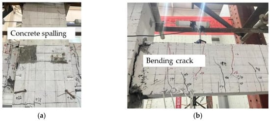
Figure 11.
Failure pattern of XJ. (a) Critical area cracking. (b) Beam end cracking.
The bond between straight steel fibers and the cement matrix was poor; it was easily pulled out, losing the bridging effect and resulting in more comprehensive crack development. Therefore, the SFZP-1 beam had more cracks than the other assembled specimens, as shown in Figure 11a. Compared to straight fibers, the process of drawing end-bent fibers from the MRPC matrix was more complex. Figure 12b,c illustrates that the bending portion at the steel fiber’s end was forcibly deformed during the drawing process, providing some mechanical force and thereby enhancing the anchoring force between the steel fiber and the MRPC matrix. Because end-bent long fibers have better anchoring depth, they could effectively suppress the development of macroscopic cracks during the later loading stage and were not quickly pulled out. SFZP-3 had the lowest number of connection cracks; compared to long fibers, SFZP-3 had shorter fibers, and its disorderly distribution system was more compact, which had a significant inhibitory effect on microcracks’ generation and development. Figure 12d illustrates wavy steel fibers strengthening the bond with the matrix because of their continuous irregular shapes, which reduced the number of cracks; however, their effect was not as good as that of end-bent steel fibers because the wavy shape could not provide more mechanical bite force to MRPC.
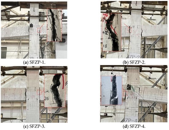
Figure 12.
Failure pattern of assembled beam–column connections. (a) SFZP-1. (b) SFZP-2. (c) SFZP-3. (d) SFZP-4.
3.2. Load–Displacement Hysteretic Loops
The load–displacement hysteretic loops of MRPC assembled connections and the monolithic connection were similar. In the elastic stage, the specimens’ hysteresis loops were nearly straight, and their residual deformation after unloading was small. As the cracks continued to develop, the displacement growth rate was higher than the load growth rate, the hysteresis loops’ shape gradually tended to be full, and the residual deformation after unloading gradually increased. When the specimens entered the yield deformation stage, the reinforcements slipped to different degrees, and the hysteresis loops showed a certain degree of a pinching phenomenon. Finally, specimens formed a plastic hinge at the beam end. The main cracks alternately opened and closed under the cyclic load. The cracks continued to widen until the specimen failed.
Figure 13a shows that the area of XJ’s hysteresis loop was the smallest, and its seismic performance was the worst. Because there was an interface transition zone (ITZ) around the aggregate in ordinary concrete, which is a weak phase, cracks quickly penetrated the ITZ, reducing the concrete’s compressive area and quickly forming plastic hinges at the beam end. Compared with specimen XJ, the hysteresis curve area of assembled connections was larger and had better ductility; MRPC significantly improved the seismic performance of connections. However, the degree of pinching varied under different steel fibers. SFZP-1’s pinching was more significant, indicating that straight steel fibers had a lesser restraint effect on the cement matrix in the plastic stage. The steel fibers were quickly pulled out and exited the sample. The stress was transferred to the reinforcements, causing them to slip earlier. SFZP-4’s hysteresis loop was the fullest, indicating that the MRPC with wavy steel fibers was better able to coordinate deformation with reinforcements and consume energy; because wavy steel fibers have a flat shape, they had a larger contact area with the substrate. In addition, the continuous and irregular shape was similar to ribbed steel bars, and the friction force between the steel fibers and the matrix was greater. Under repeated loads, the sliding of wavy steel fibers could consume more energy.
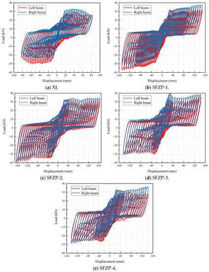
Figure 13.
Load–displacement hysteretic loops. (a) XJ. (b) SFZP-1. (c) SFZP-2. (d) SFZP-3. (e) SFZP-4.
The slippage of the assembled MRPC joints can be improved by using copper-coated hook steel fiber, and the energy dissipation capacity of the assembled joints can be improved by using wavy steel fiber.
3.3. Skeleton Curves
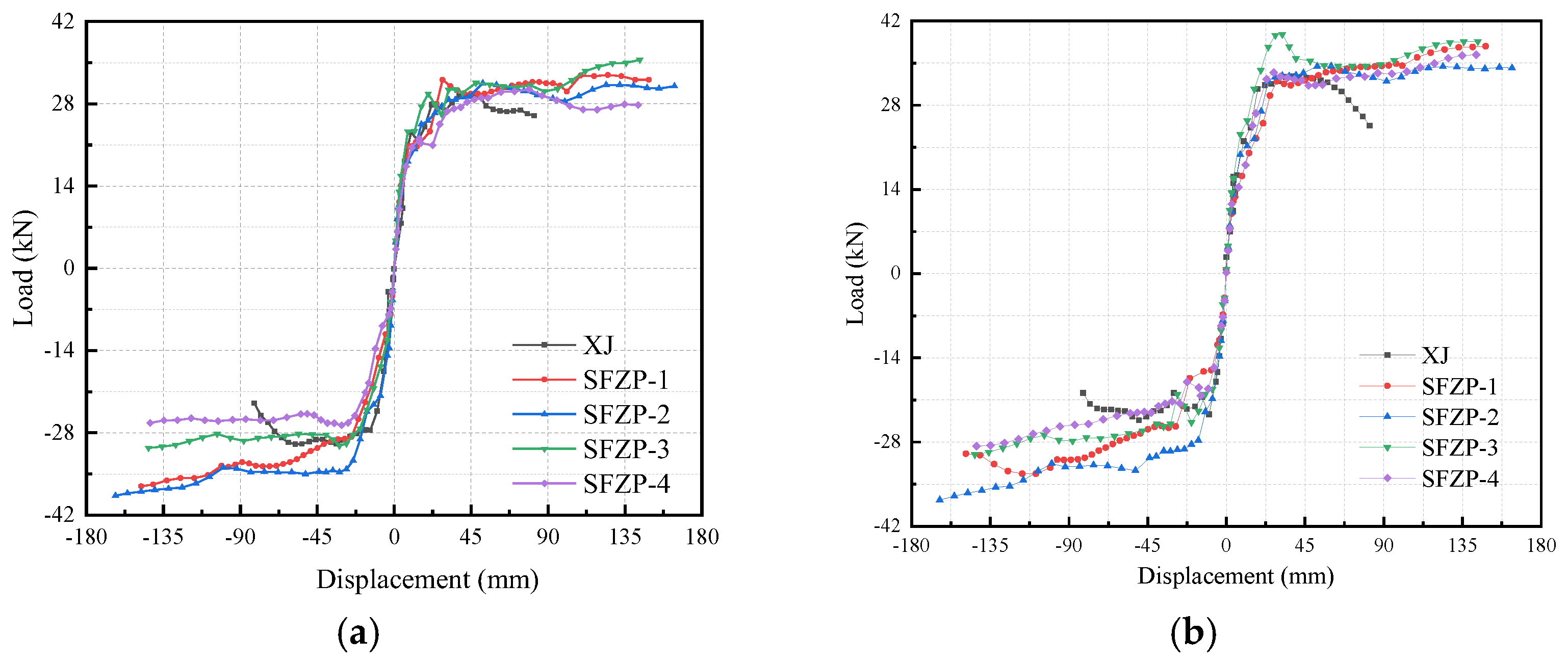
The skeleton curve is the peak cyclic loading point at all levels and reflects different stages of structures’ force and deformation processes. XJ’s crack development was rapid and was manifested by a rapid decline in the curve after the peak; the concrete’s mechanical performance seriously degraded, and the specimen presented a certain degree of brittleness. In MRPC, the interaction between the two fibers and the matrix inhibited damage accumulation. The specimens’ mechanical performances after the peak were relatively stable, showing a certain degree of ductility.
As Figure 14 shows, the load-carrying capacity of specimens using end-bent steel fibers was the best, probably because the end-bent shape was conducive to the formation of a uniform, dense, and highly connected hybrid system of fibers in the matrix. Overall, the load-carrying capacities of SFZP-3 and SFZP-2 were close, but SFZP-2’s mechanical performance was more stable after the peak load. SFZP-4’s load-carrying capacity was poor, indicating that the restraint effect of wavy steel fibers on the matrix was relatively small. Because SF-4 is not a micro steel fiber and has a large individual volume, it could not form an effective disorderly distribution system in the MRPC matrix. The ultimate displacement of SFZP-2 was larger than that of SFZP-3 due to the increase in fiber burial depth, which increased the bonding area between fibers and the MRPC matrix. End-bent long steel fiber could also bear part of the stress in the later loading stage, control crack development, and slow the height drop rate of the compression zone.
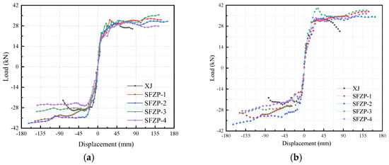
Figure 14.
Skeleton curves. (a) Left beam. (b) Right beam.
Applying MRPC to assembled beam–column connections without stirrups in the critical cast-in-place regions significantly improves the deformation capacity, bearing capacity, and ductility of the specimens. Therefore, MRPC can simplify the arrangement of steel bars in the core area. The copper-plated end hook steel fiber has the best effect on improving the bearing capacity of assembled beam–column connections.
3.4. The Load and Displacement of Characteristic Points
Beam–column connections require good ductility to ensure that the beam and column ends have sufficient deformation capacity. In this research, the ductility of the specimen was represented using the ductility coefficient (μ):
where Δu is ultimate displacement, and Δy is yield displacement. The yield point is determined by geometrical construction [33].
μ = Δu/Δy
Compared with the XJ, the assembled specimens’ ductility increased by 53%, 102%, 74%, and 42%, respectively, as shown in Table 8. The concrete structure’s brittleness was significantly improved due to MRPC’s better tensile strength and tensile hardening characteristics. As shown in Table 7, the ductility of assembled connections using end-bent steel fibers was higher. SFZP-2 entered the yield stage faster than SFZP-3, indicating that the hybrid effect formed by short and dense steel fibers better-delayed crack development during early loading. However, SFZP-2’s ultimate displacement was larger, indicating that the longer steel fiber delayed the duration of being pulled out during later loading, thereby inhibiting damage and enhancing the specimen’s ductility. Although SF-4’s fiber length was relatively long, SFZP-4’s ductility was the worst because micro steel fibers could form a disorderly distribution system in the matrix and work better together with PP fibers.
Table 8.
Loads and displacements of specimens at feature points.
The use of MRPC in the critical cast-in-place regions can improve the ductility of assembled beam–column connections and reduce the number of reinforcements in the critical regions, making construction easier.
3.5. Stiffness Degradation
The internal damage of concrete accumulates under cyclic loads, resulting in cracks. The slip between concrete and reinforcement increases gradually, and the stiffness of the specimen continues to decrease. The stiffness of the beam–column connections was represented using the secant stiffness (Ki):
where Fi+ and Fi− are the positive and negative peak load in the ith cycle, and Δi+ and Δi− are the positive and negative peak displacement in the ith cycle.
Ki = (Fi+ − Fi−)/(Δi+ − Δi−)
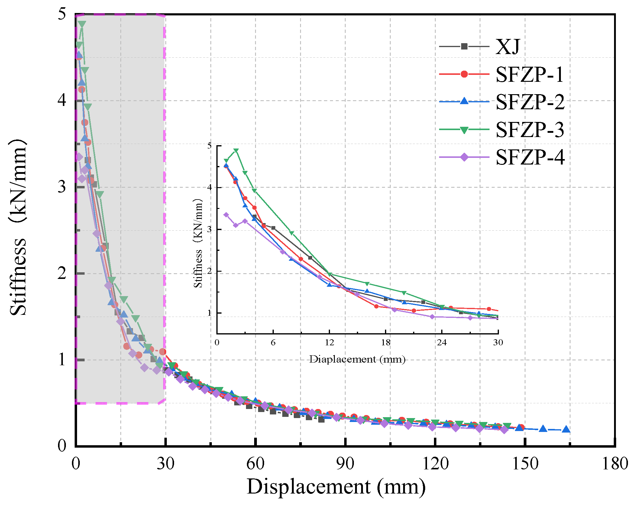
The five specimens’ stiffness degradation trends were similar, as shown in Figure 15. Due to the tightening of the actuator anchor rod and ground anchor bolt during the test process, specimens showed rapid increases in stiffness after the actuator loading surface was in close contact with the loading beam surface. Before specimens yielded, many cracks initiated and developed, and the stiffness decreased rapidly with the increase in displacement. After the specimens yielded, the stiffness degradation gradually slowed, there were fewer new cracks, and the specimens’ stiffness curves tended to be consistent.
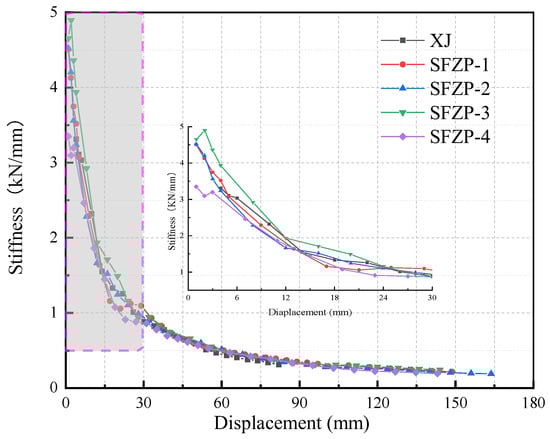
Figure 15.
Stiffness degradation.
Although the assembled specimens had weak regions due to secondary pouring, their initial stiffness was higher than that of XJ. This showed that the integrity of MRPC-assembled connections was excellent. The initial stiffness of SFZP-3 and SFZP-2 was relatively large, indicating that MRPC with end-bent steel fibers had relatively good resistance to deformation. SFZP-3’s initial stiffness was the largest because SF-3 was easier to stir, and its distribution of fibers was more uniform. In the later loading stage, because it was short, the steel fiber pulled out and withdrew from the sample, and the rate of stiffness decline obviously increased. The stiffness degradation of the MRPC with 30 mm end-bent steel fibers more effectively delayed crack development during the entire loading process and, to a certain extent, reduced damage accumulation. SFZP-4’s initial stiffness was only slightly higher than that of XJ. It might be that the interface bonding between MRPC and the assembled beam was relatively poor, which reduced the specimen’s stiffness.
The end-bent steel fibers will increase the initial stiffness of MRPC assembled connections, while the wavy steel fibers will slow down the stiffness degradation rate of MRPC specimens before yielding.
3.6. The Energy Dissipation Capacity
Under the earthquake, the structure will crack and yield, thereby consuming and absorbing the seismic energy, showing the characteristics of elastic-plastic restoring force. In this study, the energy dissipation capacity of the specimen was represented using cumulative energy dissipation (Ssum):
where n was the total number of cycles.
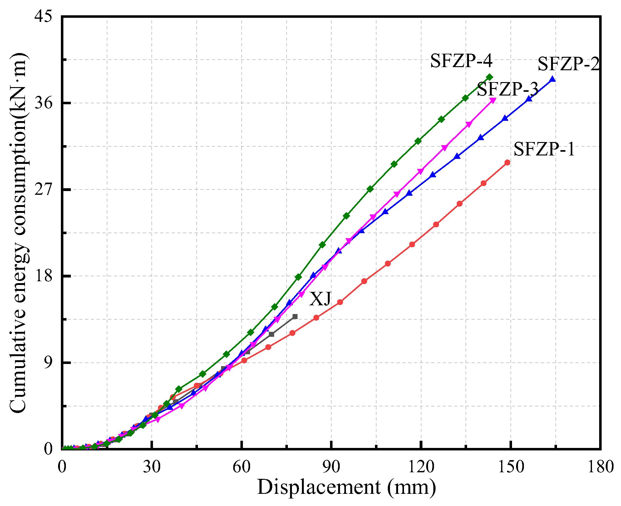
Figure 16 illustrates that there were almost no differences in the elastic stage. When the displacement was less than 80 mm, SFZP-1’s energy consumption was less than that of XJ, indicating that the linear steel fiber reduced the RPC matrix’s damage resistance. In the later loading stage, a plastic hinge area formed at the end of the beam and became the main energy dissipation area. SFZP-3’s energy dissipation capability was better than that of SFZP-2. Because the superposition effect of the PP fiber and steel fiber interface layer [34] strengthened the PP fiber interface (although SF-3 had a smaller volume and a larger number), the interface layer’s superposition effect was better. Due to wavy steel fibers’ continuous irregular shape and longer length, the sliding friction force between wavy steel fiber and the matrix was greater under cyclic loading, consuming more energy. SFZP-4 had the best energy dissipation capacity.
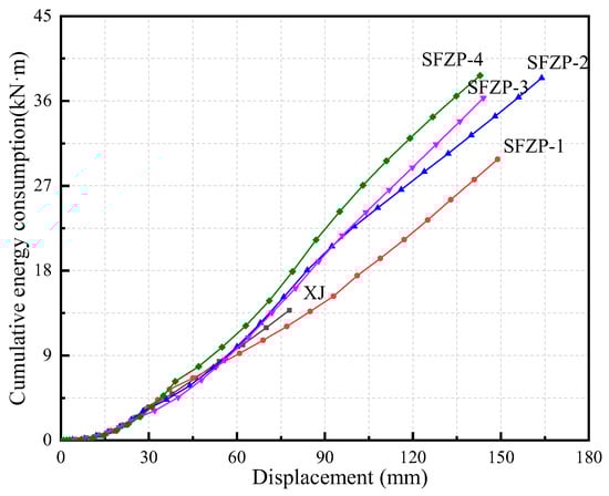
Figure 16.
Cumulative energy consumption.
Among the four types of steel fibers, the wavy and end-bent steel fibers have the best improvement effect on the energy consumption of assembled beam–column connections, while the straight steel fibers are slightly worse.
4. Prediction for Load Capacity
4.1. Crack Capacity
Cracks in beam–column connections have an impact on the seismic performance of structural strength, deformation, and durability [35]. Based on the crake capacity model of monolithic concrete connections, the crack capacity model of MRPC assembled beam–column connections is deduced.
The model makes the following assumptions:
- The MRPC is considered to be in the elastic stage before crack initiation;
- The shear effect of reinforcement is not considered, and it is considered that the shear stress is fully borne by MRPC before crack initiation;
- The beam axial force is neglected.
When the principal tensile stress of the oblique section of the connections reaches the initial crack strength of the MRPC, it will be in a critical state of cracking. The horizontal shear stress is obtained as follows:
where Vjcr is the shear force at the initial crack of the beam–column connections, and bj and hj are the effective width and height of the section of connections, respectively.
The beam–column connection is subjected to the vertical pressure transmitted by the column. The axial stress is obtained as follows:
where Nc is axial force, and bc and hc are the width and height of the section of the column, respectively.
The principal tensile stress of the connection is obtained as follows:
When the connection has not yet cracked, the principal tensile stress satisfies Equation (7). Considering that the connection is in a critical state of cracking, substituting Equations (4) and (5) into Equation (7), the shear force of the theoretical is obtained as follows:
where ftk is the initial cracking stress of the uniaxial tensile test of the MRPC.
The sheer force of the test can be calculated as follows [26]:
where Vjt is the cracking test value of the beam–column connections, Mb is the sum of the bending moments at the beam ends, Hc is the distance between the inflection points of the upper and lower columns, is the protective layer thickness, h0 is the effective height of the beam section, and hb is the height of the beam section.
The crack capacity is similar to the material strength of the specimen in Section 2.2. Short steel fibers can better suppress the generation and development of microcracks and significantly improve the initial cracking strength of connections. Because of the poor tensile capacity of MRPC-SF-4, the initial crack load of SFZP-4 is significantly lower than that of other specimens, as shown in Table 9. The end-bend steel fiber has the strongest restraining effect on the matrix. Considering that the reinforcement ratio of the connection is the same, it may be that the damage accumulated after the positive loading of the specimens leads to the low crake capacity under negative loading. The test value of connections (Vjt) is generally smaller than the theoretical value (Vjcr); thus, the Chinese code overestimated the shear contribution of MRPC. If η is defined as the safety factor, it is determined to be 0.80 according to the test data.
Table 9.
Test and theoretical value of crack capacity.
4.2. Shear Capacity
The stress of the beam–column connection is complex, which not only needs to bear the axial pressure of the column but also needs to bear the shear force and bending moment at the end of the beam and column. There are several theoretical models for the shear capacity of beam–column connections [26]. The shear capacity of beam–column connections can be calculated as follows:
where is the seismic adjustment coefficient of bearing capacity, taken as 0.85, and ηj is the constraint influence coefficient of the orthogonal beam, taken as 1.0. Asvj is the total area of the stirrups in the connections.
The shear capacity of SFZP-2 is the highest, as shown in Table 10, indicating that longer fibers are more conducive to controlling the development of cracks in the middle and late stages of loading. The test of shear capacity is generally smaller than the theoretical models, and Ψ is defined as the safety factor. Ψ is determined to be 0.85, according to the test data. The shear capacity of MRPC-assembled beam–column connections can be calculated as follows:
Table 10.
Test and theoretical value of shear capacity.
5. Conclusions
Experimental and analytical investigations of the seismic performance of four assembled beam–column connections using MRPC with different steel fiber types in critical cast-in-place regions and a monolithic concrete beam–column connection were conducted. The following main conclusions were drawn:
- The failure mode of the monolithic specimen and assembled specimens was beam-end bending failure. The monolithic specimen’s crack width was large, and concrete peeled off a large area of its main crack at the beam end. However, there was no concrete spalling on the MRPC’s surface, and the core area of connections was mostly fine inclined cracks, which had good structural integrity. The application of MRPC in assembled beam–column connections significantly improved the structure’s damage tolerance capacity and avoided brittle failure;
- Straight steel fibers were easily pulled out and had the least inhibitory effect on cracks; SFZP-1’s comprehensive seismic performance was the worst. The seismic performances of specimens with end-bent steel fibers were better. Higher ductility was achieved using end-bent long fibers, which increased the monolithic concrete specimens’ ductility by 102%. Wavy steel fibers had the lowest initial stiffness and shear capacity but the highest energy dissipation capacity and the fullest hysteretic curve. Comprehensively considering various seismic performance indicators, using 30 mm end-bent steel fibers is recommended;
- End-bent short steel fibers had the greatest impact on crack-bearing capacity. End-bent long steel fibers had the greatest impact on shear capacity. The Chinese code overestimated MRPC’s shear contribution. Considering the influence coefficient, formulas for calculating the crack capacity and shear capacity of MRPC-assembled beam–column connections were established.
Author Contributions
Conceptualization, X.W. and D.H.; funding acquisition, X.W.; investigation, X.W., D.H., and Q.G.; methodology, X.W. and D.H.; software, D.H. and Q.C.; supervision, D.H.; validation, Q.G.; visualization, D.H.; writing—original draft, X.W.; writing—review and editing, D.H. All authors have read and agreed to the published version of the manuscript.
Funding
This research was funded by the Natural Science Foundation of Shandong Province under Grant ZR2022ME164, Major Scientific & Technological Innovation Projects of Shandong Province under Grant 2021CXGC011204, and Engineering Research Institute of Appraisal and Strengthening of Shandong Jianzhu University CO., LTD under Grant, H19230Z.
Institutional Review Board Statement
Not applicable.
Informed Consent Statement
Not applicable.
Data Availability Statement
Not applicable.
Acknowledgments
The authors thank the anonymous reviewers and editors for their constructive comments on this manuscript.
Conflicts of Interest
The authors declare no conflict of interest.
References
- Li, W.; Lin, X.S.; Bao, D.W.; Xie, Y.M. A review of formwork systems for modern concrete construction. Structures 2022, 38, 52–63. [Google Scholar] [CrossRef]
- He, H.F.; Li, Z.P. Effect Mechanism of Connection Joints in Fabricated Station Structures. Appl. Sci. 2021, 11, 11927. [Google Scholar] [CrossRef]
- Jia, S.Z.; Cao, W.L.; Liu, Z.B.; Ding, W.; Su, Y.A. Experimental Study on a Prefabricated Lightweight Concrete-Filled Steel Tubular Framework Composite Slab Structure Subjected to Reversed Cyclic Loading. Appl. Sci. 2019, 9, 1264. [Google Scholar] [CrossRef]
- Xia, K.; Hu, X.; Xue, W.C. Experimental studies on in-plane connections of composite beam-assembled concrete shear wall under reversed cyclic loading. Structures 2021, 34, 1961–1972. [Google Scholar] [CrossRef]
- Deng, M.K.; Ma, F.D.; Song, S.F.; Lu, H.; Sun, H. Seismic performance of interior assembled concrete beam–column connections with highly ductile fiber-reinforced concrete in the critical cast-in-place regions. Eng. Struct. 2020, 210, 110360. [Google Scholar] [CrossRef]
- Gul, M.A.A.; Khan, S.W.; Ishaq, M.; Khan, F.A.; Shahzada, K.; Gul, M.S.A. Structural behaviour of RC-ECC beam–column connections under quasi-static loading. Mater. Today Commun. 2023, 35, 105763. [Google Scholar] [CrossRef]
- Li, J.; Xu, Y.; Tian, Z.F.; Ma, J.; Jing, P.; Song, Z. Study on leaching damage mechanism of calcium ions of reactive powder concrete (RPC) under ion corrosion. Constr. Build. Mater. 2020, 269, 121303. [Google Scholar] [CrossRef]
- Al-Tikrite, A.; Hadi, M.N.S. Axial-flexural interaction diagram of RPC columns reinforced with steel fibres. Structures 2019, 19, 499–506. [Google Scholar] [CrossRef]
- Shaheen, E.; Shrive, N.G. Optimization of Mechanical Properties and Durability of Reactive Powder Concrete. ACI Mater. J. 2006, 103, 444–451. [Google Scholar]
- Wen, B.; Huang, D.; Zhang, L.; Song, Q.Y.; Gao, G.Y.; Huo, D.W. Study on mechanical properties and size effect of coal gangue concrete at mesoscale. Constr. Build. Mater. 2022, 360, 129551. [Google Scholar] [CrossRef]
- Salahuddin, H.; Qureshi, L.A.; Nawaz, A.; Raza, S.S. Effect of recycled fine aggregates on performance of Reactive Powder Concrete. Constr. Build. Mater. 2020, 243, 118223. [Google Scholar] [CrossRef]
- Heidari, A.; Shourabi, F.N. Mechanical properties of ultra-high performance concrete based on reactive powder concrete: Effect of sand-to-cement ratio, adding glass fiber and calcium carbonate. Constr. Build. Mater. 2023, 368, 130108. [Google Scholar] [CrossRef]
- Liu, M.; Dai, W.T.; Zhong, C.L.; Yang, X. Study on mechanical properties and microstructure of manufactured sand reactive powder concrete with different curing methods. Mater. Lett. 2023, 335, 133818. [Google Scholar] [CrossRef]
- İpek, M.; Yilmaz, K.; Uysal, M. The effect of pre-setting pressure applied flexural strength and fracture toughness of reactive powder concrete during the setting phase. Constr. Build. Mater. 2012, 26, 459–465. [Google Scholar] [CrossRef]
- Vijay, A.; Senthilselvan, S. Mechanical properties of reactive powder concrete under distinct curing environment. Mater. Sci. Eng. 2021, 1101, 012018. [Google Scholar] [CrossRef]
- Wang, X.; Huang, D.; Gao, Y.C.; Li, L.Z. Experimental study on seismic performance of low strength shear walls strengthened with modified reactive powder concrete. Structures 2023, 57, 105094. [Google Scholar] [CrossRef]
- Ren, P.F.; Hou, X.M.; Cui, Z.Q.; Xie, H.; Abid, M. Fire resistance evaluation and minimum reinforcement ratio for hybrid fibre-reinforced RPC beams under fire exposure. J. Build. Eng. 2021, 44, 103216. [Google Scholar] [CrossRef]
- Alyaa, A.A.; Mazin, A.; Hussein, H.; Bassam, T. Investigating the behaviour of hybrid fibre-reinforced reactive powder concrete beams after exposure to elevated temperatures. J. Mater. Res. Technol. 2020, 9, 1966–1977. [Google Scholar] [CrossRef]
- Shan, B.; Liu, G.; Li, T.Y.; Liu, Z.; Xiao, Y. Experimental research on seismic behavior of concrete-filled reactive powder concrete tubular columns. Eng. Struct. 2021, 233, 111921. [Google Scholar] [CrossRef]
- Hadi, M.N.S.; Al-Tikrite, A. Behaviour of fibre-reinforced RPC columns under different loading conditions. Constr. Build. Mater. 2017, 156, 293–306. [Google Scholar] [CrossRef]
- Liu, G.A.; Wang, X.; Yang, Z. Experimental Study on Seismic Performance of Confined Masonry Walls With Window Openings Strengthened by Using Hybrid-Fiber Modified Reactive Powder Concrete. Front. Mater. 2022, 9, 832579. [Google Scholar] [CrossRef]
- Ma, F.D.; Deng, M.K.; Ma, Y.R.; Lu, H.; Yang, Y.; Sun, H. Experimental study on interior assembled concrete beam–column connections with lap-spliced steel bars in field-cast RPC. Eng. Struct. 2021, 228, 111481. [Google Scholar] [CrossRef]
- Yu, J.B.; Xu, Z.Q.; Xia, Y.F.; Guo, Z.X. Seismic behavior of reactive powder concrete (RPC) interior beam–to-column joints under reversed cyclic loading. Case Stud. Constr. Mater. 2023, 18, e01792. [Google Scholar] [CrossRef]
- Wang, D.H.; Zheng, W.Z.; Ju, Z.Y.; Wei, C.M. Experimental study on seismic behavior of interior steel fiber reinforced RPC beam–column joints. J. Build. Struct. 2019, 40, 161–171. [Google Scholar]
- Ju, Z.Y.; Li, C.Y.; Wang, D.H. Nonlinear Finite Element Analysis for Seismic Performance of Reactive Powder Concrete (RPC) Beam–column Joints. J. Basic Sci. Eng. 2015, 23, 932–941. [Google Scholar]
- GB 50010-2010; Code for Design of Concrete Structures. China Architecture & Building Press: Beijing, China, 2010.
- Yan, Q.; Chen, T.; Xie, Z. Seismic experimental study on a assembled concrete beam–column connection with grout sleeves. Eng. Struct. 2018, 155, 330–344. [Google Scholar] [CrossRef]
- JG/T 398-2019; The Grouting Sleeve for Rebars Splicing. China Architecture & Building Press: Beijing, China, 2019.
- Chen, K.Z. Seismic Behavior of Joints Assembled Using Prefabricated Beams and Columns with High Ductility Recycled Powder Concrete; Shandong Jianzhu University: Jinan, China, 2022; pp. 27–36. [Google Scholar]
- Li, X.L.; Li, Y.; Yan, M.; Meng, W.; Lu, X.; Chen, K.; Bao, Y. Cyclic behavior of joints assembled using prefabricated beams and columns with Engineered Cementitious Composite (ECC). Eng. Struct. 2021, 247, 113115. [Google Scholar] [CrossRef]
- Yao, Z.X.; Zhou, J.; Zhou, R.Z. Experimental Study on Fracture Properties of Reactive Powder Concrete (RPC). J. Build. Mater. 2006, 9, 654–659. [Google Scholar]
- JGJ 355-2015; Technical Specification for Grout Sleeve Splicing Rebars. China Architecture & Building Press: Beijing, China, 2015.
- Feng, P.; Qiang, H.L.; Ye, L.P. Discussion and definition on yield points of materials, members and structures. Eng. Mech. 2017, 34, 36–46. [Google Scholar]
- Zhu, R.R. Research on the Effects of Hybrid Fiber on Reactive Powder Concrete; Harbin Institute of Technology: Harbin, China, 2016. [Google Scholar]
- Xing, G.H.; Wu, T.; Liu, B.Q. Study on crack resistance of beam–colomn joints in reinforced concrete frame structures. Eng. Mech. 2011, 28, 163–169. [Google Scholar]


Disclaimer/Publisher’s Note: The statements, opinions and data contained in all publications are solely those of the individual author(s) and contributor(s) and not of MDPI and/or the editor(s). MDPI and/or the editor(s) disclaim responsibility for any injury to people or property resulting from any ideas, methods, instructions or products referred to in the content. |
© 2023 by the authors. Licensee MDPI, Basel, Switzerland. This article is an open access article distributed under the terms and conditions of the Creative Commons Attribution (CC BY) license (https://creativecommons.org/licenses/by/4.0/).