
Surface Engineering of Multi-Walled Carbon Nanotubes via Ion-Beam Doping: Pyridinic and Pyrrolic Nitrogen Defect Formation

 , ,
, ,  ,
,
Abstract
:1. Introduction
2. Materials and Methods
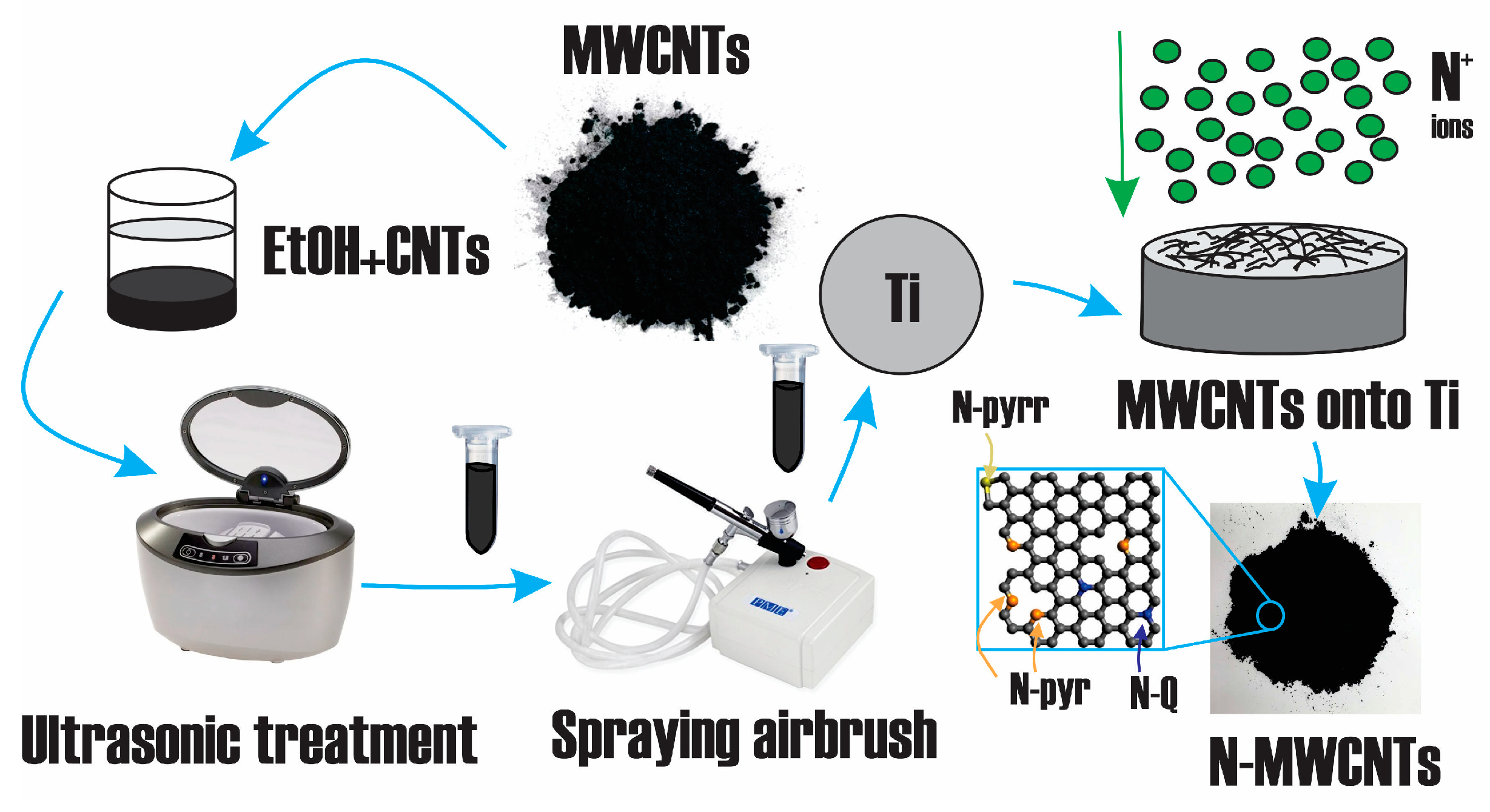
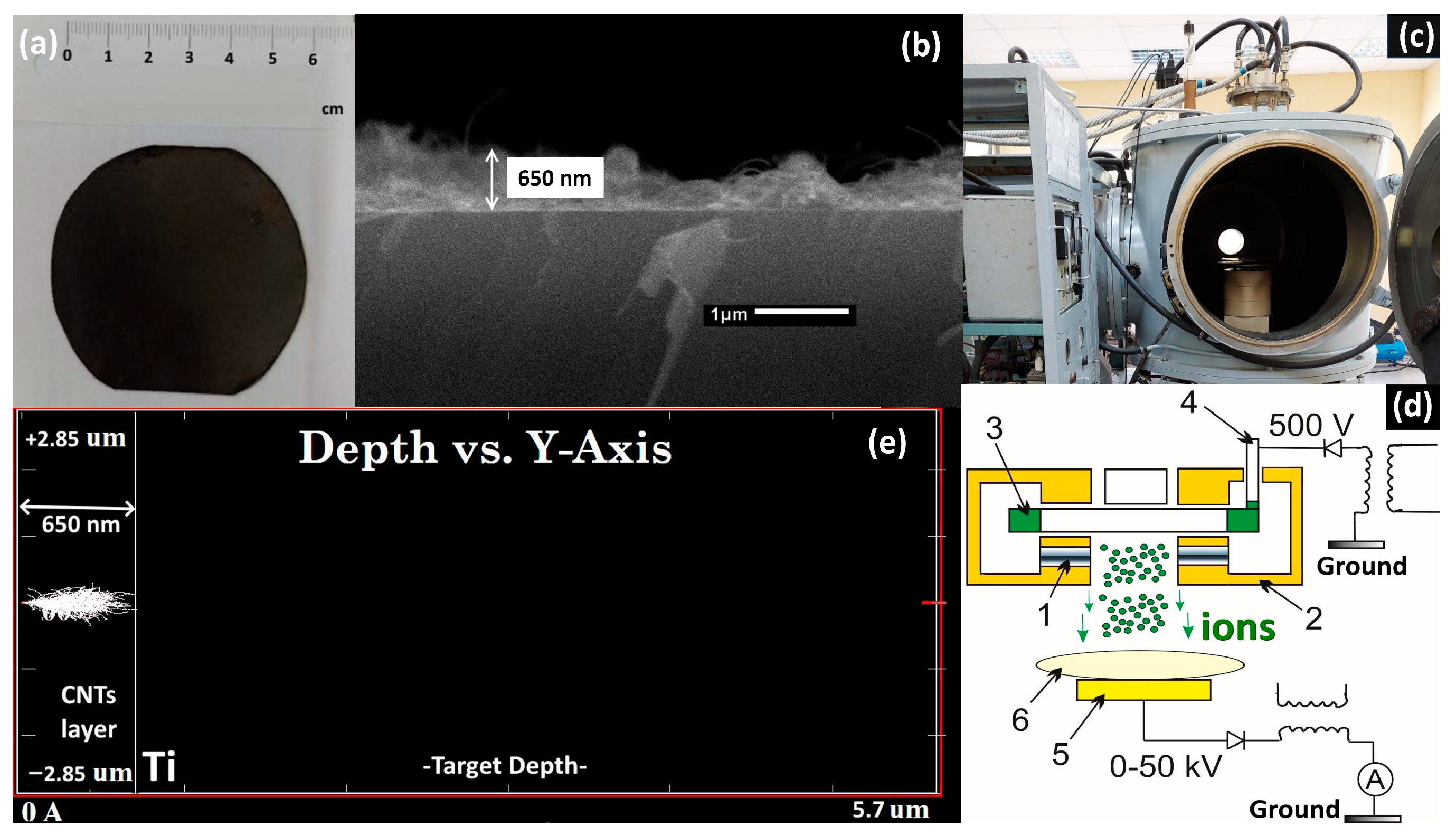
2.1. Sample Preparation
2.2. Sample Characterization
2.2.1. SEM
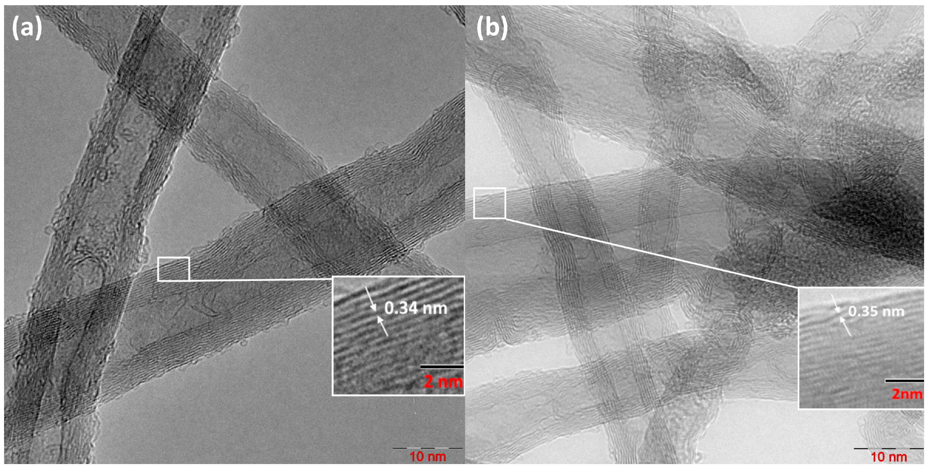
2.2.2. TEM
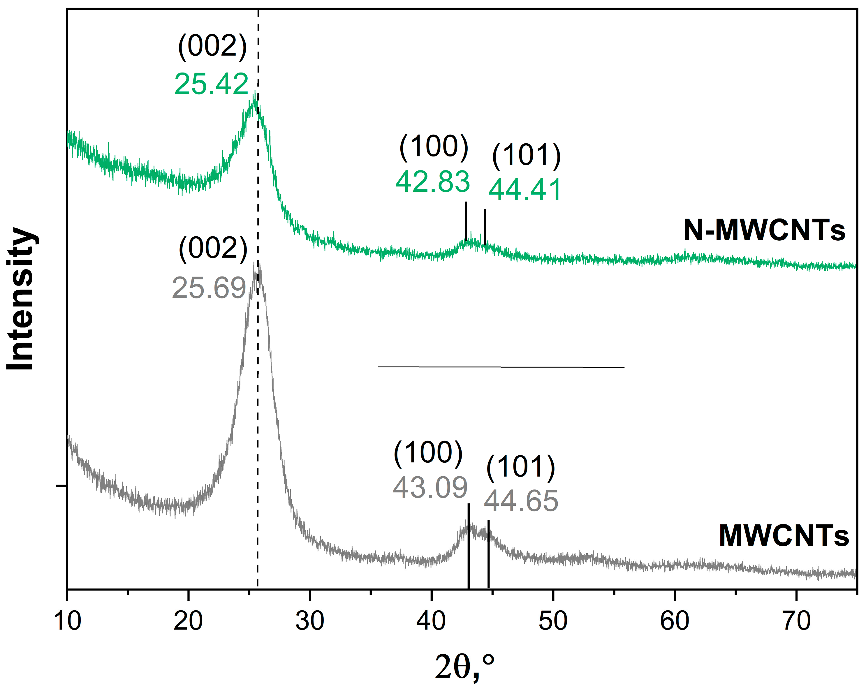
2.2.3. XRD
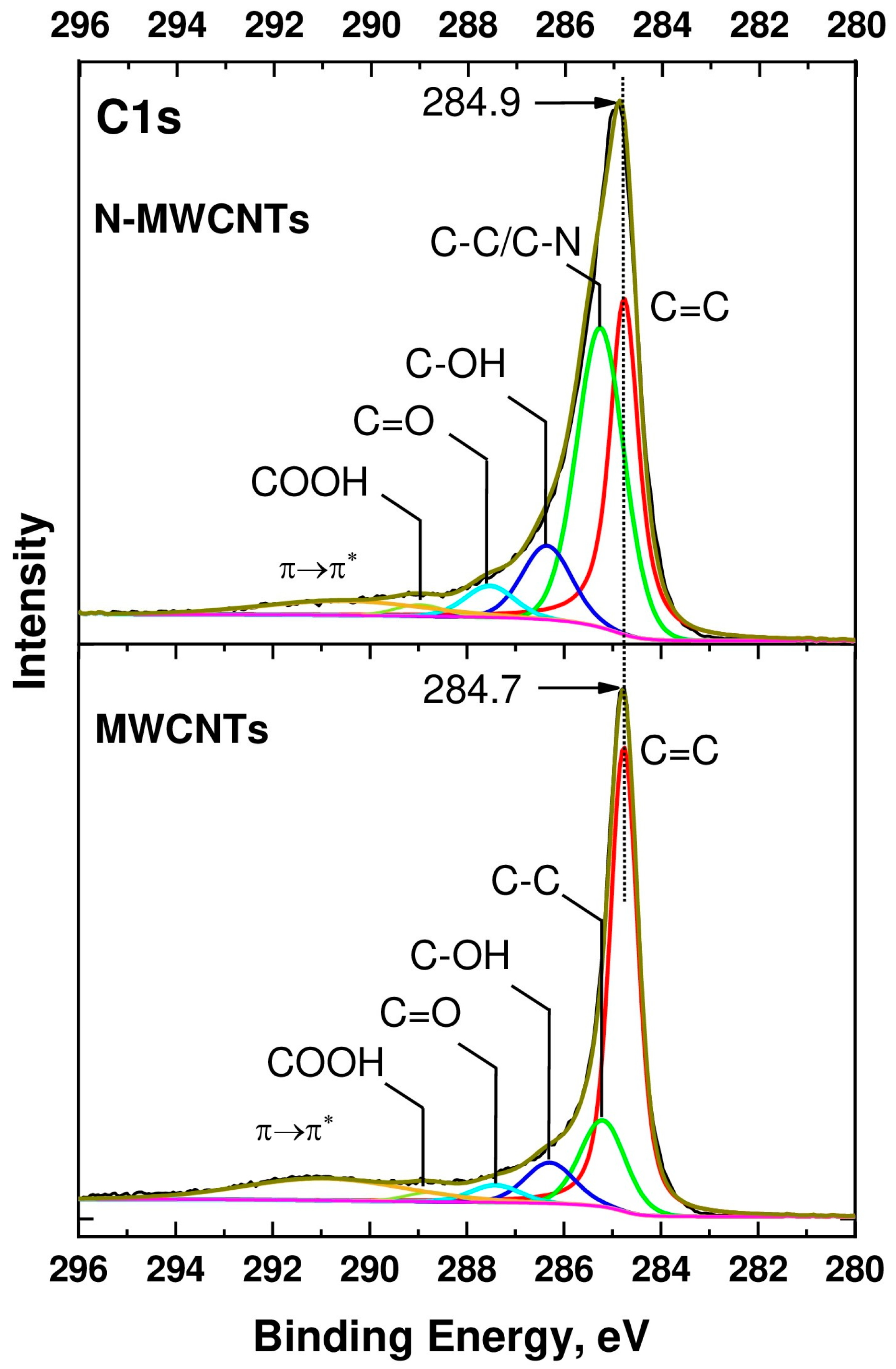
2.2.4. XPS
3. Results
4. Conclusions
Author Contributions
Funding
Institutional Review Board Statement
Informed Consent Statement
Data Availability Statement
Acknowledgments
Conflicts of Interest
References
- Wang, R.; Chen, D.; Wang, Q.; Ying, Y.; Gao, W.; Xie, L. Recent Advances in Applications of Carbon Nanotubes for Desalination: A Review. Nanomaterials 2020, 10, 1203. [Google Scholar] [CrossRef]
- Kumar Jagadeesan, A.; Thangavelu, K.; Dhananjeyan, V. Carbon Nanotubes: Synthesis, Properties and Applications. In 21st Century Surface Science—A Handbook; IntechOpen: London, UK, 2020. [Google Scholar] [CrossRef]
- Muchuweni, E.; Mombeshora, E.T.; Martincigh, B.S.; Nyamori, V.O. Recent Applications of Carbon Nanotubes in Organic Solar Cells. Front. Chem. 2022, 9, 733552. [Google Scholar] [CrossRef]
- Paiva, M.C.; Covas, J.A. Carbon Nanofibres and Nanotubes for Composite Applications; Springer: Singapore, 2016; pp. 231–260. [Google Scholar] [CrossRef]
- Zemtsova, E.G.; Arbenin, A.Y.; Sidorov, Y.V.; Morozov, N.F.; Korusenko, P.M.; Semenov, B.N.; Smirnov, V.M. The Use of Carbon-Containing Compounds to Prepare Functional and Structural Composite Materials: A Review. Appl. Sci. 2022, 12, 9945. [Google Scholar] [CrossRef]
- Zhang, W.-D.; Zhang, W.-H. Carbon Nanotubes as Active Components for Gas Sensors. J. Sens. 2009, 2009, 160698. [Google Scholar] [CrossRef]
- Bulusheva, L.G.; Okotrub, A.V.; Kurenya, A.G.; Zhang, H.; Zhang, H.; Chen, X.; Song, H. Electrochemical properties of nitrogen-doped carbon nanotube anode in Li-ion batteries. Carbon 2011, 49, 4013–4023. [Google Scholar] [CrossRef]
- Gong, K.; Du, F.; Xia, Z.; Durstock, M.; Dai, L. Nitrogen-Doped Carbon Nanotube Arrays with High Electrocatalytic Activity for Oxygen Reduction. Science 2009, 323, 760–764. [Google Scholar] [CrossRef]
- Korusenko, P.M.; Nesov, S.N. Composite Based on Multi-Walled Carbon Nanotubes and Manganese Oxide with Rhenium Additive for Supercapacitors: Structural and Electrochemical Studies. Appl. Sci. 2022, 12, 12827. [Google Scholar] [CrossRef]
- Kurenya, A.G.; Bulusheva, L.G.; Asanov, I.P.; Sedelnikova, O.V.; Okotrub, A.V. Field emission properties of aligned CN x nanotube arrays synthesized by pyrolysis of a ferrocene/acetonitrile aerosol at different temperatures. Phys. Status Solidi (B) 2015, 252, 2524–2529. [Google Scholar] [CrossRef]
- Wei, Q.; Tong, X.; Zhang, G.; Qiao, J.; Gong, Q.; Sun, S. Nitrogen-Doped Carbon Nanotube and Graphene Materials for Oxygen Reduction Reactions. Catalysts 2015, 5, 1574–1602. [Google Scholar] [CrossRef]
- Wiggins-Camacho, J.D.; Stevenson, K.J. Effect of Nitrogen Concentration on Capacitance, Density of States, Electronic Conductivity, and Morphology of N-Doped Carbon Nanotube Electrodes. J. Phys. Chem. C 2009, 113, 19082–19090. [Google Scholar] [CrossRef]
- Bobenko, N.G.; Bolotov, V.V.; Egorushkin, V.E.; Korusenko, P.M.; Melnikova, N.V.; Nesov, S.N.; Ponomarev, A.N.; Povoroznyuk, S.N. Experimental and theoretical study of electronic structure of disordered MWCNTs. Carbon 2019, 153, 40–51. [Google Scholar] [CrossRef]
- Korusenko, P.M.; Nesov, S.N.; Iurchenkova, A.A.; Fedorovskaya, E.O.; Bolotov, V.V.; Povoroznyuk, S.N.; Smirnov, D.A.; Vinogradov, A.S. Comparative Study of the Structural Features and Electrochemical Properties of Nitrogen-Containing Multi-Walled Carbon Nanotubes after Ion-Beam Irradiation and Hydrochloric Acid Treatment. Nanomaterials 2021, 11, 2163. [Google Scholar] [CrossRef] [PubMed]
- Wei, D.; Liu, Y.; Wang, Y.; Zhang, H.; Huang, L.; Yu, G. Synthesis of N-Doped Graphene by Chemical Vapor Deposition and Its Electrical Properties. Nano Lett. 2009, 9, 1752–1758. [Google Scholar] [CrossRef] [PubMed]
- Lee, W.J.; Maiti, U.N.; Lee, J.M.; Lim, J.; Han, T.H.; Kim, S.O. Nitrogen-doped carbon nanotubes and graphene composite structures for energy and catalytic applications. Chem. Commun. 2014, 50, 6818. [Google Scholar] [CrossRef]
- Davletkildeev, N.A.; Stetsko, D.V.; Bolotov, V.V.; Stenkin, Y.A.; Korusenko, P.M.; Nesov, S.N. Determination of work function in the individual carbon nanotubes using electrostatic force microscopy. Mater. Lett. 2015, 161, 534–537. [Google Scholar] [CrossRef]
- Yang, Z.; Nie, H.; Chen, X.; Chen, X.; Huang, S. Recent progress in doped carbon nanomaterials as effective cathode catalysts for fuel cell oxygen reduction reaction. J. Power Sources 2013, 236, 238–249. [Google Scholar] [CrossRef]
- Zahoor, A.; Christy, M.; Hwang, Y.J.; Lim, Y.R.; Kim, P.; Nahm, K.S. Improved electrocatalytic activity of carbon materials by nitrogen doping. Appl. Catal. B Environ. 2014, 147, 633–641. [Google Scholar] [CrossRef]
- Zheng, Y.; Jiao, Y.; Jaroniec, M.; Jin, Y.; Qiao, S.Z. Nanostructured Metal-Free Electrochemical Catalysts for Highly Efficient Oxygen Reduction. Small 2012, 8, 3550–3566. [Google Scholar] [CrossRef]
- Zhou, Y.; Neyerlin, K.; Olson, T.S.; Pylypenko, S.; Bult, J.; Dinh, H.N.; Gennett, T.; Shao, Z.; O’Hayre, R. Enhancement of Pt and Pt-alloy fuel cell catalyst activity and durability via nitrogen-modified carbon supports. Energy Environ. Sci. 2010, 3, 1437. [Google Scholar] [CrossRef]
- Rocha, R.P.; GPSoares, O.S.; Gonçalves, A.G.; Órfão JJ, M.; Pereira MF, R.; Figueiredo, J.L. Different methodologies for synthesis of nitrogen doped carbon nanotubes and their use in catalytic wet air oxidation. Appl. Catal. A Gen. 2017, 548, 62–70. [Google Scholar] [CrossRef]
- Wood, K.N.; O’Hayre, R.; Pylypenko, S. Recent progress on nitrogen/carbon structures designed for use in energy and sustainability applications. Energy Environ. Sci. 2014, 7, 1212–1249. [Google Scholar] [CrossRef]
- Donato, M.G.; Galvagno, S.; Lanza, M.; Messina, G.; Milone, C.; Piperopoulos, E.; Pistone, A.; Santangelo, S. Influence of Carbon Source and Fe-Catalyst Support on the Growth of Multi-Walled Carbon Nanotubes. J. Nanosci. Nanotechnol. 2009, 9, 3815–3823. [Google Scholar] [CrossRef] [PubMed]
- Korusenko, P.M.; Bolotov, V.V.; Nesov, S.N.; Povoroznyuk, S.N.; Khailov, I.P. Changes of the electronic structure of the atoms of nitrogen in nitrogen-doped multiwalled carbon nanotubes under the influence of pulsed ion radiation. Nucl. Instrum. Methods Phys. Res. Sect. B Beam Interact. Mater. At. 2015, 358, 131–135. [Google Scholar] [CrossRef]
- Magrez, A.; Seo, J.W.; Smajda, R.; Mionić, M.; Forró, L. Catalytic CVD Synthesis of Carbon Nanotubes: Towards High Yield and Low Temperature Growth. Materials 2010, 3, 4871–4891. [Google Scholar] [CrossRef]
- Nesov, S.N.; Korusenko, P.M.; Bolotov, V.V.; Povoroznyuk, S.N.; Smirnov, D.A. Electronic structure of nitrogen-containing carbon nanotubes irradiated with argon ions: XPS and XANES studies. Phys. Solid State 2017, 59, 2030–2035. [Google Scholar] [CrossRef]
- Rao, C.V.; Cabrera, C.R.; Ishikawa, Y. In Search of the Active Site in Nitrogen-Doped Carbon Nanotube Electrodes for the Oxygen Reduction Reaction. J. Phys. Chem. Lett. 2010, 1, 2622–2627. [Google Scholar] [CrossRef]
- Tang, C.; Golberg, D.; Bando, Y.; Xu, F.; Liu, B. Synthesis and field emission of carbon nanotubular fibers doped with high nitrogen content. Chem. Commun. 2003, 24, 3050. [Google Scholar] [CrossRef]
- Venkateswara Rao, C.; Ishikawa, Y. Activity, Selectivity, and Anion-Exchange Membrane Fuel Cell Performance of Virtually Metal-Free Nitrogen-Doped Carbon Nanotube Electrodes for Oxygen Reduction Reaction. J. Phys. Chem. C 2012, 116, 4340–4346. [Google Scholar] [CrossRef]
- Wang, Y.; Cui, X.; Li, Y.; Chen, L.; Chen, H.; Zhang, L.; Shi, J. A co-pyrolysis route to synthesize nitrogen doped multiwall carbon nanotubes for oxygen reduction reaction. Carbon 2014, 68, 232–239. [Google Scholar] [CrossRef]
- Arrigo, R.; Hävecker, M.; Schlögl, R.; Su, D.S. Dynamic surface rearrangement and thermal stability of nitrogen functional groups on carbon nanotubes. Chem. Commun. 2008, 40, 4891. [Google Scholar] [CrossRef]
- Kundu, S.; Xia, W.; Busser, W.; Becker, M.; Schmidt, D.A.; Havenith, M.; Muhler, M. The formation of nitrogen-containing functional groups on carbon nanotube surfaces: A quantitative XPS and TPD study. Phys. Chem. Chem. Phys. 2010, 12, 4351. [Google Scholar] [CrossRef] [PubMed]
- Liang, J.; Qiao, S.Z.; Lu GQ, M.; Hulicova-Jurcakova, D. Carbon-based Catalyst Support in Fuel Cell Applications. In Novel Carbon Adsorbents; Elsevier: Amsterdam, The Netherlands, 2012; pp. 549–581. [Google Scholar] [CrossRef]
- Liu, H.; Zhang, Y.; Li, R.; Sun, X.; Désilets, S.; Abou-Rachid, H.; Jaidann, M.; Lussier, L.-S. Structural and morphological control of aligned nitrogen-doped carbon nanotubes. Carbon 2010, 48, 1498–1507. [Google Scholar] [CrossRef]
- Nagaiah, T.C.; Kundu, S.; Bron, M.; Muhler, M.; Schuhmann, W. Nitrogen-doped carbon nanotubes as a cathode catalyst for the oxygen reduction reaction in alkaline medium. Electrochem. Commun. 2010, 12, 338–341. [Google Scholar] [CrossRef]
- Vikkisk, M.; Kruusenberg, I.; Ratso, S.; Joost, U.; Shulga, E.; Kink, I.; Rauwel, P.; Tammeveski, K. Enhanced electrocatalytic activity of nitrogen-doped multi-walled carbon nanotubes towards the oxygen reduction reaction in alkaline media. RSC Adv. 2015, 5, 59495–59505. [Google Scholar] [CrossRef]
- Chetty, R.; Kundu, S.; Xia, W.; Bron, M.; Schuhmann, W.; Chirila, V.; Brandl, W.; Reinecke, T.; Muhler, M. PtRu nanoparticles supported on nitrogen-doped multiwalled carbon nanotubes as catalyst for methanol electrooxidation. Electrochim. Acta 2009, 54, 4208–4215. [Google Scholar] [CrossRef]
- Felten, A.; Bittencourt, C.; Pireaux, J.J.; Van Lier, G.; Charlier, J.C. Radio-frequency plasma functionalization of carbon nanotubes surface O2, NH3, and CF4 treatments. J. Appl. Phys. 2005, 98, 074308. [Google Scholar] [CrossRef]
- Hussain, S.; Amade, R.; Jover, E.; Bertran, E. Nitrogen plasma functionalization of carbon nanotubes for supercapacitor applications. J. Mater. Sci. 2013, 48, 7620–7628. [Google Scholar] [CrossRef]
- Lai, Y.-H.; Lian, H.-B.; Lee, K.-Y. Field emission of vertically aligned carbon nanotubes with various content of nitrogen. Diam. Relat. Mater. 2009, 18, 544–547. [Google Scholar] [CrossRef]
- Ruelle, B.; Felten, A.; Ghijsen, J.; Drube, W.; Johnson, R.L.; Liang, D.; Erni, R.; Van Tendeloo, G.; Sophie, P.; Dubois, P.; et al. Functionalization of MWCNTs with atomic nitrogen. Micron 2009, 40, 85–88. [Google Scholar] [CrossRef]
- Scardamaglia, M.; Amati, M.; Llorente, B.; Mudimela, P.; Colomer, J.-F.; Ghijsen, J.; Ewels, C.; Snyders, R.; Gregoratti, L.; Bittencourt, C. Nitrogen ion casting on vertically aligned carbon nanotubes: Tip and sidewall chemical modification. Carbon 2014, 77, 319–328. [Google Scholar] [CrossRef]
- Van Hooijdonk, E.; Bittencourt, C.; Snyders, R.; Colomer, J.-F. Functionalization of vertically aligned carbon nanotubes. Beilstein J. Nanotechnol. 2013, 4, 129–152. [Google Scholar] [CrossRef] [PubMed]
- Acuña JJ, S.; Escobar, M.; Goyanes, S.N.; Candal, R.J.; Zanatta, A.R.; Alvarez, F. Effect of O2+, H2++ O2+, and N2++ O2+ ion-beam irradiation on the field emission properties of carbon nanotubes. J. Appl. Phys. 2011, 109, 114317. [Google Scholar] [CrossRef]
- Morant, C.; Torres, R.; Jimenez, I.; Sanz, J.M.; Elizalde, E. Characterization of Nitrogen-Doped Carbon Nanotubes by Atomic Force Microscopy, X-ray Photoelectron Spectroscopy and X-ray Absorption Near Edge Spectroscopy. J. Nanosci. Nanotechnol. 2009, 9, 3633–3638. [Google Scholar] [CrossRef] [PubMed]
- Nesov, S.N.; Korusenko, P.M.; Sachkov, V.A.; Bolotov, V.V.; Povoroznyuk, S.N. Effects of preliminary ion beam treatment of carbon nanotubes on structures of interfaces in MOx/multi-walled carbon nanotube (M = Ti, Sn) composites: Experimental and theoretical study. J. Phys. Chem. Solids 2022, 169, 110831. [Google Scholar] [CrossRef]
- Zhao, M.; Cao, Y.; Liu, X.; Deng, J.; Li, D.; Gu, H. Effect of nitrogen atomic percentage on N+-bombarded MWCNTs in cytocompatibility and hemocompatibility. Nanoscale Res. Lett. 2014, 9, 142. [Google Scholar] [CrossRef]
- Nesov, S.N.; Bolotov, V.V.; Knyazev, E.V.; Povoroznyuk, S.N. Analysis of structure and electrochemical characteristics of multi-walled carbon nanotubes doped with nitrogen using ion irradiation. Nuclear Inst. Methods Phys. Res. B 2022, 525, 25–33. [Google Scholar] [CrossRef]
- Romanenko, A.I.; Anikeeva, O.B.; Buryakov, T.I.; Tkachev, E.N.; Zhdanov, K.R.; Kuznetsov, V.L.; Mazov, I.N.; Usoltseva, A.N. Electrophysical properties of multiwalled carbon nanotubes with various diameters. Physica Status Solidi (B) 2009, 246, 2641–2644. [Google Scholar] [CrossRef]
- Ziegler, J.F.; Ziegler, M.D.; Biersack, J.P. SRIM—The stopping and range of ions in matter. Nucl. Inst. Methods Phys. Res. B 2010, 268, 1818–1823. [Google Scholar] [CrossRef]
- Fairley, N.; Fernandez, V.; Richard-Plouet, M.; Guillot-Deudon, C.; Walton, J.; Smith, E.; Flahaut, D.; Greiner, M.; Biesinger, M.; Tougaard, S.; et al. Systematic and collaborative approach to problem solving using X-ray photoelectron spectroscopy. Appl. Surf. Sci. Adv. 2021, 5, 100112. [Google Scholar] [CrossRef]
- Andrews, R.; Jacques, D.; Qian, D.; Dickey, E.C. Purification and structural annealing of multiwalled carbon nanotubes at graphitization temperatures. Carbon 2001, 39, 1681–1687. [Google Scholar] [CrossRef]
- Shard, A.G. Practical guides for x-ray photoelectron spectroscopy: Quantitative XPS. J. Vac. Sci. Technol. A Vac. Surf. Film. 2020, 38, 041201. [Google Scholar] [CrossRef]
- Datsyuk, V.; Kalyva, M.; Papagelis, K.; Parthenios, J.; Tasis, D.; Siokou, A.; Kallitsis, I.; Galiotis, C. Chemical oxidation of multiwalled carbon nanotubes. Carbon 2008, 46, 833–840. [Google Scholar] [CrossRef]
- Karuppiah, G.; Ghosh, S.; Krishna, N.D.; Ilango, S.; Tyagi, K.M.; Tyagi, A.K. A comparative study on defect estimation using XPS and Raman spectroscopy in few layer nanographitic structures. Phys. Chem. Chem. Phys. 2016, 18, 22160–22167. [Google Scholar] [CrossRef]
- Susi, T.; Pichler, T.; Ayala, P. X-ray photoelectron spectroscopy of graphitic carbon nanomaterials doped with heteroatoms. Beilstein J. Nanotechnol. 2015, 6, 177–192. [Google Scholar] [CrossRef]
- Yu, D.; Xue, Y.; Dai, L. Vertically Aligned Carbon Nanotube Arrays Co-doped with Phosphorus and Nitrogen as Efficient Metal-Free Electrocatalysts for Oxygen Reduction. J. Phys. Chem. Lett. 2012, 3, 2863–2870. [Google Scholar] [CrossRef]
- Ghosh, P.; Zamri, M.; Subramanian, M.; Soga, T.; Jimbo, T.; Katoh, R.; Tanemura, M. Bamboo-shaped aligned CNx nanotubes synthesized using single feedstock at different temperatures and study of their field electron emission. J. Phys. D Appl. Phys. 2008, 41, 155405. [Google Scholar] [CrossRef]


| Sample | [C] | [N] | [O] | |||
|---|---|---|---|---|---|---|
| Ntot | N-Q | N-pyrr | N-pyr | |||
| MWCNTs | 99.16 | - | - | - | - | 0.84 |
| N-MWCNTs | 92.98 | 1.33 | 0.27 | 0.81 | 0.25 | 5.70 |
Disclaimer/Publisher’s Note: The statements, opinions and data contained in all publications are solely those of the individual author(s) and contributor(s) and not of MDPI and/or the editor(s). MDPI and/or the editor(s) disclaim responsibility for any injury to people or property resulting from any ideas, methods, instructions or products referred to in the content. |
© 2023 by the authors. Licensee MDPI, Basel, Switzerland. This article is an open access article distributed under the terms and conditions of the Creative Commons Attribution (CC BY) license (https://creativecommons.org/licenses/by/4.0/).
Share and Cite
Korusenko, P.; Kharisova, K.; Knyazev, E.; Levin, O.; Vinogradov, A.; Alekseeva, E. Surface Engineering of Multi-Walled Carbon Nanotubes via Ion-Beam Doping: Pyridinic and Pyrrolic Nitrogen Defect Formation. Appl. Sci. 2023, 13, 11057. https://doi.org/10.3390/app131911057
Korusenko P, Kharisova K, Knyazev E, Levin O, Vinogradov A, Alekseeva E. Surface Engineering of Multi-Walled Carbon Nanotubes via Ion-Beam Doping: Pyridinic and Pyrrolic Nitrogen Defect Formation. Applied Sciences. 2023; 13(19):11057. https://doi.org/10.3390/app131911057
Chicago/Turabian StyleKorusenko, Petr, Ksenia Kharisova, Egor Knyazev, Oleg Levin, Alexander Vinogradov, and Elena Alekseeva. 2023. "Surface Engineering of Multi-Walled Carbon Nanotubes via Ion-Beam Doping: Pyridinic and Pyrrolic Nitrogen Defect Formation" Applied Sciences 13, no. 19: 11057. https://doi.org/10.3390/app131911057
APA StyleKorusenko, P., Kharisova, K., Knyazev, E., Levin, O., Vinogradov, A., & Alekseeva, E. (2023). Surface Engineering of Multi-Walled Carbon Nanotubes via Ion-Beam Doping: Pyridinic and Pyrrolic Nitrogen Defect Formation. Applied Sciences, 13(19), 11057. https://doi.org/10.3390/app131911057