Article

Application of High-Pressure Gas Expansion Rock-Cracking Technology in Hard Rock Tunnel near Historic Sites

School of Resources and Safety Engineering, Central South University, Changsha 410012, China
*
Author to whom correspondence should be addressed.
Appl. Sci. 2023, 13(2), 1017; https://doi.org/10.3390/app13021017
Submission received: 15 December 2022 / Revised: 7 January 2023 / Accepted: 9 January 2023 / Published: 11 January 2023
(This article belongs to the Section Civil Engineering)

Abstract

:
In order to study the applicability of high-pressure gas expansion rock-cracking technology in hard rock tunnel near historic sites, theoretical analysis, field tests as well as vibration monitoring are conducted to obtain suitable rock mass cracking parameters for tunnel excavation. The results show that the ideal effect of rock mass cracking can be achieved with the cutting mode of “central vertical empty hole + double wedge cutting hole” and the auxiliary hole network parameter of “0.8 m × 0.7 m”. The measured vibration velocity is less than 0.1 cm/s at the monitoring point 60 m away from the tunnel face in the field test, which meets the vibration control requirements of the historic sites in the process of tunnel excavation. The research results show that as long as there is a high quality of hole plugging and no punching, the high-pressure gas expansion rock-cracking technology has the advantages of little vibration, low noise and less flying rocks, which provides a technical reference for the excavation of hard rock tunnels near ancient buildings and historic sites.

1. Introduction

With the rapid development of tunnel engineering in China, blasting construction has put forward higher requirements on the efficiency and safety of rock mass cracking. It needs to achieve the desired rock mass cracking effect, and it also needs to eliminate or control the harmful effects of blasting vibration and noise. In addition to optimizing traditional explosive blasting technology, scholars are also exploring more new non-explosive blasting rock-cracking technologies, such as the rock splitting method, static expanding agent method, hydraulic breaker method, mechanical milling method, and CO2 blasting method. Jafri et al. [1] studied the effect of parameters such as borehole spacing and borehole depth on rock cracking by the rock splitting method through numerical simulation, and obtained the optimal borehole spacing corresponding to different rock types. De Graaf et al. [2] studied the applicability of the rock splitting method in deep mining engineering by field tests and summarized the operational difficulties and solution measures in the tests. Qiu et al. [3] established a mathematical model of the hydration process of the static expanding agent through the results of physical tests and numerical simulation and verified the validity of the model. Hao et al. [4] established a static fracture expansion model and determined the basic parameters of rock breaking of the static expanding agent method for sustainable mining of coal. Wang et al. [5] studied the impact of vibration generated by hydraulic breakers on underground facilities and proposed an empirical formula to evaluate vibration intensity. Yoon et al. [6] proposed a hydraulic breaker system with optimized impact force and active control and demonstrated the feasibility of the system through field tests. Qiu et al. [7] used different types of milling and excavating machines to complete the entrance excavation of unsymmetrical pressure shallow depth and large span tunnel, which effectively solved the difficulties of soil instability and the large disturbance of surrounding rock. Xiao et al. [8] studied the milling parameters of the tunnel milling excavation method by numerical simulation and derived the tunnel milling law, which provides a reference for the construction of the mechanical milling method. Zhang et al. [9] analyzed the effect of CO2 blasting through a blasting test, and studied the fracturing mechanism of CO2 blasting through numerical simulation. Zeng et al. [10] studied the vibration effect of CO2 blasting and obtained some attenuation laws of blasting vibration signals. Although these non-explosive blasting rock-cracking technologies overcome the problem of high vibration, they also have their own shortcomings, such as high cost, low efficiency of rock cracking, and cumbersome operation processes. Moreover, the technical problem that most limits their application is their poor rock-cracking effect on hard rock and low excavation efficiency. In recent years, high-pressure gas expansion rock-cracking technology, a new rock-cracking technology, not only inherits the advantages of non-explosive blasting rock-cracking technology with little vibration, but also can achieve safe and efficient excavation of hard rock. In the excavation of hard rock tunnel near ancient buildings and historic sites, it is important to consider the effect and efficiency of rock mass cracking and the impact of vibration on the safety of ancient buildings and historical sites. High-pressure gas expansion rock-cracking technology stands out among many rock-cracking technologies and becomes the preferred solution for similar projects.
High-pressure gas expansion rock-cracking technology and CO2 blasting technology are two different kinds of rock-cracking technology that use gas expansion, but the rock-cracking mechanism of both has some commonality. So, it is necessary to understand CO2 blasting technology for in-depth studies of high-pressure gas expansion rock-cracking technology. Wang et al. [11] studied the rock fracture mode of CO2 blasting by numerical simulation and presented some corresponding experimental phenomena, which enriched the theoretical studies of CO2 blasting. Xia et al. [12] studied the initiation mechanism of CO2 fracturing pipe and obtained its empirical model, which can be used to optimize CO2 blasting technology. Yuan et al. [13] monitored the vibration of CO2 blasting and concluded that the vibration of CO2 blasting is lower than that of explosive blasting. Jia et al. [14] studied the influences of different factors on the CO2 blasting effect by numerical simulations and field tests, and concluded that peak pressure plays a major role in controlling the effect of CO2 blasting. Previous research has shown that CO2 blasting technology has the advantages of little vibration, low noise and no harmful gas generation, which is a green, environmentally friendly and safe non-explosive blasting rock-cracking technology. However, it is cumbersome in use, has strict storage and transportation requirements, relies on special equipment, and cannot achieve efficient excavation in hard-rock projects [15,16,17,18,19,20]. In order to find a new rock-cracking technology by gas expansion, that can overcome the disadvantages of CO2 blasting technology, the research group of Liu from Central South University firstly proposed the concept of high-pressure gas expansion rock-cracking technology, invented the high-pressure gas expansion cracking excavation method and its test method for cumulative damage to the surrounding rock [21,22], and designed and produced the main rock-cracking equipment expansion pipe. Then the technology was actively applied to engineering projects and relevant tests were conducted to prove the feasibility of the technology. Peng et al. [23] conducted a comparison test between high-pressure gas expansion rock-cracking technology and traditional explosive blasting technology in a hard rock tunnel, compared and analyzed the rock mass cracking effect and vibration speed of the two rock-cracking technologies, and concluded that traditional explosive blasting technology has smaller rock fragmentation while high-pressure gas expansion rock-cracking technology has less vibration. Liu et al. [24] conducted the cutting tests of high-pressure gas expansion rock-cracking technology in a small section hard rock tunnel while the vibration was also monitored, and concluded that the technology can obtain an ideal cutting effect with reasonable cutting hole network parameters in a small section hard rock tunnel and the vibration caused by it has minimal influence on the surrounding buildings. Liu et al. [25] used high-pressure gas expansion rock-cracking technology to excavate a hard rock connecting passage, optimized the rock mass cracking parameters to obtain the ideal rock mass cracking effect, and concluded that the technology can achieve the rapid excavation of the hard rock connecting passage and has the advantage of little vibration. Previous research has shown that high-pressure gas expansion rock-cracking technology has the advantages of little vibration, low noise, simple operation and convenient storage, and it can also realize hard rock tunnel excavation. However, it is still in the experimental stage, and there are few practical application cases at present [26,27].
This study will take a hard rock tunnel project under the Great Wall in Hebei Province as the research background, theoretically analyze the rock mass cracking mechanism of high-pressure gas expansion rock-cracking technology and conduct field tests in the tunnel to determine the appropriate rock mass cracking parameters. Simultaneously, vibration monitoring will be conducted to ensure that the vibration does not affect the safety of the Great Wall. This paper aims at confirming the applicability of high-pressure gas expansion rock-cracking technology to the excavation of hard rock tunnels under the Great Wall and providing engineering experience for the application of the technology in hard rock tunnels near ancient buildings and historic sites.

2. High-Pressure Gas Expansion Rock-Cracking Technology

2.1. Rock-Cracking Equipment

The expansion pipe [28] is the main rock-cracking equipment, consisting of a gas-generating agent, ignition head, wire, PVC pipe and pipe cap, as shown in Figure 1. The specifications of the expansion pipe, such as length and diameter, can be adjusted according to the tunnel’s surrounding rock characteristics and rock mass cracking requirements. Theoretically, 1 kg of gas-generating agent can generate 626 L of high-temperature and high-pressure gas with a complete reaction time of 20~60 ms, and the peak pressure of high-temperature, high-pressure gas can reach hundreds of megapascals [24].

2.2. Technology Principle

The vast majority of the energy generated by the gas-generating agent in the expansion pipe is released by the way of work done by the expansion of the high-pressure gas, and only a small portion is propagated in the form of stress waves. This small portion of the stress wave energy will be quickly consumed when the outer pipe material and the plugging material are damaged, and it cannot continue to cause damage to the rock body around the hole. Therefore, high-pressure gas expansion rock-cracking technology is mainly effected through the expansion of high-temperature and high-pressure gas to achieve rock mass cracking.
Taking the tunnel field tests in this paper as an example, the rock mass cracking mechanism of the technology is analyzed. The expansion pipes are placed into the cutting holes on both sides of the cutting groove, and the hole-plugging material is used to block the cutting hole, so that the closed space is formed. When the hole-plugging material solidifies to a certain strength, the detonating primer is used to trigger the expansion pipe, and the gas-generating agent generates a large amount of high-temperature and high-pressure gas. The high-temperature and high-pressure gas exerts pressure on the rock mass through rapid expansion, thus forming a compressive stress field. The compressive stress on the internal surface of the rock fracture is equivalent to the tensile stress on the external rock, thus causing the fracture to expand under “tensile stress”. Unlike stress waves, high-temperature and high-pressure gas can act on the fracture for a longer period of time, thus causing the fracture to expand until it penetrates the tunnel face or the cutting groove to form a macro fracture. Then, the rock mass is destroyed, and is thrown by the expansive force F exerted by the high-pressure gas. To sum up, the high-pressure gas expansion rock-cracking technology mainly uses the gas-generating agent to release a large amount of high-temperature and high-pressure gas, and promotes the expansion of primary and secondary cracks through the “gas wedge” action to achieve the purpose of rock mass cracking, as shown in Figure 2 [24].

2.3. Technology Advantages

Referring to previous test studies [23,24,25], high-pressure gas expansion rock-cracking technology has the following advantages compared with other rock-cracking technologies. Firstly, the gas-generating agent in the expansion pipe is a carbon elemental rock-cracking agent [29], which has stable chemical properties and no special storage and transportation requirements. It can be stored at room temperature, under normal pressure, and in dry environment. Secondly, the expansion pipe with the simple composition can be quickly assembled before rock mass cracking operation, and its specification can be adjusted in time for field applications. Thirdly, the process of the field use is simple and operation is easy, and there is no need for special equipment. Finally, the technology has the advantages of little vibration, low noise and less flying rocks.

3. Field Excavation Tests

3.1. Project Situation

The expressway route involved in the project is mainly through the Yangjiawopu Extra-Long Tunnel to the Shuichang Ravine and southward through the relics of the Great Wall to connect with the Beijing section of the Chengping Expressway. As the Longmen Tunnel under the Great Wall relics has not yet been excavated, high-pressure gas expansion rock mass cracking tests were conducted in the Class IV section of the adjacent Yangjiawopu Extra-Long Tunnel. The surrounding rock of the test section tunnel is mainly dolomite, and its lithological conditions are the same as those of the tunnel under the Great Wall.

3.2. Rock Mechanics Tests

The rock mechanics tests were conducted by the testing center of Central South University, and the test equipment was an Instron 1342 electro-hydraulic servo universal testing machine. The dolomite rock samples were taken from the high-pressure gas expansion rock mass cracking test section of the tunnel. Then they were processed into three cylinder samples of Φ 50 mm × 100 mm for the uniaxial compression test and three disk samples of Φ 50 mm × 25 mm for the Brazilian splitting test. The failure mode of the sample is shown in Figure 3 and Figure 4, and the stress–strain curve is obtained by collating the data (see Figure 5). The maximum compressive strength of the rock obtained through testing is 105.84 MPa, and the average compressive strength is 79.9 MPa. The maximum tensile strength is 19.49 MPa, and the average tensile strength is 16.2 MPa.
According to the rock hardness and surrounding rock conditions, it is necessary to pre-analyze the feasibility of high-pressure gas expansion rock-cracking technology in the tunnel, which can provide a reference for the design of the test scheme. Considering the aspect of rock hardness, high-pressure gas expansion rock-cracking technology has been used to excavate hard-rock projects with rock strength greater than 100 MPa in previous studies [23,24,25]. Its expansion stress of hundreds of MPa can be formed during the blasting process. In view of this, regarding the rock hardness of the tunnel, the energy strength of the high-pressure gas expansion rock-cracking technology is sufficient to meet the basic conditions for causing damage to the rock. However, the impact of complex geological conditions on tunnel-blasting construction should also be considered. For example, as a discontinuous soft structural surface in rock strata, the fault has different physical and mechanical properties from the surrounding rock, which can easily cause punching or gas leakage [30,31,32]. Considering that the rock body is broken and faulted in some areas of the tunnel, high-pressure gas expansion rock-cracking technology has the possibility of gas leakage in some areas when it is applied in practice, which affects its rock-breaking effect. Therefore, if the rock mass of some areas is broken but not spalling off, the gun machine and excavator can be used to assist rock cracking to ensure the rock-cracking effect of high-pressure gas expansion rock-cracking technology. Therefore, the application of high-pressure gas expansion rock-cracking technology in the tunnel is theoretically feasible with the simple assistance of machinery.

3.3. Test Scheme

3.3.1. Design of Rock Mass Cracking Parameters

The rock mass cracking parameters are designed for the upper step. Firstly, the tests use the 50-type expansion pipe with a diameter of 50 mm, so the diameter of the fracturing hole should be greater than 50 mm to facilitate the placement of the expansion pipe. According to the site construction conditions, the diameter of the fracturing hole is unified for 70 mm for the convenience of construction. Secondly, the footage is 1.5 m, and the utilization rate of the fracturing hole is taken as 85% according to previous experience [23,24,25]. So, the hole depth of the cutting hole is 2.1 m, and the hole depth of the auxiliary hole and peripheral hole is 1.8 m. Thirdly, the single wedge arrangement and double wedge arrangement are compared and tested for the cutting holes, and the hole network parameters of 1.0 m × 0.9 m and 0.8 m × 0.7 m are compared and tested for the auxiliary holes. Finally, the linear density of the gas-generating agent in the expansion pipe is 1.3 kg/m. The length of expansion pipe for the auxiliary hole is 0.8 m, and the dosage of gas-generating agent is 1.0 kg; the length of expansion pipe for the cutting hole is 1.0 m, and the dosage of gas-generating agent is 1.3 kg. Table 1 lists the rock mass cracking parameters of the tests.

3.3.2. Test Scheme of Cutting Excavation

The test of cutting excavation is to study the influence of the arrangement of cutting holes and empty holes on the cutting effect. The actual rock mass cracking effect of different cutting modes is used to determine the suitable parameters of cutting holes and empty holes for application in the test of upper step excavation. In the cutting excavation test, according to the previous experience, the effect of cutting is positively related to the size of the compensation space given by the central cutting groove. Since the cutting groove is often replaced by closely arranged empty holes in construction, the compensation space is larger and the cutting effect is better with more empty holes and a larger hole diameter [24]. Test 1 and test 2 are cutting excavation tests. Test 1 is conducted with the cutting mode of “central vertical empty hole + single wedge cutting hole”, and test 2 is conducted with the cutting mode of “central vertical empty hole + double wedge cutting hole”. Table 2 lists the test parameters of cutting excavation.
Test 1 is conducted with the cutting mode of “central vertical empty hole + single wedge cutting hole”. A number of empty holes perpendicular to the tunnel face and parallel to each other are drilled as closely as possible from top to bottom in the center of the cutting area. The hole diameter is 70 mm and the hole depth is 1.8 m to form a cutting groove with a width of 70 mm and a depth of 1.8 m. Then, cutting holes are drilled on the left and right sides of the cutting groove at the position 0.7 m away from the cutting groove. The hole diameter is 70 mm and the hole depth is 2.1 m. The hole distance is 0.65 m, and the inclination angle is 84°, that is, the angle with the tunnel axis is 6°. Plane and section arrangement of the cutting mode in test 1 is shown in Figure 6a.
Test 2 is conducted with the cutting mode of “central vertical empty hole + double wedge cutting hole”. On the basis of the test 1 scheme, a cutting hole is added between the adjacent cutting holes on each side, and the added cutting hole is 0.4 m away from the cutting groove. Other parameters are consistent with the test 1 scheme. The plane and section arrangement of the cutting mode in test 2 is shown in Figure 6b.

3.3.3. Test Scheme of Upper Step Excavation

Test 3 and test 4 are upper step excavation tests. In the tests, only the cutting holes and auxiliary holes are charged, and the peripheral holes and bottom holes are not charged temporarily. The cutting area uses the cutting mode of “central vertical empty hole + double wedge cutting hole” in test 3 and test 4. Test 3 is conducted with the auxiliary hole network parameter of “1.0 m × 0.9 m”, and test 4 is conducted with the auxiliary hole network parameter of “0.8 m × 0.7 m”. Table 3 lists the test parameters of upper step excavation.
In test 3, three cutting areas are set and the cutting mode of “central vertical empty hole + double wedge cutting hole” is used for cutting. The auxiliary holes are arranged according to the hole network parameter of “1.0 m × 0.9 m” with a total of 44. The plane arrangement of fracturing holes in test 3 is shown in Figure 7a.
In test 4, three cutting areas are set and the cutting mode of “central vertical empty hole + double wedge cutting hole” is used for cutting. The auxiliary holes are arranged according to the hole network parameter of “0.8 m × 0.7 m” with a total of 50. The plane arrangement of fracturing holes in test 4 is shown in Figure 7b.

3.3.4. Vibration Monitoring Scheme

There is almost no vibration effect with high-pressure gas expansion rock-cracking technology, but vibration must still be monitored and analyzed in the tests. The main monitoring instruments are a TC-4850 blast vibration logger and three-way velocity sensor. The field test method selects 1–2 flat and stable monitoring points on the side of the ground surface outside the tunnel near the rock mass cracking point, and arranges the three-way velocity sensor and blast vibration logger. Then, the blast vibration logger monitors the vibration through the three-way velocity sensor.

4. Results and Analysis

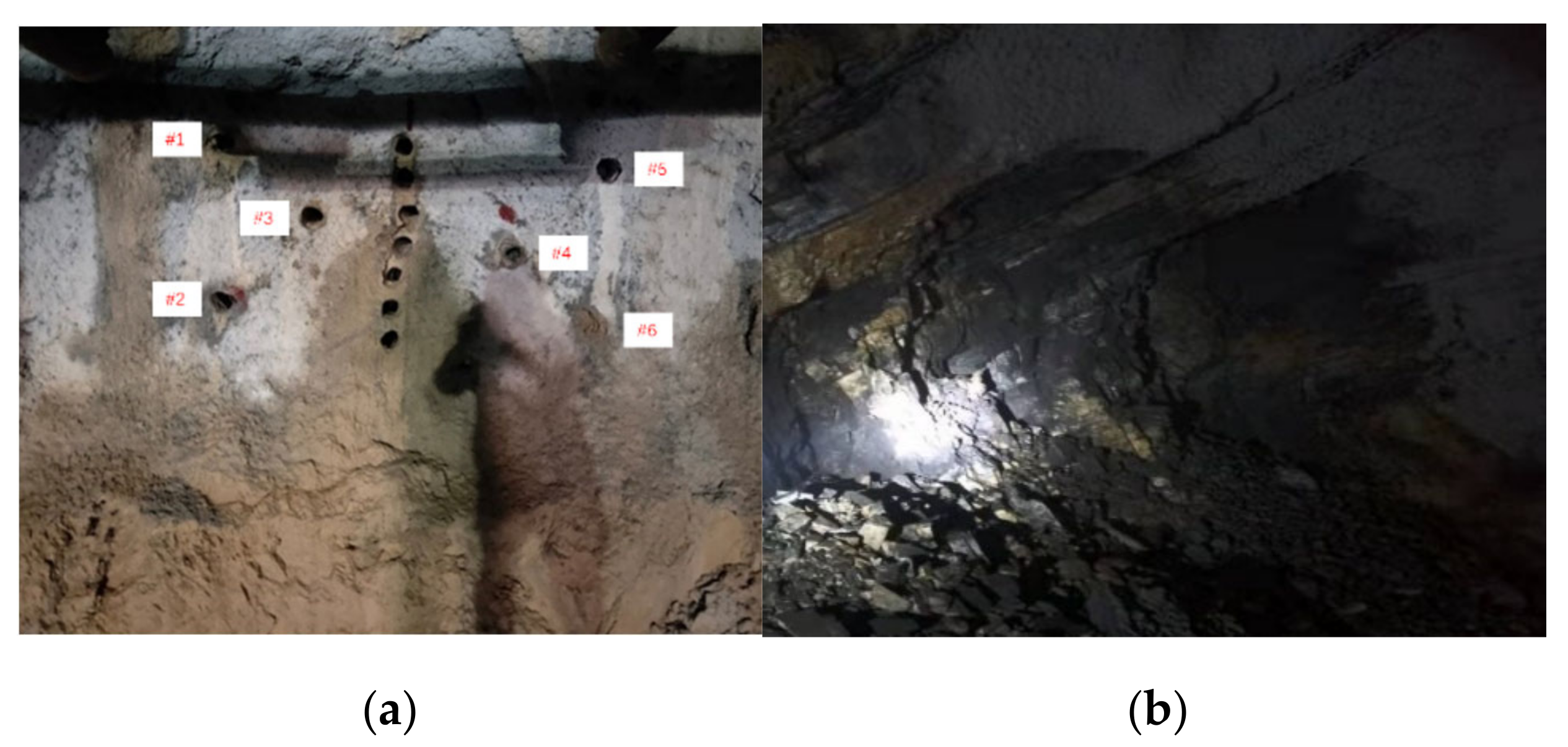
4.1. Results and Analysis of Cutting Excavation Tests

According to the design parameters in Table 2, cutting holes and empty holes were arranged on the tunnel face to conduct the first cutting excavation test. The comparison before and after cutting rock mass cracking was shown in Figure 8.
In Figure 8, the rock mass near cutting holes #1, #2 and #3 was basically spalling off after the high-pressure gas expansion rock mass cracking. There was a punching phenomenon in cutting hole #4, so the rock mass around the hole was not spalling off, but there was a small amount of fracture distributed around the hole. The section formed by rock mass cracking had an irregular shape, with a maximum width of 2.5 m, a maximum height of 4.0 m and an area of about 6.7 m2. The deepest depth of cutting space could reach 1.7 m. Some broken but not spalled rock mass were further processed by the gun machine and excavator. According to the statistics, the stripping rock volume in test 1 was about 4.3 m3. The field noise was slightly larger than expected due to the punching phenomenon in the test. The distribution of rock blocks after rock mass cracking at the site was shown in Figure 9.
In Figure 9, the distribution of the rock blocks was relatively scattered in the test, and the rock fragmentation ranged from 0.2–0.45 m. The farthest distance of the rock blocks from the tunnel face reached 20 m.
According to the design parameters in Table 2, cutting holes and empty holes were arranged on the tunnel face to conduct the second cutting excavation test. The comparison before and after cutting rock mass cracking was shown in Figure 10.
In Figure 10, the rock mass near cutting holes was basically spalling off after high-pressure gas expansion rock mass cracking. The section formed by rock mass cracking had an irregular shape, with a maximum width of 3.9 m, a maximum height of 2.8 m and an area of about 7.5 m2. The deepest depth of cutting space could reach 1.8 m. Some broken but not spalled rock mass was further processed by the gun machine and excavator. According to the statistics, the stripping rock volume in test 2 was about 6.7 m3. The field noise was moderate as expected in the test. The distribution area of large rock blocks is mainly within 3 m in front of the tunnel face, and occasionally small pieces of rock fragment flew 50 m away. The rock fragmentation ranged from 0.2–0.4 m.
Comparing the results of the two tests (see Table 4), it is concluded that the rock mass cracking effect of the cutting mode of “central vertical empty hole + double wedge cutting hole” is better than that of the cutting mode of “central vertical empty hole + single wedge cutting hole”. With the cutting mode of “central vertical empty hole + double wedge cutting hole”, the maximum depth of the cutting space is deeper, and the unit consumption is smaller, and the distribution of the rock blocks is relatively concentrated, and the rock fragmentation is relatively uniform. Therefore, in the upper step excavation tests, the cutting mode of “central vertical empty hole + double wedge cutting hole” was uniformly chosen for the cutting of the tunnel face.

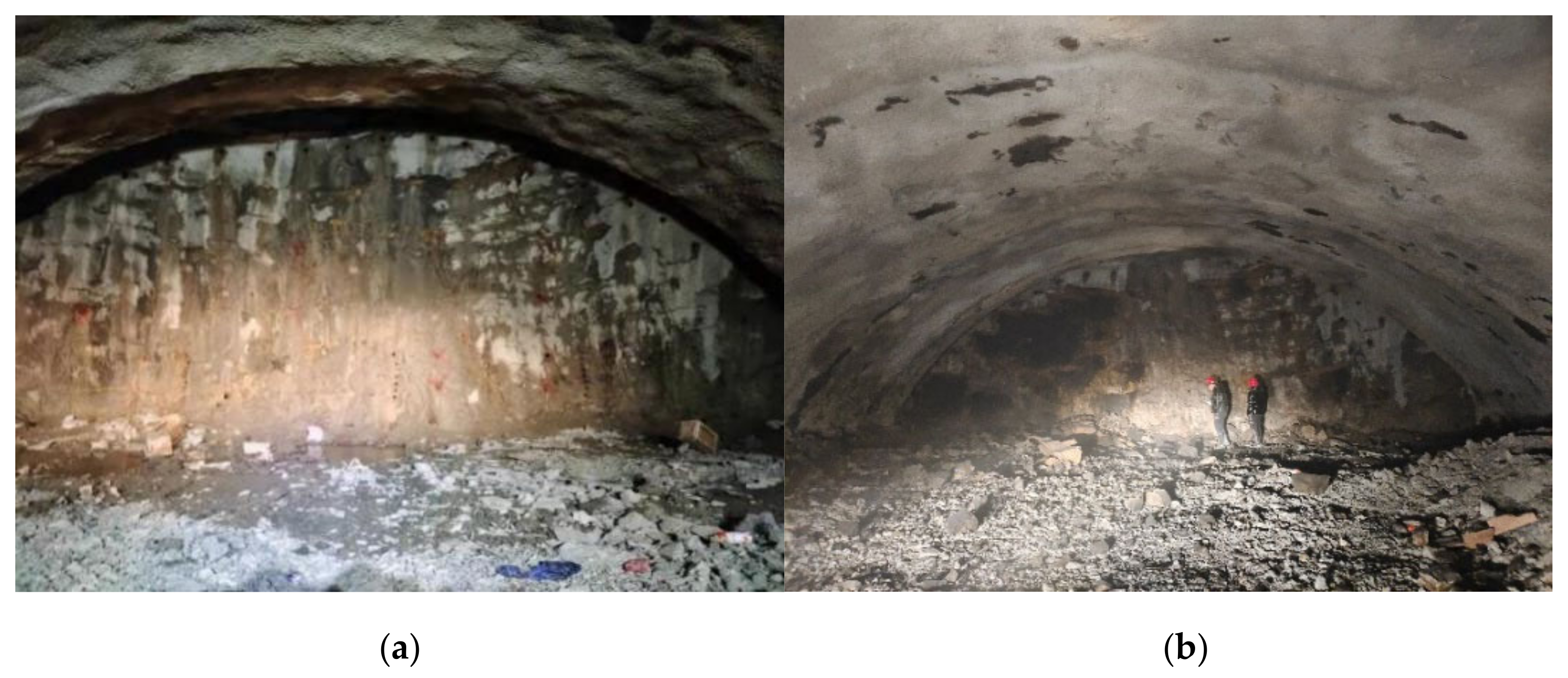
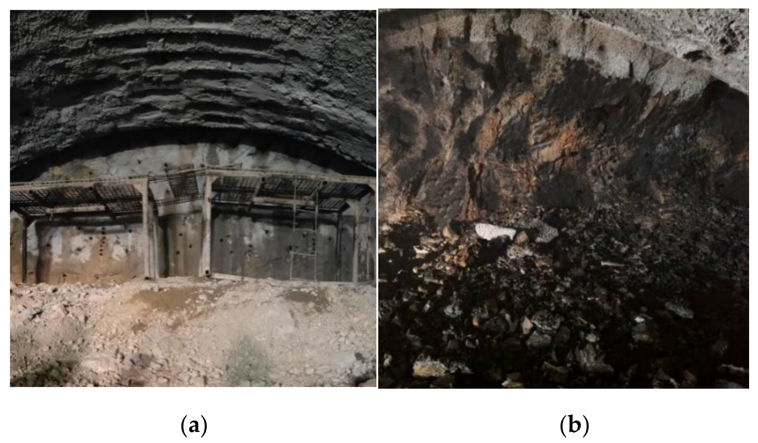
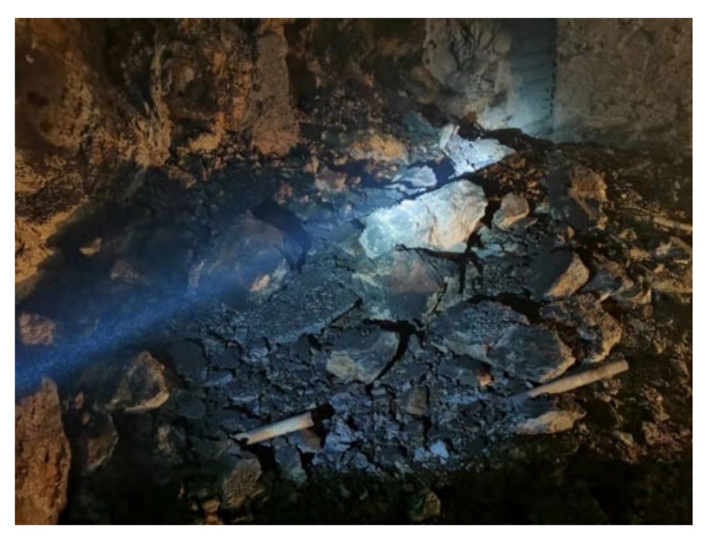
4.2. Results and Analysis of Upper Step Excavation Tests

According to the design parameters in Table 3, fracturing holes were arranged on the tunnel face to conduct the first upper step excavation test. The comparison before and after rock mass cracking was shown in Figure 11.
In Figure 11, the left area of the tunnel face basically achieved the ideal rock mass cracking effect after the high-pressure gas expansion rock mass cracking, and the rock mass in the charging area was basically spalling off with a longitudinal depth of about 1.4 m. There was only a small amount of rock mass spalling off in the middle and right area of the tunnel face, but there were fractures distributed around the hole. This was because the two cutting holes in the middle and right cutting areas could not be filled with the expansion pipe. The cutting area did not play the role of creating a free surface, resulting in a poor effect. Since there was no hydraulic gun machine further processing the tunnel face, some rock mass of the fractured area was not spalling off. Therefore, the stripping rock volume in test 3 was small and was about 22 m3. The field noise was moderate as expected in the test. The distribution area of most rock blocks is mainly within 3 m in front of the tunnel face, and the size of most rock blocks ranged from 0.25–0.6 m.
According to the design parameters in Table 3, fracturing holes were arranged on the tunnel face to conduct the second upper step excavation test. The comparison before and after rock mass cracking was shown in Figure 12.
In Figure 12, the tunnel face basically achieved the ideal rock mass cracking effect after the high-pressure gas expansion rock mass cracking, and the rock mass in the successful detonation area was basically spalling off with a longitudinal depth of about 1.5 m. There was a punching phenomenon in several holes, and only the 20–40 cm thickness of rock surface was spalling off. Some broken but not spalled rock mass was further processed by the gun machine and excavator. According to the statistics, the stripping rock volume in test 4 was about 39 m3. The distribution of rock blocks after rock mass cracking at the site was shown in Figure 13.
In Figure 13, the distribution area of most rock blocks is mainly within 3 m in front of the tunnel face, and the size of most rock blocks ranged from 0.2–0.5 m.
Comparing the results of the two tests (see Table 5), it is concluded that the rock mass cracking effect of the auxiliary hole network parameter of “0.8 m × 0.7 m” is better than that of the auxiliary hole network parameter of “1.0 m × 0.9 m” when the cutting mode of “central vertical empty hole + double wedge cutting hole” is chosen for the cutting of the tunnel face. In the successful detonation area, the longitudinal depth of rock mass cracking is deeper with the auxiliary hole network parameter of “0.8 m × 0.7 m”, which meets the requirement of the planned footage. In addition, the rock fragmentation is also relatively moderate and uniform. As the rock mass cracking effect of test 3 is greatly influenced by charging factors, the unit consumption of the two tests is not compared. Therefore, in the tunnel excavation, the rock mass cracking effect can meet the requirements with the cutting mode of “central vertical empty hole + double wedge cutting hole” and the auxiliary hole network parameter of “0.8 m × 0.7 m”.

4.3. Results and Analysis of Vibration Monitoring

After measurement, the horizontal distance between the entrance of Longmen Tunnel and the Great Wall is 85 m and the vertical distance is 93 m. The site location of the entrance of Longmen Tunnel and the Great Wall is shown in Figure 14.
In order to study the vibration impact of high-pressure gas expansion rock mass cracking excavation on the surrounding buildings and structures, two monitoring points were arranged on the flat ground surface outside the tunnel at 60 m and 80 m away from the tunnel face. The specific site arrangement of monitoring points and site photos are shown in Figure 15 and Figure 16. In order to avoid mistakenly picking up the vibration data caused by the falling rock blocks, the trigger level of the two blast vibration loggers was set to 0.10 cm/s in accordance with the Blasting Safety Regulations (GB6722-2014) [33] for the safe allowable vibration speed of general ancient buildings and historic sites.
After the excavation of high-pressure gas expansion rock mass cracking, it was found that two blast vibration loggers were not triggered, indicating that the vibration caused by the high-pressure gas expansion rock mass cracking test at the monitoring point was less than 0.10 cm/s. The vibration was less than 0.1 cm/s at 60 m, and the vibration continued to decay with the increase of distance. The horizontal distance between the entrance of Longmen Tunnel and the Great Wall is 85 m and the vertical distance is 93 m. The distance between the protected point of the Great Wall and the high-pressure gas expansion rock mass cracking point in the tunnel is always greater than 60 m—from 126 m at the beginning to 93 m when the rock mass cracking point is directly underneath the Great Wall. Therefore, during the construction of the tunnel under the Great Wall, the vibration caused by high-pressure gas expansion rock mass cracking will not cause damage to the Great Wall and meets the safe allowable vibration speed of general ancient buildings and historic sites. The high-pressure gas expansion rock-cracking technology has the advantage of little vibration.

5. Conclusions

Based on theoretical analysis and field tests, this paper studies the optimization of rock mass cracking parameters and the application of high-pressure gas expansion rock-cracking technology in hard rock tunnels. The main research results are as follows:
  • The rock mass cracking effect of the cutting mode of “central vertical empty hole + double wedge cutting hole” is better than that of the cutting mode of “central vertical empty hole + single wedge cutting hole”. The stripping rock volume in the cutting excavation can reach 6.7 m3 once with the cutting mode of “central vertical empty hole + double wedge cutting hole”. The rock fragmentation is relatively uniform and suitable, and the distribution of the rock blocks is relatively concentrated. It is proved that the high-pressure gas expansion rock-cracking technology can achieve ideal cutting rock mass cracking effect in hard rock tunnel with the proper cutting mode.
  • The rock mass cracking effect of the auxiliary hole network parameter of “0.8 m × 0.7 m” is better than that of the auxiliary hole network parameter of “1.0 m × 0.9 m”. The stripping rock volume in the upper step excavation can reach 39 m3 when the cutting mode of “central vertical empty hole + double wedge cutting hole” is used to match the auxiliary hole network parameter of “0.8 m × 0.7 m”. The rock fragmentation is relatively uniform, and the distribution area of rock blocks is mainly within 3 m in front of the tunnel face. It is proved that the high-pressure gas expansion rock-cracking technology can achieve an ideal excavation effect in hard rock tunnel with a suitable cutting mode and hole network parameters.
  • The blast vibration logger with the trigger lever of 0.1 cm/s was not triggered, which was at 60 m away from the rock mass cracking point. It indicates that the vibration of monitoring point is less than 0.10 cm/s, which meets the safe allowable vibration speed of general ancient buildings and historic sites. It is proved that the high-pressure gas expansion rock-cracking technology can realize the safe and environmentally friendly excavation of hard rock tunnel under the Great Wall. As long as there is the high quality of hole plugging and no punching, the high-pressure gas expansion rock-cracking technology has the advantages of little vibration, low noise and less flying rocks.
  • High-pressure gas expansion rock-cracking technology can realize the safe and efficient excavation of hard rock tunnel, and the vibration generated by its rock-cracking process does not affect the safety of the Great Wall. This is the first application for the continuous non-explosion excavation of hard rock tunnel near historic sites. It brings a new idea of rock cracking for hard-rock projects located in the city center, near important buildings or in other complex construction environments. In this paper, the excavation plan of the hard rock tunnel near the historic site is formed around high-pressure gas expansion rock-cracking technology. However, the plugging technology needs to be further improved to raise the efficiency and quality of plugging, so as to provide a high guarantee for the rock-cracking effect of high-pressure gas expansion rock-cracking technology.

Author Contributions

Conceptualization, D.L.; methodology, D.L.; software, C.W.; validation, C.W., Y.T. and H.C.; data curation, H.C.; writing-original draft preparation, D.L. and C.W.; writing-review and editing, D.L. and C.W.; visualization, H.C.; supervision, Y.T.; project administration, Y.T. All authors have read and agreed to the published version of the manuscript.

Funding

This research received no external funding.

Institutional Review Board Statement

Not applicable.

Informed Consent Statement

Not applicable.

Data Availability Statement

Data will be made freely available on request.

Acknowledgments

The authors would like to thank China Communications Road and Bridge Construction Co., especially Jia Wen, Yu Jia, and Songzhou Chen of the company for their assistance in site investigation and field tests.

Conflicts of Interest

The authors declare no conflict of interest.

References

  1. Jafri, T.H.; Yoo, H. REV Application in DEM Analysis of Non-Vibrational Rock Splitting Method to Propose Feasible Borehole Spacing. Appl. Sci. 2018, 8, 335. [Google Scholar] [CrossRef] [Green Version]
  2. De Graaf, W.W.; Spiteri, W. A preliminary qualitative evaluation of a hydraulic splitting cylinder for breaking rock in deep-level mining. J. South. Afr. Inst. Min. Metall. 2018, 118, 891–897. [Google Scholar] [CrossRef]
  3. Qiu, Z.G.; Ji, Y.; Zhang, F.P.; Yan, G.L. Experimental Investigation and Numerical Modeling of Elastic Modulus Variation with Stress during Hydration and Expansion Process of Static Cracking Agent. Appl. Sci. 2021, 11, 3955. [Google Scholar] [CrossRef]
  4. Hao, B.Y.; Huang, H.; Feng, Z.J.; Wang, K. The Static Breaking Technique for Sustainable and Eco-Environmental Coal Mining. Sci. World J. 2014, 14, 248792. [Google Scholar]
  5. Wang, S.G.; Zhu, S.Y.; Yuen, P.L. Assessment of Ground-Borne Vibration Impact on Nearby Underground Facilities Induced by Ground Surface Excavation. J. Constr. Div. Am. Soc. Civ. Eng. 2021, 147, 04021071. [Google Scholar] [CrossRef]
  6. Yoon, B.J.; Lee, K.S.; Lee, J.H. A Novel Predictable Rock Breaker Using Intelligent Hydraulic Control with ICT Convergences. Appl. Sci. 2019, 9, 3333. [Google Scholar] [CrossRef] [Green Version]
  7. Qiu, W.; Zhang, G.S.; Fan, K.; Li, X.; Ma, G.Z. Construction Technology with Boom Type Heading Applied to Unsymmetrical Pressure Shallow Depth and Large Span Tunnel. Min. Constr. Technol. 2021, 42, 16–20. [Google Scholar]
  8. Xiao, Y.; Yang, Q.X.; Jiang, Y.J. Numerial Simulation Analysis of Milling Parameters with Tunnel Milling Excavation Method. Railw. Std. Des. 2016, 60, 100–104. [Google Scholar]
  9. Zhang, Y.N.; Deng, H.W.; Ke, B.; Gao, F. Research on the Explosion Effects and Fracturing Mechanism of Liquid Carbon Dioxide Blasting. Min. Metall. Explor. 2022, 39, 521–530. [Google Scholar] [CrossRef]
  10. Zeng, Y.Q.; Li, H.B.; Xia, X.; Deng, S.C.; Zuo, H.; Yue, H.Z.; Luo, H. Research on Time-frequency Characteristics for Blasting Vibration Signal of CO2 Blasting by Frequency Slice Wavelet Transform. Eng. Lett. 2020, 28, 1047–1057. [Google Scholar]
  11. Wang, B.; Li, H.B. Numerical simulation of rock fractures induced by CO2 blasting. IOP Conf. Ser. Earth Environ. Sci. 2021, 861, 042065. [Google Scholar] [CrossRef]
  12. Xia, J.Q.; Dou, B.; Tian, H.; Zheng, J.; Cui, G.D.; Kashif, M. Research on Initiation of Carbon Dioxide Fracturing Pipe Using the Liquid Carbon Dioxide Phase-Transition Blasting Technology. Energies 2021, 14, 521. [Google Scholar] [CrossRef]
  13. Yuan, H.L.; Chen, C.; Yu, J.X.; Liu, X.Y.; Dong, B. Liquid CO2 Phase Change Fracturing and Vibration Monitoring in Roadbed Slope Excavation. J. Phys. Conf. Ser. 2021, 50, 012116. [Google Scholar]
  14. Jia, J.Z.; Wang, D.M.; Li, B.; Tian, X.Y. Study of the influencing factors of the liquid CO2 phase change fracturing effect in coalseams. PLoS ONE. 2021, 16, 0254996. [Google Scholar] [CrossRef]
  15. Sui, H.Y.; Su, T.M.; Hu, R.L.; Yang, K.; Cheng, Y.X. Liquid CO2 Phase-Transition Rock Fracturing: A Novel Technology for Safe Rock Excavation. Appl. Sci. 2022, 12, 68. [Google Scholar] [CrossRef]
  16. Li, Q.Y.; Chen, G.; Luo, D.Y.; Ma, H.P.; Liu, Y. An experimental study of a novel liquid carbon dioxide rock-breaking technology. Int. J. Rock Mech. Min. Sci. 2020, 128, 104244. [Google Scholar] [CrossRef]
  17. Li, B.L.; Wang, E.Y.; Hu, S.B.; Wang, X.F.; Liu, B. A Study of Vibration Velocity Attenuation Induced by Pneumatic Rock Breaking with Carbon Dioxide Ice Powder for Safety Assessment. Rock Mech. 2021, 54, 6481–6493. [Google Scholar] [CrossRef]
  18. Zhang, Y.N.; Deng, J.R.; Deng, H.W.; Ke, B. Peridynamics simulation of rock fracturing under liquid carbon dioxide blasting. Int. J. Damage Mech. 2019, 28, 1038–1052. [Google Scholar] [CrossRef]
  19. Zhang, Y.N.; Deng, J.R.; Ke, B.; Deng, H.W.; Li, J.L. Experimental Study on Explosion Pressure and Rock Breaking Characteristics under Liquid Carbon Dioxide Blasting. Adv. Civ. Eng. 2018, 11, 7840125. [Google Scholar] [CrossRef]
  20. Ke, B.; Zhou, K.P.; Ren, G.F.; Shi, J.; Zhang, Y.N. Positive Phase Pressure Function and Pressure Attenuation Characteristic of a Liquid Carbon Dioxide Blasting System. Energies 2019, 12, 4134. [Google Scholar] [CrossRef] [Green Version]
  21. Liu, D.W.; Jian, Y.H.; Zhang, Z.L.; Zhang, S.; Huang, Z.; Chen, S.J. High Pressure Gas Expansion Fracturing Excavation Method for the Contact Channel of Urban Metro in Hard Rock Strata. CN109736827B, 31 January 2020. [Google Scholar]
  22. Liu, D.W.; Tang, Y.; Xu, Q.; Cao, M.; Jiang, S.L.; Zhang, J.J. A Method for Testing the Cumulative Damage to the Surrounding Rock with High Pressure Gas Expansion Rock Cracking Method in Hard Rock. CN111781277B, 2 November 2021. [Google Scholar]
  23. Peng, H.D.; Liu, D.W.; Chu, F.J.; Jian, Y.H. Test on High Pressure Gas Expansion Rock Cracking in Hard Rock Tunnel. Rock Soil Mech. 2018, 39, 242–248. [Google Scholar]
  24. Liu, D.W.; Zhang, Z.L.; Chu, F.J.; Jian, Y.H.; Zhang, S.; Huang, Z. Cutting Tests of High Pressure Gas Expansion Rock-breaking Technology in Urban Small Cross-section Hard Rock Tunne. Blasting 2019, 36, 104–111. [Google Scholar]
  25. Liu, D.W.; Tang, Y.; Cai, C.W.; Jian, Y.H. A Rock Fracturing Method Using High-Pressure Gas Expansion: Case Study on Its Application in Hangzhou-Lin’an Intercity Railway. Adv. Civ. Eng. 2021, 14, 6654471. [Google Scholar] [CrossRef]
  26. Peng, H.D.; Chu, F.J.; Yang, G.; Chen, Z.; Peng, Y.J. Effective Level Evaluation of Rock Breaking of Tunnel High Pressure and Engineering Application. Blasting 2018, 35, 164–170. [Google Scholar]
  27. Liu, D.W.; Qiu, F.K.; Jia, H.R.; Zhang, Z.L.; Huang, D.H. Safety Evaluation of Excavation Construction with High Pressure Gas Expansion Method of Subway Liaison Channel. J. Saf. Environ. 2019, 19, 1511–1517. [Google Scholar]
  28. Liu, D.W.; Tang, Y.; Zhang, J.J.; Zhang, W.M. A Gas-Thermal Expansion Pipe Rock-breaking Device and Its Rock-Breaking Method. CN113091545A, 9 July 2021. [Google Scholar]
  29. Liu, J.P.; Han, Z.W.; Liu, X.B.; Su, Y.; Bi, X.L. A Kind of Thermal Expansion Rock Splitting Agent. CN104961387B, 25 January 2017. [Google Scholar]
  30. Ma, D.; Duan, H.; Zhang, J.; Liu, X.; Li, Z. Numerical simulation of water-silt inrush hazard of fault rock: A three-phase flow model. Rock Mech. 2022, 55, 5163–5182. [Google Scholar] [CrossRef]
  31. Ma, D.; Duan, H.; Zhang, J. Solid grain migration on hydraulic properties of fault rocks in underground mining tunnel: Radial seepage experiments and verification of permeability prediction. Tunn. Undergr. Space Technol. 2022, 126, 104525. [Google Scholar] [CrossRef]
  32. Ma, D.; Duan, H.; Zhang, J.; Bai, H. A state-of-the-art review on rock seepage mechanism of water inrush disaster in coal mines. Int. J. Coal Sci. Technol. 2022, 9, 50. [Google Scholar] [CrossRef]
  33. GB 6722-2014; Safety Regulations for Blasting. China Standard Press: Beijing, China, 2014.
Figure 1. Structure schematic drawing and product picture of expansion pipe. (a) Structure schematic drawing; (b) Product picture.
Applsci 13 01017 g001
Figure 2. The operating principle of expansion pipe (vertical view).
Applsci 13 01017 g002
Figure 3. Rock failure mode of uniaxial compression test. (a) Sample A-1; (b) Sample A-2; (c) Sample A-3.
Applsci 13 01017 g003
Figure 4. Rock failure mode of Brazilian splitting test. (a) Sample B-1; (b) Sample B-2; (c) Sample B-3.
Applsci 13 01017 g004
Figure 5. Stress–strain curve. (a) Uniaxial compression; (b) Brazilian splitting.
Applsci 13 01017 g005
Figure 6. Plane and section arrangement of cutting mode. (a) Test 1; (b) Test 2.
Applsci 13 01017 g006
Figure 7. Plane arrangement of fracturing holes in the upper step excavation tests. (a) Test 3; (b) Test 4.
Applsci 13 01017 g007
Figure 8. The comparison before and after cutting rock mass cracking in test 1. (a) Tunnel face before cutting rock mass cracking; (b) Tunnel face atter cutting rock mass cracking.
Applsci 13 01017 g008
Figure 9. The distribution of rock blocks after rock mass cracking in the test 1.
Applsci 13 01017 g009
Figure 10. The comparison before and after cutting rock mass cracking in test 2. (a) Tunnel face before cutting rock mass cracking; (b) Tunnel face atter cutting rock mass cracking.
Applsci 13 01017 g010
Figure 11. The comparison before and after rock mass cracking in the test 3. (a) Tunnel face before rock mass cracking; (b) Tunnel face atter rock mass cracking.
Applsci 13 01017 g011
Figure 12. The comparison before and after rock mass cracking in test 4. (a) Tunnel face before rock mass cracking. (b) Tunnel face after rock mass cracking.
Applsci 13 01017 g012
Figure 13. The distribution of rock blocks after rock mass cracking in the test 4.
Applsci 13 01017 g013
Figure 14. The site location of the entrance of Longmen Tunnel and the Great Wall.
Applsci 13 01017 g014
Figure 15. Arrangement of monitoring. points.
Applsci 13 01017 g015
Figure 16. Site photos of vibration monitoring. (a) Monitoring point 1; (b) Monitoring point 2.
Applsci 13 01017 g016
Table 1. Rock mass cracking parameters of the tests.
Category of Fracturing HoleHole Diameter (mm)Hole Depth (m)Hole Spacing (m × m)Single-Hole Charge (kg)
Cutting hole702.1/1.3
Auxiliary hole701.81.0 × 0.9, 0.8 × 0.71.0
Table 2. Test parameters of cutting excavation.
Test NumberCutting ModeHole CategoryHole Diameter (mm)Hole Depth (m)Quantity of HolesAngles (°)Charge (kg)Charge Length (m)
1Single wedgeCutting hole702.14841.31.0
Empty hole701.81090//
2Double wedgeCutting hole702.16841.31.0
Empty hole701.81090//
Table 3. Test parameters of upper step excavation.
Test NumberHole CategoryHole Diameter (mm)Hole Depth (m)Network Parameter (m × m)Quantity of HolesAngles (°)Charge (kg)Charge Length (m)
3Cutting hole702.1/18841.31.0
Empty hole701.8/3090//
Auxiliary hole701.81.0 × 0.944901.00.8
4Cutting hole702.1/18841.31.0
Empty hole701.8/3090//
Auxiliary hole701.80.8 × 0.750901.00.8
Table 4. Results of cutting excavation tests.
Test NumberCutting ModeQuantity of Expansion PipeMass of Gas-Generating Agent (kg)Depth of Cutting Space (m)Stripping Rock Volume (m3)Unit Consumption (kg·m−3)Rock Fragmentation (m)
1Single wedge45.21.74.31.210.2–0.45
2Double wedge67.81.86.71.160.2–0.4
Table 5. Results of upper step excavation tests.
Test NumberNetwork Parameter (m × m)Quantity of Expansion PipeMass of Gas-Generating Agent (kg)Depth (m)Stripping Rock Volume (m3)Unit Consumption (kg·m−3)Rock Fragmentation (m)
31.0 × 0.96267.41.4223.060.25–0.6
40.8 × 0.76873.41.5391.880.2–0.5
Disclaimer/Publisher’s Note: The statements, opinions and data contained in all publications are solely those of the individual author(s) and contributor(s) and not of MDPI and/or the editor(s). MDPI and/or the editor(s) disclaim responsibility for any injury to people or property resulting from any ideas, methods, instructions or products referred to in the content.

