Article

Seismic Response Analysis of Rock-Socketed Piles in Karst Areas under Vertical Loads

1
School of Civil Engineering, Shandong Jianzhu University, Jinan 250101, China
2
State Key Laboratory of Hydraulic Engineering Simulation and Safety, Tianjin University, Tianjin 300072, China
*
Authors to whom correspondence should be addressed.
Appl. Sci. 2023, 13(2), 784; https://doi.org/10.3390/app13020784
Submission received: 9 December 2022 / Revised: 1 January 2023 / Accepted: 3 January 2023 / Published: 5 January 2023
(This article belongs to the Special Issue Geotechnical Earthquake Engineering: Current Progress and Road Ahead)

Abstract

:
Karst landforms constitute one of the most harmful geological conditions, which have an adverse effect on the deep foundation structures of bridges. During earthquakes, the existence of karst caves can cause serious seismic damage to the bridge pile foundation. In order to investigate the seismic response of rock-socketed piles under vertical loads in complex karst cave conditions, finite element numerical simulation analyses were carried out, referring to the practical major bridge structure rock-socketed pile project in China. The peak strain distributions of rock-socketed pile foundation influenced by single-karst cave factors under the combined action of vertical loads and ground motions were investigated, and the influences of complex multi-caves were further explored. The results showed that the restraint effect of the bedrock near the pile would gradually decrease with the increase of the height of the karst cave and the decrease of the height of the karst cave roof; under the condition of a beaded karst cave, the constraint of bedrock between the karst caves makes the pile present the distribution characteristics of “multi-segment and multi-broken line”; under the condition of an underlying karst cave, the existence of the underlying karst cave would decrease the restraint of the bedrock at the bottom pile and increase the peak strain of the pile to a certain extent. This paper revealed the seismic response law of the rock-socketed pile under vertical loads within various complex karst cave conditions and developed reasonable reinforcement measures aiming at dangerous locations, providing important engineering guidance and a reference for the seismic design of rock-socketed pile foundation in complex karst areas.

1. Introduction

The goal to build a country with a strong transportation network has encouraged the construction of China’s modern, comprehensive transportation system to flourish. Karst landforms constitute a kind of harmful geological condition that has an adverse impact on traffic engineering construction, especially the construction of the deep foundation of bridges. They not only induce many technical difficulties to the construction of the bridge infrastructure, but also bring risks to the safe operation of the infrastructure and even serious economic losses [1,2,3].
During earthquakes, the seismic performance of piles influences the effects on the upper bridge, and, therefore, the investigation on the seismic responses of piles is one of the most important research objects in geotechnical and earthquake engineering [2,4]. Focusing on the slope angle and the elastic modulus of the slope-pile, Zeng investigated the seismic response characteristics of a slope rock-socketed pile, employing pseudo-static tests [5]. Rajeswari and Sarkar investigated the seismic behavior of pile groups embedded in liquefiable soil, and the performance of pile groups was investigated for the fixed and pinned pile to cap connections for both floating and end bearing types of pile groups [6]. Phung et al. investigated the free vibration analysis on the seismic responses of piles, and promoted a new method for road and bridge engineering [7,8,9]. According to these excellent papers, the seismic responses of piles in the general soil layers have been widely investigated [4]. However, the investigation of seismic responses of rock-socketed piles in karst areas are very rare [10,11].
Since the geological structure of karsts is complicated, piles are widely used for the substructure of important projects in karst areas [4]. In a karst landform, there is a number of karst caves in the field, which can influence the bearing capacity of the foundation; additionally, the scales of karst caves (such as the height and span) are most important influencing factors [12]. Due to the different lithology of the rock mass, the different development of a karst cave, and the complexity and diversity of the filling, the pile in the karst section is prone to large displacement to affect the stability of the superstructure during earthquakes [4]. Furthermore, the seismic responses of rock-socketed piles would also be complicated due to the existence of karst caves. Were rock-socketed piles built passing through karst caves, the scales and positions of karst caves would highly influence the seismic response characteristics and failure mechanism of the rock-socketed piles. Therefore, the investigations on the seismic responses of rock-socketed piles are revealing and essential.
In this paper, the seismic responses of the rock-socketed pile under complicated karst conditions and vertical loads were investigated, referring to a major bridge structure in a karst area in China. The finite element models of rock-socketed piles with different karst conditions were established, and the seismic characteristics and failure mechanisms of rock-socketed piles were investigated considering the effect of the vertical load. The comprehensive strain analyses of the pile under the conditions of different karst cave heights, different karst cave roof heights, the through-pile karst cave, and the underlying karst cave were carried out. The list of symbols in paper is shown in Table 1. The research results are helpful to develop the key construction technology of deep-pile foundations in strong development karst areas, and have theoretical significance and engineering value for improving the design and construction of bridge pile foundations in karst areas.

2. Finite Element Model of the Rock-Socketed Pile and Seismic Input

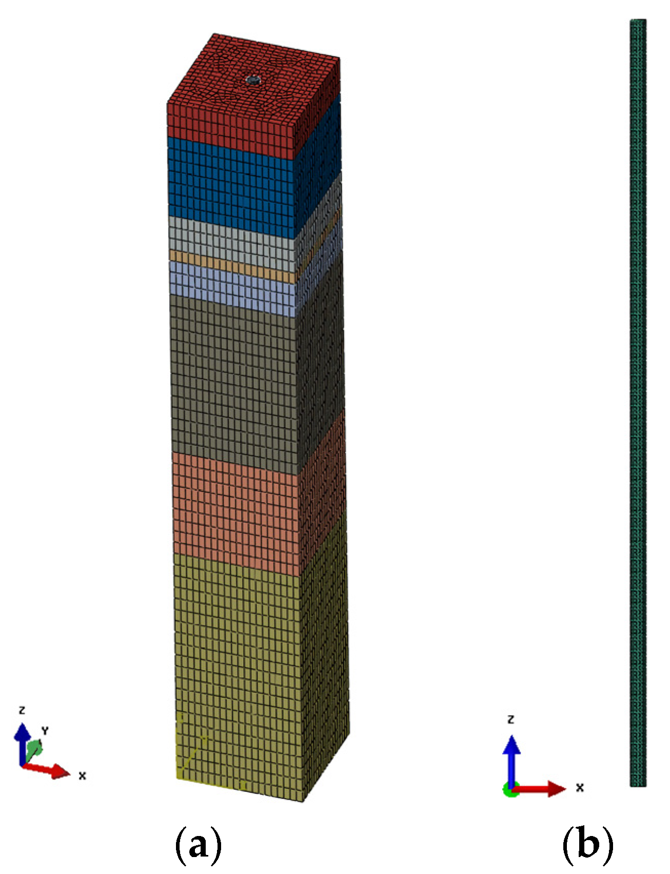
2.1. Finite Element Model

The project is in the Plain of North China and passes through the high-water level seismic liquefaction area in a large range along the line. The karst develops in varied ways, the geological conditions are complex, and the construction is difficult. This paper mainly studied the numerical simulation of a major bridge structure rock-socketed pile project in a karst area. According to the geological survey report of the actual working conditions, the material parameters of each soil layer are shown in Table 2.
The finite element ABAQUS includes a rich library of linear and nonlinear material models, which can accurately simulate the nonlinear constitutive relationship between sand and bedrock under actual working conditions. Its powerful nonlinear analysis function can better simulate and solve the problems of material nonlinearity, geometric nonlinearity, and state nonlinearity in the pile–soil dynamic interaction [10]. Therefore, the numerical analysis modeling of the pile–soil system was established by using the large-scale general software of finite element ABAQUS in this paper [13]. The cross-section of the pile is circular with a radius of 1 m and the length of the pile is 100 m. Therefore, the soil foundation 20 m × 20 m × 120 m along three directions, which is great enough in the dynamic analysis. The finite element models of the soil and pile are shown in Figure 1. In this investigation, the karst cave was simulated by the equivalent materials, in which the unit weight and elastic modulus were approximately zero. The pile shaft damping ratio was 5%, which is widely adopted in the concrete material [14]. According to the actual engineering situation, the vertical load on the top of the pile foundation was calculated to be 18,000 kN. The nonlinear Interaction in ABAQUS was used to simulate complex nonlinear interaction features and displacement coordination between the pile and soil; the hard contact and thepenalty friction with a good value of 0.3 were employed in the normal direction and tangential direction, respectively [13].
In this investigation, the Mohr–Columb elastoplastic constitutive model was adopted for the sandy soil foundation [13], the Drucker–Prager elastoplastic constitutive model was adopted for bedrock [13], and the linear elastic constitutive model was adopted for pile. The Mohr–Columb model is suitable for nonlinear, elastoplastic soil materials, and has been widely used in geotechnical engineering. In the stress space, the yield surface of the Mohr–Columb condition is an irregular hexagonal cone, and the corresponding yield curve is a closed irregular hexagon in the plane π . The applicability of the Mohr–Columb yield criterion with constant cohesion c and internal friction angle φ becomes worse. The stress state of any point of soil material should meet the following [13]:
σ 1 = 2 c cos φ 1 sin φ + 1 + sin φ 1 sin φ σ 3
From Mohr’s circle, it can be concluded that [13]
τ = s cos φ
σ = σ m + s sin φ
The Mohr–Columb yield criterion can be rewritten as follows [13]:
s + σ m sin φ c cos φ = 0
In which s = σ 1 σ 3 / 2 ; σ m = σ 1 + σ 3 / 2 . The Mohr–Columb constitutive model used by ABAQUS in this paper is an extension of the classical Mohr–Coulomb yield criterion, which can specify the hardening and softening of materials according to relevant requirements. The yield surface equation is as follows: [13]:
F = R m c q q tan φ c = 0
where, φ is the friction angle of the material, c is the change process of the cohesion of the material according to the isotropic softening and hardening mode, and the partial hardness coefficient R m c is defined as follows [13]:
R m c ( θ , φ ) = 1 cos φ 3 sin θ + π 3 + 1 3 cos θ + π 3 tan φ
where, θ is the polar angle, which is defined as follows [13]:
cos 3 θ = r q 3
In this formula, r is the third stress invariant, q is the Mises equivalent stress. The bedrock adopted the Drucker–Prager elastoplastic constitutive model, which is based on the Drucker–Prager strength criterion proposed by American scientists Drucker and Prager in 1952. The Drucker–Prager model is used in ABAQUS [13]. The Drucker–Prager model can simulate soil nonlinearity very well, but it is advised that material response should be simulated under monotonic loading. The Drucker–Prager model allows a material to harden and/or soften isotropically. For granular materials, these models are often used as a failure surface, in the sense that the material can exhibit unlimited flow when the stress reaches yield. This behavior is called perfect plasticity. The models are also provided with isotropic hardening. In this case, plastic flow causes the yield surface to change size uniformly with respect to all stress directions. This hardening model is useful for cases involving gross plastic straining, or when the strain at each point is essentially in the same direction within the strain space throughout the analysis. Therefore, the Drucker–Prager model is widely employed in seismic analysis, and the feasibility of its employment has been evidenced in studies [14,15].

2.2. Seismic Input

In the actual working condition, 80 m above the rock is the cohesive sand layer with the shear wave velocity of the site less than 150 m/s. It is judged that the site is the fourth type of site, so the applicable Northridge wave was selected as the input ground motion, the peak value of the seismic wave is 0.2 g, and the acceleration time history and acceleration response spectrum of the seismic wave are shown in Figure 2. In Figure 2b, the response spectra data of the Northridge earthquake were all always positive due to the absolutization of acceleration values, and the fundamental period of the earthquake was approximately 0.75 s.
In order to ensure the rationality of the seismic input of the pile–soil system, viscoelastic artificial boundary conditions and the wave input method were adopted in this study. The viscoelastic artificial boundary is a stress-type local artificial boundary, which has good frequency stability and can accurately simulate the elastic recovery ability of semi-infinite media outside the truncated boundary. Due to the convenient application of this boundary condition and its easy combination with general finite element software, the viscoelastic artificial boundary has been widely used in finite element analysis and calculation of foundation structure dynamic interaction [16]. According to the derivation of the wave equation in the spherical coordinate system in references [17,18], it is concluded that the conditions of displacement and force on the viscoelastic artificial boundary are exactly the same as those of the original infinite medium, so only springs and dampers with corresponding parameters are needed to realize the viscoelastic artificial boundary. The spring coefficient and damping coefficient of the equivalent physical system on the viscoelastic boundary are respectively shown in the following formulas:
In the normal direction:
K n = α n G / R           C n = ρ c p
In the tangent direction:
K τ = α τ G / R           C τ = ρ c s
where, K n and C n are the coefficients of spring and damper in the normal direction, respectively. K τ and C τ are the coefficients of the spring and damper in the tangent direction, respectively. α n and α τ are the correction coefficients of the spring in the the normal direction and tangent direction, respectively. R is the distance from each boundary point to the force loading point [16]. G and ρ are the shear modulus and density of the medium, respectively; c p and c s are the propagation velocities of compression wave and shear wave in the medium, respectively [16]. In the whole system of the pile foundation in sandy soil, it is necessary to further calculate the displacement field, velocity field, and stress field caused by wave propagation in the medium so as to realize the viscoelastic artificial boundary and wave input method [18].

3. Seismic Response Analysis of the Rock-Socketed Pile under the Influence of a Single-Karst Cave

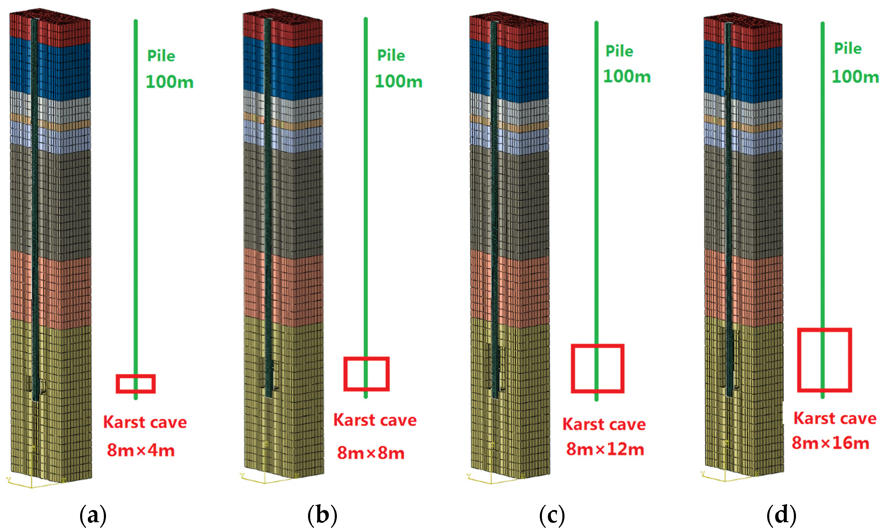
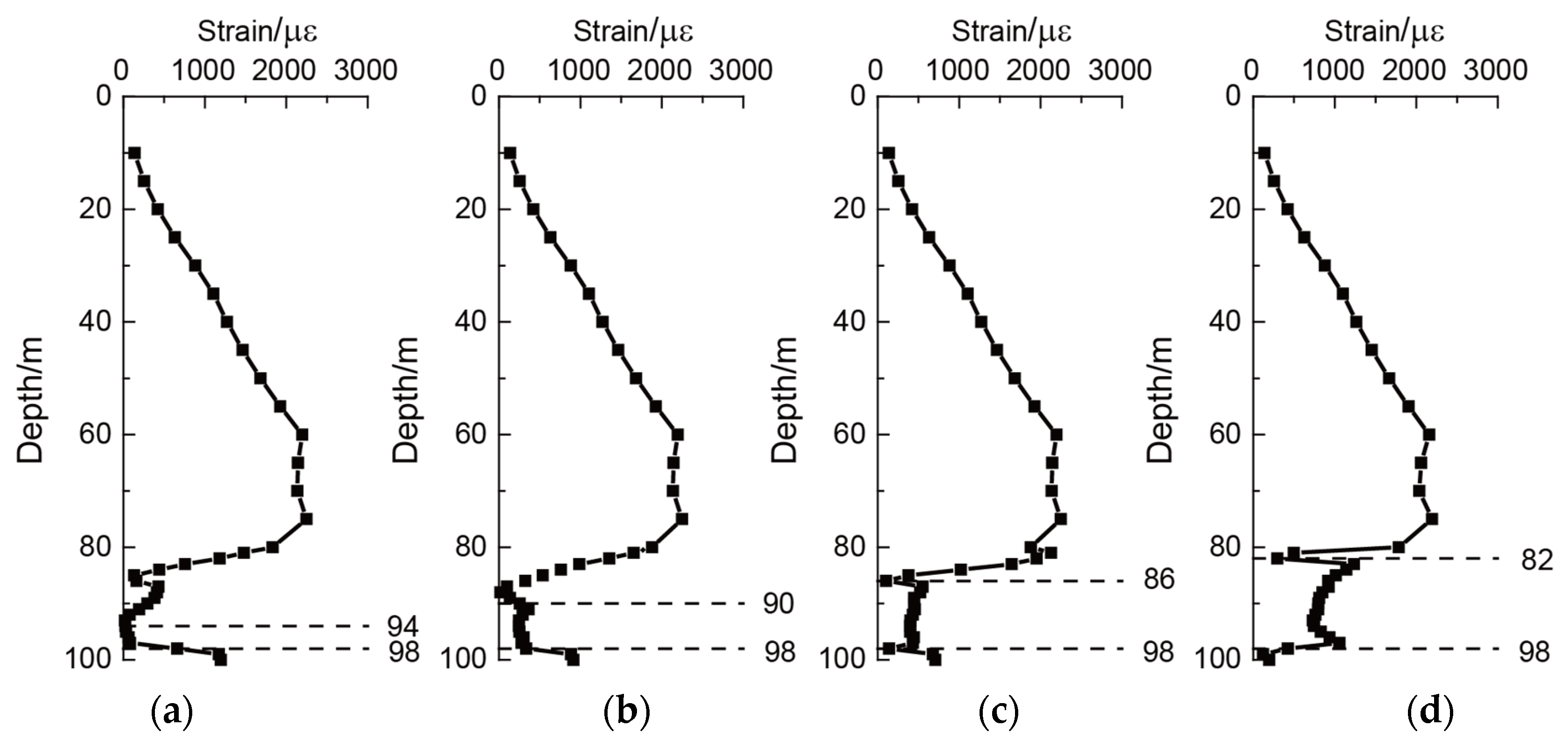
3.1. Analysis of the Rock-Socketed with Different Heights of the Karst Cave

In order to compare the influence of different karst cave heights on the strain law of the pile foundation, the width of the karst cave was 8 m, and the four working conditions of karst cave height, i.e., 4 m, 8 m, 12 m, and 16 m, were selected. The elevation of the karst cave’s base was 98 m deep, and the schematic diagram of the finite element model is shown in Figure 3. One measuring point every 5 m at the clay soil layer and one measuring point every 1 m at the bedrock (to obtain the strain law of pile in the karst cave) were designed. The distribution law of the peak strain of the pile with the buried depth under different conditions is shown in Figure 4.
By analyzing the strain peak value and curve strain law of the abovementioned finite element models with different cave heights, the strain distribution law of the pile was shown as relatively similar at the cohesive soil layer with a buried depth of more than 80 m. This is because the soil layer distribution conditions are the same. Under the action of the earthquake, the constraint of soft soil layer on the concrete pile was small. Moreover, under the action of vertical load, the maximum strain of the pile showed a gradually increasing trend, and the strain at the soil rock interface at 80 m was the most prominent. In the karst cave, the strain of the pile showed a distribution law of large at both ends and small in the middle. This is mainly caused by the strong restraint effect of the top and bottom positions of the karst cave on the pile. With the increase of the height of the karst cave, the peak strain of the pile in the karst cave increased significantly. The analysis shows that the free part of the pile inside the karst cave became larger, resulting in a relatively large strain deformation of the pile.

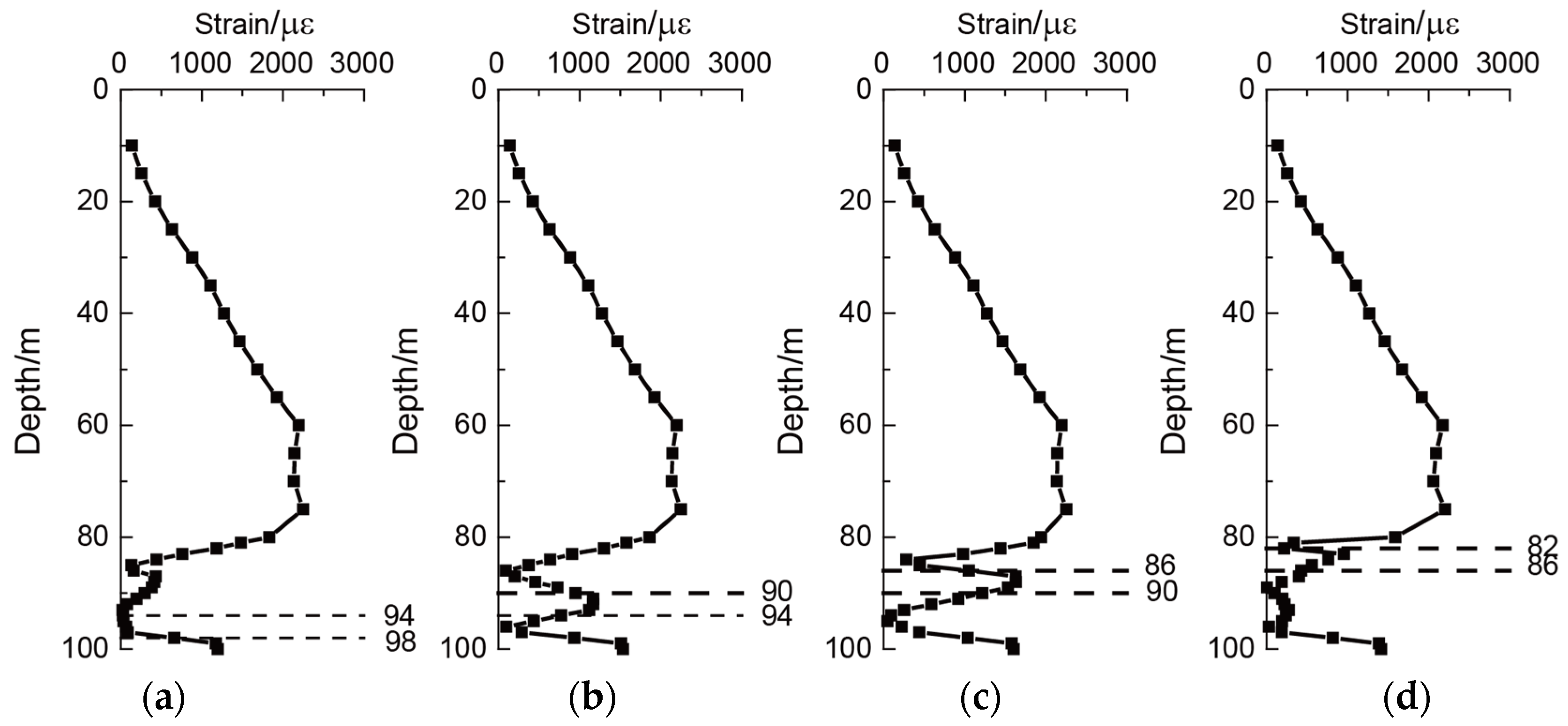
3.2. Analysis of the Rock-Socketed with Different Heights of the Karst Cave Roof

In this section, the height of the karst cave was 4 m and the width of the karst cave was 8 m. In order to compare the influence of the height of the bedrock roof above different karst caves on the strain law of the pile foundation, the elevation of the karst cave base was changed. The elevations were 98 m, 94 m, 90 m, and 86 m, respectively. The schematic diagram of the finite element model is shown in Figure 5. The distribution law of the peak strain of the pile shaft with buried depth under different working conditions is shown in Figure 6.
By analyzing the strain peak value and curve strain law of the abovementioned finite element models at different karst cave roof heights, when the height and width of a karst cave were fixed, the joint action of vertical load and seismic load was set; changing the height of the bedrock at the top of the karst cave also has a significant impact on the strain of rock-socketed piles. As the height of the roof decreased (the position of the karst cave floor increased), the sudden change of the strain of the rock-socketed pile increased. The peak value of pile strain also increased. The decrease of the height of the roof represents the reduction of the restraint area of the bedrock on the top of the karst cave to the pile, which also reduced its restraint effect. Under the gradually decreasing constraint, the peak strain of the pile showed an increasing law. However, when the roof height was 2 m, the karst cave was close to the soil–rock interface at the buried depth of 80 m. Due to the soil pile interaction, the strain of the pile at the karst cave location is not obvious. According to the response law of the rock-socketed pile, the pile strain at the location of karst cave was relatively large. Therefore, the pile at the dangerous location can be appropriately reinforced with steel hoops based on the location and size of the karst cave, respectively.

4. Seismic Responses Analysis of the Rock-Socketed Pile under the Influence of Multiple Karst Caves

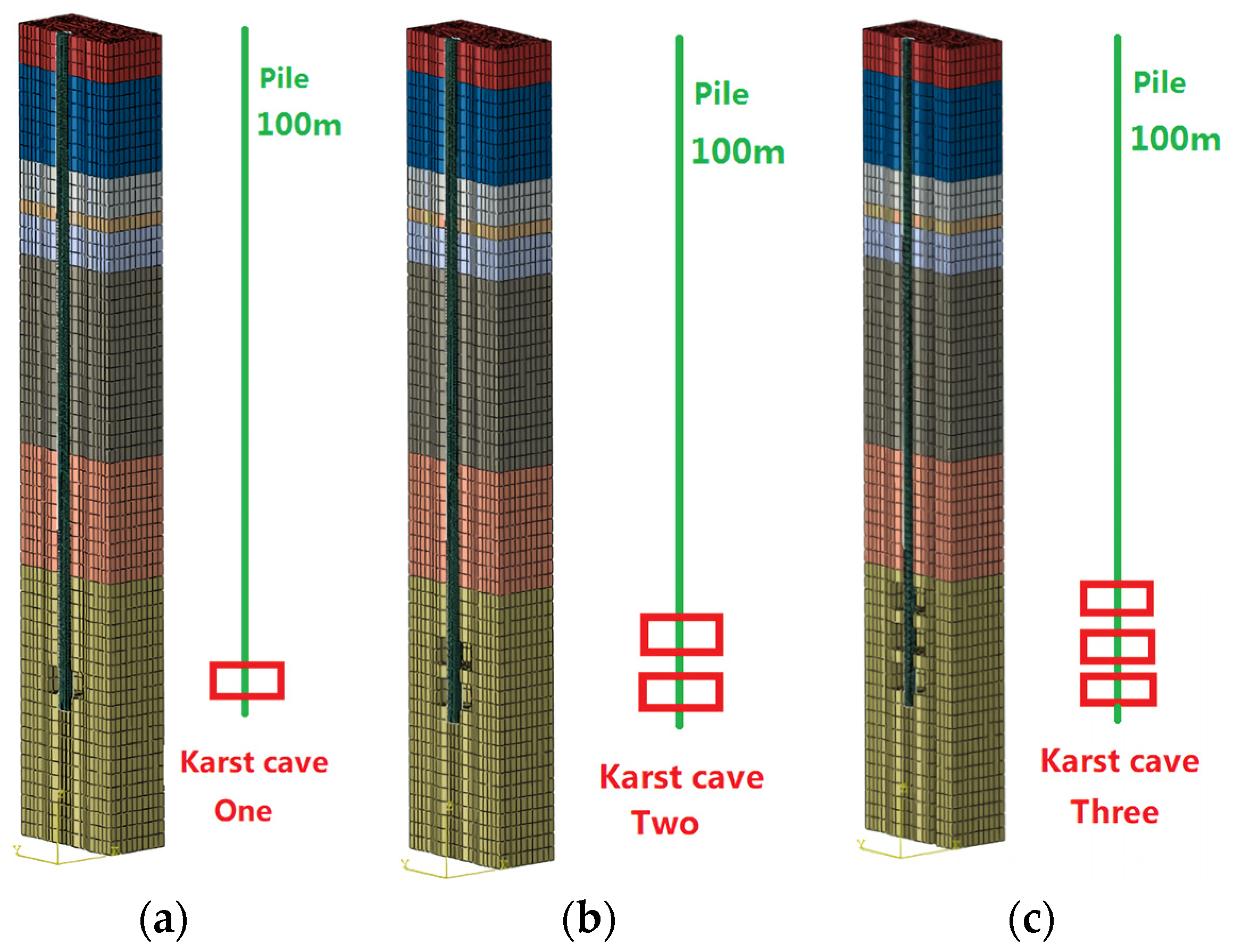
4.1. Analysis of the Rock-Socketed under the Conditions of Beaded Karst Caves

In practical applications, the rock and soil conditions are complex and diverse; thus, there may be multiple karst caves in series in the bedrock. In order to deeply explore the influence of multiple karst caves on pile foundation, three working conditions of single-, double-, and three-beaded karst caves with a height of 4 m were selected for numerical simulation in this section. The schematic diagram of the finite element model is shown in Figure 7. The base elevation of the karst cave at the bottom under different working conditions was 98 m deep. The distribution law of the peak strain of the pile shaft with buried depth under different working conditions is shown in Figure 8.
By analyzing the strain peak value and curve strain law of the abovementioned finite element model with different series of karst caves, at the cohesive soil layer with a buried depth of more than 80 m, the value and distribution law of the pile strain were similar to that of the single-karst cave model. The elastic modulus of the cohesive sand layer around the pile was small and the restraint effect was small, but the soil pile interaction was relatively significant. Therefore, the strain of the pile was large and showed a gradually increasing trend. Under the combined action of vertical load and seismic load, the pile strain increased with the increase of the number of beaded karst caves, which is also because the existence of karst caves reduces the restraint effect of bedrock on the pile. Similar to the pile strain distribution of the single-karst cave model, the pile strain in the model with different numbers of karst caves also showed the distribution law of being large at both ends and small in the middle. Comparing Figure 9c with Figure 4d, when the total height of the karst cave was the same, the calculation result of the maximum strain peak of the pile of the single-karst cave model was similar to that of the three-beaded karst cave model. However, compared with the single-karst cave model, the bedrock between the karst caves in the three-beaded karst cave model had an embedding effect on the pile, which induced the strain distribution of the pile in this area, showing the distribution characteristics of “multi-segment and multi-broken line”.

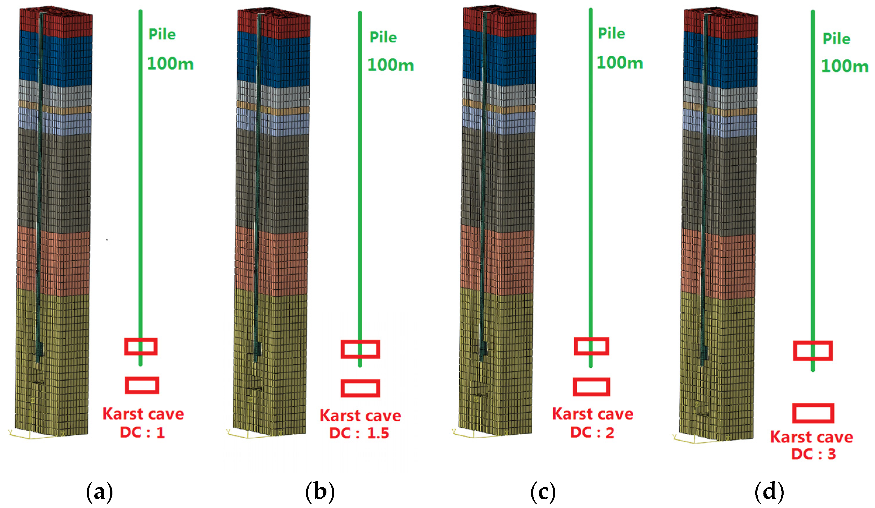
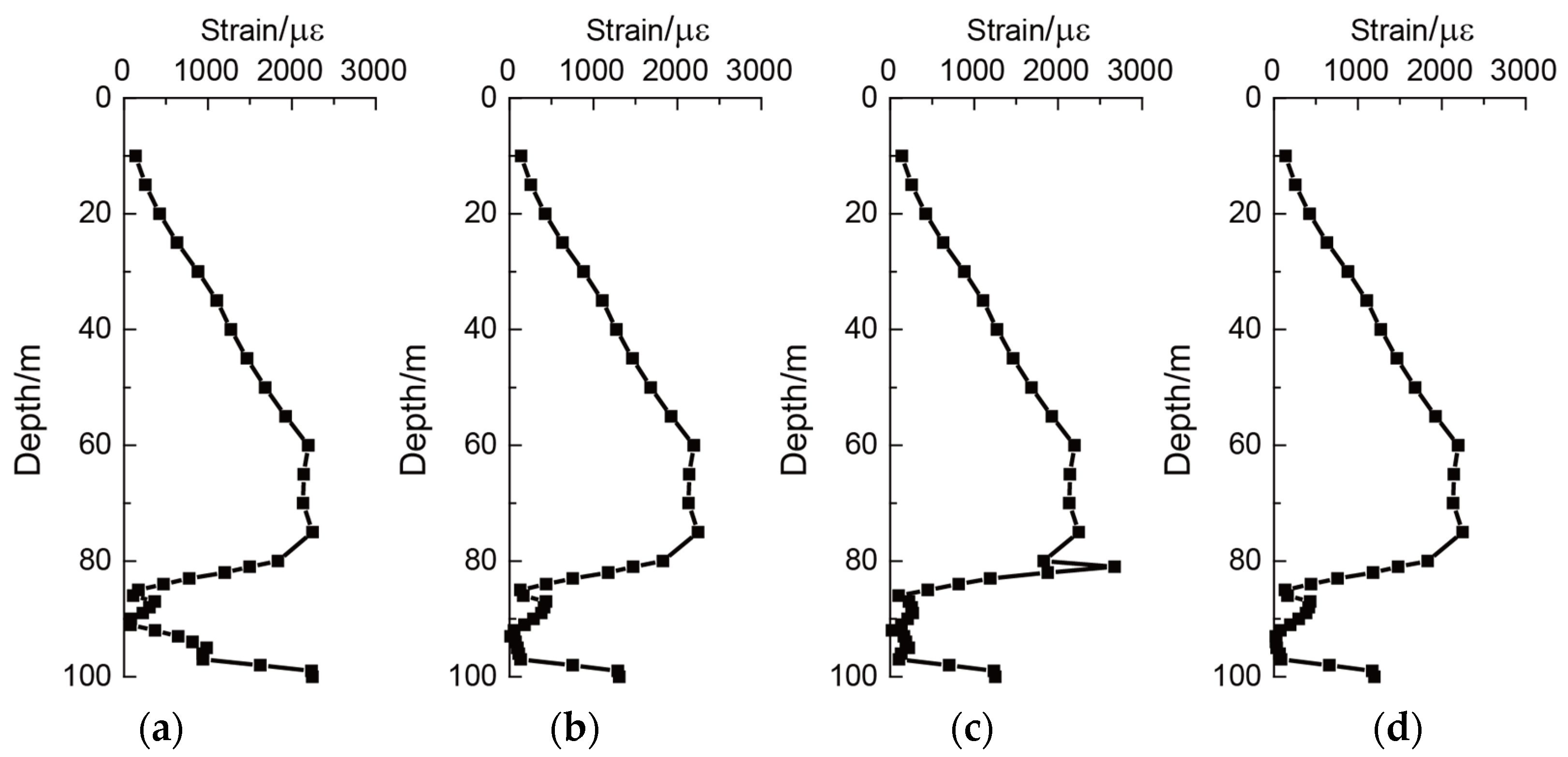
4.2. Analysis of the Rock-Socket under the Conditions of the Beaded Karst Cave and Underlying Karst Cave

In the actual engineering situation, karst caves are always likely to appear at the bottom of the pile string. In this section, karst caves with a height of 4 m and a width of 8 m were selected, which were divided into pile passing karst caves and underlying karst caves. The through pile karst cave was located at the base elevation with a buried depth of 98 m, while the underlying karst cave was located at the buried depth of 106 m, 108 m, 110 m, and 114 m, respectively. In order to study the pile foundation problem under the coexistence of different karst caves, this section introduces a distance coefficient, which is defined as the ratio of the height of the underlying karst cave roof to the bottom plate of the pile passing karst cave to the height of the karst cave to characterize the mutual position relationship of different karst caves. In this section, the distance between the top plate of the underlying karst cave and the bottom plate of the pile passing karst cave was 4 m, 6 m, 8 m, and 12 m, while the distance coefficients (DC) relative to the height of the pile passing karst cave were 1, 1.5, 2, and 3, respectively. The influence of the existence of the underlying karst cave on the strain distribution law of the rock-socketed pile was further explored. The schematic diagram of the finite element model is shown in Figure 9. The distribution law of peak strain of pile shaft with buried depth under different working conditions is shown in Figure 10.
By analyzing the strain peak and curve strain law of the finite element model of the underlying karst cave at different distances, it can be seen that under the action of vertical load and seismic load, the existence of the underlying karst cave reduced the restraint effect of the bedrock at the bottom, resulting in the increase of the peak strain of pile until a certain extent. The distance between the underlying karst cave and the pile is an important parameter that affects the strain of the pile. When the DC of the underlying karst cave is 1, the influence of pile strain decreased with the increase of the relative DC. When the DC of the relative through pile karst cave exceeded 2, the existence of the underlying karst cave had little effect on the pile strain. Under the condition that the distance between the karst cave under the joint influence of the pile passing and the underlying karst cave is small, the existence of the karst cave limited the restraint effect of the bedrock at the bottom. Therefore, it is recommended to strengthen the bedrock between the pile foundation and the karst cave by grouting.

5. Conclusions

In this paper, a finite element numerical simulation combined with a practical major bridge structure rock-socketed pile project was employed considering the effect of vertical load on the rock-socketed pile. The influence of different influencing factors on the peak strain of the pile were analyzed, and the strain distribution laws of the pile under the condition of complex and multiple karst caves were also explored. The seismic responses of the rock-socketed pile can contribute to the seismic reinforcement measures in actual conditions. The main research conclusions are as follows:
(1)
The existence of karst caves in bedrock would significantly affect the strain of the rock-socketed pile. The pile strain at the corresponding position in the karst cave was relatively large. With the increase of the karst cave height and the decrease of the karst cave roof, the restraint effect of the bedrock near the pile gradually decreased and the peak strain of the rock-socketed pile gradually increased.
(2)
The peak strain of the pile would gradually increase with the increase of the number of beaded karst caves under the condition of beaded karst caves. Moreover, due to the restraint of bedrock between karst caves, the pile presented the distribution characteristics of “multi-segment and multi-polyline”.
(3)
In the condition of the underlying karst cave, the existence of the underlying karst cave reduced the restraint effect of the bedrock at the bottom, and made the peak strain of the pile increase to a certain extent. With the increase of the distance coefficients (DC), the influence also decreased. When the DC exceeded 2, the existence of the underlying karst cave had little effect on the pile strain.
(4)
Due to the same viscous sand layer above 80 m, the peak strain distribution of the pile above 80 m buried depth was almost the same under all conditions. The soil properties would have a great influence on the response of the pile.
(5)
According to the seismic response of rock-socketed pile, the pile strain at the location of karst cave was considerable; the mentioned dangerous location of the pile should be appropriately reinforced or reinforced with steel hoops. Under the conditions with pile-through and underlying karst cave, the existence of a karst cave reduced the restraint effect of the bedrock at the bottom; it is necessary to strengthen the bedrock between the pile foundation and the karst cave by grouting.
In the actual engineering, there would be numbers of rock-socketed piles in a large bridge, and the seismic interaction of all the piles would have considerable influences on the seismic responses of the whole soil-pile system. Therefore, the seismic group effect of rock-socketed piles should be further investigated.

Author Contributions

Conceptualization, P.W. and P.Z.; methodology, P.W. and P.Z.; software, D.Q.; validation, W.H.; formal analysis, W.H.; investigation, W.H.; resources, D.Q.; data curation, P.W.; writing—original draft preparation, D.Q.; writing—review and editing, P.W. and P.Z.; visualization, P.W. and P.Z.; supervision, P.W. and P.Z.; project administration, P.W.; funding acquisition, P.W. All authors have read and agreed to the published version of the manuscript.

Funding

This research was funded by [the Natural Science Foundation of Shandong Province] grant number [ZR2021ME238].

Data Availability Statement

The data presented in this study are available on request from the corresponding author. The data are not publicly available due to fund requirements.

Acknowledgments

The authors express their sincerest gratitude for the support. The authors would like to thank John Zhao, Shandong Jianzhu University, for the constructive suggestions on this paper.

Conflicts of Interest

The authors declare no conflict of interest.

References

  1. Yang, S.S.; He, S.; Xie, K.Z.; Li, J. Seismic Damage Analysis and seismic resistance research progress of architectural structures in karst area of China. Seism. Res. 2013, 36, 401–406. [Google Scholar]
  2. Zhang, J. Study on Bearing Mechanism and Stability Evaluation of Pile Foundation in Hidden Karst Cave Area with Inclined Roof. Ph.D. Thesis, Shandong University, Jinan, China, 2019. [Google Scholar]
  3. Feng, M.W. Bearing Mechanism and Experimental Study of Bridge Pile Foundation in Karst Area. Ph.D. Thesis, Hunan University, Changsha, China, 2014. [Google Scholar]
  4. Zhang, Y.J.; Deng, J.Q.; Yang, X.S.; Zhao, M.H.; Wang, G.Y. Stability analysis method of karst pile foundation considering spatial shape of karst cave. Chin. J. Highw. 2019, 32, 37–45. [Google Scholar]
  5. Zeng, W.M. Pseudo-Static Test and Seismic Performance of Slope Rock-Socketed Single Pile with Vertical Load. Master’s Thesis, Chongqing University, Chongqing, China, 2021. [Google Scholar]
  6. Rajeswari, J.S.; Sarkar, R. Seismic behavior of batter pile groups embedded in liquefiable soil. Earthq. Eng. Eng. Vibration 2021, 20, 583–604. [Google Scholar] [CrossRef]
  7. Phung, M.V.; Nguyen, D.T.; Doan, L.T.; Nguyen, D.V.; Duong, T.V. Numerical investigation on static bending and free vibration responses of two-layer variable thickness plates with shear connectors. Iran. J. Sci. Technol. Trans. Mech. Eng. 2022, 46, 1047–1065. [Google Scholar] [CrossRef]
  8. Phung, M.V.; Tam, T.D.; Ke, T.V. Static bending analysis of symmetrical three-layer FGM beam with shear connectors under static load. J. Sci. Tech. 2020, 15, 68–78. [Google Scholar] [CrossRef]
  9. Dung, N.T.; Minh, P.V.; Hung, H.M.; Tien, D.M. The Third-Order Shear Deformation Theory for Modeling the Static Bending and Dynamic Responses of Piezoelectric Bidirectional Functionally Graded Plates. Adv. Mater. Sci. Eng. 2021, 2021, 5520240. [Google Scholar] [CrossRef]
  10. Xu, C.S.; Gao, Y.C.; Chen, S.; Du, X.L.; Dou, P.F. Shaking table test design of liquefaction site pile foundation considering ground motion duration. Earthq. Eng. Eng. Vib. 2017, 37, 51–57. [Google Scholar]
  11. Zhang, R. Numerical simulation of dynamic response of rock-socketed pile foundation under horizontal seismic load. East China Highw. 2016, 3, 29–30. [Google Scholar]
  12. Abuhajar, O.; Naggar, H.E.; Newson, T. Experimental and numerical investigations of the effect of buried box culverts on earthquake excitation. Soil Dyn. Earthq. Eng. 2015, 79, 130–148. [Google Scholar] [CrossRef]
  13. ABAQUS. 6.14 Document; ABAQUS. Inc.: Palo Alto, CA, USA, 2014. [Google Scholar]
  14. Guo, J.; Chen, J.Y.; Bobet, A. Influence of a subway station on the inter-story drift ratio of adjacent surface structures. Tunn. Undergr. Space Technol. 2013, 35, 8–19. [Google Scholar] [CrossRef]
  15. Huang, J.Q.; Du, X.L.; Jin, L.; Zhao, M. Impact of incident angles of P waves on the dynamic responses of long lined tunnel. Earthq. Eng. Struct. Dyn. 2016, 45, 2435–2454. [Google Scholar] [CrossRef]
  16. Liao, Z.P.; Liu, J.B. Elastic wave motion in discrete grids. Earthq. Eng. Eng. Vib. 1986, 6, 1–16. [Google Scholar]
  17. Du, X.L.; Zhao, M. Analysis method for seismic response of arch dams in time domain based on viscous-spring artificial boundary condition. J. Hydraul. Eng. 2006, 37, 1063–1069. [Google Scholar]
  18. Qiu, D.P.; Chen, J.Y.; Xu, Q. Comparative numerical analysis on dynamic effects of underground large scale frame structures under seismic waves. Tunn. Undergr. Space Technol. 2019, 83, 35–50. [Google Scholar] [CrossRef]
Figure 1. Finite element models of the soil and pile. (a) Soil, (b) pile.
Applsci 13 00784 g001
Figure 2. Accelerations and acceleration response spectrums of the Kobe earthquake. (a) Acceleration, (b) acceleration response spectrum.
Applsci 13 00784 g002
Figure 3. Schematic diagram of the finite element model of the rock-socketed piles with different cave heights. (a) Height 4 m, (b) height 8 m, (c) height 12 m, (d) height 16 m.
Applsci 13 00784 g003
Figure 4. The results of the rock-socketed piles with different heights of the karst cave. (a) Height 4 m, (b) height 8 m, (c) height 12 m, (d) height 16 m.
Applsci 13 00784 g004
Figure 5. Schematic diagram of the finite element model of the rock-socketed piles with different cave roof heights. (a) Height 14 m, (b) 10 m, (c) 6 m, and (d) 2 m.
Applsci 13 00784 g005
Figure 6. Results of the rock-socketed piles with different karst cave roof heights. (a) Height 14 m, (b) 10 m, (c) 6 m, and (d) 2 m.
Applsci 13 00784 g006
Figure 7. Schematic diagram of the finite element model of the rock-socketed pile with different karst caves. (a) Single-beaded karst cave, (b) double-beaded karst cave, and (c) three-beaded karst cave.
Applsci 13 00784 g007
Figure 8. Results of the rock-socketed piles with different numbers of karst caves. (a) Single-beaded karst cave, (b) double-beaded karst cave, and (c) three-beaded karst cave.
Applsci 13 00784 g008
Figure 9. Schematic diagram of the finite element model of the rock-socketed pile with different DCs of the karst cave under pile. (a) DC at 1, (b) DC at 1.5, (c) DC at 2, and (d) DC at 3.
Applsci 13 00784 g009
Figure 10. Results of the rock-socketed piles with different DCs of karst caves under pile. (a) DC at 1, (b) DC at 1.5, (c) DC at 2, and (d) DC at 3.
Applsci 13 00784 g010
Table 1. List of symbols in paper.
Symbols Symbols Symbols
c Cohesion r Third stress invariant α n Correction coefficients of the spring in the normal direction
φ Friction angle q Mises equivalent stress α τ Correction coefficients of the spring in the tangent direction
σ 1 First principal stress θ Polar angle G Shear modulus of the medium
σ 3 Third principal stress K n Coefficients of spring in the normal direction ρ Density of the medium
τ Shear stress C n Coefficients of damper in the normal direction R Distance
S s = σ 1 σ 3 / 2 K τ Coefficients of spring in the tangent direction c p Propagation velocities of compression wave
σ m σ m = σ 1 + σ 3 / 2 C τ Coefficients of spring in the tangent direction c s Propagation velocities of shear wave
Table 2. Material parameters of soil and pile.
LayerDensity
(kg/m3)
Elastic Modulus
(MPa)
Friction Angle (°)Cohesion
(kPa)
Thickness (m)
Layer-119507.3910.4306
Layer-218505.608.42914
Layer-319205.689.6366
Layer-420004.6412.3152
Layer-518704.6114.0436
Layer-619207.2729.54328
Layer-719307.7928.83218
Bedrock268014,00044.5140
Pile240030,000
Disclaimer/Publisher’s Note: The statements, opinions and data contained in all publications are solely those of the individual author(s) and contributor(s) and not of MDPI and/or the editor(s). MDPI and/or the editor(s) disclaim responsibility for any injury to people or property resulting from any ideas, methods, instructions or products referred to in the content.

