Abstract
This paper presents a vibration control method for the vibration suppression of a robotic arm. To understand the causes of the vibration in the six-axis manipulator and then eliminate the vibration through an effective control method, the vibration control structure can be divided into two parts. First, variational mode decomposition (VMD) and the Hilbert–Huang transform (HHT) algorithm are integrated to analyze the vibration signal and extract the vibration characteristics. Second, a smooth trajectory planning method is used to eliminate the residual vibration. Then, a feedback controller and iterative learning controller are used for controlling the vibration to stabilize the system while compensating for the torque of the elastic-joint model and repetitive errors caused by the vibration through the repeated operation of the arm. In addition, to improve the iterative learning control (ILC) performance, the integration of VMD and the HHT is used to distinguish useless information. The ILC is able to learn more quickly and compensate for the error caused by the vibration. The proposed VMD-HHT iterative learning control for the elastic joint (VH-ILC-EJ) method, along with a laboratory-developed six-axis degree-of-freedom (6-DOF) robotic arm, has been numerically and experimentally validated for vibration suppression.
1. Introduction
With the rapid development of automation, industrial robots have a broad range of applications. Some robots are equipped with flexible components, such as a harmonic drive, which produces a high reduction ratio and zero backlashes. However, the flexible joint manipulator encounters certain problems, including a reduction in the structural mode damping, an increase in flexibility, and a large amplitude vibration response, all of which seriously affect its positioning accuracy. Nonlinear torsional compliance and hysteresis are associated with harmonic drives. The neural network was used for end-effector force estimation [1]. Zhang proposed a compliance model that captures the harmonic drive nonlinear stiffness of transmissions and hysteresis behavior in modeling a harmonic drive actuator [2]. Spong modeled the elasticity of a joint as a linear torsional spring [3], and Wolfgang analyzed the robustness of nonlinear decoupling for elastic-joint robots [4]. The torque between the motor and the link is considered elastic, and the dynamics extend to the elastic-joint dynamics. The elastic-joint dynamics are consistent with the structure of the flexible robot and efficient for modeling flexible manipulators [5,6,7]. A zero time-delay input shaping with contour-error compensations is applied for the vibration suppression of a multi-axis manipulator with elastic joints [8].
Vibration signals from the manipulator that contain essential information reflect the operation state of the arm. To analyze nonlinear and non-stationary data, Huang proposed the Hilbert–Huang transform (HHT), which uses empirical mode decomposition [9]. Later, Dragomiretskiy utilized a non-recursive variational mode decomposition (VMD) method [10]. The HHT, which decomposes a signal into intrinsic mode functions (IMFs) to obtain instantaneous frequency data, has a broad range of applications, including the frequency analysis of the disturbance torque exerted on a carriage arm in hard drives [11]. Some methods based on the HHT have been proposed, such as evaluating the single-event characteristics of voltage sags in power systems [12] and fault classification in power distribution systems [13]. Unlike the HHT, a recursive mode and mixing phenomenon in EMD, VMD is a non-recursive variational mode decomposition where the modes are extracted concurrently. VMD has been applied in feature trend extraction for the intelligent fault diagnosis of machines [14], and the integration of VMD with the Hilbert transform has been used for automatic power quality event recognition [15]. The HHT decomposed frequency data using VMD instead of the traditional empirical mode decomposition for the high voltage direct current ancillary control of multiple frequency data attacks [16].
Industrial robots commonly perform repetitive tasks, and the iterative learning control (ILC) is well suited. ILC constantly compensates for repetitive errors during the repetitive operation of the manipulator, improving its overall performance. Various ILC schemes have been studied and widely applied in robotics. A dual-stage ILC was applied to robots with joint elasticity to solve tracking control problems [17]. The ILC performs as an add-on feedforward controller on the existing real-time feedback controller to improve the performance of the standalone real-time feedback system. Moreover, ILC was utilized in the motion and force control of deep robotic rolling [18], vibration control, and trajectory tracking control of a robotic arm system with an input constraint [19].
Industrial robots are often used to perform repetitive tasks. Iterative learning control (ILC) is well suited to this case. ILC constantly compensates for repetitive errors during the repetitive operation of the robot arm, in this way improving the performance of the robot arm. Arimoto et al. proposed the concept of ILC for repetitive processes [20]. Various ILC schemes have been studied and widely applied to vibration suppression [17,21,22,23]. ILC can achieve good compensation for repetitive error [24,25], while the non-repetitive part limits the achievable performance of ILC.
Motivated by the need to control and suppress the vibration for a robotic arm, this paper proposes a VMD-HHT iterative learning control for the elastic joint (VH-ILC-EJ) method. This method utilizes ILC and considers the elastic-joint dynamics of a robotic arm with the inputs of the feature extraction of a vibration signal analysis by integrating VMD and the HHT.
The remainder of the paper offers the following:
- -
- A forward elastic-joint dynamics model is formulated, and the recursive Newton–Euler method is utilized to solve the inverse model. The controller design involves elastic-torque feedback and input-based iterative learning control. Integrating the HHT and VMD is used to extract the features of the vibration signals, and the features are fed into the controller for vibration suppression.
- -
- The VH-ILC-EJ method is numerically validated by a simulation of a laboratory-developed six-degree-of-freedom (6-DOF) robotic arm, and the VH-ILC-EJ method is experimentally evaluated via its implementation in the laboratory-developed 6-DOF robotic arm.
2. Control of Robotic Arm with Elastic Joints
Figure 1 illustrates the robotic arm with the joints equipped with harmonic drive actuators. The elastic-joint model in Figure 1a was utilized to analyze the dynamics of a robotic arm that uses the joints of DC motors integrated with the harmonic drives in Figure 1c. The elastic-joint dynamics models the flexible joint by connecting a linear torsional spring between the motor and link. The energy absorbed and released between the mechanisms causes a residual vibration. Figure 1b shows the proposed VH-ILC-EJ method to suppress the residual vibration of the robotic arm. The mode number, V, observed via VMD, inputs into the HHT to generate IMFs. The features extracted from the VMD are fed into the ILC to generate the ILC control input, up. The control input of the VH-ILC-EJ method is determined by adding up and the input of the elastic-torque feedback controller, us.
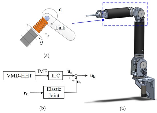
Figure 1.
Illustration of the elastic joint for a robotic arm. (a) Elastic joint. (b) Flowchart of the VH-ILC-EJ method. (c) Robotic arm.
2.1. Elastic-Joint Dynamics Modeling
The forward method models the dynamics of elastic joints using link-side and motor-side equations. The given torques determine the dynamics of the robot. The inverse method applies the recursive Newton–Euler method to obtain the torque from the desired trajectory.
2.1.1. Forward Method Based on the Elastic-Joint Model
The elastic-joint robot dynamics were proposed by Spong in [4] as follows:
Equations (1) and (2) formulate the link-side and motor-side equations of motion. θ and q represent the angular displacement of the motors and links of the robotic arm. M, C, and g denote the inertia matrix, Coriolis and generalized centrifugal forces, and the generalized gravitation forces, respectively. τe represents the elastic torque generated by a linear torsional spring. B and τm denote the inertia matrix and torque of the motor, respectively. Gr is the gear ratio.
2.1.2. Inverse Model Based on Recursive Newton–Euler Method
Assuming that the elastic joint is linear, the elastic torque is expressed as
where K is the linear torsional spring coefficient. In practical application, τe is obtained from the torque sensor installed at the end of the link, θ is acquired by the transmission of the encoder of motor, and K is obtained from the manufacturer. The angular displacement of the link side is determined by (3) and applies to the design of the nonlinear state observer. When q approaches Grθ in (3), the elastic torque is nearly zero. In this situation, the influence of the elastic torque on the link is reduced to suppress the vibration.
Substituting (3) into (2), the following is obtained:
The desired torque of the motor τm can be solved by (4). While and are known, the elastic torque τe and torque of the motor τm are determined by (4). To solve the second derivative of the elastic torque , the jerk and snap are obtained by taking the differential of the acceleration and the acceleration of the angle in forwarding recursion and then substituting the resulting values into the differential of the force and torque in a backward recursion. The differential rules are established [6]. The recursive Newton–Euler method is used to solve the inverse dynamic model of the multi-link flexible robotic arm. τ, e, and are obtained from q and the first- to the fourth-order derivative of q (,,,). Dynamic models of the motor-side dynamics and two-inertia system are determined by (3) and (4), respectively. Since most industrial robots are not equipped with additional sensors or encoders on the link-side motor, the link-side states are estimated using the observation method [18]. The sensors of motors evaluate the link-side angular accelerations
The states are obtained from the sensors on the motor side, including the feedback of the motors’ angular displacement and angular velocity.
2.2. Controller Design
The controller design of the robotic arm involves two parts. The first part is to compensate for the elastic-torque feedback, and the second part uses the input-based iterative learning control algorithm to improve the tracking.
2.2.1. Elastic-Torque Feedback Controller
The input of the elastic-torque feedback controller, us (6a), includes the partial compensation for the motor trajectory error, ut, in (6b) and the elastic torque, ue in (6c).
In compensation for the motor trajectory error, the motor joint angle and angular velocity are used to reduce the tracking error in every operation cycle in (6b), where Ktp and Ktv represent the gain of the angular displacement and the angular velocity error, respectively. τd represents the desired motor torque. θd and are the planned trajectory and its derivative. θ and are obtained from the feedback of the motor encoder. The error between the link and the motor is compensated for by suppressing the elastic torque in the two-inertia systems in (6c), where Kep and Kev represent the gain matrix. q and represent the angular displacement and angular velocity of the link-side output.
2.2.2. Controller Iterative Learning Control Scheme
Figure 2 illustrates a block diagram of the proposed input-based ILC algorithm. The control input, uc,k, updates each iteration instead of updating the reference trajectory.
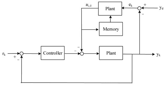
Figure 2.
Block diagram of the input-based ILC.
An acceleration term is added to the proposed input-based ILC to suppress abrupt vibrations:
where Ka represents the gain of the angular acceleration error. Subscript k denotes the kth data. and denote the desired acceleration of the link and the actual acceleration of the kth output, respectively. Further, the past information regarding the input, which contains the interference to which the system was subjected in the past, is added to improve the tracking performance in (8a). α is the parameter that adjusts the ratio between the previous and present input in (8b). λk is a positive number. The function, α, decays as the iteration number, k, increases. When k is larger than λk, α is 0. This property means that when the number of iterations is more than λk, it no longer needs the information obtained from the previous iteration and guarantees the convergence of the ILC algorithm. Figure 3 shows the function of α(k) for various gains λk.
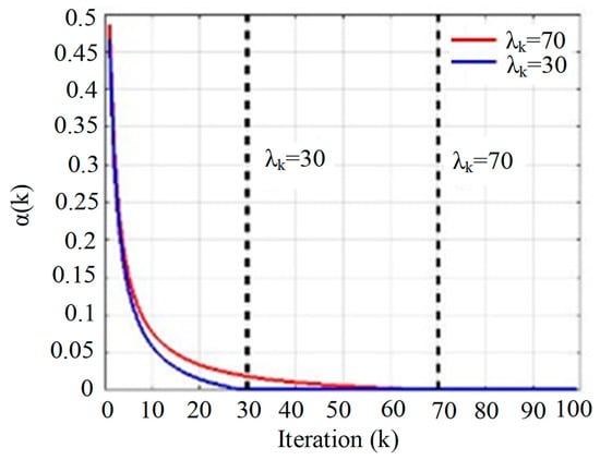
Figure 3.
The parametric effect of λk on α(k).
2.3. Vibration Signal Analysis and Feature Extraction
The vibration signals from the manipulator contain important information about the operation state of the arm. Usually, the manipulator vibrates during motion due to its structure. The vibration information produced during motion can be measured by sensors, such as the accelerometer, and analyzed through the torque signal feedback from the motor side. Therefore, the accelerometer and torque signal contain vibrational signals. The vibrations of the manipulator are low-frequency due to its structure, but some high-frequency noises will influence the measurement. Therefore, it is improper to directly analyze the information from the accelerometer or torque sensors. The HHT and VMD can be used to extract the characteristics of the vibration signal before analysis.
A recursive mode decomposition technique can quickly produce mode mixing problems, resulting in distortion of the IMFs after decomposition and thus leading to hindered analysis. However, the VMD method must determine the mode number, v, required for decomposition in advance. Because the vibration signal is random, it is impossible to determine the number of mode numbers in advance. The proposed method is to observe whether the decomposition is over-decomposed or under-decomposed to judge the number of mode numbers that need to decompose. The VMD-HHT method combines the HHT and VMD to extract the features of mechanical robotic arms and vibration signals for analysis. The procedure of the VMD-HHT analysis method is as follows:
- (1)
- Based on the observation of the mode number using the HHT, the value of the mode number, V, is determined to decompose the IMFs. The HHT method is applied to the accelerometer and torque signals to obtain multiple IMFs.
- (2)
- The IMFs obtained via the decomposition of the accelerometer signal are compared to the torque signal in a pairwise manner. IMFs similar in terms of the time domain signal waveform are identified to determine the two groups of IMFs related to the vibration.
- (3)
- After extracting the IMFs with the vibration components, the marginal spectrum is used to analyze the frequency distribution. If the results of the two are similar, this group of IMFs is related to the vibration of the arm.
In the signal analysis, VMD decomposes the vibration signal into a series of IMFs containing information regarding the vibration signal for characteristic information extraction. Then, the proposed method is applied to calculate the vibration signal and remove trivial information for quick compensation for the error caused by the vibration. However, the number of modes must be determined before utilizing the VMD algorithm. If the value of the preset mode number is less than the mode number of the original signal, the unique frequency component of the original signal is lost. When the preset value of the mode number is greater than the original mode number of the signal, the decomposed high frequency is very close. Therefore, the proximity of the center frequencies obtained by the decomposition is used to obtain the proper mode number for decomposition.
A search method to automatically determine the appropriate mode number is listed in Algorithm 1. Correctly decomposed center frequencies are spaced apart by a certain distance. This distance is defined as the proximity of the two center frequencies:
where HV,m represents the mth center frequency when the mode number for decomposition is V. HV+1,n represents the nth center frequency for decomposition when the mode number is V + 1, and dV,m,n represents the proximity of the mth center frequency when the mode number is V and the nth center frequency when the mode number is V + 1. First, the center frequency when V = 1 is used as a reference. When the calculated dV,m,n is larger than the preset threshold, dth, the reference is reset as the center frequency of HV+1,n, and vice versa. The distance of separation of the center frequencies is found by searching. The number of center frequencies is the appropriate number of modes.
| Algorithm 1. Automatic choice of a suitable mode number |
| Find V () 1: For V=1 to V=6 2: Calculate VMD and obtain the center frequency of different mode numbers after decomposition. 3: Initialize threshold d, baseline=H1,1 4: For V=1 to V=6 5: For m=1 to size (V) 6: For n=1 to size (V+1) 7: Calculate dV,m,n 8: If min(dV,m,n) > d 9: Baseline=H1,1, HV+1,n 10: Else 11: Continue 12: Calculate the size of the baseline 13: Return V |
2.4. Integrating the ILC-EJ Controller with the VMD-HHT
The vibration signal features are extracted via the VMD-HHT and fed into the ILC-EJ controller for vibration suppression. The proposed VH-ILC-EJ method, which integrates the VMD-HHT with an ILC-EJ controller, involves three steps:
Step 1: Separate the error signal via VMD for every iteration. Use the algorithm to choose the appropriate mode number for decomposition.
Step 2: Filter out useless information and allow the ILC-EJ controller to learn from the error signals caused by the vibration.
Step 3: In each iteration, the error signal and the calculated root mean square (RMS) error of each IMF are decomposed. The error signal is separated if the RMS error continues to increase.
Figure 4 shows the flowchart of the proposed VH-ILC-EJ controller, divided into two parts of the vibration signal analysis and vibration control strategies for the vibration suppression of a 6-DOF manipulator.
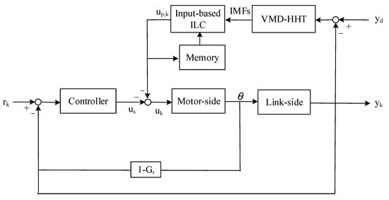
Figure 4.
Block diagram of the input-based iterative learning control.
3. Numerical Validation
The proposed VH-ILC-EJ controller and its effects for controlling a robotic arm with vibration suppression are illustrated numerically and validated by an example of vibration suppression for a laboratory-developed 6-DOF robotic arm in Figure 1b. The mechanical parameters of the robotic arm and the control parameters are listed in Table 1 and Table 2, respectively.

Table 1.
Dynamic parameters of the 6-DOF robotic arm.
Table 2.
Simulated control parameters.
The common motor feedback control has good tracking performance in the simulated environment. Still, the vibration caused by the structure at the endpoint will cause position error, as shown in Figure 5. The solid line is the output of the link side, and the dotted line is the output of the motor side. Figure 5 shows the simulation results of applying the elastic-joint feedback controller to manipulate a 6-DOF robotic arm on the desired trajectory. The vibration caused by the structure at the endpoint causes a position error.
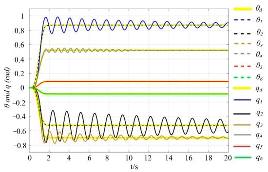
Figure 5.
Motor- and link-side angular displacements with an elastic-torque feedback controller. (solid line: link side, dotted line: motor side).
Figure 6 shows a simulation using the proposed VH-ILC-EJ controller at the 400th iteration. The results show that most of the vibration at the link-side end is suppressed, but some residual vibrations at the fixed point of the link-side arm exist after compensating for the elastic torque. However, the residual vibration is eliminated by using the ILC repeatedly.
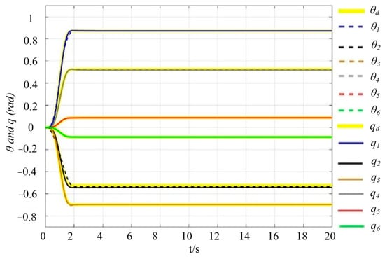
Figure 6.
Motor- and link-side angular displacements using the VH-ILC-ET method. (solid line: link side, dotted line: motor side).
The effects of using the previous information are shown in Figure 7. The simulation results show that the convergence rate increases and the tracking errors are reduced after using the previous information.
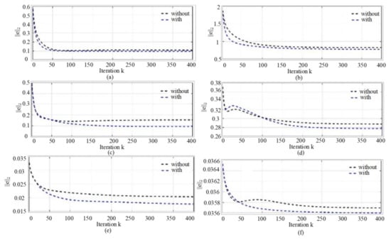
Figure 7.
Comparison of acceleration-type ILC without and with past information. (Blue: with, Black: without) (a) Joint 1. (b) Joint 2. (c) Joint 3. (d) Joint 4. (e) Joint 5. (f) Joint 6.
After 400 iterations, a new input is produced to effectively suppress the residual vibration, so there is no residual vibration on the six-axis of the manipulator at the point of arrival. The position 2 norm error is shown in Figure 6. Using the previous information, a new input is produced to suppress the residual vibration effectively. After using the previous information, the rate of convergence increases, and the tracking error is reduced. At the same time, the input changes in the initial iteration are also relatively stable. In this simulation, only the information from the previous iteration was added, and a significant effect was obtained. If more past information is added, the effect should be better, but the learning gain of ILC needs to be re-adjusted to achieve the best performance. The statistics data of input-based ILC is summarized in Table 3.
Table 3.
Maximum tracking error and L2 norm of the error of an input-based ILC in simulation.
4. Experimental Results
Two experiments were conducted to validate the proposed VH-ILC-EJ controller, the first of which analyzed the effect of the vibration of each joint on the end-effector and the second of which implemented the proposed VH-ILC-EJ controller on the laboratory-developed 6-DOF robotic arm.
4.1. A Single Joint Vibration Signal Analysis
Before the vibration suppression experiments, the effect of the vibration of each joint on the end-effector was analyzed first. The experimental steps are as follows:
Step 1. Depending on the joint limit of each joint, each joint is quickly positive and reversed at a certain angle. Each joint rotates forward and reverses three times.
Step 2. Through a visual judgment and the acceleration of the IMU sensor installed at the endpoint, it is judged whether the arm quickly reaches the fixed point and has residual vibration.
The vibration signal analysis of a single joint involves two steps. As shown in Figure 8a, the inertial measurement unit (IMU) sensor is installed at the joint for measuring the acceleration data to observe the converge rate and vibrations when each joint rotates in the counterclockwise (CCW) and clockwise (CW) direction three times. Figure 8b–g and Figure 9a–f show the measuring acceleration data when the joints rotate 70, 55, 70, 35, 50, and 40 degrees in the CCW and CW direction, respectively. The experimental results show that the first three joints have a more significant residual vibration, while the last three have a trivial residual vibration. Only the vibration signals of the first three joints need to be analyzed and extracted.
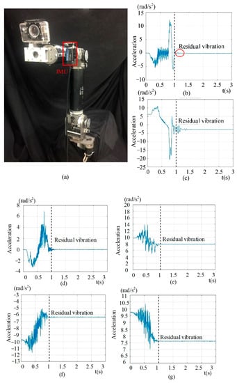
Figure 8.
Experimental setup and data. (a) The installed IMU sensor is installed in joint 5. (b–g): Acceleration data for joints 1 to 6 rotated in the CCW direction. ((b): joint 1, (c): joint 2, (d): joint 3, (e): joint 4, (f): joint 5, (g): joint 6).
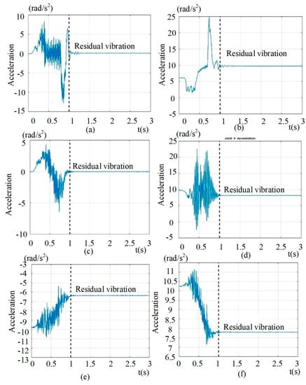
Figure 9.
Experimental acceleration data for joints 1 to 6 rotate in the CW direction. (a) Joint 1. (b) Joint 2. (c) Joint 3. (d) Joint 4. (e) Joint 5. (f) Joint 6.
Joints one, two, and three have some residual vibration when they reach the fixed point rapidly, while there is no residual vibration in joints four, five, and six at the point of arrival. It can be concluded that the vibration of the six-axis robot arm mainly comes from the vibration of joints one, two, and three, so in the subsequent control, the vibration of the robot arm can be restrained by mainly suppressing the vibration of these three joints. Joints four, five, and six can be treated as rigid bodies. Therefore, in the subsequent vibration signal analysis, only joints one, two, and three are analyzed, and valid information is extracted. After the VMD method, the problems of mode mixing and over-decomposition are overcome, which makes the extraction of vibration features more accurate. It can be seen from the results that the acceleration and torque signals in joint one have corresponding frequency components, which can be considered to be caused by the manipulator reaching a fixed point. The results are shown in Table 4. Frequency features extract the IMF with vibration signals. These can be used in each iteration to remove useless information and increase learning speed.
Table 4.
Vibration characteristics of the VMD-HHT analysis of joint 1.
The VMD method extracts the vibration features and makes the extraction of the vibration features more accurate. Figure 10a,b shows the VMD of the torque and acceleration signals. The simulation results show that the acceleration and torque signals have similar trends. Figure 10c,d shows the acceleration and torque spectrum of IMF 1 and 2, respectively. The vibration characteristics of an example VMD-HHT for the first joint are listed in Table 4. The features in each iteration are used to remove useless information and increase the learning speed.
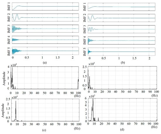
Figure 10.
Signals of joint 1. (a) VMD of the torque signal. (b) VMD of the acceleration signal. (c) Acceleration marginal spectrum of IMF 1 and 2. (d) Torque marginal spectrum of IMF 1 and 2.
4.2. Multiple Joint Vibration Suppression
Figure 11 demonstrates the experimental results of applying the VH-ILC-EJ method to the laboratory-developed 6-DOF robotic arm with Kp = 1.2, Kd = 0.3, Ka = 1, and λk = 10. Figure 11a shows two screenshots of a scenario where the robotic arm moves a cup filled with liquid. Figure 11b,c are screenshots of the movements of iterations 1 and 20 for the experiment to validate the effects of VMD-HHT. Iteration 1, considered the ILC, is not implemented, while iteration 20, as the VH-ILC-ET method, is implemented. The experimental results show that the liquid in the container is more stable when implementing the VH-ILC-EJ method, demonstrating a vibration suppression ability. Figure 11d,e are screenshots of the movements of iterations 1 and 20 for the experiment to validate the effects of ILC. Iteration 1, considered the ILC, is not implemented, while iteration 20, as the ILC is implemented. The liquid in the container is more stable when the ILC is implemented. From Figure 11c,e, the VH-ILC-EJ method performs better than ILC-EJ method.
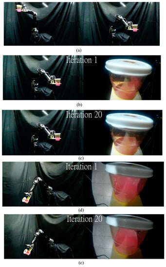
Figure 11.
Experiments of multiple joint vibration suppression. (a) Screenshots of the movement. (b) Without ILC-VMD-HHT. (c) With ILC-VMD-HHT. (d) Without ILC. (e) With ILC.
Figure 12a,b shows the link-side angular displacements of the first and second joints, and Figure 12c shows the acceleration data of the second joint with and without implementing ILC. In multi-joint experiments, the vibrations of the first joint are obvious. Similarly, in the iterative process, the error caused by vibration gradually decreases, and the convergence rate of ILC-VMD-HHT is faster than that of ILC. Because there is no obvious vibration in the measurement of second joint, the performance of vibration suppression from the acceleration in the relevant direction is discussed. Similarly, in the iterative process, the error caused by vibration gradually decreases, and the convergence rate of ILC-VMD-HHT is faster than that of ILC. Because there is no obvious vibration in the measurement of the second joint, we discuss the performance of vibration suppression from the acceleration in the relevant direction.
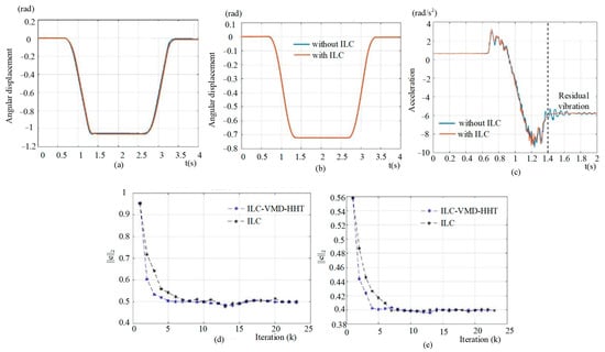
Figure 12.
Effects of ILC and VDM-HHT. (a) Link-side angular displacement of the first joint. (b) Link-side angular displacement of the second joint. (c) Acceleration of the second joint. (d) L2 norm of the error of the first joint. (e) L2 norm of the error for the second joint.
The two curves coincide in Figure 12b. The angular displacements with and without ILC are close. Therefore, the vibration suppression performance from the acceleration in the relevant direction is discussed in Figure 12c. The result shows that the residual vibration still exists at the fixed position. The statistics data for the maximum and 2-norm errors at k = 1 and k = 20 are summarized in Table 4. The experimental results validate the ILC for vibration suppression. Figure 12c,d compares the L2 norm of the error plots for each iteration with and without the VMD-HHT. The experimental results show that the VH-ILC-EJ controller has a small L2 norm error and converges faster than without the application of the VMH-HHT. The maximum and L2 norm errors are listed in Table 5. The results show that the ILC reduces the maximum and L2 norm errors. After ILC-VMD-HHT is applied, the residual vibration is suppressed. As the number of iterations increases, the error and vibration of the actual output of the link side are reduced. Therefore, the proposed control method can also be applied to multi-joint vibration control.
Table 5.
Maximum tracking error and L2 norm of the error of an input-based ILC in experiments.
5. Conclusions
In this paper, two topics are emphasized. One is the vibration signal analysis, and the other is vibration suppression. Elastic-joint dynamics is introduced to understand the reason for the vibration of the six-axis manipulator and eliminate the vibration through an effective control method. Vibration usually occurs when the arm moves rapidly to a fixed point, and the vibration signal contains a wealth of information. A method of VMD-HHT is proposed to analyze the vibration signals and provide effective information for subsequent vibration control to extract useful information and vibration features from vibration signals. Smooth trajectory planning can suppress part of the residual vibration caused by the system. According to the algorithm of elastic-joint dynamics, a smooth trajectory planning method is first used to eliminate the residual vibration, and then the feedback controller and iterative learning controller are used to control the vibration. In addition, information from past learning is added to the traditional ILC controller, and the method of ILC-VMD is proposed, which uses a signal processing method to separate useless information so that the ILC can learn more quickly how to compensate for the error caused by vibration. Finally, the proposed vibration control algorithm is verified by simulations and experiments, and the results are satisfactory.
A VH-ILC-EJ controller has been presented for the vibration suppression of a robotic arm. The VMD-HHT method extracts the vibration signal features and feeds the information into the ILC-EJ controller. As demonstrated numerically, the VH-ILC-ET method has better vibration suppression than when only considering the elastic-joint dynamics. Moreover, the VH-ILC-ET method is applied in a laboratory-developed 6-DOF robotic arm. The results show that the ILC method is valid for vibration suppression, and the VMD-HHT improves the error’s convergence rates and L2 norm. Overall, the VH-ILC-EJ method is effective in the vibration suppression of a robotic arm. In the future, some new methods will be applied to the robotic arm for vibration suppression.
Author Contributions
Conceptualization, H.-P.H.; methodology, H.-P.H. and J.-L.L.; software, J.-L.L.; validation, J.-L.L.; formal analysis, J.-L.L.; investigation, J.-L.L.; resources, H.-P.H. and C.-Y.L.; data curation, J.-L.L. and C.-Y.L.; writing—original draft preparation, J.-L.L.; writing—review and editing, C.-Y.L.; visualization, J.-L.L.; supervision, H.-P.H.; project administration, H.-P.H.; funding acquisition, H.-P.H. All authors have read and agreed to the published version of the manuscript.
Funding
This work was supported in part by the National Science and Technology Council, Taiwan, under grant number 110-2221-E-002-110-MY3 and in part by Syntec Technology Co., Ltd., under Grant TLIR-S200.
Institutional Review Board Statement
Not applicable.
Informed Consent Statement
Not applicable.
Data Availability Statement
Not applicable.
Conflicts of Interest
The authors declare no conflict of interest.
References
- Liu, X.; Zhao, F.; Ge, S.S.; Wu, Y.Q.; Mei, X.S. End-effector force estimation for flexible-joint robots with global friction approximation using neural networks. IEEE Trans. Ind. Informat. 2019, 15, 1730–1741. [Google Scholar] [CrossRef]
- Zhang, H.W.; Ahmad, S.; Liu, G.J. Modeling of torsional compliance and hysteresis behaviors in harmonic drive. IEEE/ASME Trans. Mechatron. 2015, 20, 178–185. [Google Scholar] [CrossRef]
- Spong, M.W. Modeling and control of elastic joint robots. J. Dyn. Syst. Meas. Control. 1987, 109, 310–318. [Google Scholar] [CrossRef]
- Grimmm, W.M. Robustness analysis of nonlinear decoupling for elastic-joint robots. IEEE Trans. Robot. Automat. 1990, 6, 373–377. [Google Scholar] [CrossRef]
- Buondonno, G.; Luca, A.D. A recursive Newton-Euler algorithm for robots with elastic joints and its application to control. In Proceedings of the IEEE International Conference on Intelligent Robots and Systems, Hamburg, Germany, 28 September–2 October 2015. [Google Scholar]
- Damaren, C.J. Approximate inverse dynamics and passive feedback for flexible manipulators with large payloads. IEEE Trans. Robot. Automat. 1996, 12, 131–138. [Google Scholar] [CrossRef]
- Hopler, R.; Thummel, M. Symbolic computation of the inverse dynamics of elastic joint robots. In Proceedings of the 2004 IEEE International Conference on Robotics and Automation, New Orleans, LA, USA, 26 April–1 May 2004. [Google Scholar]
- Lin, Y.-Y.; Kang, Z.-H.; Ting, H.-Y.; Huang, H.-P. Vibration suppression of a 6-DOF robot manipulator based on multi-mode robust input shaping. Int. J. iRobotics 2018, 1, 35–46. [Google Scholar]
- Huang, N.E.; Shen, Z.; Long, S.R.; Wu, M.C.; Shih, H.H.; Zheng, Q.; Yen, N.C.; Tung, C.C.; Liu, H.H. The empirical mode decomposition and the Hilbert spectrum for nonlinear and non-stationary time series analysis. R. Soc. 1998, 454, 903–995. [Google Scholar] [CrossRef]
- Dragomiretskiy, K.; Zosso, D. Variational Mode Decomposition. IEEE Trans. Signal Process. 2014, 62, 531–544. [Google Scholar] [CrossRef]
- Koganeazwa, K.; Tsuda, S.; Tani, H.; Lu, R.G.; Tagawa, N. Frequency analysis of disturbance torque exerted on a carriage arm in hard disk drives using Hilbert-Huang transform. IEEE Trans. Magn. 2018, 54, 3100906. [Google Scholar]
- Hasan, S.; Muttaqi, K.M.; Sutanto, D. Application of the automatic segmented Hibert Huang transform method for the evaluation of the single-event characteristics of voltage sags in power systems. IEEE Trans. Power Syst. 2021, 57, 1882–1891. [Google Scholar]
- Guo, M.-G.; Yang, N.C.; Chen, W.-F. Deep learning-based fault classification using Hilbert-Huang transform and Convolutional Neural Network in power distribution systems. IEEE Sensor J. 2019, 19, 6905–6913. [Google Scholar] [CrossRef]
- Wang, Y.X.; Wei, Z.X.; Yang, J.W. Feature trend extraction and adaptive density peaks search for intelligent fault diagnosis of machines. IEEE Trans. Ind. Informat. 2019, 15, 105–111. [Google Scholar] [CrossRef]
- Sahani, M.; Dash, P.K. Automatic power quality events recognition using modes decomposition based online p-norm adaptive extreme learning machine. IEEE Trans. Ind. Informat. 2020, 16, 4355–4364. [Google Scholar] [CrossRef]
- Qiu, W.; Sun, K.Q.; Yao, W.X.; Wang, W.K.; Tang, Q.; Liu, Y.L. Hybrid data-driven based HVdc ancillary control for multiple frequency data attacks. IEEE Trans. Ind. Informat. 2021, 17, 8035–8045. [Google Scholar] [CrossRef]
- Chen, W.J.; Tomizuka, M. Dual-stage iterative learning control for MIMO mismatched system with application to robots with joint elasticity. IEEE Trans. on Cont. Syst. Technol. 2014, 22, 1350–1361. [Google Scholar]
- Chen, S.Y.; Wang, Z.G.; Chakraborty, A.; Klecka, M.; Saunders, G.; Wen, J. Robotic deep rolling with iterative learning motion and force control. IEEE Trans. Robot. Auto. Lett. 2020, 5, 5581–5588. [Google Scholar] [CrossRef]
- Meng, T.T.; He, W. Iterative learning control of a robotic arm experiment platform with input constraint. IEEE Trans. Electron. 2018, 65, 664–672. [Google Scholar] [CrossRef]
- Arimoto, S.; Kawamura, S.; Miyazaki, F. Bettering Operation of Robots by Learning. J. Robot. Syst. 1984, 1, 123–140. [Google Scholar] [CrossRef]
- Gunnarsson, S.; Norrl, M.; Rahic, E.; Ozbek, M. Iterative Learning Control of a Flexible Robot Arm Using Accelerometers Department of Electrical Engineering. In Proceedings of the 2004 IEEE International Conference on Control Applications, Taipei, Taiwan, 2–4 September 2004; pp. 1012–1016. [Google Scholar]
- Gunnarsson, S.; Norrlöf, M.; Rahic, E.; Özbek, M. On the Use of Accelerometers in Iterative Learning Control of a Flexible Robot Arm. Int. J. Control. 2007, 80, 363–373. [Google Scholar] [CrossRef]
- Tsai, C.; Chen, W.; Yun, D.; Tomizuka, M. Iterative Learning Control for Vibration Reduction in Industrial Robots with Link Flexibility. In Proceedings of the 2013 American Control Conference, Washington, DC, USA, 17–19 June 2013; pp. 5195–5200. [Google Scholar]
- Li, X.; Tian, S.; Ai, W. Active Disturbance Rejection Based Iterative Learning Control. In Proceedings of the 28th Chinese Control and Decision Conference, Yinchuan, China, 28–30 May 2016; pp. 6645–6650. [Google Scholar]
- Sun, J.; Li, S.; Yang, J. Iterative Learning Control with Extended State Observer for Iteration-Varying Disturbance Rejection. In Proceedings of the 11th World Congress on Intelligent Control and Automation Conference, Shenyang, China, 29 June–4 July 2014; pp. 1148–1153. [Google Scholar]


Disclaimer/Publisher’s Note: The statements, opinions and data contained in all publications are solely those of the individual author(s) and contributor(s) and not of MDPI and/or the editor(s). MDPI and/or the editor(s) disclaim responsibility for any injury to people or property resulting from any ideas, methods, instructions or products referred to in the content. |
© 2023 by the authors. Licensee MDPI, Basel, Switzerland. This article is an open access article distributed under the terms and conditions of the Creative Commons Attribution (CC BY) license (https://creativecommons.org/licenses/by/4.0/).