Abstract
Slipping detection and avoidance are key issues in dexterous robotic manipulation. The capability of robots to grasp and manipulate objects of common use can be greatly enhanced by endowing these robots with force/tactile sensors on their fingertips. Object slipping can be caused by both tangential and torsional loads when the grip force is too low. Contact force and moment measurements are required to counteract such loads and avoid slippage by controlling the grip force. In this paper, we use the SUNTouch force/tactile sensor, which provides the robotic control system with reliable measurements of both normal and tangential contact force components together with the torsional moment. By exploiting the limit surface concept and the LuGre friction model, we build a model of the object/fingertip planar sliding. This model is the basis of a nonlinear observer that estimates the sliding velocity and the friction state variable from the measured contact force and torsional moment. The slipping control system uses the estimated friction state to detect the slipping event and the estimated sliding velocity to control the grasp force. The control modality is twofold: the first one is aimed at avoiding object slip, while the second one allows the object to perform a controlled pivoting about the grasping axis. Experiments show that the robot is able to safely manipulate objects that require grasping forces in a large range, from N to N. This level of manipulation autonomy is attained by a suitably identified dynamic model that overcomes the limited generalization capability of existing learning-based approaches in the general roto-translational slip control.
1. Introduction
Humans can grasp and manipulate a variety of objects with dexterity and safety without knowing a priori their physical properties by perceiving the motion of the object upon contact with the fingertips by means of the sense of touch [1]. On the basis of tactile perception, they control the magnitude of the friction force and torque by acting on the grasp force, which the fingertips exert on the object, thereby avoiding grasp failure. Thus, tactile sensing is of paramount importance for humans to interact with the environment. In the last two decades, many designs of tactile sensors have been proposed in the scientific literature by robotics researchers with the aim of mimicking the human sense of touch. Comprehensive reviews of tactile sensing systems for dexterous robotic hands can be found in [2,3]. The proposed solutions are based on two alternative concepts: sensors based on an array of independent contacts or tactile receptors that easily allow for the identification of contact location and sensors based on a continuous deformable medium between the contact and the receptors, which allows a few receptors to interpolate the information among them. The latter are more frequently used to measure contact force intensity or magnitude. Both sensor principles may be supported by different transduction technologies, e.g., resistive, capacitive and magnetic, which can be selected depending on their costs, weights, integration levels, and dimensions. The perception of the torsional moment is a key requirement to select the appropriate tactile sensor to securely grasp an object when it is subject not only to force but also to moment loads. Only a few sensors are capable of measuring the full 6-D wrench; moreover, sensors that are also able to measure torque, e.g., the 6-axis version by Optoforce, use an array of 3-D sensors coupled with a rigid surface that limits the frictional torque that the fingertip can apply to the grasped object. Recently, the GelSight visuotactile sensor, which uses a vision system to translate the deformation of the gel layer caused by the contact with the environment into tactile information [4,5] has been proposed to estimate shear force and contact geometry. A review of visuotactile sensors with an emphasis on GelSight can be found in [6]. In this paper, we use the SUNTouch force/tactile sensor [7,8] developed in our robotics lab. The SUNTouch force/tactile sensor has been demonstrated to be able to provide the grasp controller with accurate measurements of the 6-D contact wrench [9].
Mimicking human ability, slip detection, slipping avoidance and controlled sliding are key facets of making robots capable of grasping and manipulating objects. This means that the robot should be able to detect the incipient grasp failure and control the grasp force to avoid it without damaging the grasped object, or, to change the object/fingertip relative position, to execute controlled sliding of the fingertips without losing contact with the object. Several methods of slip detection have been proposed in the last decade [10]. The approaches can be classified as model-based and model-free approaches. In [11], using the BioTac sensor and resorting to the friction cone concept, the authors compared various slip detection methods. However, slipping detection algorithms based on the friction cone concept fail when a torsional load acts on the grasped object. In [9], the authors presented a model-based approach to slipping detection and avoidance in the presence of both shear and torsional load by resorting to the concept of the limit surface [12]. Model-free approaches, the prevailing trend in recent years, refer to learning-based slip detection methods, mostly based on the use of visuotactile sensors such as GelSight and TacTip. In [13,14], the authors proposed a slip classification framework by resorting to a convolutional long short-term memory network. In [15], the authors, by endowing a three-fingered hand with the TacTip integrated optical tactile sensor, present a method to perform slip detection based on a support-vector machine (SVM).
The decision to adopt a model-based approach here is related to the difficulty of current data-driven methods for robotic slipping detection and avoidance to generalize to manipulated objects made of different types of materials and surface conditions. A re-training of the learning-based strategy is still required for such a class of solutions, especially when surface conditions change due to environmental variability, e.g., moisture or temperature. On the contrary, the superior generalization capabilities of the model-based approach appear to be still attractive to attain a high level of autonomy of the robotic system. Moreover, in all the model-free approaches, after detecting a slip, the reaction designed to stabilize the grasp is of a heuristic type, which means increasing the grasp force until the object stops sliding; the selection of an increasing force of the grasp force should be a trade-off between the desired speed to stop slipping and the caution needed to not damage the object. Differently from the method used in [16] to compute the grasp force to avoid slip, here, the control algorithm, owing to the nonlinear observer, distinguishes the static friction contribution from the viscous one, thus leading to the true minimum amount of grasp force necessary to compensate for the external load and avoid slippage. A recent work proposing this sort of approach is [17], where the slip event was predicted by a classifier based on random forests and the proposed grasp force controller does not compensate for rotational slips.
In this paper, we do not follow the learning-based prevailing trend, but following the approach already presented in [9,16], we present a revisited model-based approach to slip detection/avoidance and controlled sliding. General in-hand manipulation tasks involve both translational and rotational motion; thus, it is necessary to model the relationship between the friction force and torque and the sliding motion. The approach adopted to describe such a relationship, assuming that the contact is planar, is the limit surface concept (LS) [12,18], which relates the sliding motion, described as a rotational motion about the instantaneous center of rotation (CoR), to the maximum friction force and torque as functions of the normal force. The LS concept is a generalization of the Coulomb friction cone concept when friction torsional torque is involved in the soft contact. In order to perceive the object’s motion upon contact with the fingertips using only a force/tactile sensor, it is necessary to estimate the relative velocity between the object and the fingertips. In [19], we introduced a nonlinear observer based on the celebrated LuGre dynamic friction model [20,21] extended to the case of rotational sliding about the CoR. Such a model describes the friction as a pure friction torque with respect to the CoR. The maximum friction torque is provided by the limit surface method. The dynamic model requires the knowledge of the CoR position estimated by using the measurement of the dry friction provided by the force/tactile sensor at the fingertips. The nonlinear observer in [19] has been used in [22] to estimate the sliding velocity with the aim of avoiding object slipping and in [16], where a generalization of the LS method has been proposed by considering not only the effects of the dry friction but also the effects of the viscous one. An additional advantage of the adoption of nonlinear dynamics to model the transition from a no-slip to a slip condition is its numerical stability compared to traditional threshold-based approaches also adopted in tribology, such as in [23].
With the objective of controlling a robot that should be able to grasp and manipulate objects of unknown weight and made of different materials, in this paper, we propose a revisited version of the nonlinear observer to estimate the relative velocity, which also considers the viscous damping depending on the motion of the micro-asperities in contact during the sliding. Introducing this viscous term avoids physically inconsistent oscillations of the internal friction state variable. Although such oscillations do not macroscopically affect the sliding velocity dynamics, as the dynamics of the friction state variable are very fast, they can affect the controlled grasp force if this variable is involved in the control algorithm. We use the friction state variable estimated by the nonlinear observer to detect the slip by means of an indicator, which involves such a state variable and the maximum friction torque provided by the LS with the estimated COR. Then, we design a control scheme, which regulates the estimated sliding velocity to zero if the slipping avoidance modality is selected; alternatively, it allows controlled sliding, which can be rotational, e.g., object pivoting, or linear depending on the estimated COR position. Several experiments will be illustrated in the experiment section to show the effectiveness of the proposed planar sliding model and the proposed grasp control strategy.
2. Contact Modeling
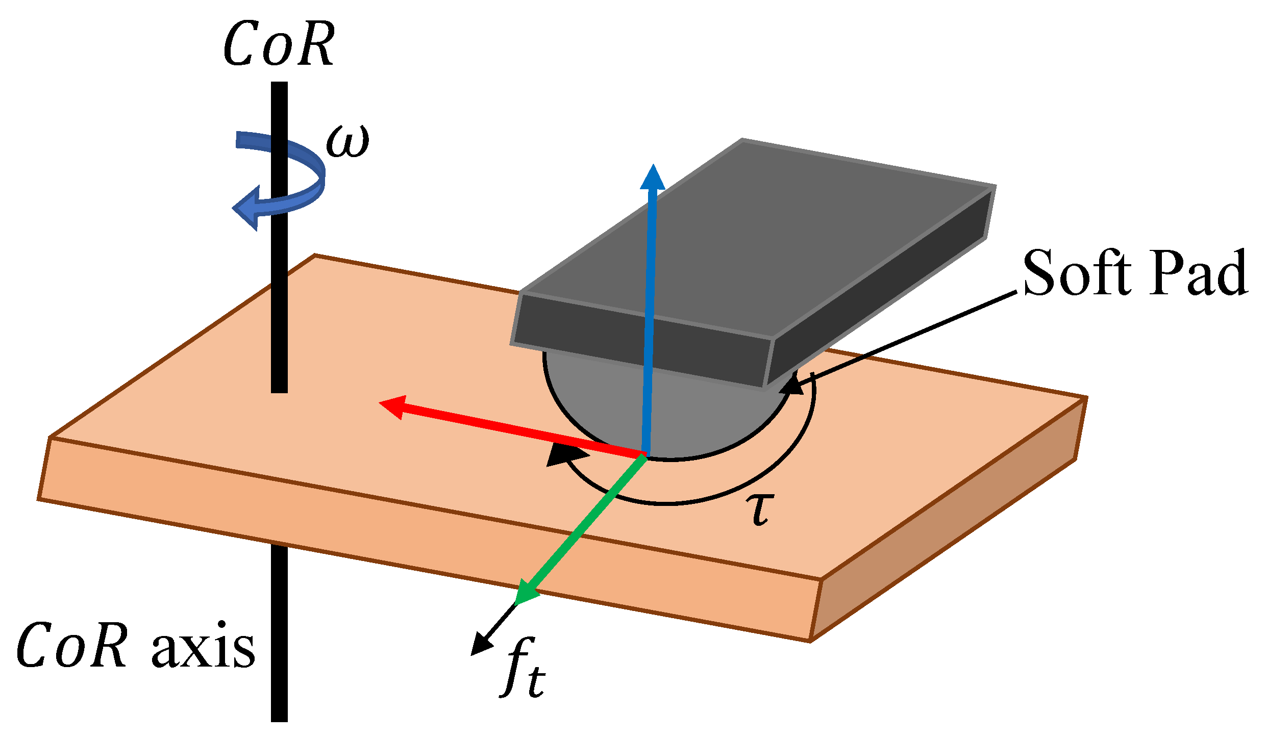
In this paper, the manipulated object is modeled as a planar slider. With reference to Figure 1, a planar slider is a rigid body that can rotate and translate in a 2-D space. The robotic finger is modeled as a hemispherical soft pad that makes contact with the slider with a non-zero contact area. This way, the fingertip exchanges both friction forces and torques with the slider. The friction can be indirectly controlled by acting on the normal force that the fingertip exerts on the body, which in turn changes the maximum friction force and torque that the contact can sustain.
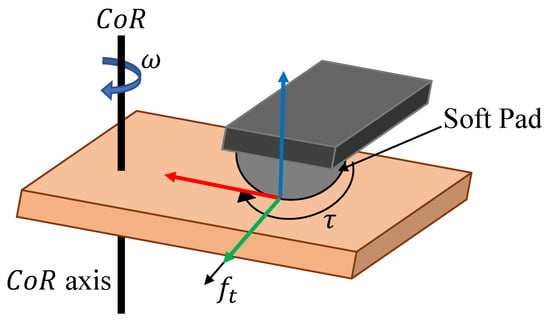
Figure 1.
Planar slider and the fingertip that exchanges force and torque with it. The CoR axis is highlighted.
Any 2-D roto-translational motion can be instantaneously described as a pure rotation about the CoR. Based on our previous friction modeling [19] and inspired by the revisited LuGre friction model [21], in this paper, we propose a novel planar slider dynamic model that considers the micro-damping between the micro-asperities in contact [21]. The slider motion about the CoR is modeled as
where is the external torque acting on the slider, is the slider’s rotational velocity about the CoR, z is the friction state variable, which represents the deflection of the micro asperities, and are the so-called stiffness and damping of the micro asperities, respectively, J is the inertia moment of the slider about the CoR; is the maximum rotational friction torque about the CoR depending on the normal force and the CoR position c, and finally, and are the dry and viscous friction torques, respectively. The relevant difference of the model in (1) and (2) with respect to the classical revisited LuGre friction model is the extension to the roto-translational case. This generalization is achieved by incorporating the LS method into the model and, specifically, in the computation of the maximum friction torque , which requires the estimation of the instantaneous CoR.
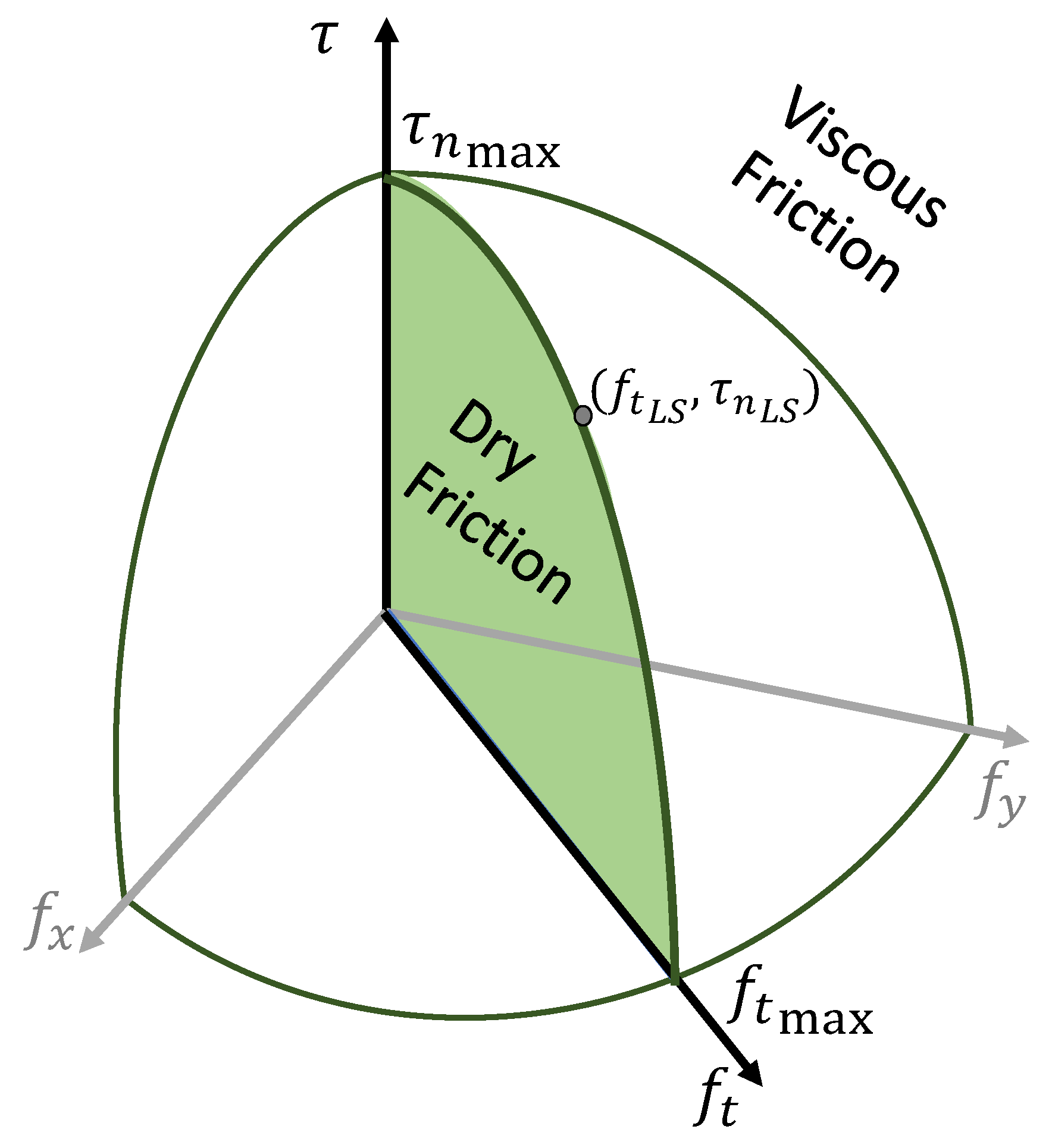
The only available control input is the normal force that is nonlinearly related to the maximum dry friction and the viscous one. The greater the value of , the greater the fingertip deformation (and the contact area), and the greater the available friction. This relationship can be found by resorting to the limit surface concept (LS) [18]. The LS is a closed surface defined in the space of the friction force and torque (Figure 2) and represents the maximum dry friction that a contact can sustain without sliding. With reference to Figure 1, we define a contact frame located in the center of pressure (CoP) of the contact area, with the y-axis along the direction of the tangential force and the z-axis normal to the contact surface and aligned to the normal force . It is well known that, assuming an axisymmetric pressure distribution [24], the limit surface is axisymmetric as well, and we can represent it using any radial cross-section. Moreover, the CoR position is always orthogonal to the tangential force, and, thus, it lies on the x-axis [18]. Consequently, it is possible to represent the CoR position with the scalar c. Finally, taking into account the load-motion inequality [12], the friction torque and c have opposite signs.
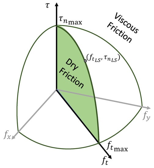
Figure 2.
Limit surface represented in the 3-D space.
Given one particular CoR position, it is possible to generate a point on the LS. Two values are of paramount importance: the point corresponding to a pure translation () and a pure rotation (), which represent the maximum possible values for the translational and torsional friction, respectively [24], i.e.,
where is the Coulomb friction coefficient, is a parameter that weakly depends on the particular pressure distribution and varies between (Hertzian) and (uniform) [18], and finally, and are additional parameters that relate the radius of the contact area to the normal force [24] according to the relationship .
The point on the LS (, ) can be computed as a function of the CoR position c [16]
where is the normalized CoR position, and and are known functions whose shape weakly depends on the parameter [16] and are shown in Figure 3. Given their very weak variation with respect to this parameter, in the following, we will consider the intermediate value already experimentally identified in [16].

Figure 3.
Graph of the functions and and their weak variation on the pressure distribution type.
The LS theory was originally conceived as an extension of the Coulomb dry friction for the rototranslational case. During the slippage, viscous friction should also be taken into account to describe the motion. Such a component is modeled by the term in (2). In our previous work [16], we extended the limit surface theory to also take into account the viscous friction, which corresponds to points in the force/torque space outside the LS (Figure 2). Thus, the viscous friction as a function of the CoR position can be expressed as
The dynamic model (1) and (2) describes the motion as a pure rotation about the CoR axis, and thus, it is important to estimate the CoR position. The LS theory is typically used to solve the forward problem given the CoR position (i.e., the instantaneous motion) by computing the friction force and torque. We are interested in the inverse problem, i.e., estimating the CoR position c given the measured friction force and torque. Moreover, when there is no motion (), the CoR is meaningless, but the dynamic model also needs the CoR to be defined in this case. To solve this issue, it is possible to define a virtual CoR [16], i.e., when the velocity is zero, the virtual CoR is the CoR that would result if we lowered the normal force down to the point that a sliding motion occurs. In the following, we will use the acronym CoR to refer to the CoR and the virtual CoR indistinctly.
To estimate the CoR from the measurements, it is useful to represent the LS in a space normalized with respect to the maximum friction force and torque (3) and (4). Applying such normalization, the complete expression of the normalized friction force and torque (i.e., the superposition of the dry (5) and (6) and viscous (7) and (8) components) can be written as
Such expressions relate the friction forces and torques with the CoR position c only outside and on the LS, but not inside it. To also define the CoR when the forces are inside the LS, we have to resort to the virtual CoR definition and consider what happens when the normal force varies. Inside the LS, there is no viscous friction; hence, the friction force and torque are simply given by the normalization formula
where the dependence on the normal force is in the definition of the maximum friction force and torque (3) and (4). The (virtual) CoR in such a case can be computed by considering that the sliding happens when is such that the point (, ) coincides with the normalized LS point (, ).
Finally, by combining (11) and (12) when the forces are inside the LS and (9) and (10) when they are outside it, the CoR position c can be estimated with the following algorithm:
where
and is the limit volume, i.e., the set of points inside the LS. The conditions in (13) can be easily checked by resorting to the convexity of the LS, i.e.,
Given the CoR position, it is possible to write the expression of the torques about the CoR axes needed by the dynamic system (1) and (2). The friction torque about the CoR axis can be obtained by transforming the wrench in the contact frame to a pure torque about the CoR axis as
By following the same arguments, the viscous friction torque in the dynamic equation can be computed with the same transformation, i.e.,
from which the expression of is straightforward. The maximum rotational friction can be computed in the same way. It is the LS point (, ) transformed as a pure torque about the CoR axis. It is important to underline that is always positive; it is the magnitude of the maximum friction, and and independently contribute to , i.e.,
where and are the same variables from (3) and (4) explicitly written as functions of the normal load .
3. Velocity Observer
The control law proposed in Section 5 needs the state of the system (1) and (2), which is not directly measurable. We need to estimate the state and, in particular, the sliding velocity of the planar slider by resorting to only force and torque measurement at the fingertips. To this aim, in addition to the state Equations (1) and (2), we also consider the following output equation:
which is the superposition of the dry and viscous friction torque about the CoR axis. The measurable output y can be obtained by the measured force and torque similarly to (16) as
where and are the components of the measured wrench at the fingertip.
It can be proved that the system (1), (2), and (19) is locally weakly observable [25], and, thus, it is possible to use the following nonlinear observer to estimate the velocity :
The observer structure is the same as the original dynamic system (1)–(2) with the measured friction y playing the same role of the external torque . The inertia moment is substituted by the observer gain l; the higher the gain, the faster the observer convergence. The local observability is proved by the following proposition.
Proposition 1
Proof.
The nonlinear system in (1), (2), and (19) can be written in the more compact form
where is the state vector, is a vector function whose components are the second members of the state-space Equations (1) and (2), and the output matrix is
According to [26], the local observability of the system (24) and (25) is ensured at any initial state if the following matrix has rank 2 :
where represents the Jacobian of the vector function , and represents the Lie derivative operator along of order 1.
For the system (24) and (25), can be written as
with being a version of the signum function regularized around zero, which means considering an absolute value function regularized around zero as well to make it differentiable. The rank of the matrix above would be lower than 2 if and only if
This equation has no solutions, nor does it in and in . In fact, for , it is equivalent to
which has no solutions because the LuGre friction model ensures that [21]. The same result holds for in the domain , yielding to the non-solvable equation
□
4. Data Collection and Parameter Estimation
The sliding velocity observer relies on the knowledge of the system physical parameters, which needs to be estimated. In particular, friction coefficients such as and are of paramount importance to detect the slip and estimate the slip velocity. For this reason, in this work, we conducted an extensive data collection campaign to validate the ability of the observer to estimate the sliding velocity.
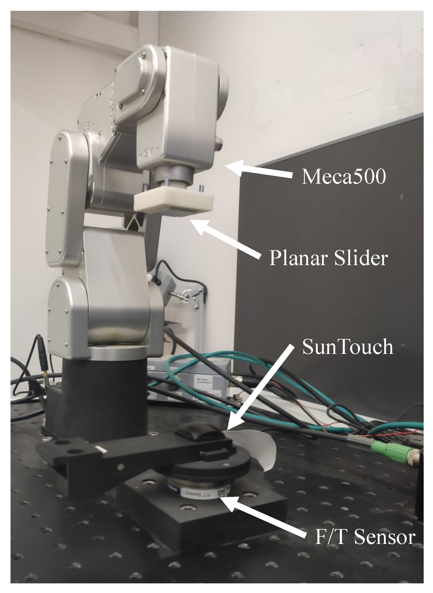
The experimental setup used to this aim is depicted in Figure 4. The SUNTouch finger was mounted on a reference 6-axis force/torque sensor, the ATI Nano43, by ATI Industrial Automation, USA, which was able to accurately measure the friction forces exchanged between the fingertip and the slider. The planar slider was a flat object rigidly mounted on a Meca500 robot by Mecademic Robotics, CA. The robot was commanded to push the slider against the fingertip and apply various combinations of forces and torques, resulting in sliding motions. The ground-truth velocity was measured as the robot end-effector velocity obtained via joint encoders and forward differential kinematics. The data were collected with a ROS network and MATLAB.
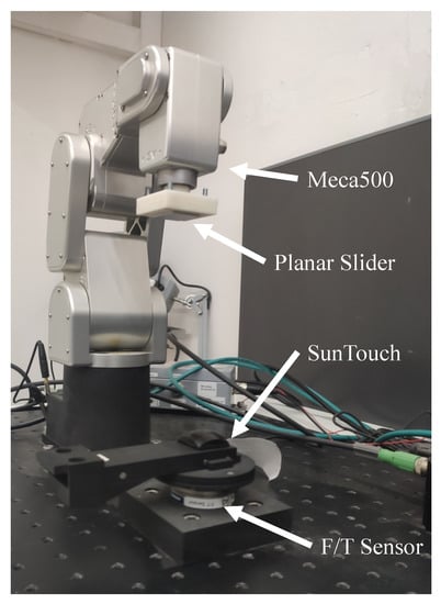
Figure 4.
Setup for data acquisition.
A cardboard layer was attached to the slider. If the slider was rigid, the deformation of the fingertip depended only on the soft fingertip material and not on the slider [24]; thus, the only parameters that depended on the slider were the friction parameters and . The remaining parameters can be estimated once and also used for other rigid planar sliders.
The parameter estimation problem can be formalized as the following optimization algorithm:
where is a discrete-time version of the observer (21) and (22), k is the sample-time instant, and N is the total number of samples. The vector contains the model parameters to be identified, i.e., , , , , , and . The time discretization of the observer equations is not trivial. The dynamics of the internal friction state variable z is very fast, yielding a very stiff equation. This means that simple numerical methods for solving the equation are numerically unstable unless the step size is extremely small. We found that, to discretize the observer, it was not possible to adopt the classical Euler discretization, thus, we adopted the fourth-order Runge–Kutta method (RK4).
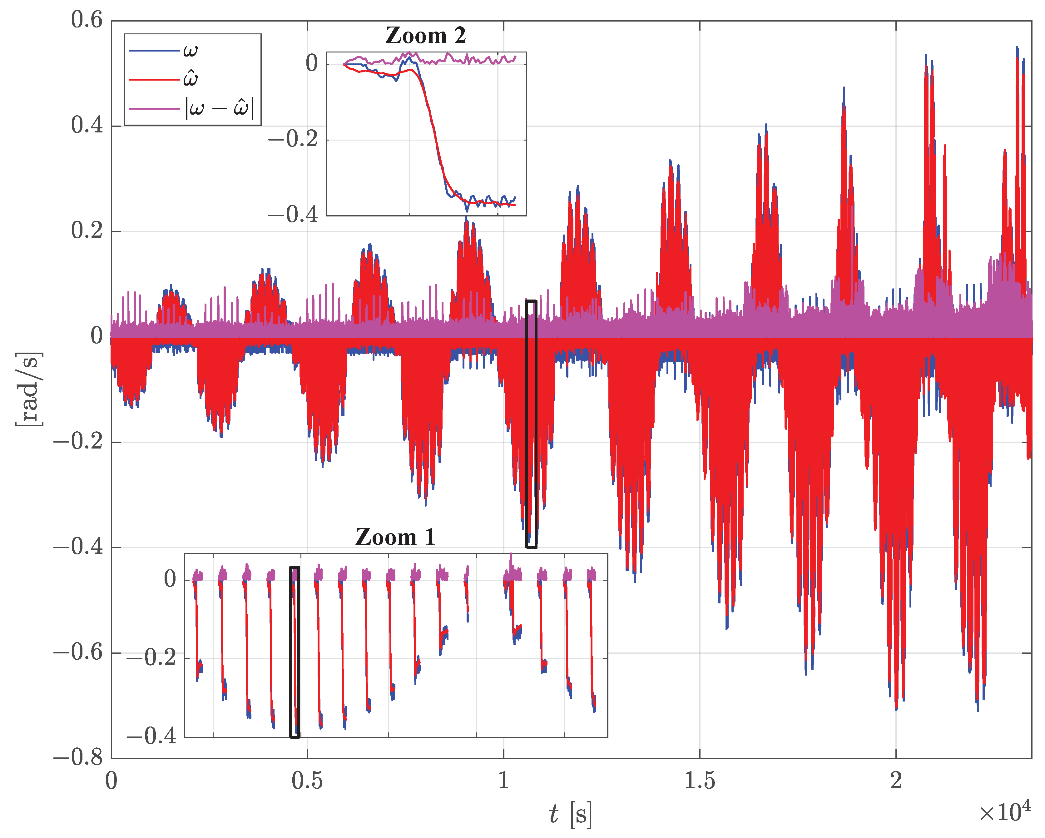
The results of the parameter estimation problem (32) are reported in Figure 5, and the corresponding parameters are in Table 1. The figure shows 1342 sliding maneuvers applied with the setup in Figure 4; the robot pushes the slider against the fingertip with increasing forces and torques, resulting in increasing sliding velocity. Finally, the ground-truth sliding velocity , together with the tangential force and torque measured by the F/T sensor, were used as input to the optimization problem (32) solved with the sequential quadratic programming (SQP) algorithm. To facilitate the convergence, it was useful to bound the parameter space. Some parameters could be theoretically bounded (e.g., [24]), and others could be roughly estimated with a single sliding maneuver. Thus, it was also possible to provide a reasonable initial guess for the optimization algorithm. The resulting parameters (Table 1) yielded the estimated velocity in Figure 5 (red line). The results clearly show that the velocity observer is able to correctly estimate the ground-truth sliding velocity and catches all the sliding events with a root-mean-square error (RMSE) of rad/s.
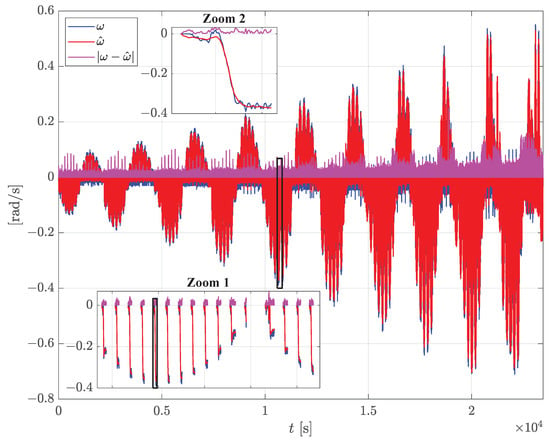
Figure 5.
Results of the estimation of the slippage velocity after the estimation of parameters with a cardboard slider. Ground-truth robot velocity (blu), estimated velocity (red), estimation error (magenta). The inner plots are zooms that show details of the single repetitions; the zoomed areas are highlighted in the black boxes.

Table 1.
Model parameters estimated on a rigid cardboard slider.
5. Sliding Controller
This section presents a novel slipping control strategy based on the observer presented in the previous section. The basic idea is similar to the one presented in our previous work [16], but with a substantial difference: the control law involves the full state feedback estimated by the observer.
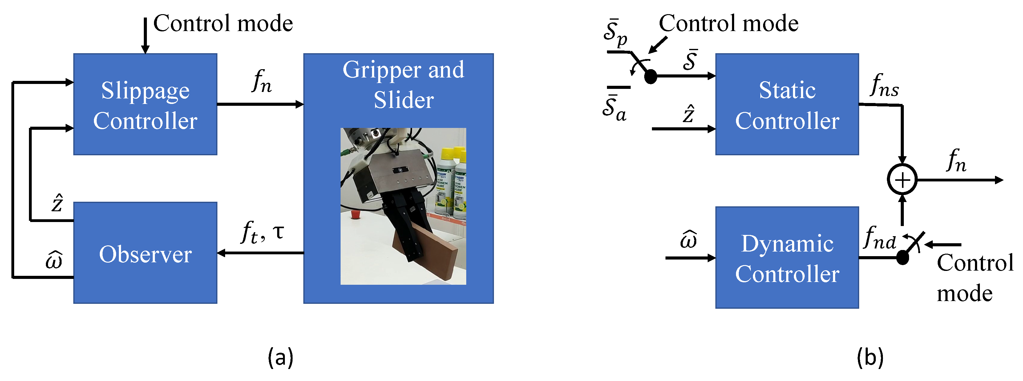
The control scheme works in two possible control modes, “slipping avoidance” and “pivoting”. With reference to Figure 6a, in slipping avoidance mode, the objective of the sliding controller is to regulate the estimated slipping velocity to zero by modulating the grasping force . The pivoting mode allows an in-hand manipulation; it consists of letting a manipulated object rotate in hand subject to the gravity so as to change the relative orientation between the gripper and the object. In this modality, the controller allows rotational sliding between the fingertip and the slider. The control strategies for the two control modalities are very similar. We will describe the slipping avoidance mode first, in which all the control components are active.
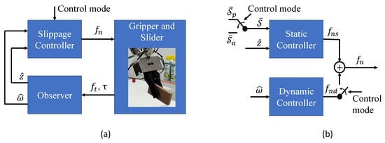
Figure 6.
Control scheme: (a) closed loop system with the interconnections; (b) details of the slippage controller. The control mode can be either slipping avoidance or pivoting.
The control law is composed of two components (Figure 6b):
where is the static contribution and represents the normal force that is able to avoid the slippage by bringing the maximum torsional friction around the CoR above the actual dry friction in (1) and (2). It is computed by exclusively using the estimated dry friction and not the viscous friction, yielding lower grasping forces with respect to the strategy in [16]. The static contribution is able to avoid slippage only in static or quasi-static conditions. In fact, it is well-known that when the load is time-varying, the maximum friction that the contact between the slider and the fingertip can sustain decreases as the rate of variation of the load increases [27]. Thus, the dynamic contribution is introduced, and it is synthesized by means of the estimated velocity as
where is a suitable linear differential operator, and the absolute value operator ensures that both for positive and negative slipping velocities. can be represented with a transfer function
where the real zero and pole ( and , respectively) were selected to reduce the high-frequency gain () so as to reduce the control sensitivity to the high-frequency noise. The gain was selected to obtain a quick reaction to any relative velocity . The parameters of the controller were tuned to the values , , .
The static contribution was designed by resorting to the feedback of the estimated friction state variable . The main idea was the definition of the following slippage indicator
It is well-known that the LuGre state z is bounded by the maximum friction [21], and it always holds that . In particular, when , the dry friction has reached its maximum, and slippage can take place. This implies that the slippage indicator , and, when , the slider can slip with respect to the finger. Moreover, note that the greater the grasp force , the greater the maximum friction ; thus, decreases as increases. Given these considerations, the objective of the static contribution is to regulate the slippage indicator to the value designed, taking into account the desired degree of slipping avoidance robustness. The lower the value of , the greater the resulting grasp force. In the experiment section, we will select . The regulation of is carried out by a classical PI controller with the proportional gain and the integral gain tuned so as to obtain the fastest possible response time with the hardware used in the experiments (Section 6).
In pivoting mode, which is the controlled sliding maneuver considered here, the control scheme is almost the same as the slipping avoidance mode, as depicted in Figure 6b. This time, the objective is to allow slippage; has to be regulated to 1, and the grasping force has to be continuously decreased as long as the sliding motion is complete. To this aim, it is sufficient to activate the switches in Figure 6b. The dynamic contribution is deactivated () because the sliding velocity does not have to be controlled to zero, and the reference slippage indicator is set to the value . Additionally, the static control law is switched to a first-order filter with a time constant . This way, the grasp force will decrease down to the point for which reaches its maximum; then, the constant error will cause an exponential decrease in the static contribution governed by the time constant . As soon as the pivoting motion has been completed, the slipping avoidance mode is reactivated.
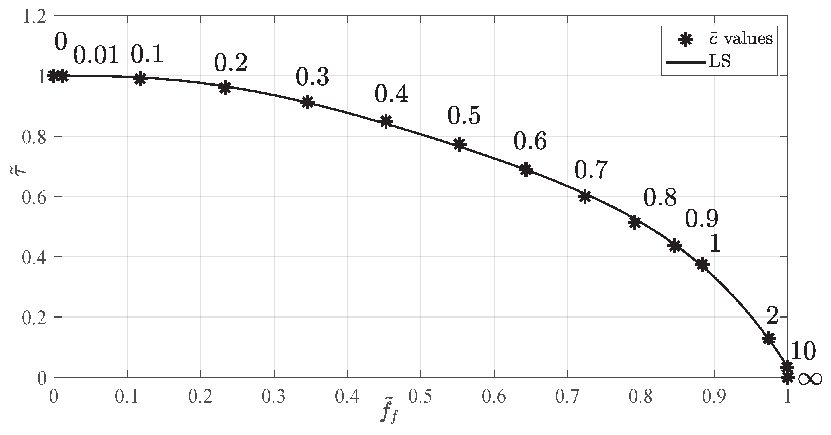
At the beginning of the pivoting, the object is grasped far from its center of gravity (CoG), and the friction sustains the gravitational torque. Decreasing the grasp force would cause the object to rotate about the grasp axis in a pendulum-like motion until its equilibrium point, where the gravitational torque is zero and the object is in a “vertical” configuration (with the CoG just below the grasp axis). In the beginning, the object is more prone to rotationally slide subject to the torque; at the end, the object is more prone to translate. These two phases can be discriminated by the estimated CoR position (13); low values of mean that the object will rotate, and high values mean that the object will translate. This can be graphically visualized in Figure 7. The figure shows the normalized LS parametrized with respect to . Low values of correspond to high-friction torque values and vice versa. Thus, can be used in the pivoting mode to detect the end of the pivoting maneuver and stop the decreasing of the grasping force. In the experiments, as soon as the normalized CoR position is such that , the pivoting maneuver is considered completed.
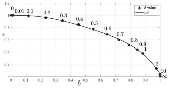
Figure 7.
Normalized LS with the corresponding values of .
6. Experiments
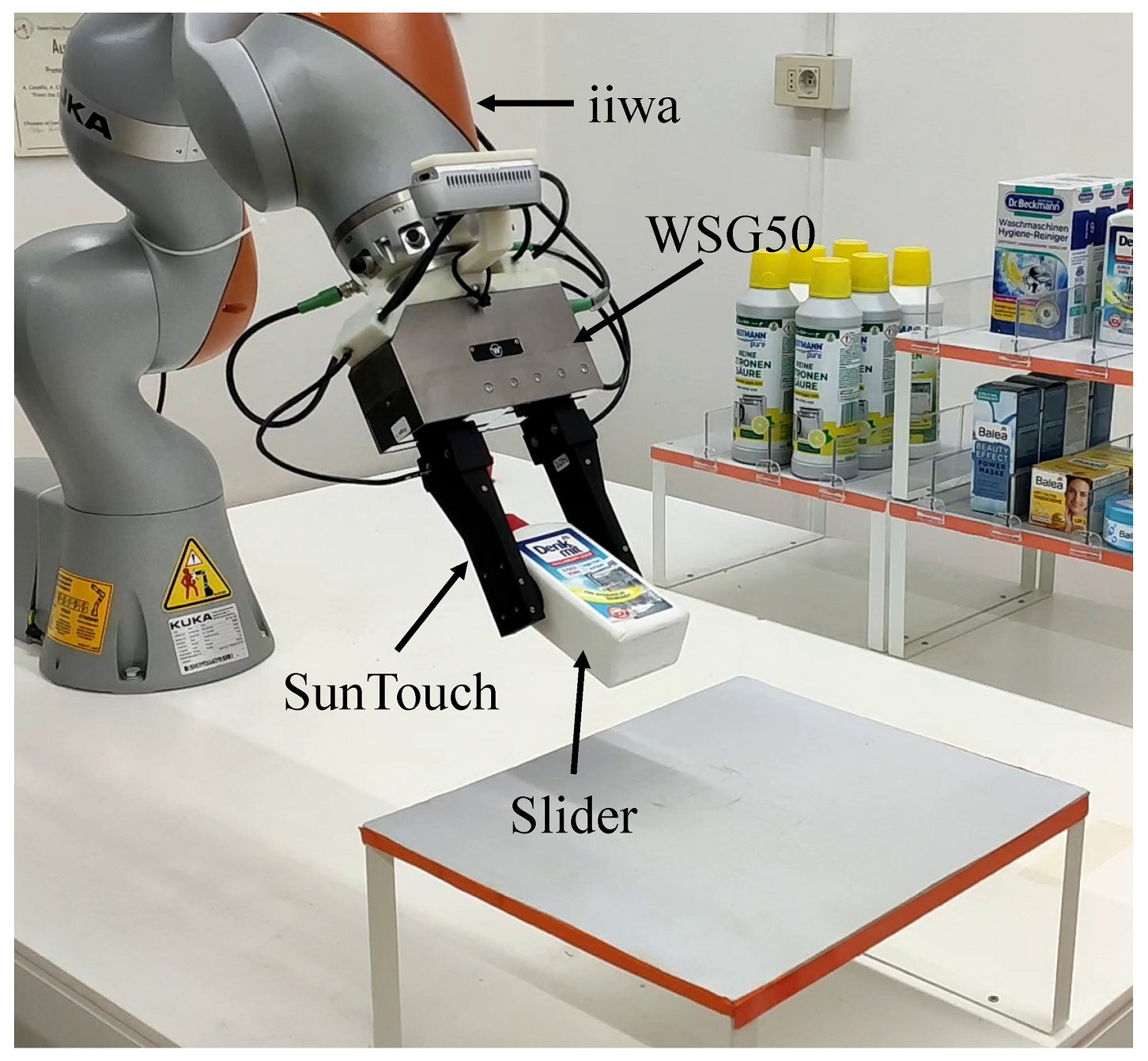
This section presents a series of experiments performed on a real system to evaluate the control strategy presented in Section 5. The experiments were carried out in a lab-scale in-store logistic scenario [28,29]. The experimental setup for the manipulation experiments is depicted in Figure 8.
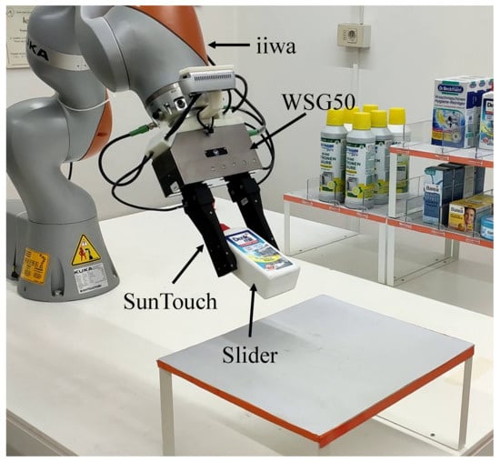
Figure 8.
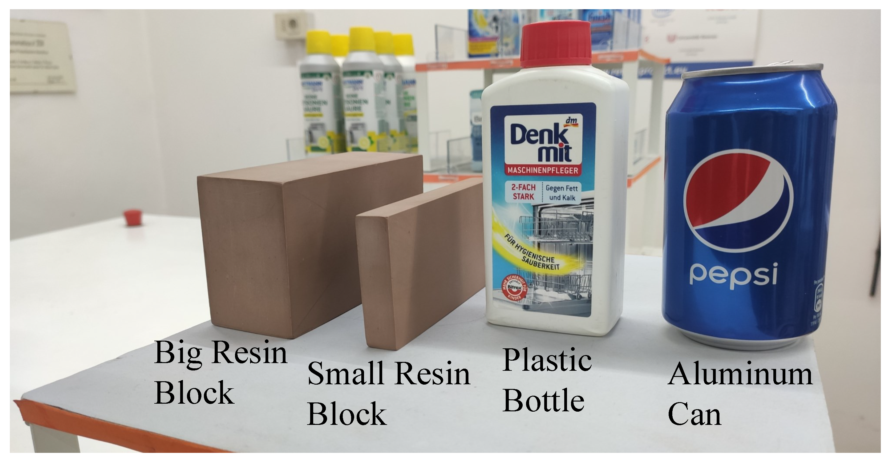
Manipulated objects. From left to right: big resin block, small resin block, plastic bottle, aluminum can.
The grasping device was a commercial 1DOF WSG50 parallel gripper by Weiss Robotics, DE, equipped with the SUNTouch force/tactile sensor [8] designed and produced in our laboratory. The sensor has an accuracy of N and Nm in the measurement of forces and torsional moments, respectively. This end effector was mounted on a LBR iiwa robot by Kuka, DE, and the whole system was controlled via a ROS network. The gripper was commanded at 50 Hz, the fingertips provided the tactile data at 500 Hz, and the iiwa robot was controlled via the FRI interface at 1 kHz.
Four objects were selected (Figure 9): two resin blocks (a big and a small one), a plastic bottle, and an aluminum can. We considered the objects rigid so that all the parameters, except and , estimated in Section 4 could also be used with these objects. Obviously, not all the objects in Figure 9 were perfectly rigid, but we could approximate them as rigid compared to the sensor soft pad. The two remaining friction coefficients and could be roughly estimated online by rubbing the fingertips on the object and comparing the measured force with the robot velocity with a procedure similar to the one described in [30]. The object-dependent parameters are reported in Table 2.
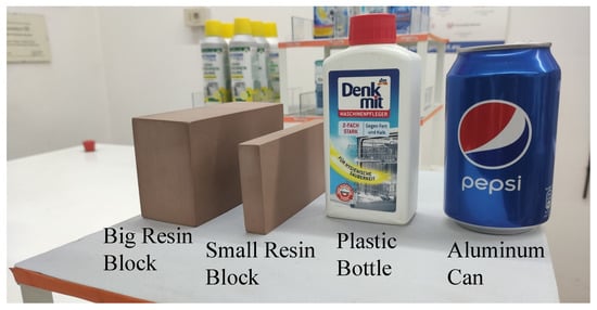
Figure 9.
Experimental setup.

Table 2.
Friction parameters estimated for the manipulated objects.
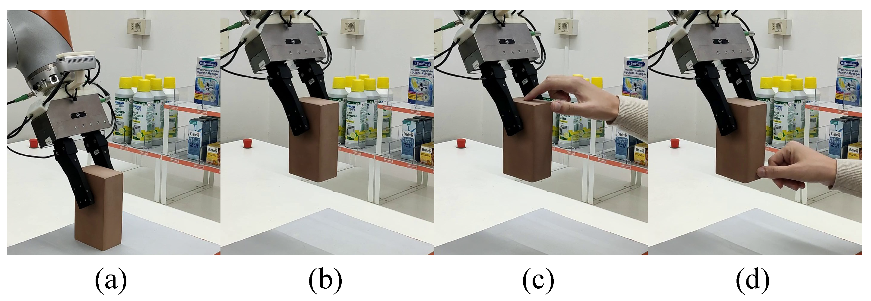
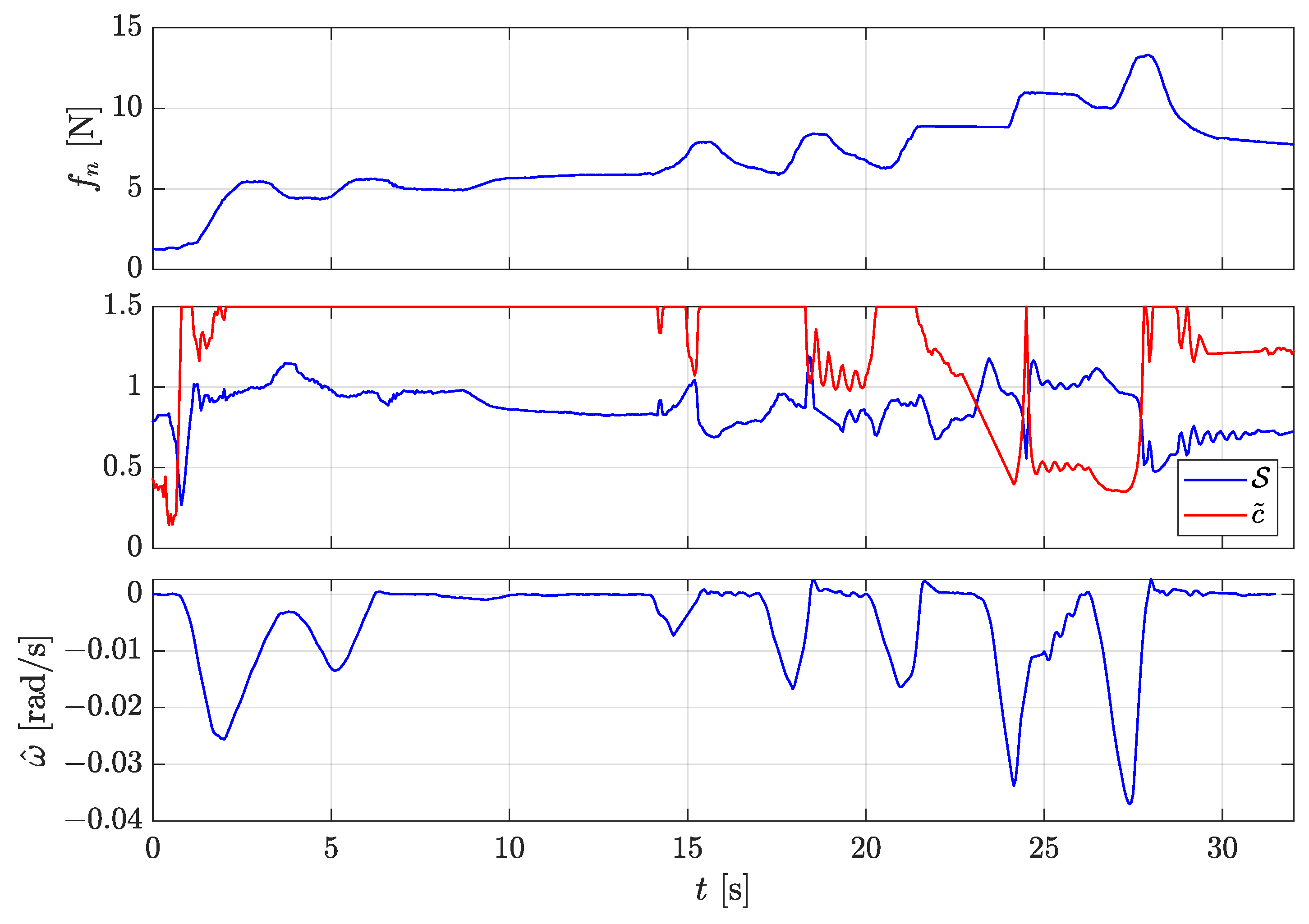
The first experiment involved the big resin block. At the beginning, the block rested vertically on the picking desk, and the robot was commanded to grasp it above its CoG (Figure 10a) and lift it. As soon as the gripper grasped the object, the slipping avoidance algorithm was activated. The results are shown in Figure 11. At s, the lift began, the sudden increment of the external load due to the object weight caused the velocity observer to detect a sliding velocity. Thanks to the dynamic contribution, the controller responded by increasing the grasp force up to 5 N. Since the object was grasped above the CoG and almost no gravitational torque was applied to the fingertip, after the lift (Figure 10b), the estimated normalized CoR position was high (middle plot red line). The CoR should be theoretically infinity in this condition; however, to avoid numerical issues, we saturated the normalized CoR to an upper limit of . When the lift was completed and all the dynamic effects vanished, the static contribution stabilizes our slippage indicator (middle plot, blue line) to the reference value . To test and stress our algorithm, at s, a human operator applied various disturbance forces by hands on the resin block (Figure 10c,d). The observer detected such events as slippage velocity peaks that were counteracted by the dynamic contribution. At the same time, as soon as the disturbances were applied, the slippage indicator increased, and the static controller also helped to regulate the force to higher values.
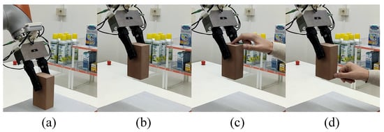
Figure 10.
Snapshots of the first experiment: (a) grasp configuration; (b) after lifting; (c,d) disturbance applied by a human operator.
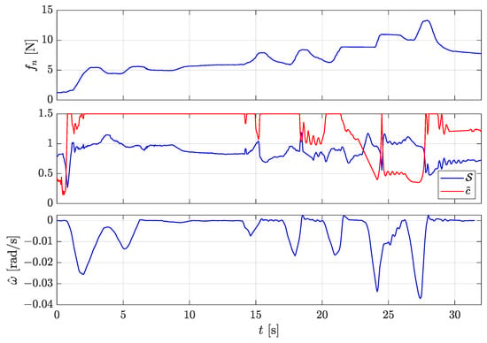
Figure 11.
First experiment: lifting the big resin block. Top plot: grasping force. Middle plot: slippage indicator (blue) and estimated (red). Bottom plot: estimated slippage velocity around the CoR .
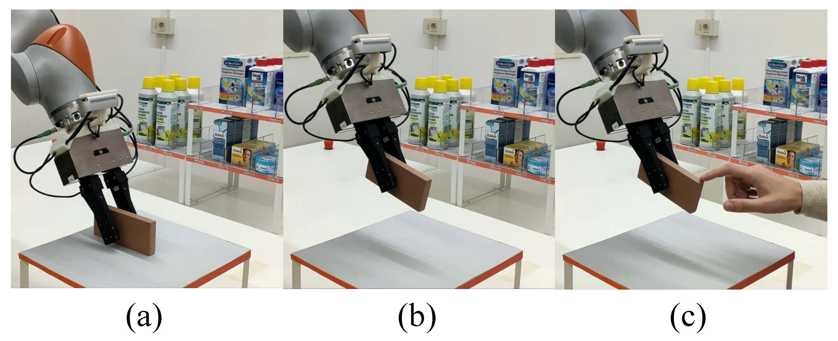
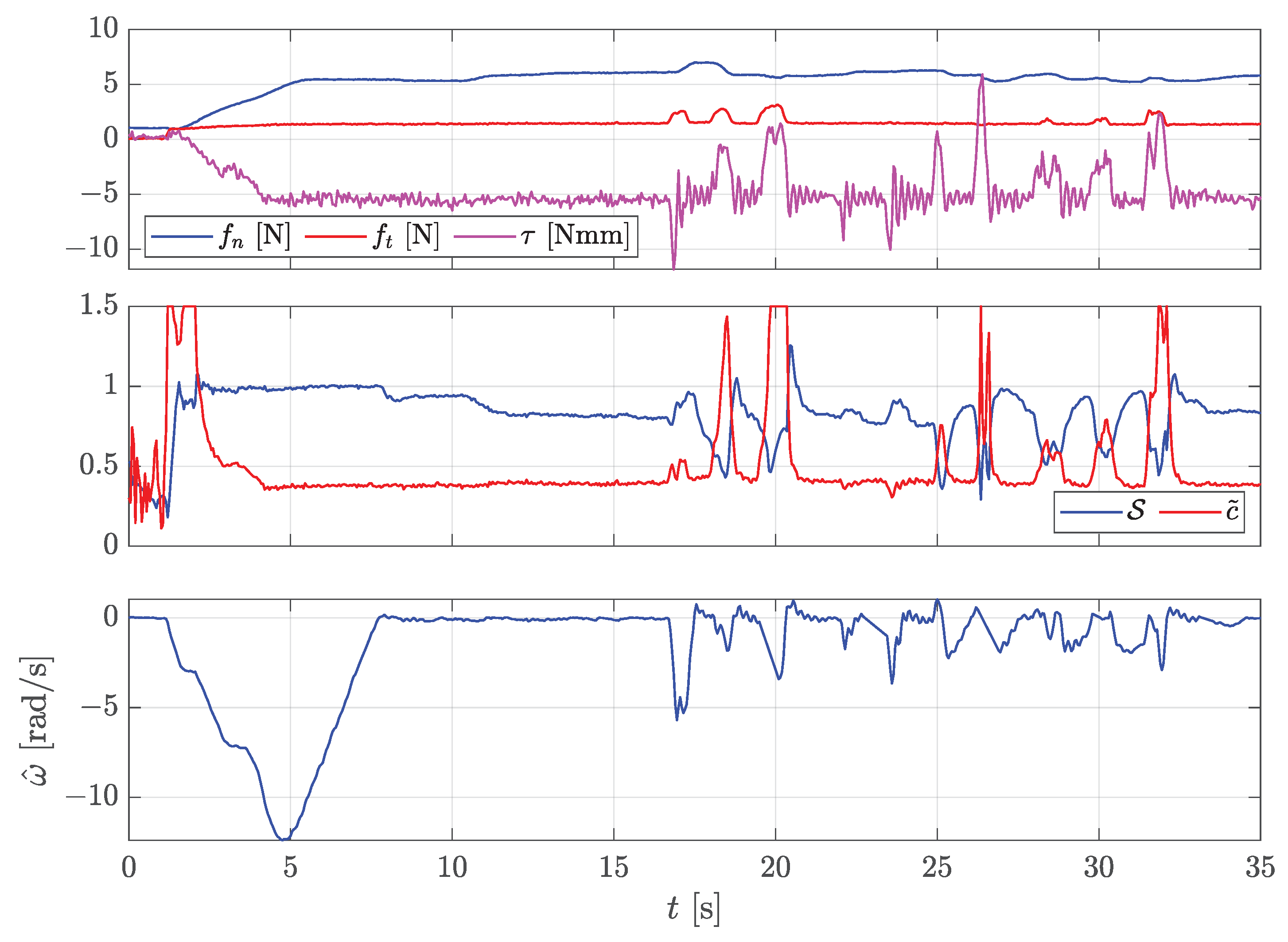
The second experiment was carried out with the lighter small resin block. This time, the block rested horizontally on the picking desk (Figure 12a), and the robot did not grasp it in its CoG so that a gravitational torque was applied on the fingertips. The results are shown in Figure 13. Once again, as soon as the lift began, the observer estimated a slippage velocity (bottom plot), and the controller responded by increasing the grasping force (top plot, blue line). Even if the small black was lighter than the big one, after the lift (Figure 12b), the grasping force reached similar values (5 N). This was because this time, the torsional moment (top plot, magenta line) also had to be sustained. The effects of the torsional load were also evident in the estimated CoR position . In the previous experiment, it was saturated to , but now, the CoR estimation algorithm computed a much lower value, i.e., . This means that, if the grasping force decreased, the slider would be more prone to a rotation than a translation. Additionally, in this experiment, the control algorithm was stressed at s by applying disturbances (Figure 12b). Even in this different configuration, the results were analogous to the previous experiment. As soon as the disturbances were applied, the observer detected slippage velocity peaks, and the controller responded by increasing the grasping force to avoid the slippage.
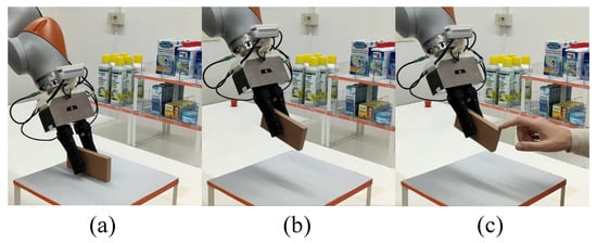
Figure 12.
Snapshots of the second experiment: (a) grasp configuration; (b) after lifting; (c) disturbance applied by a human operator.
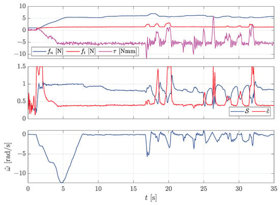
Figure 13.
Second experiment: lifting the small resin block far from the CoG. Top plot: grasping force (blue), tangential load (red), torsional torque (magenta). Middle plot: slippage indicator (blue) and estimated (red). Bottom plot: estimated slippage velocity around the CoR .
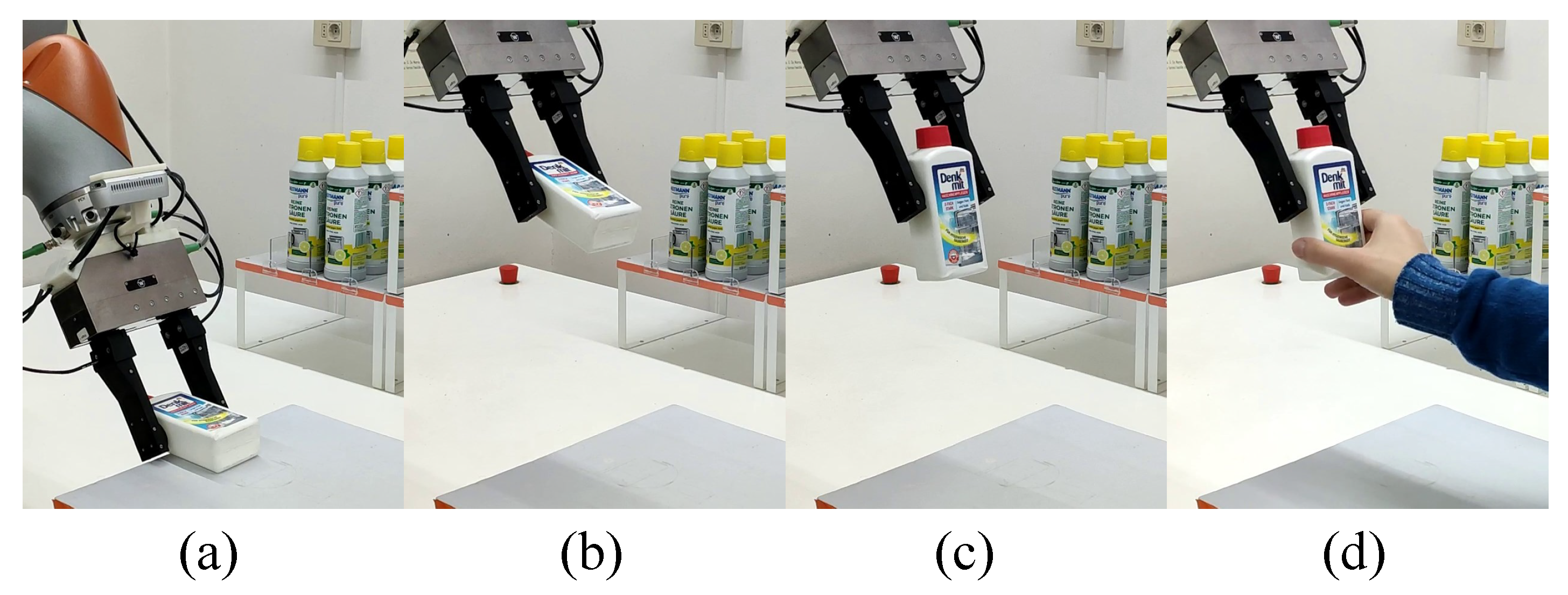
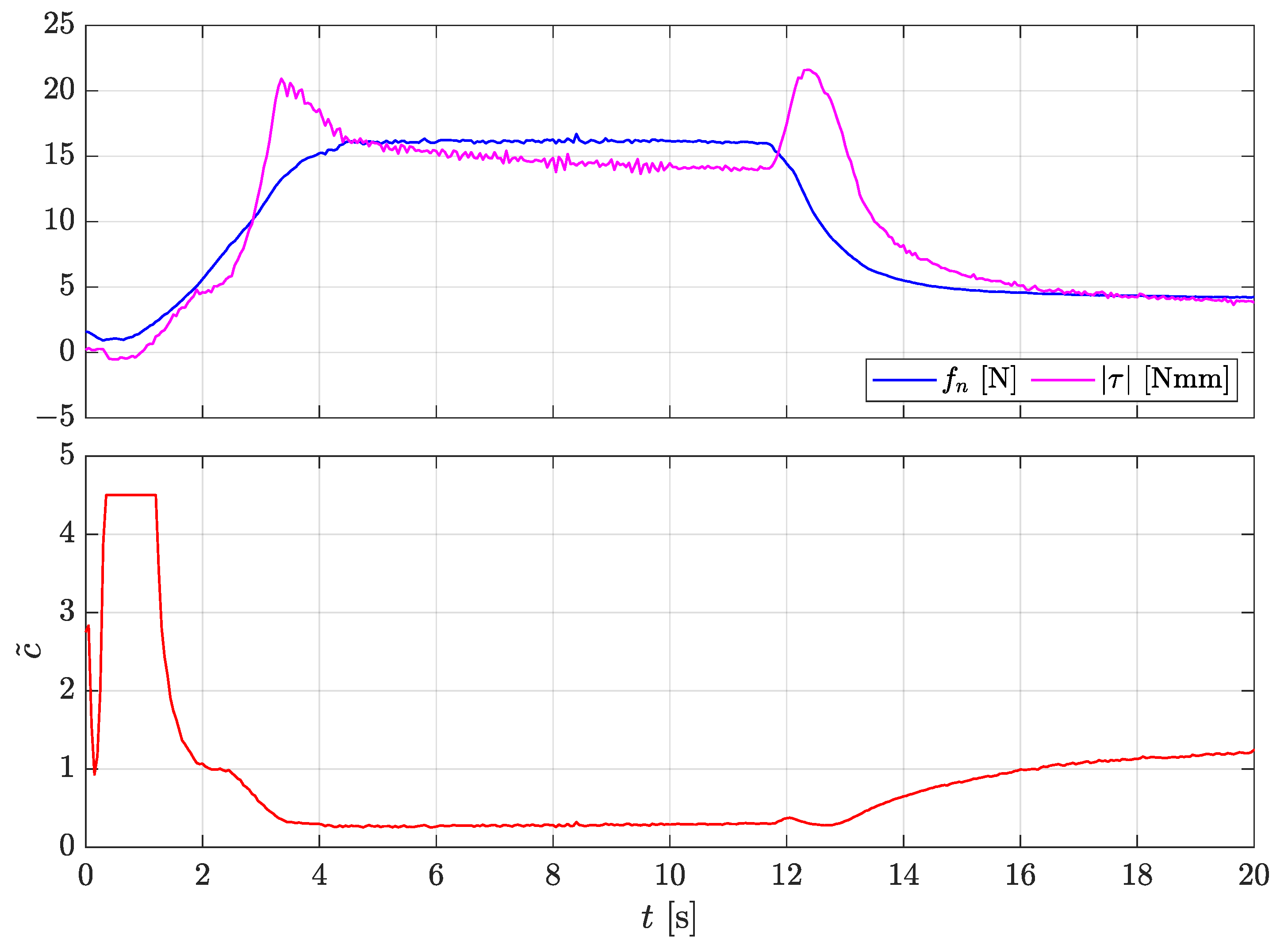
The third experiment shows how the manipulation ability developed in this work can be used in a collaborative scenario. The robot had to grasp a plastic bottle that was knocked over the picking desk (Figure 14a) and had to hand it over to a human partner in a vertical orientation. The results are shown in Figure 15. The first phase was similar to the previous experiment. The robot grasped the bottle far from its CoG so that the slippage controller had to also counteract the gravitational torque. This time, after the lift ( s, Figure 14b), the measured torque (top plot, magenta line) increased up to 15 Nmm, and the slippage controller automatically modulated the grasping force to 16 N (top plot, blue line). In this configuration, the estimated CoR position was very low (, bottom plot). Thanks to this information, we can tell in advance that, if the grasping force is decreased, the manipulated object would start to rotationally slip about the grasp axis, and the translational slippage would be negligible. This means that it is possible to activate the pivoting control modality to reorient the object in hand to the vertical configuration depicted in Figure 14c. At s the pivoting began, the grasp force exponentially decreased, and the bottle started to rotate. Since the object was moving, the viscous friction caused an initial increment of the torsional torque, but, as the object rotated toward the vertical configuration, the gravitational torque decreased. While the bottle rotated, the CoR increased, and as soon as (at s), the pivoting maneuver was considered completed and the grasp force stopped its descent since the object had reached the configuration in Figure 14c and can be handed over to the human partner. The final handover phase (Figure 14d) and the control of the forces exchanged between the robot and the human was carried out with the algorithm in [31].
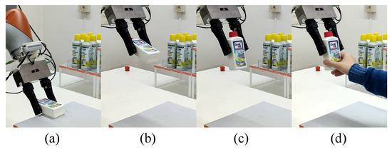
Figure 14.
Snapshots of the third experiment: (a) grasp configuration; (b) after lifting; (c) after pivoting; (d) handover.
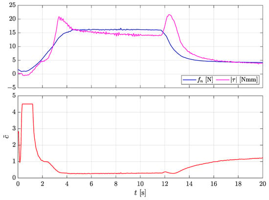
Figure 15.
Third experiment: lifting the plastic bottle far from the CoG. Top plot: grasping force (blue), torsional torque (magenta). Bottom plot: estimated .
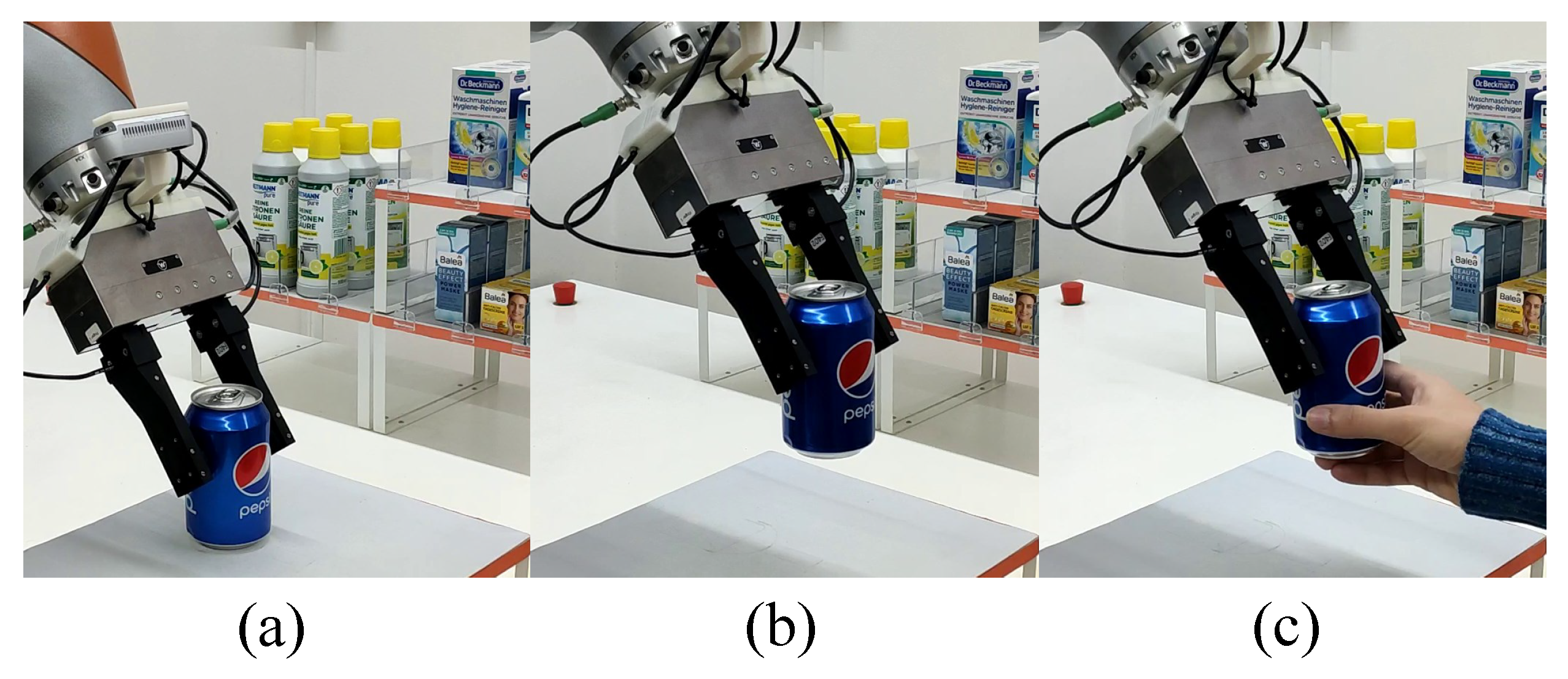
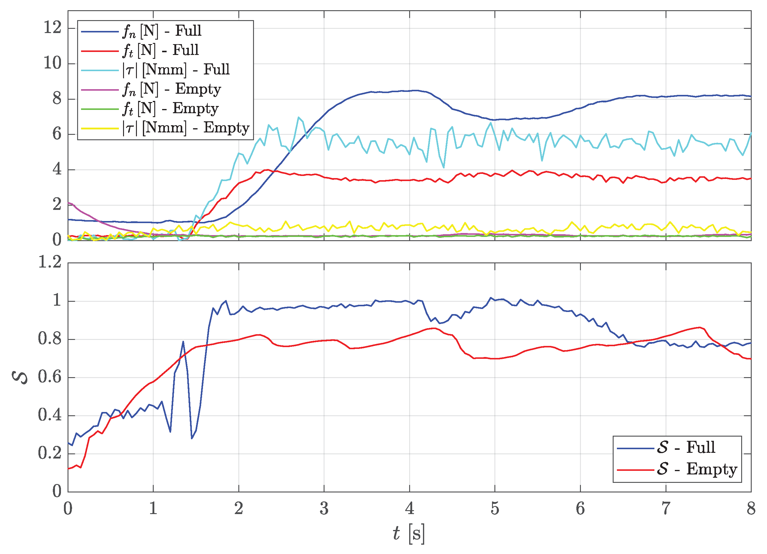
The fourth experiment demonstrates the slipping avoidance algorithm’s ability to automatically choose the grasp force when handling objects of very different weights. The objective of this experiment was to hand the aluminum can over to a human partner. The task was repeated two times with a full and an empty can, respectively. The can was grasped above its CoG, as shown in Figure 16a. The results are shown in Figure 17. The top plot shows the grasp force synthesized by the slipping controller as well as the measured tangential and torsional loads. After the lift ( s, Figure 16a), the forces reached very different values in the two task repetitions. When the can was full, the tangential load was 4 N, while the torsional load was 6 Nmm; thus, the controller applied a grasping force of 8 N to avoid slippage. When the can was empty, it was much lighter: the tangential force was N, and the torsional moment was almost zero. Thus, the controller needed a very low grasp force of N to safely hold the aluminum can without damaging it.
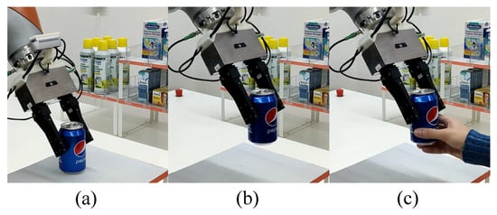
Figure 16.
Snapshots of the fourth experiment: (a) grasp configuration; (b) after lifting; (c) handover.
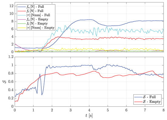
Figure 17.
Fourth experiment: lifting the aluminum can. Top plot: grasp force, tangential force, and torsional moment for the full can (blue, red, and cyan respectively), grasp force, tangential force, and torsional moment for the empty can (magenta, green, and yellow respectively). Bottom plot: slippage indicator for the full and empty cans (blue and red, respectively).
A video of all the experiments is available as Supplementary Material (Video S1).
7. Discussion
The experimental results presented so far give evidence of the ability of the robot to handle different types of objects made of different materials (resin, plastic, and metal) and with large differences in their weight and friction properties. The robot is able to grasp and lift the objects without any knowledge of their weight by applying the minimum grasping force to hold them without any translational or rotational slippage. This is shown especially in the lifting of the empty aluminium can, which requires a grasping force as low as N, while lifting the full can requires a 40 times larger force. The manipulation ability of the robot is not limited to safely grasping any object with no slipping; the grasp force can be suitably controlled to allow an intentional slip, which might be useful to change object orientation in hand even with a simple parallel gripper. The selection of a model-based manipulation method is motivated by the objective of allowing the robot to manipulate different types of objects without requiring an excessive learning and training burden. Indeed, the off-line learning phase is limited to the experimental identification of a few parameters of a friction dynamic model that is the basis of the manipulation control strategy. The few remaining parameters that depend on the specific object to be handled are estimated at run time by a simple and quick exploration phase (see the accompanying video). The main limitations of the method, at the present development stage, are related to the limited accuracy of the force/tactile sensor when it interacts with largely deformable objects and with rigid objects characterized by a curvature radius smaller than the one of the soft pad. Moreover, the model learning phase, even though robotized, is still quite lengthy.
8. Conclusions
This paper presented a model-based control strategy for slipping avoidance and pivoting using a simple parallel gripper. The control system is able to automatically regulate the grasping force without knowing the object’s weight, instead using the measurement of the friction force and torque between the fingertip and the manipulated object. The revisited model presented in this paper is used to build a slippage observer that has been validated with more than a thousand sliding manoeuvres at different velocities and forces. By using the full-state feedback of the observer, we proposed a novel sliding control scheme that considers the internal friction state by defining a novel slippage indicator to be suitably controlled to the desired value. The experimental tests evaluated the proposed control scheme in a lab-scale real-world environment in which the robot manipulated everyday objects that differed in weight, material, and grasp configuration. Future research efforts will be devoted to exploring sensor calibration methods more suitable for deformable objects and to generalize the manipulation control to multi-fingered hands, where not only the magnitude but also the direction of the grasping forces can be exploited to control the object grasp and its in-hand manipulation.
Supplementary Materials
The following supporting information can be downloaded at: https://www.mdpi.com/article/10.3390/app13020921/s1, Video S1: Video of the Experiments.
Author Contributions
Conceptualization, M.C. and G.D.M.; Methodology, M.C. and G.D.M.; Software, M.C.; Writing—original draft, M.C., G.D.M. and C.N.; Writing—review and editing, C.N. All authors have read and agreed to the published version of the manuscript.
Funding
This research received no external funding.
Institutional Review Board Statement
Not applicable.
Data Availability Statement
Not applicable.
Conflicts of Interest
The authors declare no conflict of interest.
Abbreviations
The following abbreviations are used in this manuscript:
| CoG | Center of Gravity |
| CoR | Center of Rotation |
| CoP | Center of Pressure |
| LS | Limit Surface |
| SQP | Sequential Quadratic Programming |
References
- Johansson, R.S.; Flanagan, J.R. Coding and use of tactile signals from the fingertips in object manipulation tasks. Nat. Rev. Neurosci. 2009, 10, 345–359. [Google Scholar] [CrossRef] [PubMed]
- Dahiya, R.S.; Mittendorfer, P.; Valle, M.; Cheng, G.; Lumelsky, V.J. Directions Toward Effective Utilization of Tactile Skin: A Review. IEEE Sens. J. 2013, 13, 4121–4138. [Google Scholar] [CrossRef]
- Kappassov, Z.; Corrales, J.A.; Perdereau, V. Tactile sensing in dexterous robot hands—Review. Robot. Auton. Syst. 2015, 74, 195–220. [Google Scholar] [CrossRef]
- Yuan, W.; Li, R.; Srinivasan, M.A.; Adelson, E.H. Measurement of shear and slip with a GelSight tactile sensor. In Proceedings of the 2015 IEEE International Conference on Robotics and Automation (ICRA), Seattle, DC, USA, 26–30 May 2015; pp. 304–311. [Google Scholar]
- Yuan, W.; Dong, S.; Adelson, E.H. GelSight: High-Resolution Robot Tactile Sensors for Estimating Geometry and Force. Sensors 2017, 17, 2762. [Google Scholar] [CrossRef] [PubMed]
- Abad, A.C.; Ranasinghe, A. Visuotactile Sensors with Emphasis on GelSight Sensor: A Review. IEEE Sens. J. 2020, 20, 7628–7638. [Google Scholar] [CrossRef]
- De Maria, G.; Natale, C.; Pirozzi, S. Force/tactile sensor for robotic applications. Sens. Actuators A Phys. 2012, 175, 60–72. [Google Scholar] [CrossRef]
- Costanzo, M.; De Maria, G.; Natale, C.; Pirozzi, S. Design and Calibration of a Force/Tactile Sensor for Dexterous Manipulation. Sensors 2019, 19, 966. [Google Scholar] [CrossRef]
- Costanzo, M.; De Maria, G.; Natale, C. Two-Fingered In-Hand Object Handling Based on Force/Tactile Feedback. IEEE Trans. Robot. 2020, 36, 157–173. [Google Scholar] [CrossRef]
- Chen, W.; Khamis, H.; Birznieks, I.; Lepora, N.F.; Redmond, S.J. Tactile Sensors for Friction Estimation and Incipient Slip Detection—Toward Dexterous Robotic Manipulation: A Review. IEEE Sens. J. 2018, 18, 9049–9064. [Google Scholar] [CrossRef]
- Reinecke, J.; Dietrich, A.; Schmidt, F.; Chalon, M. Experimental comparison of slip detection strategies by tactile sensing with the BioTac® on the DLR hand arm system. In Proceedings of the 2014 IEEE International Conference on Robotics and Automation (ICRA), Hong Kong, China, 31 May–7 June 2014; pp. 2742–2748. [Google Scholar]
- Goyal, S.; Ruina, A.; Papadopulous, J. Planar sliding with dry friction, part I. Limit surface and moment function. Wear 1991, 143, 307–330. [Google Scholar] [CrossRef]
- Li, J.; Dong, S.; Adelson, E. Slip Detection with Combined Tactile and Visual Information. In Proceedings of the 2018 IEEE International Conference on Robotics and Automation (ICRA), Brisbane, QLD, Australia, 21–25 May 2018; pp. 7772–7777. [Google Scholar]
- Zapata-Impata, B.S.; Gil, P.; Torres, F. Learning Spatio Temporal Tactile Features with a ConvLSTM for the Direction of Slip Detection. Sensors 2019, 19, 523. [Google Scholar] [CrossRef]
- James, J.W.; Lepora, N.F. Slip Detection for Grasp Stabilization With a Multifingered Tactile Robot Hand. IEEE Trans. Robot. 2021, 37, 506–519. [Google Scholar] [CrossRef]
- Costanzo, M. Control of robotic object pivoting based on tactile sensing. Mechatronics 2021, 76, 102545. [Google Scholar] [CrossRef]
- Veiga, F.; Edin, B.; Peters, J. Grip Stabilization through Independent Finger Tactile Feedback Control. Sensors 2020, 20, 1748. [Google Scholar] [CrossRef]
- Howe, R.; Cutkosky, M. Practical Force-Motion Models for Sliding Manipulation. Int. J. Robot. Res. 1996, 15, 557–572. [Google Scholar] [CrossRef]
- Cavallo, A.; Costanzo, M.; De Maria, G.; Natale, C. Modeling and slipping control of a planar slider. Automatica 2020, 115, 108875. [Google Scholar] [CrossRef]
- Canudas de Wit, C.; Olsson, H.; Aström, K.J.; Lishinsky, P. A new model for control of systems with friction. IEEE Trans. Aut. Control 1995, 40, 419–425. [Google Scholar] [CrossRef]
- Aström, K.J.; Canudas de Wit, C. Revisiting the LuGre Friction Model. IEEE Control Syst. Mag. 2008, 28, 101–114. [Google Scholar]
- Costanzo, M.; Maria, G.D.; Natale, C. Control of Sliding Velocity in Robotic Object Pivoting Based on Tactile Sensing. IFAC-PapersOnLine 2020, 53, 9950–9955. [Google Scholar] [CrossRef]
- Tauviqirrahman, M.; Jamari, J.; Susilowati, S.; Pujiastuti, C.; Setiyana, B.; Pasaribu, A.H.; Ammarullah, M.I. Performance Comparison of Newtonian and Non-Newtonian Fluid on a Heterogeneous Slip/No-Slip Journal Bearing System Based on CFD-FSI Method. Fluids 2022, 7, 225. [Google Scholar] [CrossRef]
- Xydas, N.; Kao, I. Modelling of contact mechanics and friction limit surfaces for soft fingers in robotics, with experimental results. Int. J. Robot. Res. 1999, 18, 941–950. [Google Scholar] [CrossRef]
- Hermann, R.; Krener, A. Nonlinear controllability and observability. IEEE Trans. Autom. Control 1977, 22, 728–740. [Google Scholar] [CrossRef]
- Sira-Ramirez, H. Algebraic condition for observability of non-linear analytic systems. Int. J. Syst. Sci. 1988, 19, 2147–2155. [Google Scholar] [CrossRef]
- Richardson, R.; Nolle, H. Surface friction under timedependent loads. Wear 1976, 37, 87–101. [Google Scholar] [CrossRef]
- Costanzo, M.; De Maria, G.; Lettera, G.; Natale, C. Grasp Control for Enhancing Dexterity of Parallel Grippers. In Proceedings of the 2020 IEEE International Conference on Robotics and Automation (ICRA), Paris, France, 31 May–31 August 2020; pp. 524–530. [Google Scholar] [CrossRef]
- Costanzo, M.; De Maria, G.; Lettera, G.; Natale, C. Can Robots Refill a Supermarket Shelf?: Motion Planning and Grasp Control. IEEE Robot. Autom. Mag. 2021, 28, 61–73. [Google Scholar] [CrossRef]
- Costanzo, M.; De Maria, G.; Natale, C. Slipping Control Algorithms for Object Manipulation with Sensorized Parallel Grippers. In Proceedings of the 2018 IEEE International Conference on Robotics and Automation, Brisbane, QLD, Australia, 21–25 May 2018; pp. 7455–7461. [Google Scholar]
- Costanzo, M.; De Maria, G.; Natale, C. Handover control for human-robot and robot-robot collaboration. Front. Robot. AI 2021, 8, 672995. [Google Scholar] [CrossRef]
Disclaimer/Publisher’s Note: The statements, opinions and data contained in all publications are solely those of the individual author(s) and contributor(s) and not of MDPI and/or the editor(s). MDPI and/or the editor(s) disclaim responsibility for any injury to people or property resulting from any ideas, methods, instructions or products referred to in the content. |
© 2023 by the authors. Licensee MDPI, Basel, Switzerland. This article is an open access article distributed under the terms and conditions of the Creative Commons Attribution (CC BY) license (https://creativecommons.org/licenses/by/4.0/).

