
Development of Power-Assist Device for a Manual Wheelchair Using Cycloidal Reducer

Abstract
:1. Introduction
2. Materials and Methods
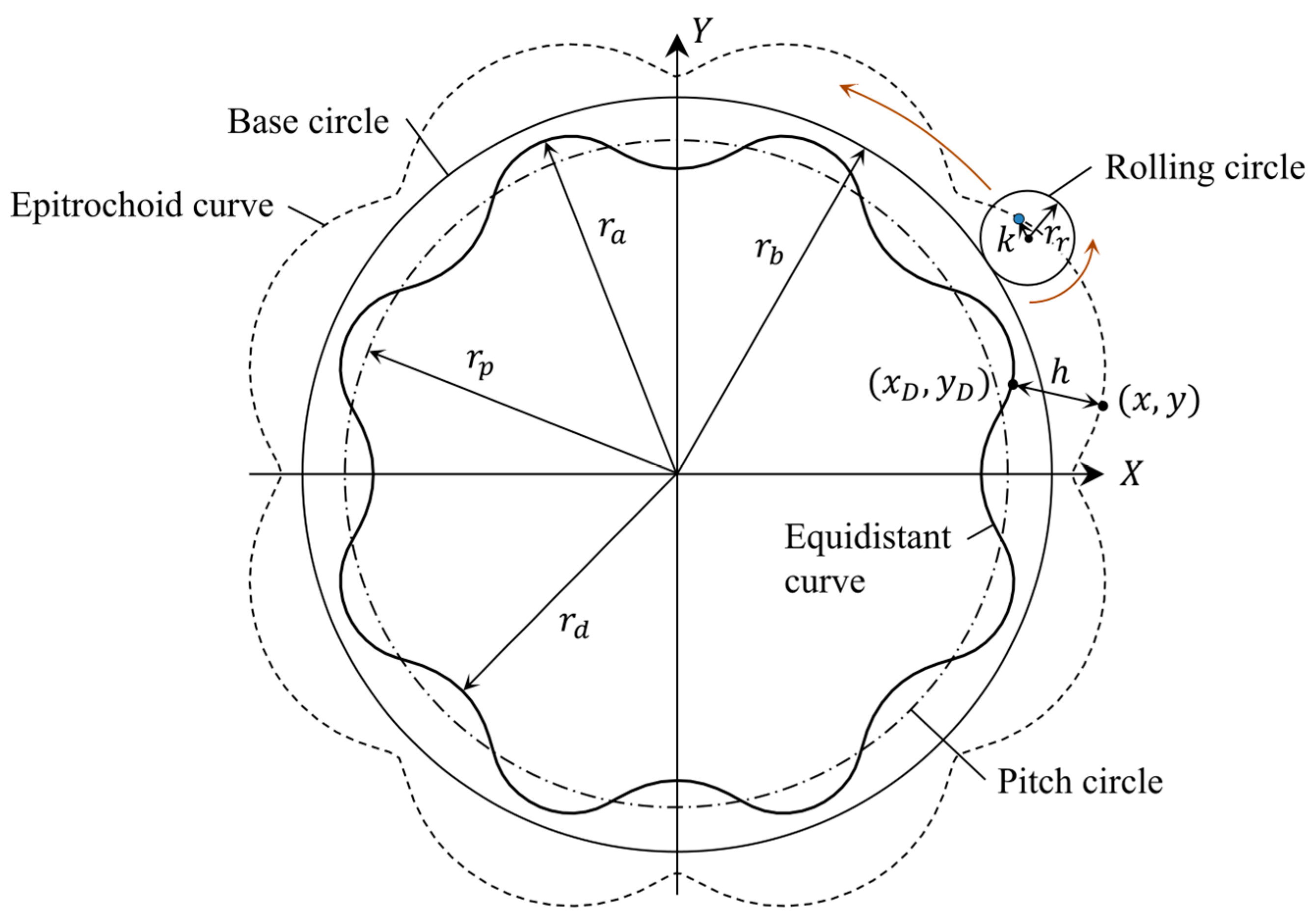
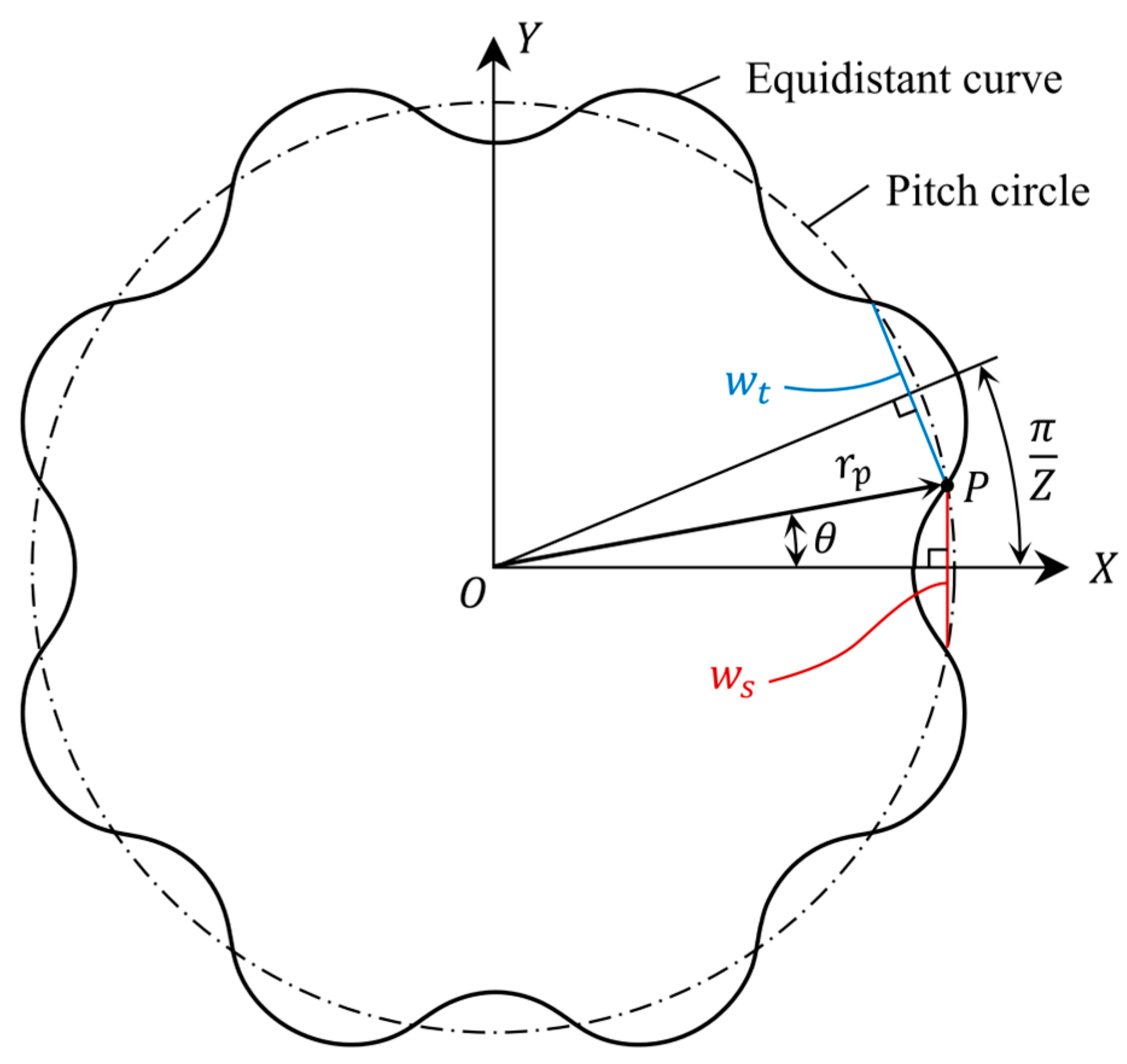
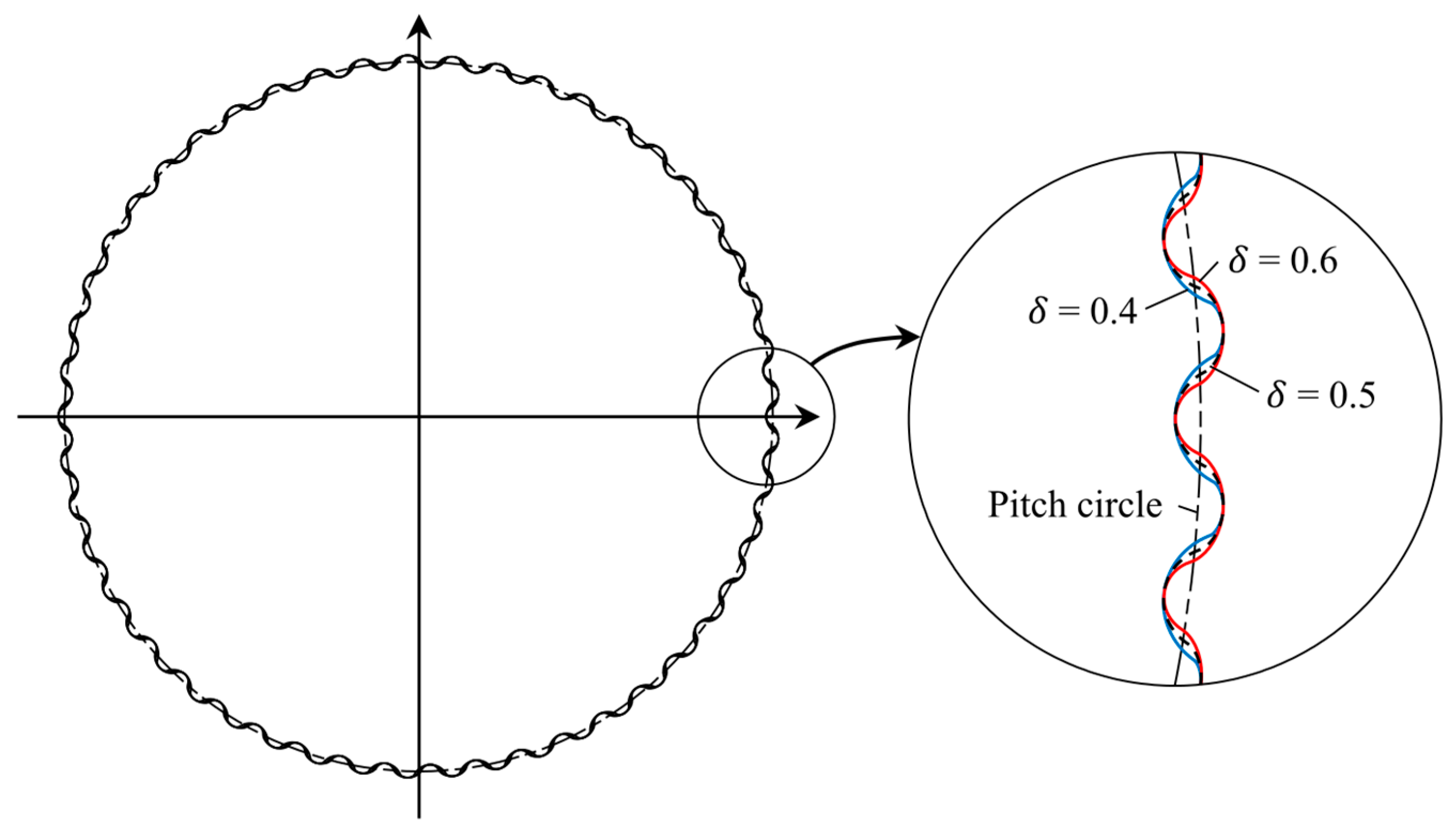
2.1. Generating Cycloidal Tooth Profile
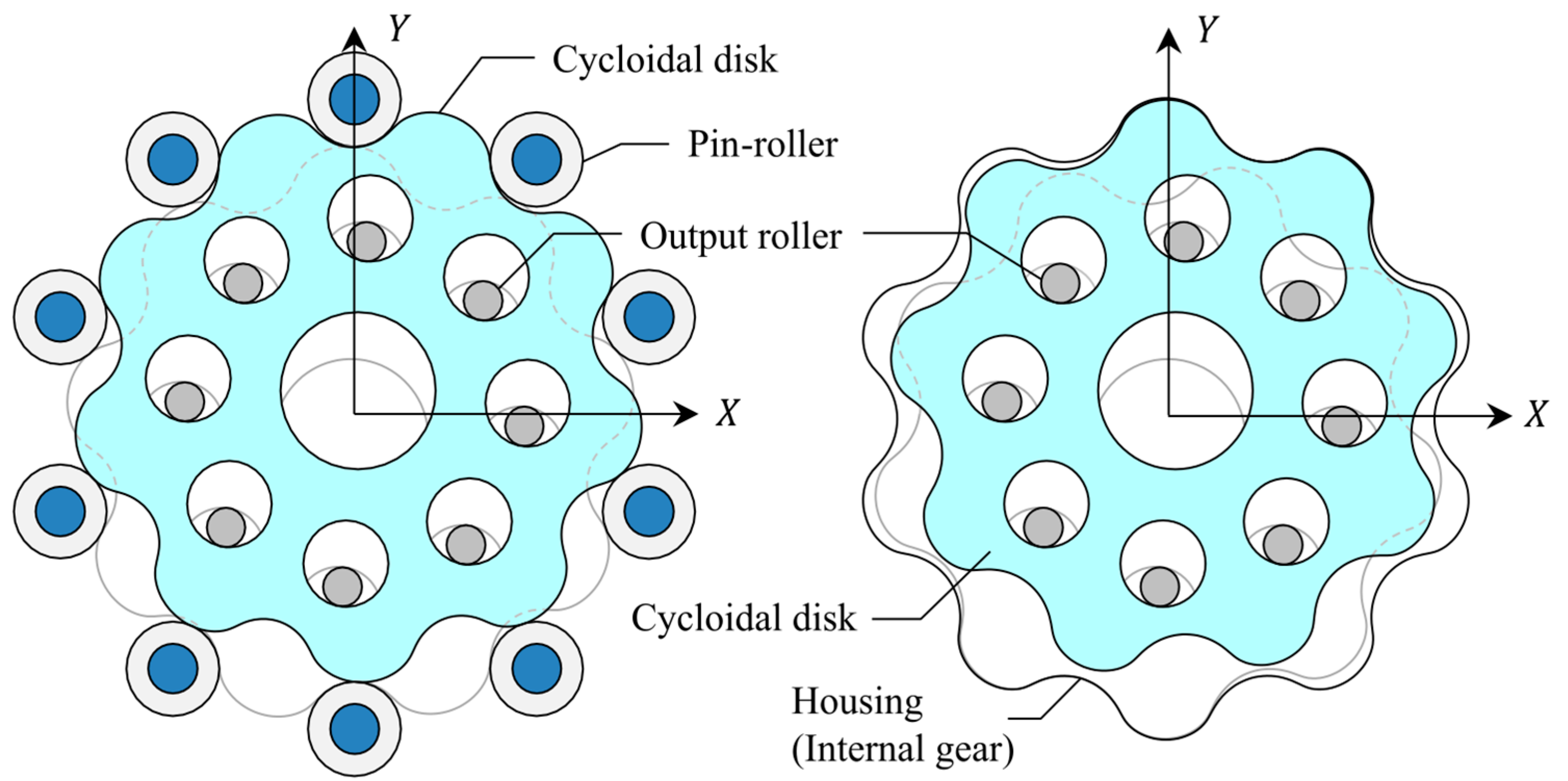
2.2. Design of Cycloidal Reducer
2.3. Power-Assist Device
3. Results
4. Discussions
5. Conclusions
- (1)
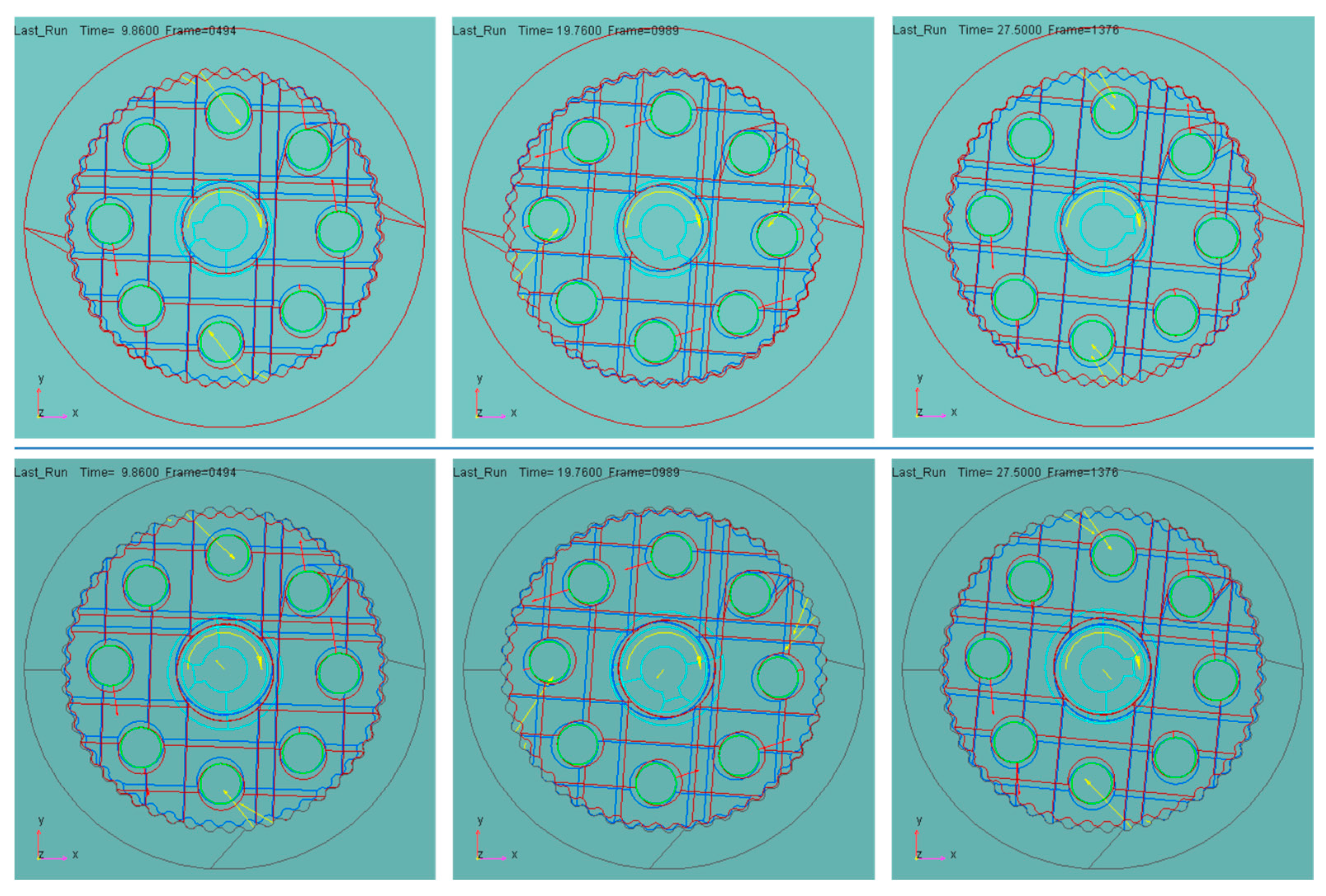
- A cycloidal reducer was designed to develop a PAD that can be used by attaching it to a manual wheelchair. The developed cycloidal reducer does not have a pin wheel, and both housing gear and cycloidal disk are designed in cycloid tooth profile. The cycloidal gear profile can be designed by module, number of lobes, TTR, and eccentricity. In particular, by changing only the TTR, it was possible to design the various gear profiles with the same gear size. The efficiency of the designed cycloidal reducer was 77–78%, the angular transmission accuracy was 14.39 arc min on average, and the backlash was 3.84 arc min.
- (2)
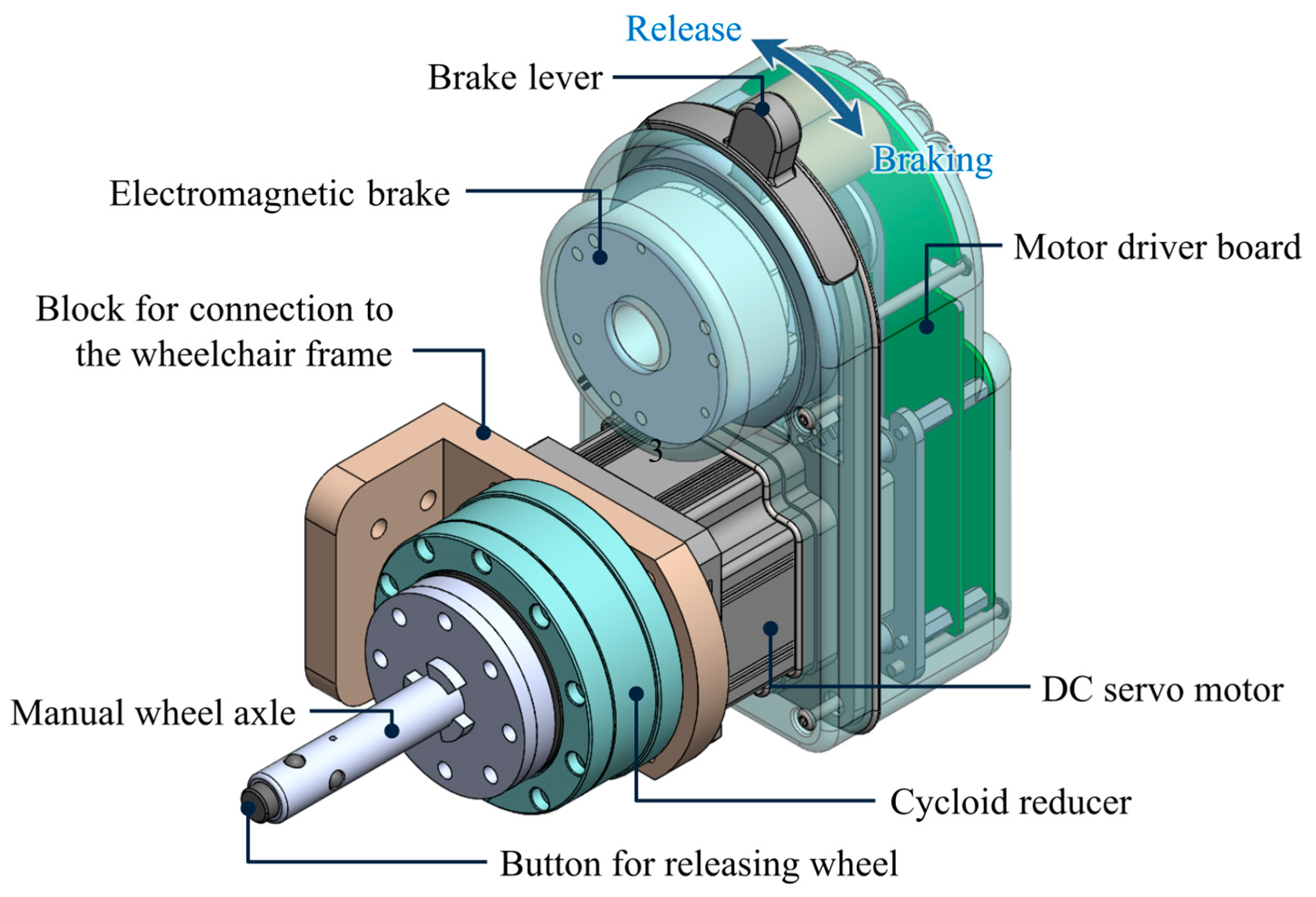
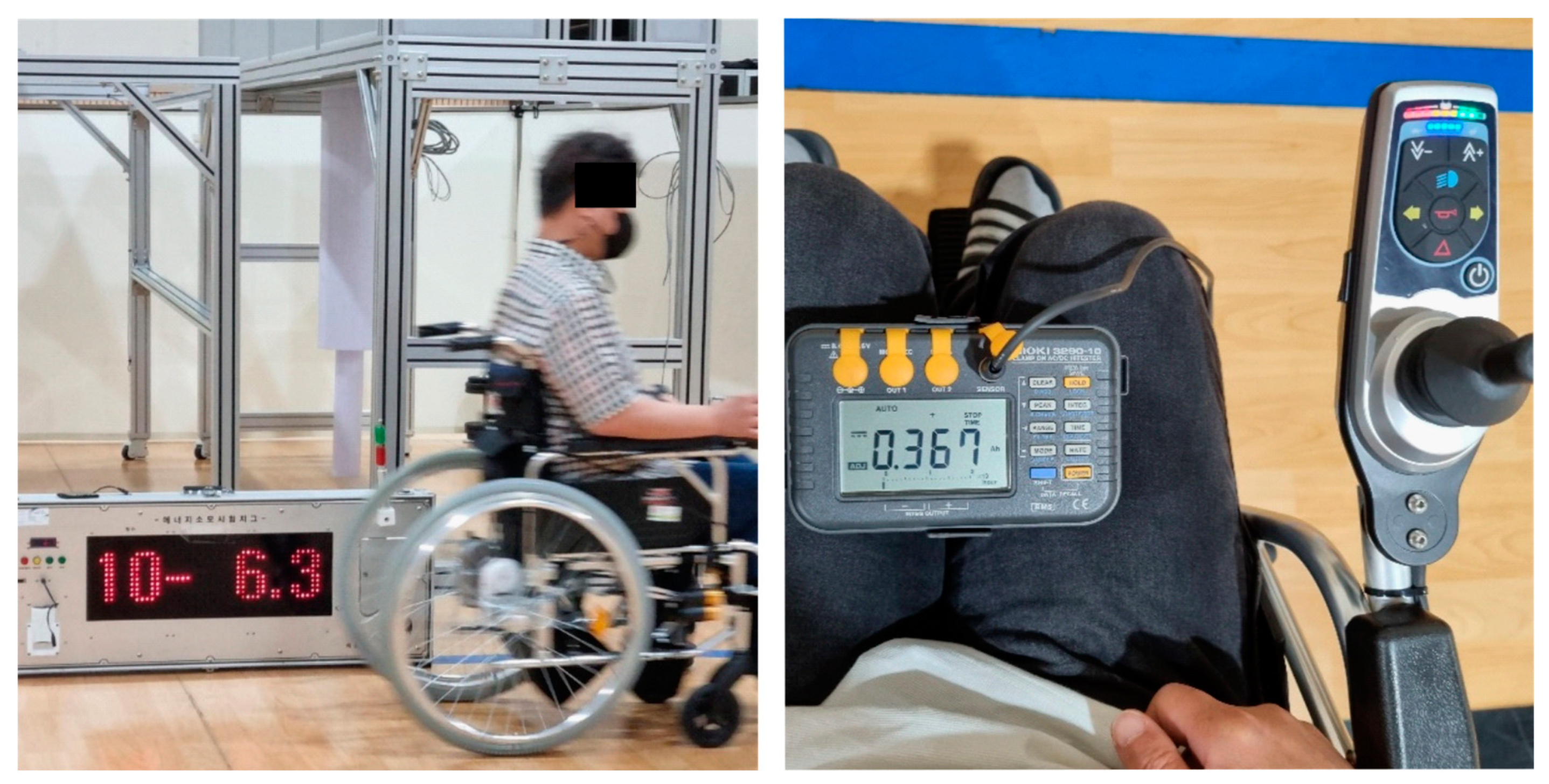
- A cycloidal reducer was installed on a manual wheelchair, and then its potential as a PAD was confirmed through a performance test. The PAD is attached to the manual wheelchair through a connector, and the previously used manual wheel can be used immediately by adding an adapter that can be connected to the PAD. The total weight of the power unit was 2.5 kg, and as a result of the performance test, the maximum speed was 6.3 km/h, the maximum movable distance with full charge was about 22.5 km, and the maximum slope that the wheelchair could ascend was 20%.
Author Contributions
Funding
Institutional Review Board Statement
Informed Consent Statement
Data Availability Statement
Acknowledgments
Conflicts of Interest
References
- Flemmer, C.L.; Flemmer, R.C. A review of manual wheelchairs. Disabil. Rehabil. Assist. Technol. 2016, 11, 177–187. [Google Scholar] [CrossRef] [PubMed]
- Mason, B.; Warner, M.; Briley, S.; Goosey-Tolfrey, V.; Vegter, R. Managing shoulder pain in manual wheelchair users: A scoping review of conservative treatment interventions. Clin. Rehabil. 2020, 34, 741–753. [Google Scholar] [CrossRef] [PubMed]
- Khalili, M.; Eugenio, A.; Wood, A.; Van der Loos, M.; Ben Mortenson, W.; Borisoff, J. Perceptions of power-assist devices: Interviews with manual wheelchair users. Disabil. Rehabil. Assist. Technol. 2021, 27, 1–11. [Google Scholar] [CrossRef] [PubMed]
- Elliott, W.F.; William, C.M.; Jory, A.C.; Johanne, L.M.; Jaimie, F.B. Evaluation of two power assist system for manual wheelchairs for usability, performance and mobility; a pilot study. Disabil. Rehabil. Assist. Technol. 2021, 22, 1–13. [Google Scholar]
- U.S. Department of Veterans Affairs, Clinical Limits of Use Tool (CLOUT) for Wheeled Mobility Devices; U.S. Department of Veterans Affairs: Washington, DC, USA, 2018.
- Emelie, B.F.; Inka, L. Effects of the SmartDrive on mobility, activity, and shoulder pain among manual wheelchair users with spinal cord injury-a prospective long-term cohort pilot study. Disabil. Rehabil. Assist. Technol. 2022, 5, 1–10. [Google Scholar]
- Alber GmbH. SMOOV. Available online: https://smoov.com/us-en/smoov-one/ (accessed on 23 September 2022).
- Alber GmbH. E-Fix. Available online: https://www.alber.de/en/products/add-ondrive/e-fix/ (accessed on 23 September 2022).
- Seong, H.H.; Youm, K.W. Development of Electric Motion Wheel Chair Driving System using Planetary Gear Device. Int. J. Adv. Smart Converg. 2020, 9, 199–206. [Google Scholar]
- Bruno, G.; Gary, V.H.; Jerome, I.; Nadine, P.; Nabil, B.; Isabelle, V.; Marjorie, F.; Didier, P.; Frederic, L. Evaluation of 3 pushrim-activated power-assisted wheelchair in patients with spinal cord injury. Arch. Phys. Med. Rehabil. 2015, 96, 894–904. [Google Scholar]
- Sehoon, O.; Kyoungchul, K.; Yoichi, H. Operation state observation and condition recognition for the control of power-assisted wheelchair. Mechatronics 2014, 24, 1101–1111. [Google Scholar]
- Nam, K.T.; Jang, D.J.; Kim, Y.C.; Heo, Y.; Hong, E.P. A Study of a Handrim-Activated Power-Assist Wheelchair Based on a Non-Contact Torque Sensor. Sensors 2016, 16, 1251. [Google Scholar] [CrossRef] [PubMed] [Green Version]
- Sensinger, J.W.; Lipsey, J.H. Cycloid vs. harmonic drives for use in high ratio, single stage robotic transmissions. In Proceedings of the IEEE International Conference on Robotics and Automation, St Paul, MN, USA, 14–18 May 2012; pp. 4131–4135. [Google Scholar]
- Jang, D.J.; Kim, Y.C.; Hong, E.P.; Kim, G.S. Geometry design and dynamic analysis of a modified cycloid reducer with epitrochoid tooth profile. Mech. Mach. Theory 2021, 164, 104399. [Google Scholar] [CrossRef]
- Malhotra, S.K.; Parameswaran, M.A. Analysis of a cycloid speed reduce. Mech. Mach. Theory 1983, 18, 491–499. [Google Scholar] [CrossRef]
- Shin, J.H.; Kwon, S.M. On the lobe profile design in a cycloid reducer using instant velocity center. Mech. Mach. Theory 2006, 41, 596–616. [Google Scholar] [CrossRef]
- Lin, K.S.; Chan, K.Y.; Lee, J.J. Kinematic error analysis and tolerance allocation of cycloidal gear reducers. Mech. Mach. Theory 2018, 124, 73–91. [Google Scholar] [CrossRef]
- Hartmann, E. Geometry and Algorithms for Computer Aided Design; Darmstadt University of Technology: Darmstadt, Germany, 2003; pp. 28–30. [Google Scholar]
- Nakamura, S. Applied Numerical Methods in C; Prentice-Hall International: London, UK, 1993; p. 76. [Google Scholar]
- Panchev, V. Design of A Planetary-Cyclo-Drive Speed Reducer Cycloid Stage, Geometry, Element Analyses. Ph.D. Thesis, Linnaeus University, Växjü, Sweden, 2012. [Google Scholar]
- Lankarani, H.M.; Nikravesh, P.E. A contact force model with hysteresis damping for impact analysis of multibody systems. ASME J. Mech. Des. 1990, 112, 369–376. [Google Scholar] [CrossRef]
- Maiti, R.; Roy, A.K. Minimum tooth difference in internal-external involute gear pair. Mech. Mach. Theory 1996, 31, 475–485. [Google Scholar] [CrossRef]
- Hsieh, C.F. Dynamics analysis of cycloidal speed reducers with pinwheel and nonpinwheel designs. J. Mech. Des. 2014, 136, 091008. [Google Scholar] [CrossRef]
- Levy, R.M.; Nelson, R.; Layer, J. End-user Testing of a Variable Position Mid Wheel Drive Power Wheelchair. In Proceedings of the RESNA Annual Conference, Baltimore, MD, USA, 28 June–3 July 2012. [Google Scholar]


| Parameter | Value | |
|---|---|---|
| Contact between the housing gear and cycloidal disk | Stiffness (N/mm) | 7.0 × 10⁶ |
| Force Exponent | 2.2 | |
| Damping (N·s/mm) | 7.0 × 10⁵ | |
| Penetration Depth (mm) | 0.095 | |
| Contact between the cycloidal disk and output roller | , Stiffness (N/mm) | 6.0 × 10⁶ |
| Force Exponent | 2.2 | |
| Damping (N·s/mm) | 4.0 × 10⁴ | |
| Penetration Depth (mm) | 0.009 |
| Parameter | Cycloidal Disk | Housing Gear |
|---|---|---|
| Results | Results | |
| Module | 1.0 | 1.0 |
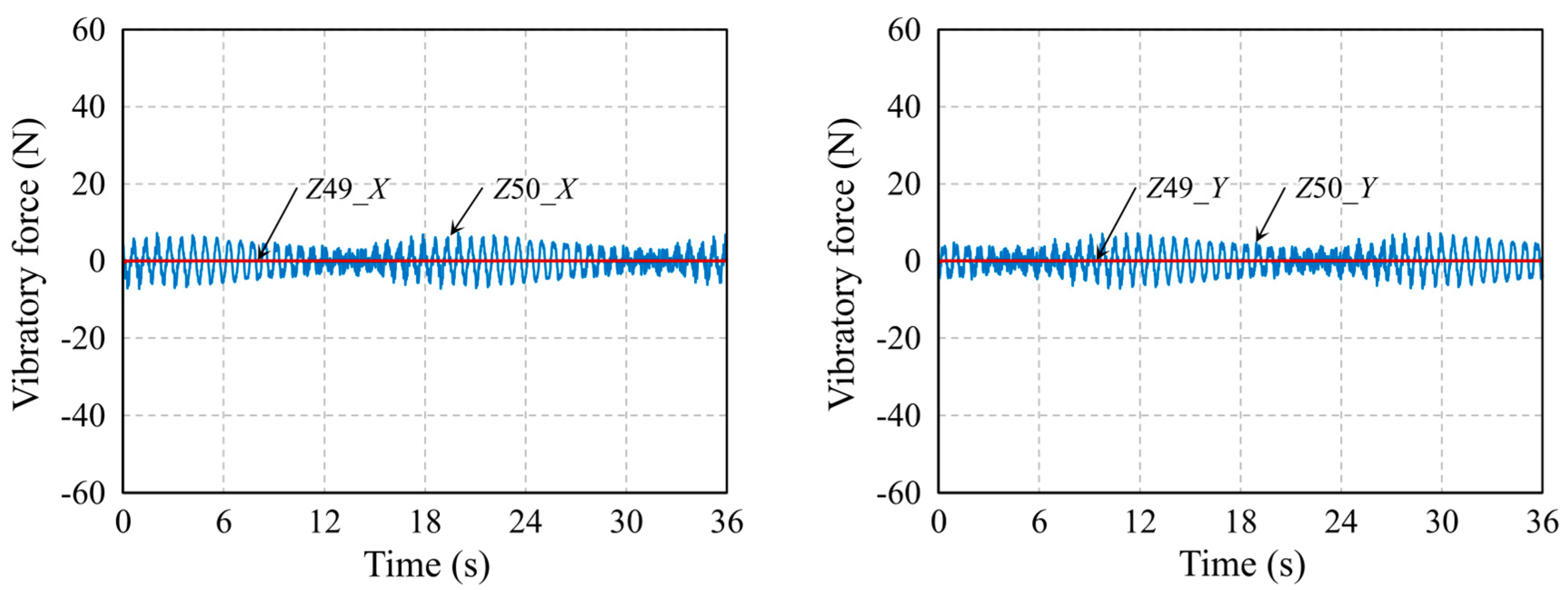
| The number of teeth | 49 | 50 |
| Distance from the center of the rolling circle (mm) | 0.45 | 0.45 |
| Offset distance (mm) | 0.9106 | 0.9104 |
| Tip diameter, dt (mm) | 49.9 | 50.9 |
| Pitch diameter, dp (mm) | 49 | 50 |
| Root diameter, dr (mm) | 48.1 | 49.1 |
| Parameter | Results | |
|---|---|---|
| Efficiency (%) | CW | 77.07 |
| CCW | 78.21 | |
| Angular transmission accuracy (arc min) | CW | 13.27 |
| CCW | 15.51 | |
| Backlash (arc min) | - | 3.84 |
Disclaimer/Publisher’s Note: The statements, opinions and data contained in all publications are solely those of the individual author(s) and contributor(s) and not of MDPI and/or the editor(s). MDPI and/or the editor(s) disclaim responsibility for any injury to people or property resulting from any ideas, methods, instructions or products referred to in the content. |
© 2023 by the authors. Licensee MDPI, Basel, Switzerland. This article is an open access article distributed under the terms and conditions of the Creative Commons Attribution (CC BY) license (https://creativecommons.org/licenses/by/4.0/).
Share and Cite
Jang, D.-J.; Kim, Y.-C.; Hong, E.-P.; Kim, G.-S. Development of Power-Assist Device for a Manual Wheelchair Using Cycloidal Reducer. Appl. Sci. 2023, 13, 954. https://doi.org/10.3390/app13020954
Jang D-J, Kim Y-C, Hong E-P, Kim G-S. Development of Power-Assist Device for a Manual Wheelchair Using Cycloidal Reducer. Applied Sciences. 2023; 13(2):954. https://doi.org/10.3390/app13020954
Chicago/Turabian StyleJang, Dae-Jin, Yong-Cheol Kim, Eung-Pyo Hong, and Gyoo-Suk Kim. 2023. "Development of Power-Assist Device for a Manual Wheelchair Using Cycloidal Reducer" Applied Sciences 13, no. 2: 954. https://doi.org/10.3390/app13020954