Article

U-Net-Embedded Gabor Kernel and Coaxial Correction Methods to Dorsal Hand Vein Image Projection System

1
College of Intelligent Technology and Engineering, Chongqing University of Science & Technology, Chongqing 401331, China
2
College of Electronic and Information Engineering, Southwest University, Chongqing 400715, China
*
Author to whom correspondence should be addressed.
Appl. Sci. 2023, 13(20), 11222; https://doi.org/10.3390/app132011222
Submission received: 23 August 2023 / Revised: 4 October 2023 / Accepted: 10 October 2023 / Published: 12 October 2023
(This article belongs to the Special Issue Innovative Technologies in Image Processing for Robot Vision)

Abstract

:
Vein segmentation and projection correction constitute the core algorithms of an auxiliary venipuncture device, responding to accurate venous positioning to assist puncture and reduce the number of punctures and pain of patients. This paper proposes an improved U-Net for segmenting veins and a coaxial correction for image alignment in the self-built vein projection system. The proposed U-Net is embedded by Gabor convolution kernels in the shallow layers to enhance segmentation accuracy. Additionally, to mitigate the semantic information loss caused by channel reduction, the network model is lightweighted by means of replacing conventional convolutions with inverted residual blocks. During the visualization process, a method that combines coaxial correction and a homography matrix is proposed to address the non-planarity of the dorsal hand in this paper. First, we used a hot mirror to adjust the light paths of both the projector and the camera to be coaxial, and then aligned the projected image with the dorsal hand using a homography matrix. Using this approach, the device requires only a single calibration before use. With the implementation of the improved segmentation method, an accuracy rate of 95.12% is achieved by the dataset. The intersection-over-union ratio between the segmented and original images is reached at 90.07%. The entire segmentation process is completed in 0.09 s, and the largest distance error of vein projection onto the dorsal hand is 0.53 mm. The experiments show that the device has reached practical accuracy and has values of research and application.

1. Introduction

As a routine medical procedure, the success rate of venipuncture is not solely dependent on the medical staff’s skill and experience [1]. Various objective factors can also affect the outcome, such as dark skin, a thick subepidermal fat layer, and poor lighting conditions, all of which can decrease the success rate [2]. Due to their high precision and sensitivity, venipuncture robots [3] are starting to emerge. With the continuous development of technology, the most important vein segmentation algorithm has been continuously updated. Currently, most vein projectors employ near-infrared imaging principles to capture vein images [4]. By using a near-infrared camera, the features of the veins in near-infrared images are more distinct compared to those appearing blue-green under natural light. The obtained image is transmitted to a processor for enhancement and segmentation processing. Finally, the segmented binary image is fed back to the dorsal of the hand by the projector, allowing the medical staff to perform vein puncture through the projected image. Regarding the entire hand vein imaging process, this paper makes improvements to the vein segmentation and projection correction algorithms. Furthermore, a system is developed to validate the method, yielding a better result.
Since the development of the first assisted vein puncture device [5], there has been an increasing demand for accuracy in projection results. Usually, the obtained NIR images are accompanied by severe noise, because veins are hidden underneath the skin and fat and the NIR light penetrates the skin to a limited depth. Although the pixel’s brightness in the vein and dorsal is different, the overall contrast of the image is low, and the edges of the veins are often blurry [6]. Furthermore, the camera and projector are not located in the same position, resulting in a misalignment of the projected image with the dorsal hand. Therefore, this paper investigates two critical techniques in vein projector technology: image segmentation and projection correction. For the image segmentation problem, the core idea of the traditional methods is to design a feature extractor. However, the extractor requires the manual setting of certain parameters, which may not be suitable for different application scenarios. Additionally, manually designed feature extractors may fail to capture complex image features, resulting in poor segmentation accuracy and low robustness. Subsequently, regarding projection correction algorithms, most of the existing methods align the projected image with the dorsal by using the homography matrix. However, the hand has a larger curvature towards the edges, resulting in less accurate projection results. Furthermore, as the supporting surface, the hand is not fixed, therefore, any change in its position will lead to changes in the homography matrix [7].
To address these issues, this paper utilizes corresponding solutions, which are also the main contributions, as follows:
(1)
The prior knowledge of Gabor kernels is integrated into U-Net to improve the network. Through the embedding of the Gabor kernel into the neural network, the feature extraction capability of the shallow network is enhanced. Consequently, this leads to improved accuracy in image segmentation and lays a foundation for later precise projection.
(2)
The proposed U-Net achieves a lightweight design by replacing conventional convolutions with inverted residual blocks. This operation mitigates the semantic information loss caused by channel reduction, while decreasing the parameter size, and is suitable for real-time projection.
(3)
During the projection process, this paper proposes a method that combines coaxial correction with the homography matrix. This approach enables the device to require only a single calibration before use. It enhances the accuracy of the vein projection system and simplifies the process of projection correction.
(4)
To validate the improved algorithm, we have established a database, created corresponding labels manually, and constructed a dorsal hand vein projection system. The proposed methods for vein segmentation and projection have been trained and tested using the dataset. The accuracy of both segmentation and projection, along with the response time, meets the requirements of the application.
The rest of this survey is structured as follows: Section 2 presents the research background of the image segmentation algorithm and projection correction algorithm. In Section 3, the modules of the imaging system are presented, along with the principles of the relevant algorithms used in this paper. Section 4 discusses the rationale behind the parameter selection in the related algorithms, showcasing the ultimate experimental outcomes. Lastly, Section 5 summarizes the proposed algorithm, while delving into an analysis of the prevailing errors, elucidating the research trends and potential areas for improvement.

2. Related Research

The vein segmentation algorithm and the projection correction algorithm are two crucial technologies in auxiliary venipuncture devices. The former involves extracting vessels from dorsal hand images, while the latter addresses the issue of inaccurate projection caused by different equipment angles. In the field of image segmentation, Tong Liu [8] proposed an improved repeated line tracking algorithm for finger vein image segmentation in 2013. The algorithm utilizes vein width in the image to determine the parameters, then uses the improved repeated line tracking method to find the locus space of the finger vein. Finally, the Otsu method is applied to extract the finger vein. To distinguish the vein region on the dorsal part of the hand from the non-vein region, Zhang J. [9] utilized the kernel fuzzy C-means (KFCM) algorithm for initialization. Furthermore, they designed a defogging algorithm and an edge-fitting term to improve the segmentation process, ultimately achieving better results. In 2012, with the ascent of convolutional networks, artificial intelligence [10] has experienced rapid growth and advancement, and it has gradually found its way into various aspects of human life. Long J. [11] proposed an end-to-end fully convolutional network to handle image segmentation tasks in 2015. The approach utilized various classification networks for downsampling and ultimately yielded precise segmentation results. In the same year, Olaf Ronneberger et al. [12] proposed a U-Net for image segmentation. The U-Net consists of an encoder–decoder architecture that combines low- and high-level information, making it suitable for the precise segmentation of medical images. M. Liu et al. [13] proposed a deep convolutional neural network architecture with nested U-Net by combining global and local loss information to optimize the network, achieving better segmentation results. In 2021, T. He et al. [14] used U-Net with an attention mechanism for dorsal hand vein image segmentation. The algorithm highlighted the feature that had a significant impact on the results and utilized a jump-connected structure for multi-scale feature recognition, thereby enhancing the accuracy of segmentation. The traditional image segmentation methods have limitations in practical applications, which can be greatly affected by grayscale distribution, and are poor at handling noise. Compared with the traditional methods, neural networks can artificially divide the image contours to make labels [15] and specify the features to be extracted [16]. This approach can better handle noise, lighting variations, and other factors, making the neural networks more robust than the traditional methods. In this paper, we propose an approach to image segmentation using neural networks. Specifically, we improve the structure of existing segmentation networks and reduce the parameters for network training, while ensuring segmentation accuracy.
Currently, although projection correction algorithms have yielded relatively good results, their application still has some shortcomings. The first venous projector was invented by American medical engineer Zeman [5] in 2004. It utilizes a hot mirror to adjust the optical path of the camera and projector to coaxial, eliminating the influence of curved projection and enabling the projected image to coincide with the object. However, this method presents challenges in the precision requirements for the equipment, and coaxial optical path alignment is difficult to achieve. In 2013, Dai X. [17] designed a venous projector that treats the dorsum of the patient’s hand as a planar surface with four labeled points. The projection image is adjusted through a perspective transformation so that the four points in the projection image align with the four points labeled on the hand, facilitating accurate projection onto the dorsum of hand. However, this method requires the calibration of the four points before each venipuncture, which is cumbersome. In 2016, Gan Q. et al. [18] developed a projection navigation system that captures images at a rate of 60 frames per second. The projected image is calibrated through perspective transformation to guide the surgeon during the operation. In 2017, Tran Van Tien [19] used near-infrared light as the light source and fed the near-infrared image into a camera through the reflective function of a beamsplitter. After passing through a median filter to reduce noise and undergoing Otsu segmentation, the near-infrared image is transmitted to a projector, and ultimately projected onto the patient’s dorsum of the hand. However, this method is limited by the high precision requirements of the instrument, as well as the information loss when the light passes through the beamsplitter. Hia Yee May [20] proposed a system for the real-time visualization of veins based on near-infrared imaging, which displays the vein images in real-time on the monitoring screen. However, the method does not project the segmented image on the dorsum of hand; moreover, this method also lacks an effective design for the projection method. Markus Funk [21] proposed an in situ projection-based prompter to assist workers with cognitive impairments. The product’s location is obtained through a depth camera, and a homography matrix is used to project the related information onto the product. In 2018, Gunawa I. [22,23] proposed a method for adjusting images using a distance sensor. After augmenting the acquired near-infrared images, the distance sensor is utilized to obtain the real-time distance from the hand’s dorsum to the camera. With this distance, the projected image is finely tuned to synchronize with the object. This approach addresses the issue of changes in the homography matrix due to the hand’s position change. Another method proposed by Liu P [24] uses fluorescence imaging with indocyanine green (ICG). After adjusting the optical paths of the camera and the projector to coaxial, the images are projected back to the surgical site in real time. Additionally, Li C. [25] proposed a handheld projection device. In this device, the optical path of the camera runs parallel to that of the projector. After cropping the non-overlapping areas of the projector and the camera, the projected image is calibrated, and the medical staff are guided during surgery based on the overlapping area image.

3. Materials and Methods

To validate the improved algorithms, this we devised a vein projection system composed of the following three modules: an image acquisition module, an image processing module, and a projection module. In the image acquisition module, we designed a uniformly distributed near-infrared (NIR) light source by using a light-guide plate. This design effectively reduces the impact of reflected flares on the images. The captured near-infrared images are transmitted to the image processing module, where they are enhanced and segmented by the improved U-Net algorithm. Finally, the light path of the projector and the NIR camera are corrected to be coaxial. Even if there is an error in the installation process that causes the light path of the two to be not completely coaxial, the projected image can also be adjusted to coincide with the real object through a homography matrix. Figure 1 depicts the physical components of the vein projector and illustrates each module in detail.
During the experiment, we employed four 850 nm LED chips as light sources, each with an optical power of 60 mW. We connected them in parallel to a 3.3 V power supply and measured a working current of 50 mA. These four LED chips were embedded into a 5 × 5 cm acrylic light-guide plate to generate uniform near-infrared light. To capture the images, we utilized a near-infrared camera module manufactured by LRCP Luoke (produced in Shenzhen, China), with the model designation V1080P_PCBA. This camera boasts a maximum resolution of 1920 × 1080 pixels, as detailed in Table 1. In the process of capturing images, we set the image size to 192 × 192 pixels based on the proportion of the hand’s area within the camera’s captured frame. With regard to the projection module, we utilized a miniature projector with the model name “m100smart,” manufactured by Vmai (produced in Shenzhen, China). This device achieved wireless connectivity with the image processing module via Parsec (150-89d) software, and the specific parameters can be viewed in Table 2. The image processing module was configured with an AMD Ryzen 7 5800H and 16 GB of RAM to ensure high performance. We used a hot mirror with an incidence angle of 45°, which had a strong reflection ability for near-infrared light, with wavelengths ranging from 750 nm to 1200 nm. Additionally, this mirror allowed the light outside of this range to pass through directly. The transmission rate and light wavelength relationship can be seen in Figure 2. To ensure stability and precision, we fixed the camera and hot mirror within a 3D-printed box.

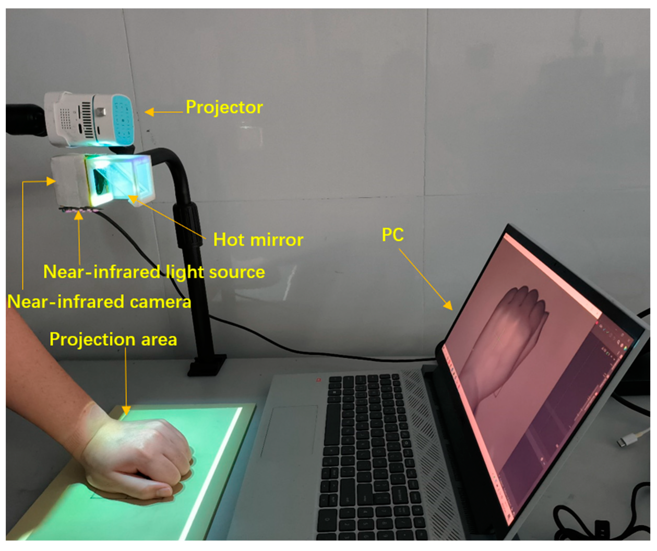
3.1. Image Acquisition

To acquire clear near-infrared images, we utilized 850 nm near-infrared light as the source. The light-emitting diodes are embedded within a light-guide plate to emit uniformly distributed near-infrared light. After NIR light is applied to the dorsal hand for venography, the imaging results are captured by a near-infrared camera after being reflected by a hot mirror. A narrowband filter with a wavelength of 850 nm is installed in front of the camera, greatly minimizing the impact from visible light. Finally, the obtained image is transmitted to the processor for subsequent processing.

3.2. Lightweight U-Net Model Design with Embedded Gabor Kernel

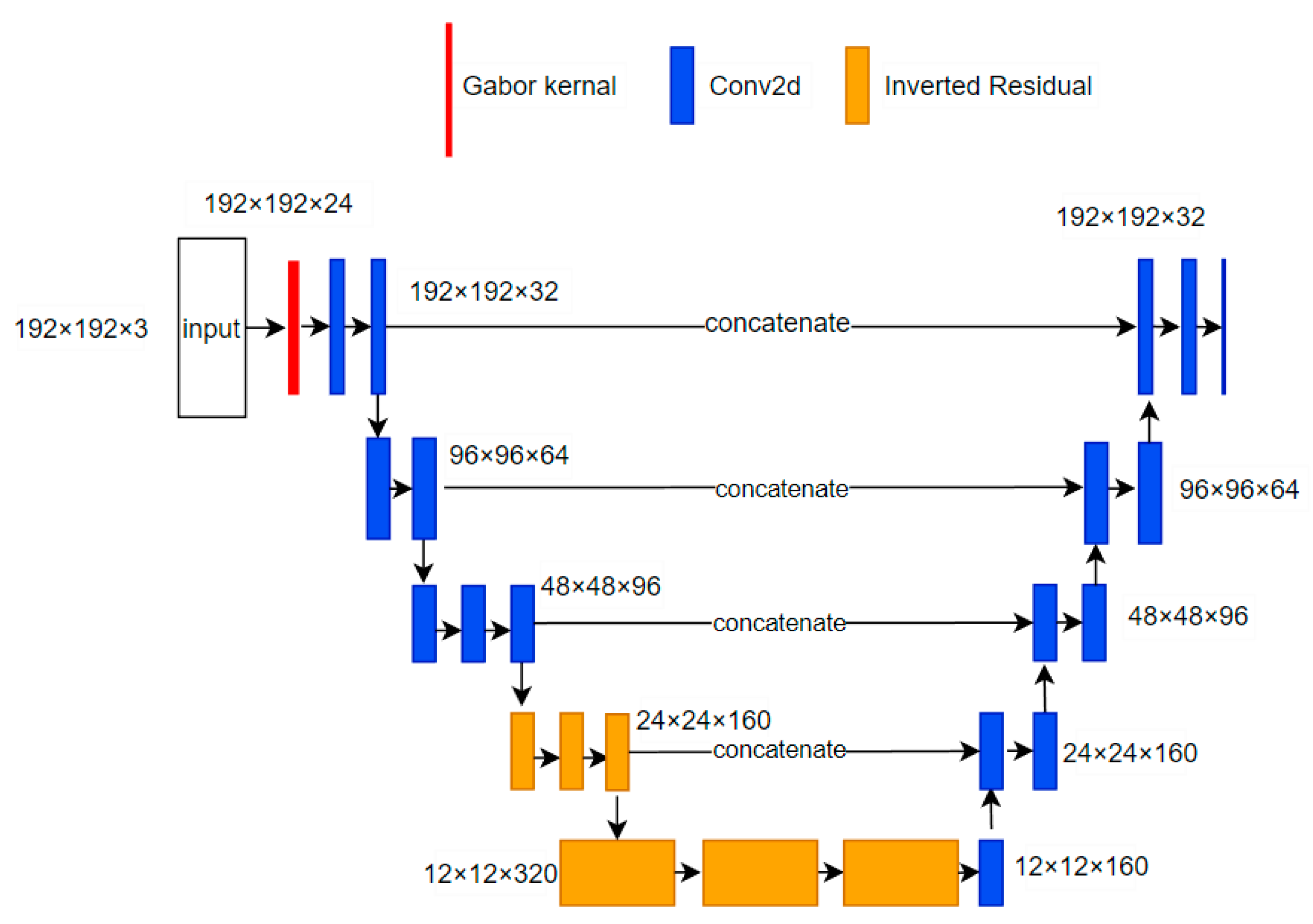
3.2.1. Improved U-Net Architecture

The acquired image is subjected to binarization segmentation in the image processing module. We embedded prior knowledge into the segmentation network, fully utilizing the texture enhancement effect of Gabor filtering [26] to bolster the features in the shallow network. Specifically, we employ the U-Net for the segmentation network, which incorporates the multi-directional and multi-scale Gabor filter parameters into the encoder’s shallow convolution kernels. This integration is shown in the red section of the network model depicted in Figure 3. After adjusting the overall channel number of the downsampling network, the convolutional operations are substituted with inverted residual blocks to minimize the semantic information loss, as depicted by the yellow segment of the network model. The improved U-Net’s structure is shown in Figure 3.

3.2.2. Embedding of Gabor Prior Knowledge

The two-dimensional Gabor filter shares some similarities with the biological visual system, such as its response to visual signals of varying directions and frequencies. Therefore, Gabor filters exhibit a favorable performance in simulating the characteristics of the biological visual system. The image processed by its kernel function is highly similar to what is observed by higher animals [27]. Using the Gabor filter as a bandpass filter can eliminate noise while preserving the true structure information of ridges and valleys. Additionally, some trained shallow convolutional kernels in the neural network are similar to the Gabor filter [28,29]. In order to extract richer image features, we embedded a Gabor layer in the first layer of the network. The Gabor kernel function is given by the following formula:
G a b o r = e x p x 2 + γ 2 2 y 2 2 σ 2 e x p i 2 π x λ + ψ
x = x c o s θ + y s i n θ
y = x s i n θ + y c o s θ
In this context, “i” denotes the imaginary unit, “ψ” signifies the phase parameter of the cosine function in the Gabor kernel, “θ” represents the orientation of the parallel stripes in the Gabor filter kernel, “λ” stands for the frequency of the grayscale variation in the image, and “σ” denotes the standard deviation of the Gaussian factor in the Gabor function, which is related to “λ”, as follows:
σ λ = 1 π l n 2 2 2 b + 1 2 b 1
The DC component represents the mean brightness value of the image and does not contain any frequency information. Removing the DC component in a Gabor filter can effectively reduce the influence of illumination or image background brightness. In the near-infrared light spectrum, there is little difference in the absorption rate of near-infrared light between the vein region and the non-vein regions, resulting in severe contrast degradation and blurred vein edges. In the image, the non-vein area acting as the background is relatively large. Subtracting the DC component is equivalent to performing a differential operation on the background, which enhances the image contrast and makes the vein texture more prominent. As for filters, it is best to keep the mean at 0 to maintain the original image intensity. We embedded the Gabor filter without the DC component as a convolution kernel in the shallow network, enhancing the features of the image and helping the deeper network to extract semantic information [30]. The formula for the Gabor convolution kernel without a DC component is as follows:
G a b o r = e x p π x 2 + γ 2 2 y 2 2 σ 2 e x p i 2 π x λ + ψ exp π σ 2 λ 2 + i ψ

3.2.3. Lightweight Design of U-Net

In the course of downsampling in U-Net, different backbone networks may be employed as encoders, among which VGG16 is considered to be an exceptional model for feature extraction [31]. However, despite its efficacy in feature extraction, the VGG16 network’s abundant channels may lead to an excessive number of parameters. It is necessary to reduce the network’s weight while preserving its capacity for accurate image segmentation.
In this paper, the channel numbers of each network layer have been reduced to decrease the number of parameters. However, reducing the channel numbers may lead to information loss, therefore, we adopted the inverted residual block instead of the convolution method to mitigate this issue during downsampling. Unlike the residual block, the inverted residual block has a small head and a large middle structure. The ReLU activation function may cause a significant loss of low-dimensional feature information [32], therefore, the inverted residual block increases the dimension of the feature map before applying the ReLU activation function, thereby reducing information loss. The structure of the inverted residual block and residual block [33] are shown in Figure 4, respectively.
The inverted residual block effectively addresses the issues of gradient disappearance and information loss. However, it is also more complex compared to the regular convolutional structure, which also elevates the computational burden on the model. The essence of this venous segmentation is semantic segmentation [34], and the processing of semantic information is mainly concentrated in the deep network. Hence, to minimize the loss of semantic information and reduce the processing time caused by complex structures, we exclusively employed an inverted residual block in the last two blocks to substitute regular convolutions. This approach ensures that the model maintains its non-linear expressive capability while not increasing the image segmentation time.

3.3. Coaxial Alignment Correction Algorithm Based on Optical Path

3.3.1. Coaxial Alignment of Optical Path

To align the projected image with the actual object, this paper proposes a method that combines coaxial correction and a homography matrix. Through the adjustment of the optical path to mitigate the influence of the curved surface projection and employing the homography matrix to refine the projected image, the resulting image is then perfectly aligned with the actual object.
The process of capturing images with a camera involves transforming the object from a world coordinate system to a pixel coordinate system, while the process of projection involves moving the image on a pixel coordinate system to a world coordinate system. Therefore, a projector can be viewed as an inverse camera [35]. To ensure that the projected image aligns perfectly with the object, the image in the inverse camera should be the same as the image captured by camera. According to Zhang’s camera calibration method, the image captured by the camera is essentially a projection of a three-dimensional object onto a two-dimensional plane.
When a camera and an inverse camera observe the same surface, the smaller the angle between their optical paths, the smaller the discrepancy in the acquired surface information. When the optical paths of the two devices coincide, it is equivalent to the projector and the camera being in the same position. The image projected onto the surface is precisely the image captured by the camera, and the impact caused by the projection on the curved surface is also reduced. Then, a string of letters is printed on an A4 piece of paper and attached to a bucket-shaped surface, and the images captured by the camera from angles A and B are shown in Figure 5.
From the above figure, it can be observed that, due to the difference in position, the camera captures less information on the left side at angle B. Therefore, to reduce the impact of surface projection and minimize information loss, it is necessary to align the optical paths of both the camera and the projector. By using the properties of the hot mirror, the near-infrared image can be reflected into the camera. Subsequently, the image is transmitted to the projector and projected as visible light, shining onto the dorsal hand through the hot mirror, as illustrated in Figure 6.

3.3.2. Homography Matrix Calibration

During the installation and movement of the device, errors are easily generated. Therefore, adjusting the light path of the camera and projector using a hot mirror often results in an optical path near alignment, but not coaxial. Although the error caused by the surface projection can be reduced, the non-coaxial light path still results in a slight deviation between the projected image and the actual object. To address this issue, we utilized a plane with a printed grid pattern and homography matrix to calibrate the projection. The formula for the homography matrix is as follows:
x 2 y 2 z 2 = h 1 h 2 h 3 h 4 h 5 h 6 h 7 h 8 1 x 1 y 1 z 1
The homography matrix is a mathematical tool used to describe the relationship between two planar transformations. By identifying four non-collinear corresponding points between the two planes, both linear and non-linear transformations can be applied to the image. However, the projected image cannot be observed by the near-infrared camera, and the four corners of the projection need to be manually marked on the flat surface. By using a NIR camera, the positions of the four corners on a flat surface and a projected image can be obtained. Subsequently, the homography matrix is computed as follows:
1.09 1.62 × 10 2 7.92 × 10 3.03 × 10 2 1.07 5.05 × 10 3.72 × 10 5 1.86 × 10 5 1
The Frobenius norm of the homography matrix can be used to measure the size or scale of the matrix and is calculated to be 93.96. This value is used to quantify the deviation between the projected image and the object and assess the discrepancy between them. Then, the homography matrix is used to adjust the projected image to match the object. Images before and after adjustment are shown in Figure 7.

4. Experiment and Discussion

4.1. Image Segmentation

4.1.1. Comparison with and without DC Component

In this paper, we embedded fixed-parameter Gabor filters into shallow networks to enhance image features. This approach effectively alleviates the problem of semantic recognition difficulty in deep networks caused by insufficiently extracted features from shallow networks. Usually, ψ and γ are fixed at 0 and 1, respectively. To make a filter closest to that of an animal’s vision system, the half-response spatial frequency bandwidth is usually set to 1. The value of λ is determined by the width of the veins in the image [36] and can be used to calculate the value of σ. Based on the vein features in the image, we created three different scales and eight different orientations of filters. By removing the DC component in the filter, the impact of lighting and image gray distribution is reduced, resulting in a frequency and directional visual representation closer to that of human perception. In order to better observe the results, we applied Gabor filters both with and without DC components to process the near-infrared images of the dorsal hand. The original image and the filtered images both with and without DC components are shown in Figure 8. It can be observed that the input image has better results after the Gabor filtering process without the DC component.

4.1.2. Comparison of Image Segmentation Results

In order to train the neural network with the gathered images, it is imperative to generate suitable labels for the dataset. First, we must select different thresholds for each image to make coarse binary images. Then, the binary images are used as a mask for manually segmenting the veins, removing the veins that are too thin to be injected. The labels can be viewed in Figure 9.
Then, we place the dataset and the labels in the network to train it and observe the impact of the Gabor kernel on the segmentation results. In this paper, we have conducted experiments using a network with Gabor kernels, Sobel kernels, and no kernels, respectively. The obtained segmentation results are shown in Table 3. It can be observed that embedding Gabor kernels in the shallow convolutional networks significantly improves the segmentation results.
In order to assess the performance of the improved network, comparative experiments were carried out using VGG16, Res-UNet, Dense-UNet, MobileNetv2 [37], and the proposed approach. Before conducting the experiment, a total of 108 dorsal hand vein images were collected, and, after simple data augmentation, they were divided into 432 training samples, 54 validation samples, and 54 test samples. The model was trained with a batch size of 4 for 200 epochs, and the loss functions for each model are shown in Figure 10. After training completion, the test dataset was fed into the neural network for segmentation. Each network model was trained five times. The average accuracy, size, and time taken for image segmentation by the different networks were recorded, as shown in Table 4.
From the table above, it can be observed that, whether the IOU value or precision is used as the standard, the proposed method requires less time and takes up a smaller storage space, while preserving the segmentation efficacy. The segmented results are shown in Figure 11. By examining the disparity between the segmented result and the labels, it is discernible that the error mainly exists at the ends of veins or at the connection points of two comparatively slender veins, which do not fall within the designated area for venipuncture.

4.2. Results of Projection Correction

In this paper, we propose an improvement to the existing method by using a hot mirror to adjust the optical path, which reduces the effect caused by curved projection. This is followed by an adjustment of the projection using a homography matrix, which reduces the requirement of the optical path coaxial to the experimental environment, and accurately projects the image onto the dorsal of the hand. We placed the hand on planes located at different distances from the camera to obtain the results. The images captured by the near-infrared camera and the pre-segmentation and post-segmentation images observed by the human eye are displayed in Figure 12.
The above images show that the projection performs well both in the center and the edge of the back of the hand and manifests no distortion caused by the curved surface. The projected binary vein image is consistent with the actual blood vessel. Although the homography matrix may alter with the plane’s position, due to the prior proximal adjustment of the camera and projector’s optical paths, the homography matrix will not change significantly.
As can be seen from Table 5, the offset errors of the projection in the different planes are within 1 mm, with the maximum average error being 0.53 mm. Considering that the width of the venous blood is typically around 3–4 mm, these errors can be considered negligible.

5. Conclusions

Inspired by U-Net, in this article we have adjusted the structure of the encoder; however, there is still room for improvement in the design of the image segmentation model. The experiments herein demonstrate that increasing the number of layers in the network has little impact on the segmentation results. Therefore, in the future, research can be conducted to lighten the network, coupled with specific network structures to reduce the parameter quantity and mitigate information loss. For projection correction, we used a hot mirror and a homography matrix to adjust the projection results, obtaining accurate results while reducing the precision requirements of the experimental environment. During the use of homography matrix correction, although the influence of hand position changes in the homography matrix has been reduced, there is still room for optimization in this method. When the distance between the plane and the camera changes, the non-linear transformation of the projected image far exceeds the linear transformation it undergoes. Therefore, by altering the distance and recording the position of the projector’s focal point, it becomes feasible to establish a functional relationship between the two. When using the device, the distance can be obtained through binocular cameras or other devices, and, based on the fitted function, the projection can be adjusted accordingly.

Author Contributions

Conceptualization, L.C. and M.L.; methodology, L.C. and M.L.; software, M.L. and J.C.; validation, J.C. and Z.G.; formal analysis, L.C. and Z.L.; data curation, J.C. and Z.G.; writing—original draft preparation, M.L.; writing—review and editing, L.C. and M.L.; supervision, L.C. and Z.L. All authors have read and agreed to the published version of the manuscript.

Funding

This research in this paper is supported by the following funds: (1) The Natural Science Foundation of Chongqing, No. cstc2020jcyj-msxmX0818, cstc2021ycjh-bgzxm0071, and CSTB2023NSCQ-MSX0760; (2) The Science Technology Research Program of Chongqing Municipal Education Commission, No. KJQN201901530, No. KJZD-M202301502, and Chongqing postgraduate education ‘curriculum ideological and political’ demonstration project, No. YKCSZ23193; and (3) The Graduate Innovation Program Project of Chongqing University of Science and Technology, No. YKJCX2220803, No. ZNYKJCX2022008, and No. ZNYKJCX2022017.

Institutional Review Board Statement

Not applicable.

Informed Consent Statement

Not applicable.

Data Availability Statement

Not applicable.

Conflicts of Interest

The authors declare no conflict of interest.

References

  1. Indarwati, F.; Munday, J.; Keogh, S. Nurse knowledge and confidence on peripheral intravenous catheter insertion and maintenance in pediatric patients: A multicentre cross-sectional study. J. Pediatr. Nurs. 2022, 62, 10–16. [Google Scholar] [CrossRef] [PubMed]
  2. Jacobson, A.F.; Winslow, E.H. Variables influencing intravenous catheter insertion difficulty and failure: An analysis of 339 intravenous catheter insertions. Heart Lung 2005, 34, 345–359. [Google Scholar] [CrossRef]
  3. He, T.; Guo, C.; Liu, H.; Jiang, L. Research on Robotic Humanoid Venipuncture Method Based on Biomechanical Model. J. Intell. Robot. Syst. 2022, 106, 31. [Google Scholar] [CrossRef] [PubMed]
  4. Sakudo, A. Near-infrared spectroscopy for medical applications: Current status and future perspectives. Clin. Chim. Acta 2016, 455, 181–188. [Google Scholar] [CrossRef] [PubMed]
  5. Zeman, H.D.; Lovhoiden, G.; Vrancken, C. Prototype vein contrast enhancer. Opt. Eng. 2005, 44, 086401. [Google Scholar] [CrossRef]
  6. Huang, Z.; Zhang, T.; Li, Q.; Fang, H. Adaptive gamma correction based on cumulative histogram for enhancing near-infrared images. Infrared Phys. Technol. 2016, 79, 205–215. [Google Scholar] [CrossRef]
  7. Zhang, Z. A flexible new technique for camera calibration. IEEE Trans. Pattern Anal. Mach. Intell. 2000, 22, 1330–1334. [Google Scholar] [CrossRef]
  8. Liu, T.; Xie, J.B.; Yan, W.; Li, P.Q.; Lu, H.Z. An algorithm for finger-vein segmentation based on modified repeated line tracking. Imaging Sci. J. 2013, 61, 491–502. [Google Scholar] [CrossRef]
  9. Zhang, J.; Lu, Z.; Li, M. Active contour-based method for finger-vein image segmentation. IEEE Trans. Instrum. Meas. 2020, 69, 8656–8665. [Google Scholar] [CrossRef]
  10. Zhang, H.; He, L.; Wang, D. Deep reinforcement learning for real-world quadrupedal locomotion: A comprehensive review. Intell. Robot. 2022, 2, 275–297. [Google Scholar] [CrossRef]
  11. Long, J.; Shelhamer, E.; Darrell, T. Fully convolutional networks for semantic segmentation. In Proceedings of the 2015 IEEE Conference on Computer Vision and Pattern Recognition (CVPR), Boston, MA, USA, 7–12 June 2015. [Google Scholar]
  12. Ronneberger, O.; Fischer, P.; Brox, T. U-net: Convolutional networks for biomedical image segmentation. In Proceedings of the Medical Image Computing and Computer-Assisted Intervention–MICCAI 2015: 18th International Conference, Munich, Germany, 5–9 October 2015; Proceedings, Part III 18. Springer International Publishing: Berlin/Heidelberg, Germany, 2015. [Google Scholar]
  13. Liu, M.; Qian, P. Automatic segmentation and enhancement of latent fingerprints using deep nested unets. IEEE Trans. Inf. Forensics Secur. 2020, 16, 1709–1719. [Google Scholar] [CrossRef]
  14. He, T.; Guo, C.; Jiang, L.; Liu, H. Automatic venous segmentation in venipuncture robot using deep learning. In Proceedings of the 2021 IEEE International Conference on Real-Time Computing and Robotics (RCAR), Xining, China, 15–19 July 2021. [Google Scholar]
  15. Chen, Y.; Ge, P.; Wang, G.; Weng, G.; Chen, H. An overview of intelligent image segmentation using active contour models. Intell. Robot. 2023, 3, 23–55. [Google Scholar] [CrossRef]
  16. Jiang, Y.; Zhang, H.; Tan, N.; Chen, L. Automatic retinal blood vessel segmentation based on fully convolutional neural networks. Symmetry 2019, 11, 1112. [Google Scholar] [CrossRef]
  17. Dai, X.; Zhou, Y.; Hu, X.; Liu, M.; Zhu, X.; Wu, Z. A fast vein display device based on the camera-projector system. In Proceedings of the 2013 IEEE International Conference on Imaging Systems and Techniques (IST), Beijing, China, 22–23 October 2013. [Google Scholar]
  18. Gan, Q.; Wang, D.; Ye, J.; Zhang, Z.; Wang, X.; Hu, C.; Shao, P.; Xu, R.X. Benchtop and animal validation of a projective imaging system for potential use in intraoperative surgical guidance. PLoS ONE 2016, 11, e0157794. [Google Scholar] [CrossRef]
  19. Van Tran, T.; Dau, H.S.; Nguyen, D.T.; Huynh, S.Q.; Huynh, L.Q. Design and enhance the vein recognition using near infrared light and projector. VNUHCM J. Sci. Technol. Dev. 2017, 20, 91–95. [Google Scholar] [CrossRef]
  20. May, H.Y.; Ernawan, F. Real Time Vein Visualization using Near-Infrared Imaging. In Proceedings of the 2020 International Conference on Computational Intelligence (ICCI), Bandar Seri Iskandar, Malaysia, 8–9 October 2020. [Google Scholar]
  21. Funk, M.; Mayer, S.; Schmidt, A. Using in-situ projection to support cognitively impaired workers at the workplace. In Proceedings of the 17th International ACM SIGACCESS Conference on Computers & Accessibility, Lisbon, Portugal, 26–28 October 2015. [Google Scholar]
  22. Gunawan, I.P.A.S.; Sigit, R.; Gunawan, A.I. Vein visualization system using camera and projector based on distance sensor. In Proceedings of the 2018 International Electronics Symposium on Engineering Technology and Applications (IES-ETA), Bali, Indonesia, 29–30 October 2018. [Google Scholar]
  23. Gunawan, I.P.A.S.; Sigit, R.; Gunawan, A.I. Multi-Distance Veins Projection Based on Single Axis Camera and Projector System. EMITTER Int. J. Eng. Technol. 2019, 7, 444–466. [Google Scholar] [CrossRef]
  24. Liu, P.; Shao, P.; Ma, J.; Xu, M.; Li, C. A co-axial projection surgical navigation system for breast cancer sentinel lymph node mapping: System design and clinical trial. In Proceedings of the Advanced Biomedical and Clinical Diagnostic and Surgical Guidance Systems XVII, San Francisco, CA, USA, 2–7 February 2019; Volume 10868. [Google Scholar]
  25. Li, C.; Liu, P.; Shao, P.; Pei, J.; Li, Y.; Pawlik, T.M.; Martin, E.W.; Xu, R.X. Handheld projective imaging device for near-infrared fluorescence imaging and intraoperative guidance of sentinel lymph node resection. J. Biomed. Opt. 2019, 24, 080503. [Google Scholar] [CrossRef] [PubMed]
  26. Kumar, A.; Pang, G.K.H. Defect detection in textured materials using Gabor filters. IEEE Trans. Ind. Appl. 2002, 38, 425–440. [Google Scholar] [CrossRef]
  27. Yang, J.; Zhou, H.; Yang, B.; Wang, Y.; Wei, L. Improved algorithm and application of convolutional neural network based on Gabor kernel. J. Yanshan Univ. 2018, 42, 427–433. [Google Scholar]
  28. Chen, C.; Zhou, K.; Qi, S.; Lu, T.; Xiao, R. A learnable Gabor Convolution kernel for vessel segmentation. Comput. Biol. Med. 2023, 158, 106892. [Google Scholar] [CrossRef]
  29. Luan, S.; Chen, C.; Zhang, B.; Han, J.; Liu, J. Gabor convolutional networks. IEEE Trans. Image Process. 2018, 27, 4357–4366. [Google Scholar] [CrossRef]
  30. Thoma, M. A survey of semantic segmentation. arXiv 2016, arXiv:1602.06541. [Google Scholar]
  31. Simonyan, K.; Zisserman, A. Very deep convolutional networks for large-scale image recognition. arXiv 2014, arXiv:1409.1556. [Google Scholar]
  32. Sandler, M.; Howard, A.; Zhu, M.; Zhmoginov, A.; Chen, L.C. Mobilenetv2: Inverted residuals and linear bottlenecks. In Proceedings of the 2018 IEEE/CVF Conference on Computer Vision and Pattern Recognition (CVPR), Salt Lake City, UT, USA, 18–23 June 2018. [Google Scholar]
  33. He, K.; Zhang, X.; Ren, S.; Sun, J. Deep residual learning for image recognition. In Proceedings of the 2016 IEEE Conference on Computer Vision and Pattern Recognition (CVPR), Las Vegas, NV, USA, 27–30 June 2016. [Google Scholar]
  34. Jalilian, E.; Uhl, A. Finger-vein recognition using deep fully convolutional neural semantic segmentation networks: The impact of training data. In Proceedings of the 2018 IEEE International Workshop on Information Forensics and Security (WIFS), Hong Kong, China, 11–13 December 2018. [Google Scholar]
  35. Chaconas, K. Range from Triangulation Using an Inverse Perspective Method to Determine Relative Camera Pose; National Institute of Standards and Technology: Gaithersburg, MD, USA, 1990. [Google Scholar]
  36. Wang, S.; Zhao, W.; Zhang, G.; Xu, H.; Du, Y. Identification of structural parameters from free vibration data using Gabor wavelet transform. Mech. Syst. Signal Process. 2021, 147, 107122. [Google Scholar] [CrossRef]
  37. Chazhoor, A.A.P.; Ho, E.S.L.; Gao, B.; Woo, W.L. Deep transfer learning benchmark for plastic waste classification. Intell. Robot. 2022, 2, 1–19. [Google Scholar] [CrossRef]
Figure 1. Venous projection system.
Applsci 13 11222 g001
Figure 2. Relationship between transmittance and wavelength of the thermal mirror.
Applsci 13 11222 g002
Figure 3. Improved U-Net architecture.
Applsci 13 11222 g003
Figure 4. Differences in the two blocks. (a) The structure of an inverted residual block and (b) residual block.
Applsci 13 11222 g004
Figure 5. The surface information acquired by the camera at different angles. (a) Image captured from angle A perspective and (b) image captured from angle B perspective.
Applsci 13 11222 g005
Figure 6. Schematic diagram of the light path.
Applsci 13 11222 g006
Figure 7. Projection of the image on the calibration plate after correction using homography matrix. (a) The calibration plate, (b) the original projection image, and (c) the projection image after homography correction.
Applsci 13 11222 g007
Figure 8. Comparison of infrared images after Gabor kernel filtering with and without DC components. (a) The NIR vein image, (b) the image filtered by Gabor, and (c) the image filtered by Gabor without a DC component.
Applsci 13 11222 g008
Figure 9. Binary labels after segmentation.
Applsci 13 11222 g009
Figure 10. Loss function curves for each model.
Applsci 13 11222 g010
Figure 11. Binary image after segmentation.
Applsci 13 11222 g011
Figure 12. Imaging results of the dorsal hand on planes located at different distances from the camera. (a) The image captured by a near-infrared camera, (b) the original image observed with a mobile phone, and (c) the segmented image projected onto the dorsal hand.
Applsci 13 11222 g012
Table 1. Camera parameters.
Technical IndexSpecification Parameters
BrandLRCP Luoke
Model NumberV1080P_PCBA
Focal Length3.8 mm
Resolution1920 × 1080 pixels
Light Source Power2 W
Sensor TypeCMOS
Compatible SystemWindows/Linux/macOS
Table 2. Projector parameters.
Technical IndexSpecification Parameters
BrandVmai
Model Numberm100smart
Display TechniqueDLP
Light Source Power20 W
Body Size58 × 58 × 64 mm
Range of Screen Placement5–300 inches
Projector Brightness400ANSI lumens
Resolution Ratio1920 × 1080 dpi
RAM2 GB
Support autofocusYes
Table 3. Comparison of different convolutional kernel enhancement effects.
Convolution KernelMiouPrecision
With Gabor convolution kernel90.07%95.12%
With Sobel convolution kernel82.15%90.64%
Without convolution kernel80.38%87.55%
Table 4. Different segmentation results of various networks comparison.
Downsampling NetworkMiouPrecisionSize (M)Consumption Time (s)
VGG1689.82%94.33%950.1963
ResNet5088.62%93.02%1680.2147
DenseNet90.30%93.66%1110.3092
MobileNetv290.16%95.76%190.1513
Proposed method90.01%95.25%150.0910
Table 5. Average error of adjusted projection.
L (mm)0370340310280250
X (mm)00.120.260.360.450.53
Y (mm)000.070.080.110.14
Disclaimer/Publisher’s Note: The statements, opinions and data contained in all publications are solely those of the individual author(s) and contributor(s) and not of MDPI and/or the editor(s). MDPI and/or the editor(s) disclaim responsibility for any injury to people or property resulting from any ideas, methods, instructions or products referred to in the content.

