Article

Numerical Simulation Study on Application of T-Shaped Composite Pile Support System in Super-Large Foundation Pit Support Engineering

1
Postgraduate Department, China Academy of Railway Sciences, Beijing 100081, China
2
China Academy of Railway Sciences (Shenzhen) Research and Design Institute Co., Ltd., Shenzhen 518057, China
*
Author to whom correspondence should be addressed.
Appl. Sci. 2023, 13(20), 11240; https://doi.org/10.3390/app132011240
Submission received: 23 May 2023 / Revised: 1 October 2023 / Accepted: 4 October 2023 / Published: 13 October 2023

Abstract

:
To reduce the impact of the one-time excavation of deep and large foundation pits on nearby subway tunnels, the excavation should be performed separately; thus, a T-shaped pile support system was studied. First, several foundation pit support structures were compared and selected, and a pile support system was proposed. In terms of space, a T-shaped support structure was formed to reduce the spatial requirements of the foundation pit. Through finite element software, a 1:1 restoration of the foundation pit using a T-shaped pile support system was carried out. The stress characteristics and support effect of the support structure were studied under two working conditions of symmetric and asymmetric excavation. The study found that there was a central effect on the foundation pit using a T-shaped pile support system, that is, the support piles farther away from the center of the T-shaped structure gradually increased the maximum pile bending moment and displacement owing to the constraints of vertical piles and the influence of the pit angle effect, respectively. In the case of symmetrical excavation, the T-shaped structure was simplified into a triangular structure, and the stress form of this type of structure could be reduced to a cantilever double-row pile structure, which met the requirements of pit excavation. The application of a T-shaped pile support structure can provide new design ideas for foundation pit engineering near regional subway lines.

1. Introduction

Foundation pit engineering facilitates the development and utilization of underground space, and plays an important role in the construction of various projects. However, owing to its temporary and comprehensive characteristics, it has become a relatively weak link in underground rail transit system engineering. Its lack of safety and green construction directly affects the economic and sustainable development of the entire project. In the current urban environment, foundation pits have the characteristics of a very large scale, ultra-deep size, narrow space, tight construction schedule, and complex surrounding environment. Improper support methods can easily lead to the risk of surface tilt, ground settlement, and even collapse; the deformation of deep foundation pits near subway lines can especially affect subway construction [1,2,3,4]. Yang et al. [5] studied the deformation law of deep and large foundation pits in soft soil layers in Fuzhou City. The 22 lines of Lines 2, 5, and 6 of the Fuzhou urban rail transit system all have 1 m underground continuous walls or SMW piles and multi-layer coverage. It is believed that the segmented layered excavation construction method can effectively control the deformation of the foundation pit support structure, reduce the impact on surrounding buildings, and meet the requirements of narrow and long foundation pit support. Qiu et al. [6] studied the influence of the distance from the excavation surface, pit angle effect, inclination angle of the inclined pile, pit depth-to-width ratio, construction conditions of adjacent pile foundation, and other factors on the bending moment and the displacement behavior of adjacent pile foundations during their construction. It has been reported that the bending moment of adjacent pile foundations decreases with increasing distance from the excavation surface. The closer the pile is to the foundation pit, the greater the horizontal displacement of the pile; the bending moment and displacement of the pile foundation are supported by the pit angle effect. Tan et al. [7,8] conducted a comparative analysis of four subway foundation pits in Shanghai, studying the effects of different construction methods and support conditions on the excavation of narrow and long foundation pits; they proposed that excessive excavation and excessive construction time would lead to a significant deflection of the underground continuous wall, and that the base and middle floors play leading roles in suppressing wall deformation and ground settlement after excavation. Zhao et al. [9] studied complex deep excavations with different cross-sections and established a finite element model using midas GTS NX software. He believed that the horizontal deformation of subway tunnels is generally smaller than vertical deformation; tunnel monitoring should pay more attention to the development of vertical deformation in tunnels. The safety and stability of tunnel structures are easily affected by the excavation of adjacent foundation pits, and the impacts of different support methods and excavation sequences on the foundation pit are also different. Using a numerical simulation to study the deformation evolution of tunnels during the excavation process of adjacent foundation pits can evaluate the safety of tunnels, and has been proven to be an effective verification method [10,11,12].
The selection of support structures should be based on site requirements, such as the horizontal active earth pressure caused by wind and wave impact, and the horizontal anti-overturning ability of the support structure should be considered. The compressive or uplift resistance of the support structures should be considered when they are used to withstand vertical uplift pressure, such as the buoyancy of groundwater or the pressure of the upper building load, on buildings [13,14,15,16]. The selection of support structures has a significant impact on foundation pits. Sun et al. [17] studied the stress changes and deformation patterns of the three-pile and two-anchor support systems for deep foundation pits, as well as the stability of deep foundation pit supports. The results demonstrated that the lateral pressure of the formation gradually increased with the increasing excavation depth of the foundation, and the pre-stress of the anchor rod gradually increased until the excavation ended and tended to stabilize. The maximum horizontal displacement of the pile body was less than the design value, and the maximum horizontal displacement was not at the top of the pile. The axial force of prestressed anchor rods varied with variations in layer pressure and surrounding loads; the pulling force of the lower anchor had a certain impact on the axial force of the upper anchor. Cheng and Zhu et al. [18,19] studied the resistance of diaphragm wall-to-wall deflection, the maximum wall deflection rate, the stress development of diaphragm walls, support axial force, etc. Based on the measured data, a general apparent earth pressure envelope of earth pressure was proposed, as was an optimization scheme of diaphragm wall construction and design. Feng et al. [20] proved that changes in surface settlement, the axial force of anchor cables, and the horizontal displacement of piles during the spring thawing process can provide a certain reference for the engineering of deep foundation pits in high-altitude and cold regions. Wang et al. [21] believes that changes in the water level have a significant impact on the stability of the foundation pit, and has analyzed and optimized the grouting reinforcement parameters. If piles are connected to form a group of piles, the position of the connecting beam and the axial force generated by the load also affect the synergistic effect between multiple piles. The transfer of load can cause plastic damage to the beam, which requires consideration of the beam’s position and construction excavation sequence to reduce the internal force of the beam structure and ensure the effectiveness of the support structure [22,23,24]. When the supporting structure is complex, using numerical simulation methods to study foundation pit excavation is easier to achieve than using on-site experimental methods [25,26,27,28,29].
The research conducted by the aforementioned scholars has significance for the design and construction of deep and large foundation pit-support structures, but complex on-site conditions remain a challenge for foundation pit design. Owing to the large foundation pit area along a subway project in Shenzhen, separate excavation is required in order to reduce its impact on the subway tunnel, and the row of piles cannot be made into the form of opposite bracing. This article proposes a new type of internal support row pile support structure, namely, the “T” type composite pile support system, introduces its basic design concept, and uses the finite element numerical simulation method to simulate the support effect of this new type of support structure, obtaining its deformation law. This design scheme can effectively solve the problem of unconditional support beams for foundation pits, and has good stability. This provides a new design approach for similar subway tunnel projects in the region.

2. Project Overview

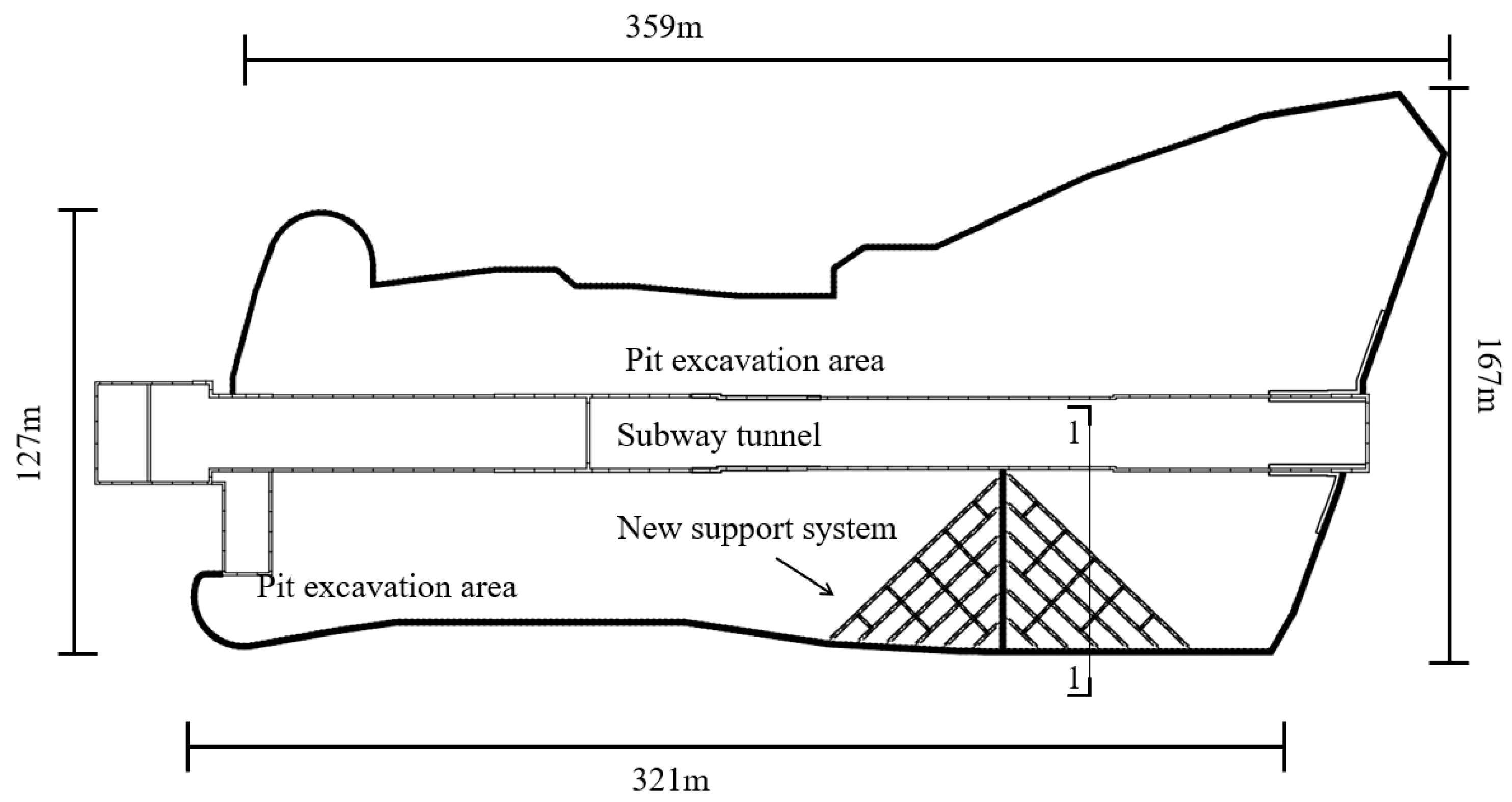
2.1. Engineering Introduction

The project site was located near a coastal tourist attraction in Yantian District, Shenzhen, with a land area of approximately 41,760 m2. The total construction area was approximately 255,863 m2, with a four-story basement. The majority of the project land was located within the scope of the subway station under construction. The excavation depth of the foundation pit was approximately 14.2–19.4 m, the perimeter of the foundation pit was approximately 1192.2 m, and the excavation area of the foundation pit was approximately 30,192.18 m2. The height above the ground of the building was approximately 99.8 m, and there were three basement floors. The basement floor elevation was −8.8 m, and the indoor ±0.000 m ground was equivalent to an elevation of 10.50 m. The underground pipelines inside and around the site were densely distributed, including the water supply, sewage, rainwater, gas, electricity, telecommunications, and other pipelines. The burial depth was relatively low, and most were distributed outside the scope of the project red line. Regarding structural form, the upper structure consisted of a frame shear wall, frame core tube, and frame structure; the lower structure was a frame structure.

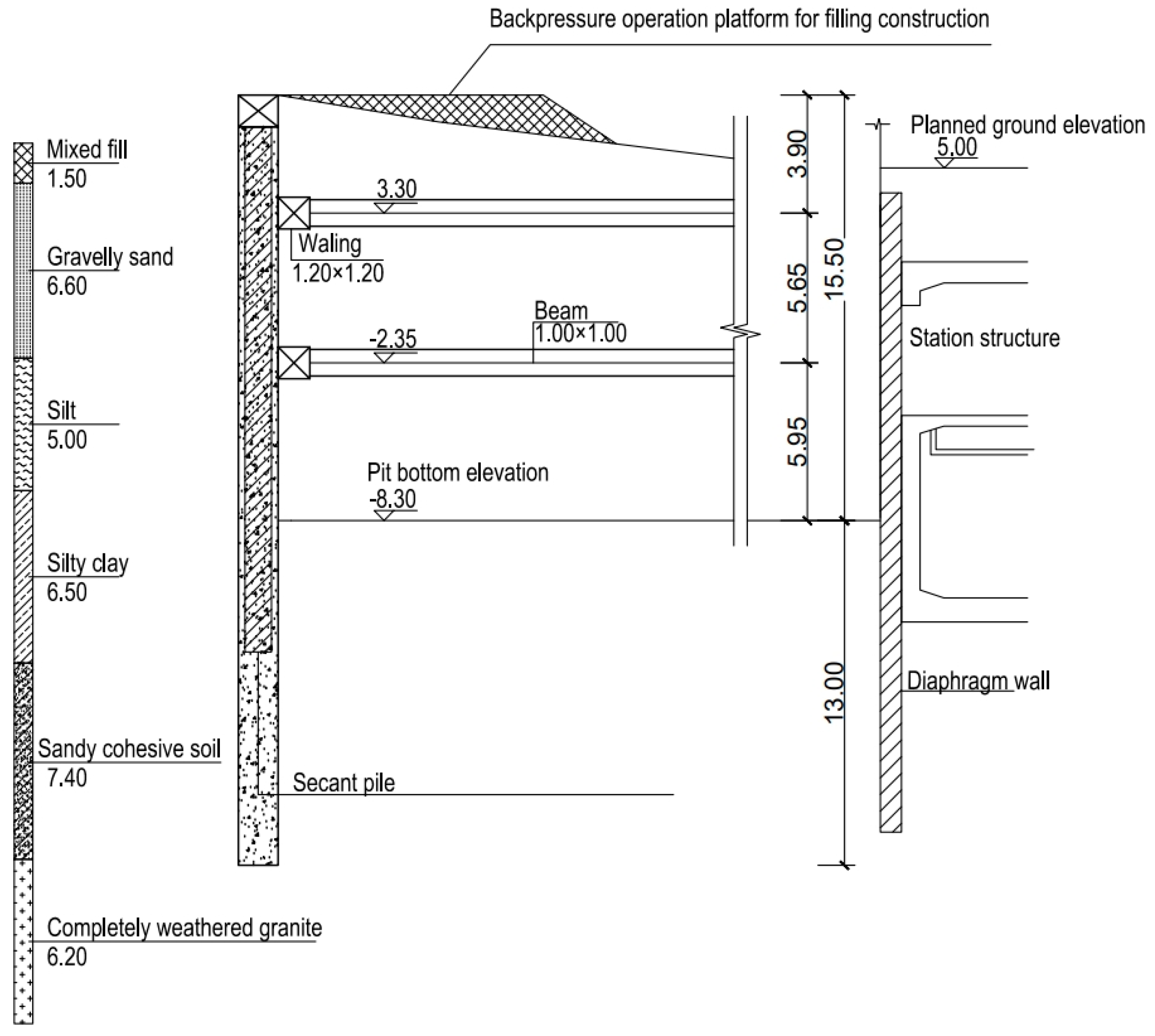
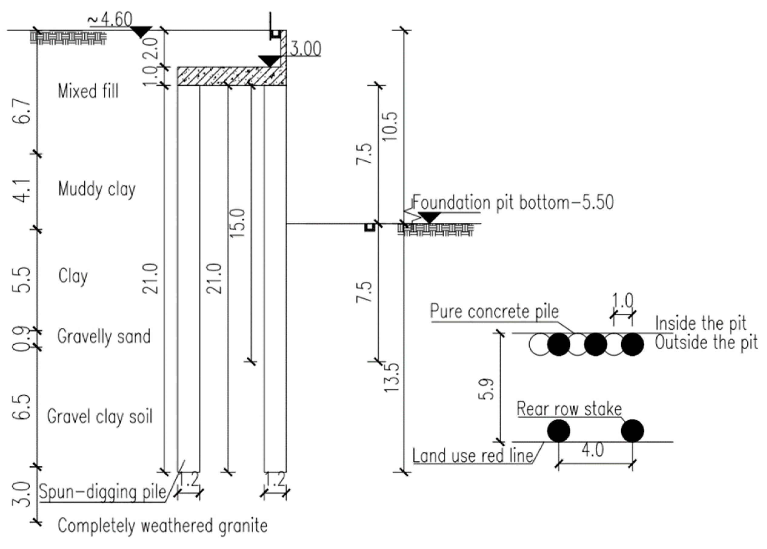
2.2. Engineering Geological Conditions

During the project, the engineering site was flat, and the original geomorphic unit of the proposed site was a mountain-front coastal shallow beach with a relatively flat terrain. After drilling, the various rock and soil layers on the site were divided from top to bottom into an artificial fill (Q4ml), a Quaternary Holocene marine land interaction sedimentary layer (Q4mc), a Quaternary Upper Pleistocene alluvial and proluvial layer (Q3al+pl), and a Quaternary residual layer (Qel). The structural characteristics of each layer can be seen in Table 1:

2.3. Selection and Design of Support Schemes

A challenge concerning foundation pit design was that the foundation pit was deep and large. To reduce the impact of foundation pit excavation on the subway, separate excavation was required. The foundation pit was located on both sides of the subway tunnel and was very sensitive to the surrounding environmental factors. Under sensitive environmental conditions, minimizing the deformation of the ultra-large and ultra-deep foundation pits is required in order to ensure the safety of urban facilities such as surrounding operating subways and important pipelines; this is a challenge that must be overcome in foundation pit design. For deep foundation pit engineering at this depth, commonly used support methods include row pile (wall) and internal support, row pile (wall) and anchor rod support, and double-row pile support. First, because the project involved both sides of the subway tunnel, the construction process (hole forming and grouting) would adversely impact the surrounding area, and the embedded depth of the anchor rod in the row of piles (walls) + anchor rod support would bring uncertainty to the project and affect the stability of the tunnel; thus, anchor rod support should not be used near the tunnel. Secondly, because there were buildings around the foundation pit project, the construction space was narrow, and it was challenging to use double-row piles to construct dense horizontal rows. In addition, due to the long north–south direction of the foundation pit, although the form of a pair of supporting beams can offset the force of the unilateral foundation pit wall, construction is difficult, and the long beams make the stiffness problem difficult to solve. Therefore, pile bracing was used in the foundation pit survey of this project, in addition to the T-shaped layout of slant support. In the new support system, the parameters of the row piles (such as pile spacing, pile diameter, etc.) can be calculated based on commonly used methods. However, for safety reasons, it is necessary to set the row piles of the entire support system as the same, although this design may tend to be conservative. In addition, the beam size of slant support needs to be calculated according to the soil pressure at the pile side, and the transmission of the axial force of the whole structure must be met. The plan of the T-shaped pile support combination support system is shown in Figure 1, and the typical section is shown in Figure 2. The support pile adopted a cast-in-place pile 1.5 m in diameter, with a pile length of approximately 3.0 m and a pile spacing of 1.8 m. The spacing of the slant support was 8 m, and the dimensions were 1 × 1 m, all constructed using C30 concrete. The construction sequence of the pile support section was as follows: site leveling → plain pile construction → support pile construction → rotary jet grouting pile construction (including pit reinforcement) → excavation of the first layer of soil to the bottom elevation of the crown beam → construction of the crown beam → excavation to the bottom elevation of the first support beam and hanging of the mesh spraying surface → construction of the first support beam → excavation to the bottom elevation of the second support beam and hanging of the mesh spraying surface → construction of the second support beam—excavation to the bottom elevation of the foundation pit and hanging of the mesh spraying surface → construction of the basement structure and backfilling of the foundation pit → construction of the upper structure. The construction sequence of the pile anchor support section was as follows: site leveling → plain pile construction → support pile construction → rotary jet grouting pile construction (including pit reinforcement) → crown beam construction → excavating to the elevation of the first anchor cable and hanging the mesh spraying surface → first anchor cable construction → excavation to the elevation of the second anchor cable and hanging of the mesh spraying surface → second anchor cable construction → excavation to the elevation of the third anchor cable and hanging of the mesh spraying surface → third anchor cable construction → excavation to the elevation of the fourth anchor cable and hanging of the mesh spraying surface → fourth anchor cable construction → excavation to the bottom elevation of the foundation pit and hanging of the mesh spraying surface → basement structure construction and backfilling of the foundation pit → upper structure construction.

3. Finite Element Analysis

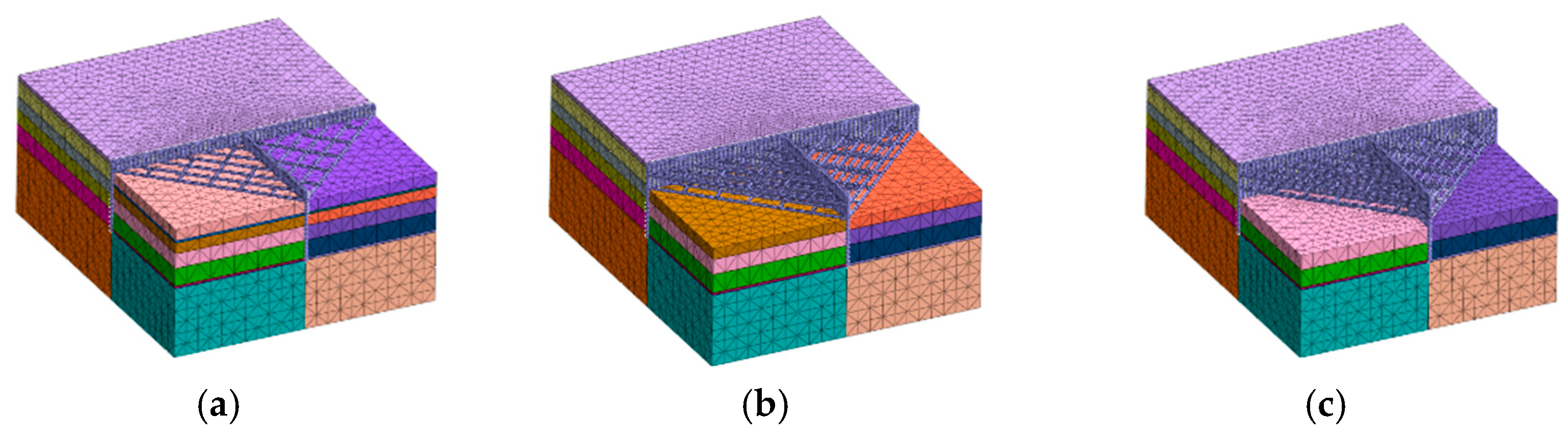
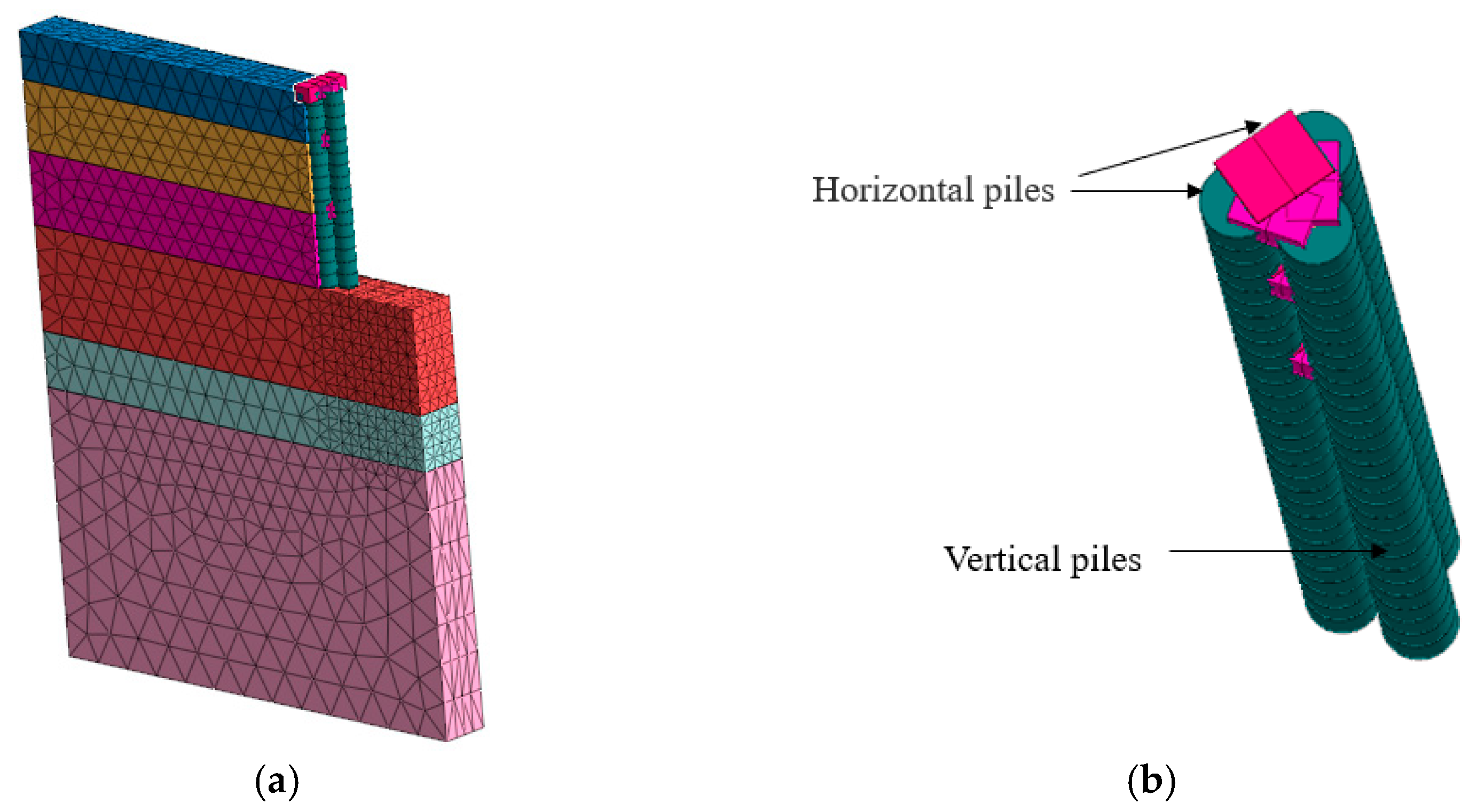
3.1. Numerical Analysis Modelling

This article mainly studies the T-shaped pile support system on the southeast side of the site using finite element software MIDAS GTS NX 2021 RI (19 November 2021). Finite element software was used to simulate and select the area for a 1:1 restoration. The model had a length, width, and height of 128, 107, and 56 m. The model imposed displacement constraints on the surrounding and bottom areas, respectively. The shear yield surface of the modified Mohr Coulomb constitutive law is the same as the yield surface of the Mohr Coulomb constitutive law, and the compressive yield surface is elliptical, as shown in Figure 3. In addition, the shear yield surface and compression yield surface of the modified Mohr–Coulomb constitutive law were independent, and shear hardening and compression hardening models were used. The off-plane shape of the Mohr–Coulomb constitutive law was hexagonal, and special numerical calculation methods needed to be used to calculate the plastic strain direction of the vertices. In order to eliminate unstable factors in the analysis process, the modified Mohr–Coulomb constitutive law used rounded corners to treat the off plane, making the calculation more convergent.
The pit was divided on the left and right sides of the T-shaped pile structure into two areas, one along the horizontal pile direction in the x direction and one along the vertical pile direction in the y direction. Owing to the large number of supporting piles in the model, the monitoring workload was relatively large. Considering the symmetry of the left and right sides of the model, for convenience of observation, the midpoint of the T-shape at the intersection of the horizontal and vertical piles was considered as the starting point, and one pile out of every six was selected as the monitoring object. Our study was conducted only on the left part of the horizontal pile. The 1st, 8th, 15th, 22nd, and 29th piles were studied for both vertical and left lateral piles. Figure 4, Figure 5 and Figure 6 are schematic diagrams of the model and its excavation. Different colors represent different soil qualities, and the colors are randomly generated. The soil layers on the left and right sides of the model with the same horizontal height are consistent. However, due to the segmentation of the support piles, the soil layers on both sides are established separately, resulting in different colors. The model simulated the symmetrical excavation in the left and right regions and the excavation in the left region as follows:
(a)
Simultaneously excavate the left and right areas 4 m to activate the first support;
(b)
Simultaneously excavate the left and right areas 10 m to activate the second support;
(c)
Excavate the left and right areas simultaneously to the bottom of the foundation pit;
(d)
Excavate the left area 4 m and activate the first support;
(e)
Excavate the left area 10 m underground and activate the second support;
(f)
Excavate the left area to the bottom of the foundation pit.

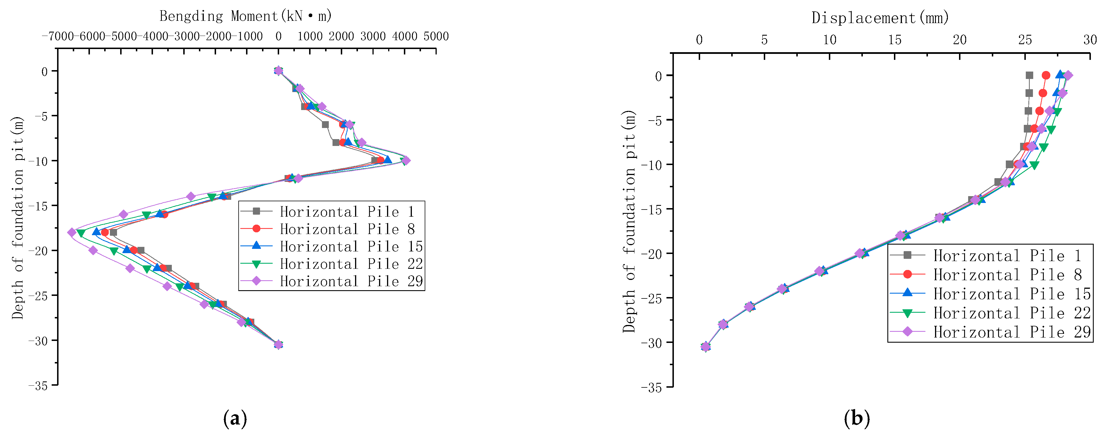
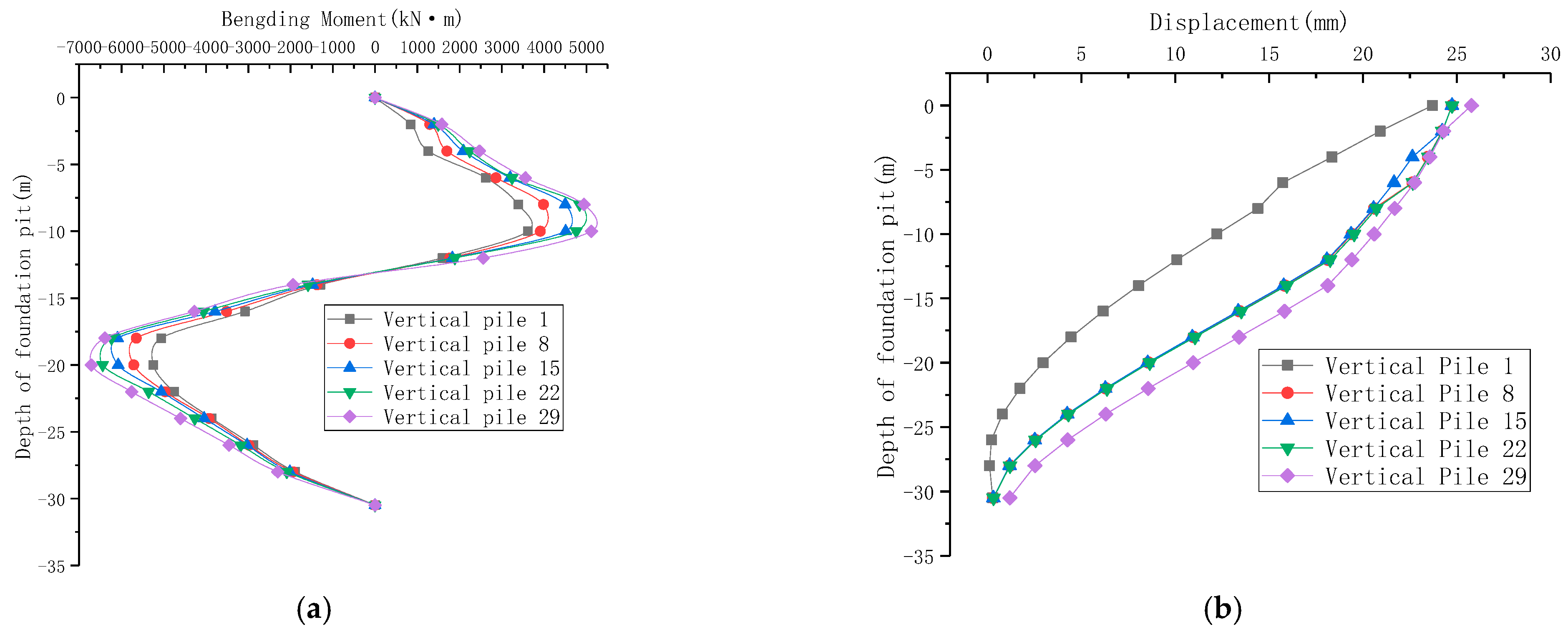
3.2. Symmetrical Excavation Calculation Results

Owing to the small displacement and bending moment when excavating to the first support, the calculation results of the symmetrical excavation primarily helped us to study the displacement and bending moments of the row piles in the x-direction when excavating to the second internal support and the bottom of the foundation pit.
According to the calculation results in Figure 7 and Figure 8, when excavating to the second intermediate support, the bending moment values of both working conditions show an upward “+” and downward “−” trend. The maximum negative bending moment was located in the soil, and the maximum positive bending moment was located at the intersection of the excavated soil surface and the pile. The cantilever end was affected by the active earth pressure, generating a positive bending moment, whereas the embedded section was subjected to passive earth pressure, generating a negative bending moment for pulling. The maximum positive bending moments of the 1st, 8th, 15th, 22nd, and 29th piles from the center of the T-shaped structure toward the edge of the model were 2844, 2905, 3172, 3259, and 3435 kN·m, and the maximum negative bending moments were −2433, −3134, −3183, −3425, and −3854 kN·m. It can be observed that the farther away from the center point, the greater the bending moment, while the situation of the vertical pile was the same as that of the horizontal pile. The displacement of each pile body gradually increased from the bottom to the top of the pile, and the maximum displacement of five piles increased from the center of the T-shaped structure to the edge of the model. The maximum horizontal displacement of the support pile top under symmetrical excavation conditions was 14.8 mm. It can be seen that the deformation effect of the pile in the central area of the T-shaped support structure was relatively low, and the more it developed toward the outside, the greater the deformation. This is predominantly because the vertical piles played a restraining role in the deformations in the middle, and the bending moment of the piles farther away from the T-shaped structure center gradually increased. This was mainly because the deformation of the horizontal piles farther away from the center was transmitted to the vertical piles through the internal support axial force.
Figure 9 and Figure 10 show the calculation results of continuing excavation to the bottom of the foundation pit. The maximum positive and negative bending moments of both vertical and horizontal piles have increased, and the trend of bending moments between piles remains unchanged when excavating to the second support. Owing to the main horizontal force on the piles, when the excavation was deeper, the sliding surface moved downward, and the reverse bending point of the bending moment diagram also moved downward. The maximum horizontal displacement of the top of the horizontal pile was 28.3 mm, which not greater than the design requirement of 30 mm. The horizontal piles transmitted the deformation to the vertical piles through the internal support; the elements of the support system coordinated with each other via the internal support. The maximum horizontal displacement of the vertical piles was 25.8 mm, and the overall structure was stable. From the axial force of the first inner support in Figure 11, it can be seen that the deformation of the horizontal pile is transmitted to the vertical pile through the inner support, and the axial force of the support gradually increases from the inner measurement to the outer measurement.

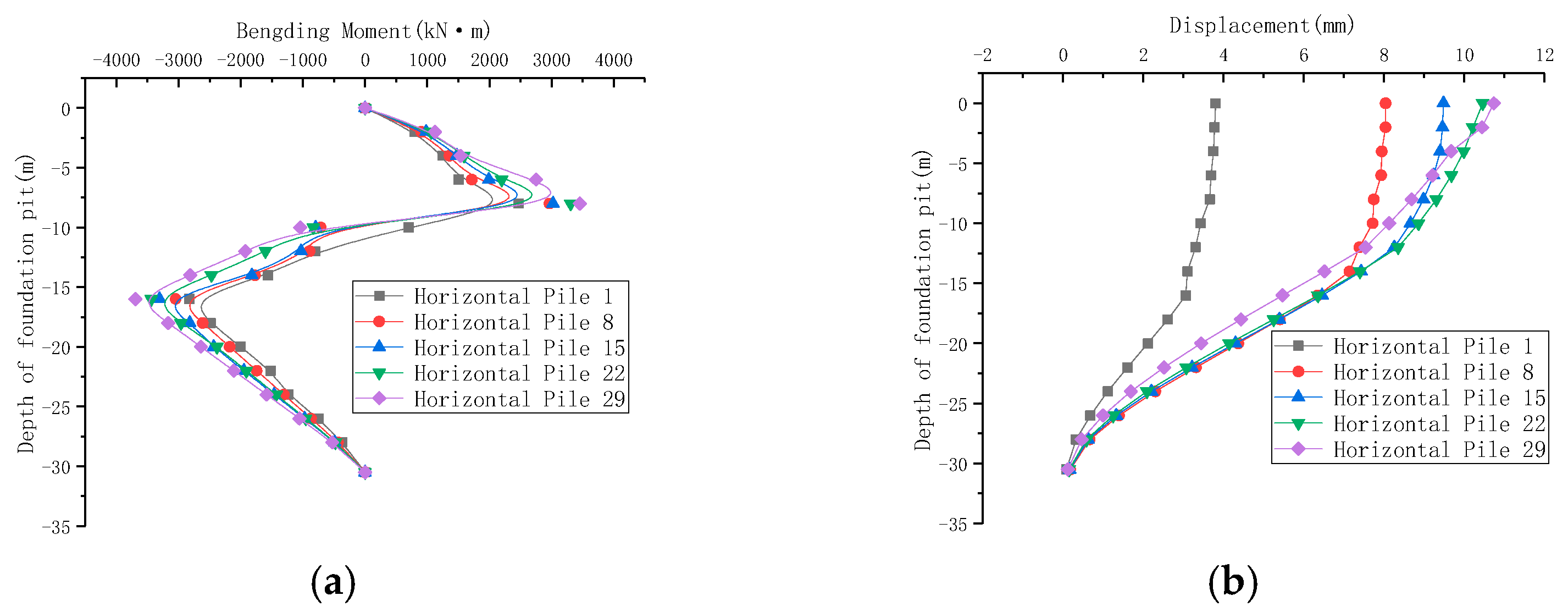
3.3. Asymmetric Excavation Calculation Results

To minimize the impact of the one-time excavation of the foundation pit on the subway, the project excavated on both sides of the foundation pit. Therefore, an asymmetric excavation stage simulation was conducted primarily to study the displacement and bending moment of the horizontal and vertical piles under the unfavorable working conditions of only excavating the left area to the bottom. This study only focused on the support piles related to the excavation area on the left side of the model, and the calculation of the right horizontal piles was not activated. The displacement and bending moment for the vertical piles in the x-direction were studied.
It is required that we consider the displacement of vertical piles under the most unfavorable working conditions for symmetric excavation. According to the calculation results in Figure 12 and Figure 13, when the asymmetric excavation reaches the second support stage, the bending moment forms of horizontal and vertical piles are almost the same.The cantilever end of the support pile was subjected to force, and the form was the same as that of ordinary horizontally loaded piles. The bending moment of the pile body showed a trend of ”+” and “−”, with the maximum displacement value located near the top of the pile, and the maximum displacement of the five vertical piles was 10.7 mm. The minimum horizontal displacement was 3.8 mm, the maximum displacement among the five vertical piles was 10.8 mm, and the minimum horizontal displacement was 5.3 mm. The model was excavated on one side and formed a pit angle at the center of the T-shaped support structure. It can be seen that the greater the distance of the support pile from the pit angle, the greater the bending moment, and the displacement also increases significantly. However, the increasing trend of the horizontal displacement of the pile body gradually stabilized from the 15th pile onward, which is attributable to the pit angle effect limiting the deformation of the foundation pit, but the scope of its influence was limited.
Figure 14 and Figure 15 show the calculation results of asymmetric excavation. Due to the increase in active soil pressure, the maximum bending moment of the pile body reaches −6773 kN·m. The maximum bending moment value decreased with the excavation depth. The changing trends of the maximum bending moment and maximum displacement are attributable to the pit angle effect. The maximum horizontal displacements of the top of the horizontal and vertical piles were 23.2 and 21.9 mm, respectively. The maximum displacement was on the 29th pile in both directions, and the horizontal displacement of the top of the pile was not greater than the warning value of 30 mm. At this point, if the right-side area was excavated, it led to a decrease in the active soil pressure in the X direction of the vertical piles, so the overall structure was stable and able to meet the requirements of pit excavation. From the axial force of the first inner support in Figure 16, it can be seen that the axial force of the inner support gradually increases from the outer side of the pit angle to the inner side.

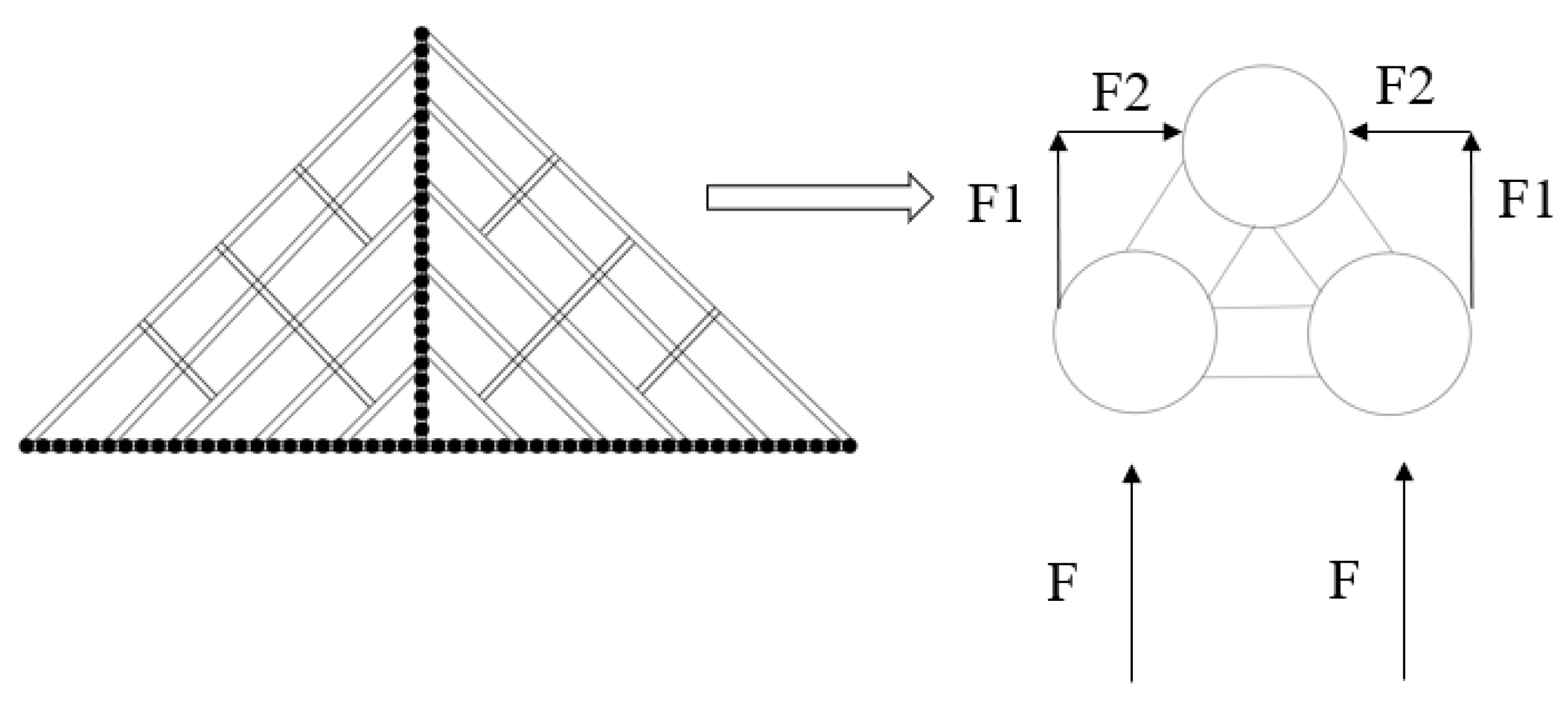
4. Simplification of Support Structure Model

4.1. Establishment of Simplified Models

The T-shaped retaining structure had a unique shape similar to that of an isosceles triangle in plane space. The horizontal piles of the retaining structure were directly in contact with the foundation pit wall, and the horizontal pile structures were connected. Under the condition of symmetrical excavation, the active earth pressure was transmitted to the vertical retaining structure in the middle through the diagonal support, maintaining the overall stability of the foundation pit. Although the structure was complex, the entire support structure could be simply decomposed into multiple isosceles triangles, as shown in Figure 17. The model in Figure 18 shows that different colors represent different soil qualities, and the colors are randomly generated. In order to study the T-shaped support structure in more detail, simplified models with length, width, and height of 31 m, 4 m, and 50 m were established using finite element software, as shown in Figure 18. The piles were connected through waist beams, crown beams, and internal supports, with a crown beam specification of 1.5 × 1.2 m. The model applied displacement constraints to the surrounding and bottom regions, and the modified Mohr–Coulomb constitutive model was used to calculate the soil mass. The simplified model only studied the deformation of the structure when the foundation pit was excavated to the bottom.

4.2. Calculation Results

The calculation results (Figure 19) show that the difference in bending moments between the two horizontal piles was minuscule, indicating that the waist beam and crown beam connected the horizontal piles as an overall coordinated structure, but the maximum bending moment values of the two horizontal piles were smaller than those of the vertical piles. It can be assumed that the connection between each horizontal and vertical pile was an equivalent plane rigid frame structure. If the design was based on normal double-row piles, the front and rear piles should have had two support piles, but here, they were in the form of slant support. The active earth pressure borne by the two horizontal piles was transmitted to the vertical pile through the internal support and the crown beam. The front row and vertical piles were pushed by the two piles, and the force was greater. Therefore, the bending moment should have been greater than that of a single horizontal pile, as the support structure produced a movement trend toward the interior of the foundation pit after excavation. The length of the vertical pile above the sliding surface was greater than that of the horizontal pile, so the depth provided by the vertical pile relative to the rear pile to prevent soil displacement was greater. Therefore, the depth at which the bending moment reverse bending point of the pile body appears should be higher. The horizontal and vertical rows of piles were connected by internal supports and crown beams, so the displacement difference was not significant.

5. Comparison of Support Structure Degradation

T-shaped pile support structures are all cantilever piles, in which vertical piles are similar to columns, and horizontal piles and vertical piles are connected through internal supports. After being simplified to an isosceles triangle, the load distributed in a triangle by the active earth pressure acting on the horizontal piles could be simplified to the axial force F on the internal support, and the diagonal support transmitted F to the vertical piles. The active earth pressure was decomposed into the horizontal component F2 and the vertical component F1 through the F of the diagonal support. In the case of symmetrical excavation of the left and right soil, the left component F2 was offset by the right component F2, and the vertical pile was only subjected to the vertical component F1 in one direction so that the isosceles triangle structure could be degraded into a cantilever double-row pile support structure. Figure 20 is a simple schematic diagram of the entire degradation process.From this, it can be seen that the stress form of the T-shaped structure can degenerate into a double-row pile support structure. From reference [30], it can be seen that the cantilever double-row pile had similar stress, with the pile bending moment showing a trend of “+” and “−”, and the pile displacement value gradually increasing from the bottom to the top of the pile. As shown in Figure 18 of a Shenzhen Shenwan project similar to the design of the double-row pile in reference [30], the excavation depth of the support structure was 10.5 m, the pile length was 21 m, and the embedding depth is 13.5 m. The upper part of the horizontal plate of the weighing platform was the upper retaining plate, with a height of 3 m. The lower part was the support cantilever section, with a height of 7.5 m. The width of the horizontal plate of the weighing platform was about 4 m. The front row of the support pile was an interlocking pile with a diameter of 1200 mm, arranged in a “one meat and one vegetable” manner (the meat pile is a reinforced concrete pile, and the vegetable pile is a plain concrete pile) with a spacing of 2 m. The rear row piles were rotary bored piles with diameters of 1200 mm and spacing of 4 m. Figure 21 is the engineering cross-section of the Qianhai project.By comparing the trend of pile displacement values of a certain project in Qianhai (Figure 22) with the pile displacement values in this article, it can be seen that the T-shaped pile support structure is able to achieve the effect of double-row piles from a three-dimensional perspective, but the number of front row support piles is saved through slant support, thus saving space. For the super-deep foundation pit which was excavated, the stability of each excavation area was maintained.

6. Conclusions

This study used numerical simulation methods to study the deformation of the support structure and foundation pit. Two working conditions of symmetric and asymmetric excavation were employed using a T-shaped pile support structure. A simplified model was established and compared with the degradation of the cantilever double-row pile support structure. The similarities and differences between the two support systems were compared, and the research results indicated that:
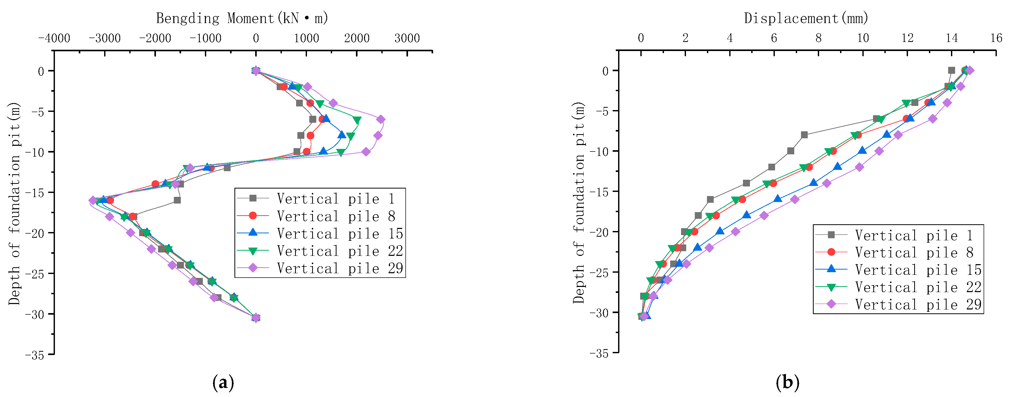
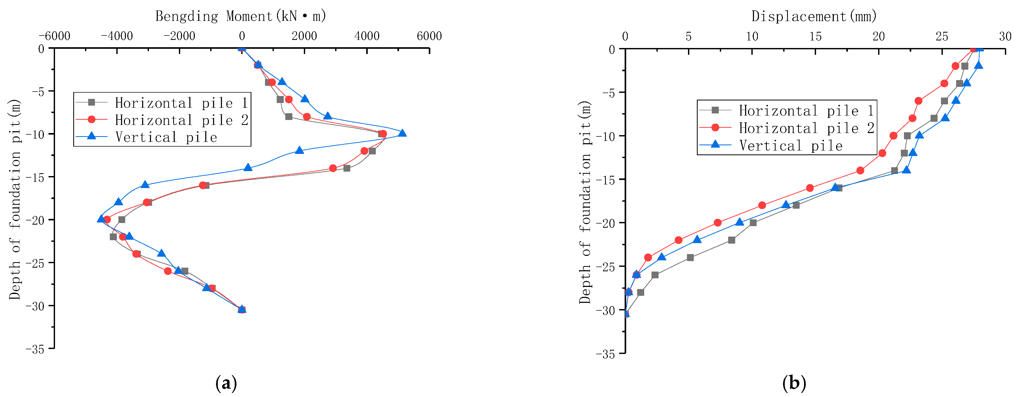
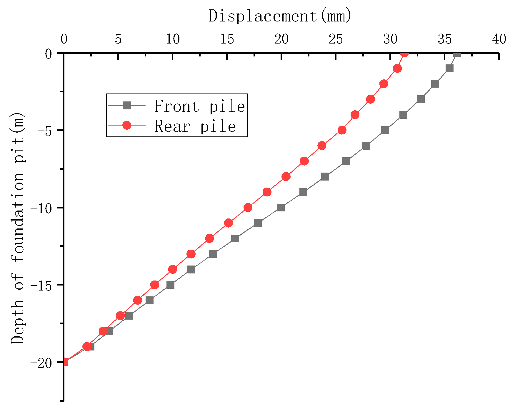
  • When a T-shaped pile support structure was symmetrically excavated, the entire support system was formed into a whole through internal support. The overall stress form was the horizontal piles near the soil side being subjected to active soil pressure, and the vertical piles being pushed by internal support. Traveling farther away from the center point of the T-shaped structure, the maximum bending moment and maximum displacement values of the horizontal and vertical piles demonstrated an upward trend. The vertical piles imposed a constraint on the deformation of the central area. The displacement of the pile top on the side of the vertical pile near the tunnel was the largest, but not greater than the warning value of 30 mm. The overall structure met the design requirements.
  • During the asymmetric excavation of the T-shaped pile support structure, a pit angle was formed at the center point of the T-shaped structure. The farther away from the pit angle, the greater the maximum bending moment and maximum displacement values of the horizontal and vertical piles. However, the rate of increase decelerated at the left and right positions of the 15th pile. The maximum displacement value of the vertical pile in the x-direction was 21.9 m. The force of the vertical and horizontal piles in the y-axis direction was offset by the internal support. At this time, if the right side of the foundation pit was excavated, the active soil pressure of the vertical piles decreased in the x direction, and the vertical piles were safe in the x direction.
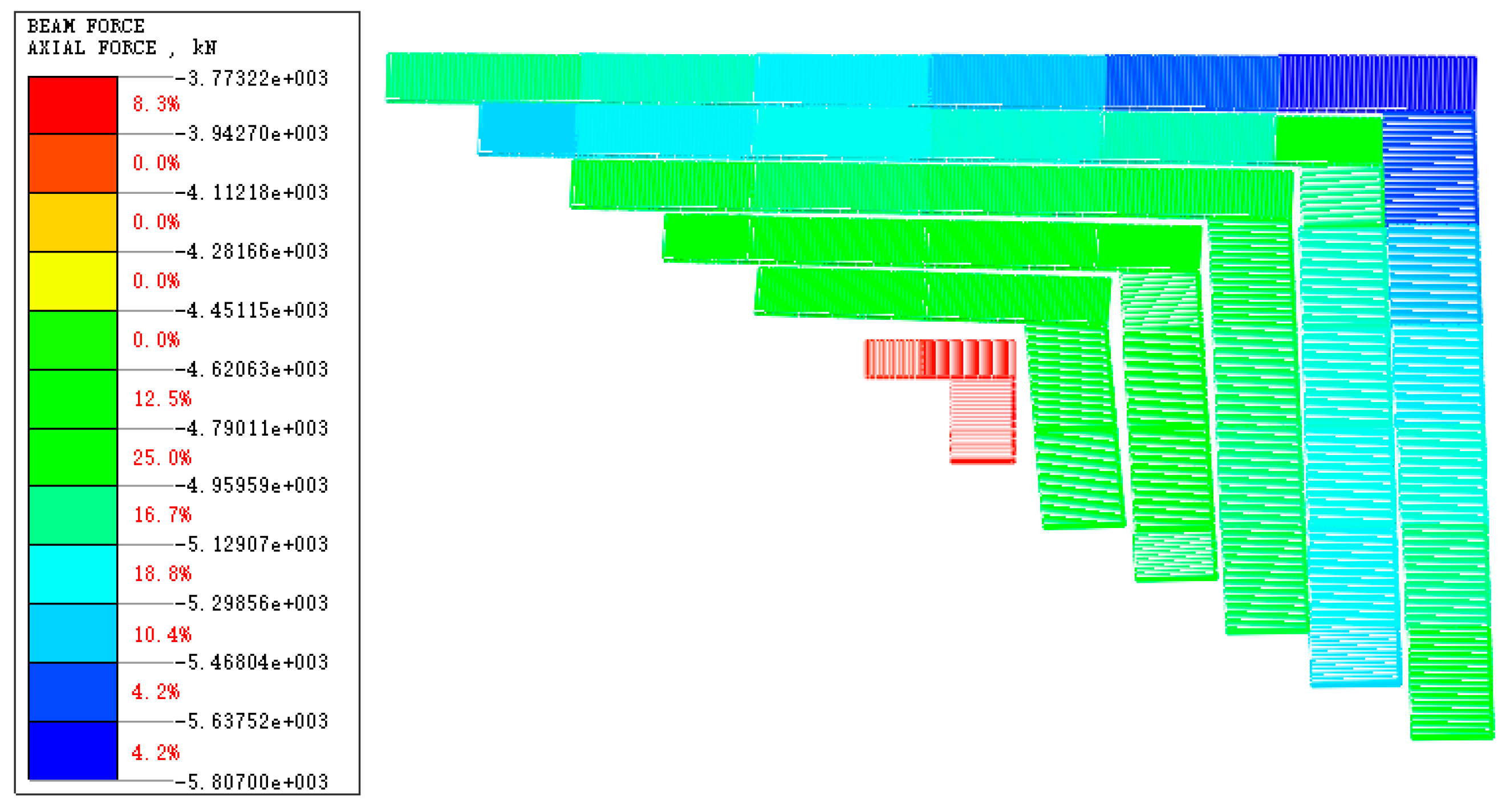
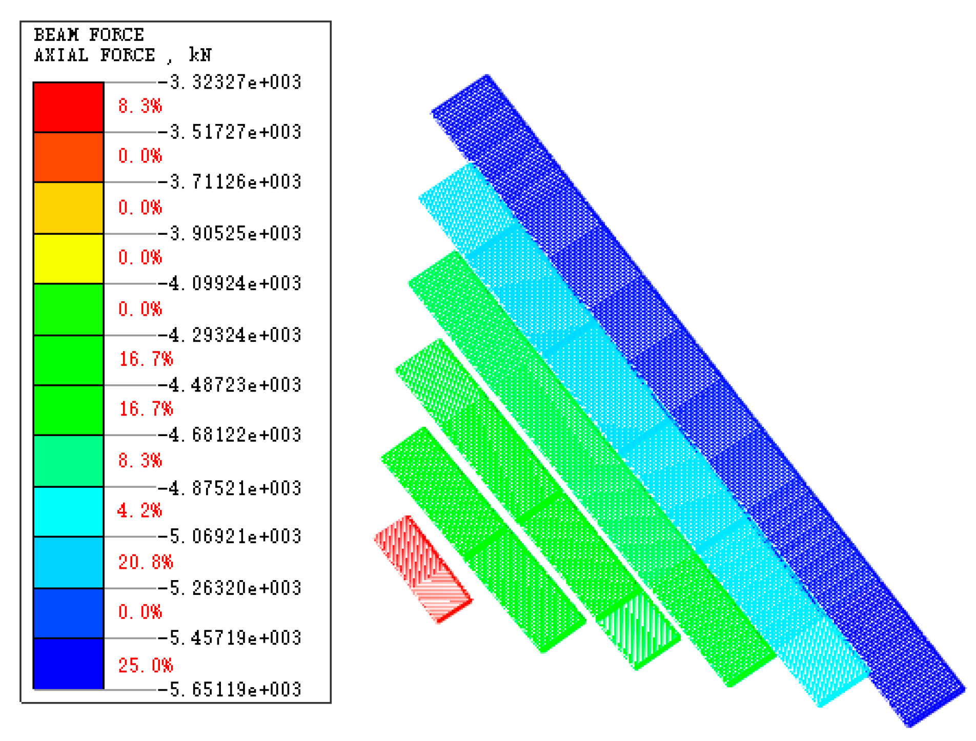
  • From the displacement and bending moment diagrams of each excavation stage, it can be seen that the greater the distance from the center point of the T-shaped structure, the greater the increase in the bending moment and pile displacement. Therefore, in practical engineering, it is required to monitor the deformation of support piles that are farther from the center. From the axial force trend of the inner support, the outer inner support had the highest axial force. Attention should be paid to the design of the inner support in order to prevent the outer inner support from breaking during the excavation of the foundation pit.
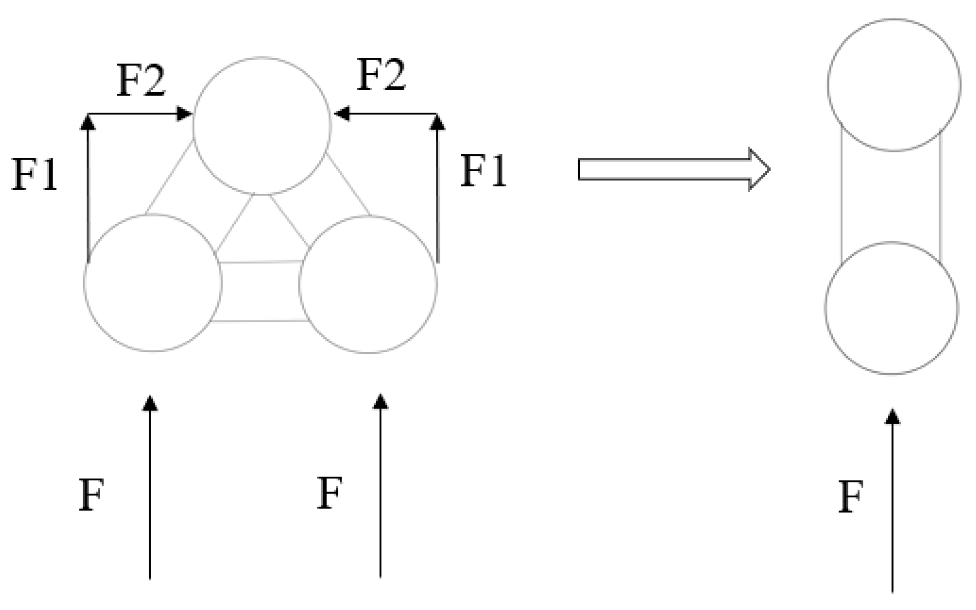
  • Through a comparison of degradation, it can be seen that the T-shaped support structure can be simplified into a triangular support structure. The partial thrust between the two horizontal rows of piles in the triangular support structure canceled out, and then degenerated into an ordinary cantilever double-row pile structure. The stress form was similar to that of ordinary double-row piles, but the arrangement of the piles could be reduced in space. Compared with the form of the supporting beams in the entire foundation pit, this can meet the additional requirements of pit excavation.
Due to the ongoing construction of the foundation pit project, on-site monitoring data cannot be obtained in this article at present. We can only compare the degradation of the structure first. The next step should be to compare our results with on-site data. It will be best to design some on-site experiments in order to verify and propose a complete theoretical calculation of the structure.

Author Contributions

J.L.: Conceptualization, methodology, supervision, project administration. H.J.: Methodology, software, data processing, writing—original draft. All authors have read and agreed to the published version of the manuscript.

Funding

The publishing of this paper is financially supported by China Academy of Railway Sciences Corporation Limited (No.2023YJ172 and No.2021YJ166).

Institutional Review Board Statement

Not applicable.

Informed Consent Statement

Not applicable.

Data Availability Statement

The data presented in this study are available on request from the corresponding authors.

Conflicts of Interest

The authors declare no conflict of interest.

References

  1. Zhou, Y.; Li, S.; Zhou, C.; Luo, H. Intelligent approach based on random forest for safety risk prediction of deep foundation pit in subway stations. J. Comput. Civ. Eng. 2019, 33, 05018004. [Google Scholar] [CrossRef]
  2. Shen, Y.; Wang, P.; Li, M.; Mei, Q.-W. Application of subway foundation pit engineering risk assessment: A case study of Qingdao rock area, China. KSCE J. Civ. Eng. 2019, 23, 4621–4630. [Google Scholar] [CrossRef]
  3. Zhou, Y.; Su, W.; Ding, L.; Luo, H.; Love, P.E.D. Predicting safety risks in deep foundation pits in subway infrastructure projects: Support vector machine approach. J. Comput. Civ. Eng. 2017, 31, 04017052. [Google Scholar] [CrossRef]
  4. Chen, G.; Zhang, X.; Zhang, S.; Huang, F.; Xiao, H.; Ma, H.; Luo, L.; Bao, H. Response Monitoring and Analysis in Deep Foundation Pit Excavation: A Case Study in Soft Soil at Subway Tunnel Intersections. Buildings 2023, 13, 1286. [Google Scholar] [CrossRef]
  5. Yang, J.; Kong, D. Deformation of deep and large foundation pit in soft soil of Fuzhou Subway. Arab. J. Geosci. 2020, 13, 36. [Google Scholar] [CrossRef]
  6. Qiu, H.; Zhou, Y.; Ayasrah, M. Impact Study of Deep Foundations Construction of Inclined and Straight Combined Support Piles on Adjacent Pile Foundations. Appl. Sci. 2023, 13, 1810. [Google Scholar] [CrossRef]
  7. Tan, Y.; Wei, B. Observed behaviors of a long and deep excavation construction by cut-and-cover technique in Shanghai soft clay. J. Geotech. Geoenviron. Eng. 2012, 138, 69–88. [Google Scholar] [CrossRef]
  8. Tan, Y.; Wei, B.; Zhou, X.; Diao, Y. Lessons learned from construction of Shanghai metro stations: Importance of quick excavation, promptly propping, timely casting and segmented construction. J. Perform. Constr. Facil. 2015, 29, 04014096. [Google Scholar] [CrossRef]
  9. Zhao, X.; Wang, H.; Li, Z.; Dai, G.; Yin, Z.; Cao, S.; Zhou, J. Numerical study on the deformation of tunnels by excavation of foundation pit adjacent to the subway. Appl. Sci. 2022, 12, 4752. [Google Scholar] [CrossRef]
  10. Gui, Y.; Zhao, Z.; Qin, X.; Wang, J. Study on Deformation Law of Deep Foundation Pit with the Top-Down Method and Its Influence on Adjacent Subway Tunnel. Adv. Civ. Eng. 2020, 2020, 8852336. [Google Scholar] [CrossRef]
  11. Xu, P.; Han, Y.; Duan, H.; Fang, S. Environmental Effects Induced by Deep Subway Foundation Pit Excavation in Yellow River Alluvial Landforms. Geotech. Geol. Eng. 2015, 33, 1587–1594. [Google Scholar] [CrossRef]
  12. Wu, D.; Liu, H.; Kong, G.; Ng, C.W.W. Interactions of an Energy Pile with Several Traditional Piles in a Row. J. Geotech. Geoenviron. Eng. 2020, 146, 06020002. [Google Scholar] [CrossRef]
  13. Jianping, F.; Songchao, L.; Kai, L. Multi-scale study of load-bearing mechanism of uplift piles based on model tests and numerical simulations. Sci. Rep. 2023, 13, 6410. [Google Scholar]
  14. Aamer, F.; Azzam, W.; Farouk, A.; Nasr, A.; Nazir, A. Utilization of blade anchor for improving the uplift capacity of pile in sand: Model Study. Ocean Eng. 2023, 278, 114435. [Google Scholar] [CrossRef]
  15. Ma, H.; Ma, Y.; Zhu, L.; Zhang, H. Experimental Study on the Difference Mechanism of Shaft Resistance between Uplift Piles and Compressive Piles. Appl. Sci. 2023, 13, 3158. [Google Scholar] [CrossRef]
  16. Lin, Z.; Ma, H. Study on the rupture surface morphology and ultimate bearing capacity of a self-anchored test pile. Sci. Rep. 2022, 12, 16382. [Google Scholar]
  17. Sun, Y.; Li, Z. Study on Design and Deformation Law of Pile-Anchor Support System in Deep Foundation Pit. Sustainability 2022, 14, 12190. [Google Scholar] [CrossRef]
  18. Cheng, K.; Xu, R.Q.; Ying, H.W.; Gan, X.L.; Zhang, L.S. Performance of Diaphragm Walls in Soft Clay of a Deep Basement Excavation. Soil Mech. Found. Eng. 2022, 59, 159–166. [Google Scholar] [CrossRef]
  19. Zhu, Y.; Sun, F.; Liu, M.; Liu, Q.; Li, X.; Ge, G. Numerical Simulation Study on Construction Effect of Top-Down Construction Method of Suspended Diaphragm Wall for Deep and Large Foundation Pit in Complex Stratum. Adv. Civ. Eng. 2022, 2022, 8201726. [Google Scholar] [CrossRef]
  20. Feng, C.; Cheng, Z.; Zhu, L. Performance of Prestressed Anchor Cables Supporting Deep Foundation Pit of a Subway Station during Spring Thaw. Geofluids 2022, 2022, 3567816. [Google Scholar] [CrossRef]
  21. Wang, W.; Han, Z.; Deng, J.; Zhang, X.; Zhang, Y. Study on soil reinforcement param in deep foundation pit of marshland metro station. Heliyon 2019, 5, e02836. [Google Scholar] [CrossRef]
  22. Liu, X.; Liu, Y.; Yang, Z.; He, C. Numerical analysis on the mechanical performance of supporting structures and ground settlement characteristics in construction process of subway station built by Pile-Beam-Arch method. KSCE J. Civ. Eng. 2017, 21, 1690–1705. [Google Scholar] [CrossRef]
  23. Deng, Y.; Zhang, K.; Yao, Z.; Zhao, H.; Li, L. Parametric analysis and multi-objective optimization of the coupling beam pile structure foundation. Ocean Eng. 2023, 280, 114724. [Google Scholar] [CrossRef]
  24. Wang, T.; Ma, H.; Liu, K.; Luo, Q.; Xiao, S. Load transfer and performance evaluation of piled beam-supported embankments. Acta Geotech. 2022, 17, 4145–4171. [Google Scholar] [CrossRef]
  25. Dong, Y.; Luan, Y.; Wang, F.; Yang, H.; Jia, Z.; Luan, H. Monitoring and Prediction of Horizontal Displacement of Underground Enclosure Piles in Subway Foundation Pits. ACS Omega 2023, 26, 23389–23400. [Google Scholar] [CrossRef]
  26. Yin, Q.; Fu, H.L. Analysis of Foundation Pit Excavation Deformation and Parameter Influence of Pile-Anchor-Ribbed-Beam Support System. Appl. Sci. 2023, 13, 2379. [Google Scholar] [CrossRef]
  27. Zhang, Y.; Jin, Z.; Hou, Y.; Han, B.; Ntakiyimana, C. Fluid-Solid Coupling Effect on Numerical Simulation of Deep Foundation Pit Deformation in Soft Soil Area. Appl. Sci. 2022, 12, 11242. [Google Scholar] [CrossRef]
  28. Sun, F.; Liu, M.; Zhu, Y.; Li, X.; Ge, G. Research on Numerical Simulation of Top-Down Construction Effect of Diaphragm Wall of Deep and Large Foundation Pit under Different Working Conditions in Complex Stratum. Adv. Civ. Eng. 2022, 2022, 2576122. [Google Scholar] [CrossRef]
  29. Lin, P.; Liu, P.; Ankit, G.; Singh, Y.J. Deformation Monitoring Analysis and Numerical Simulation in a Deep Foundation Pit. Soil Mech. Found. Eng. 2021, 58, 56–62. [Google Scholar] [CrossRef]
  30. Gu, W.-T. Study on Double-Row Piles Retaining Structure with Relieving Platform; China Academy of Railway Sciences: Beijing, China, 2018. [Google Scholar]
Figure 1. Foundation Pit design plan.
Applsci 13 11240 g001
Figure 2. 1−1 Section.
Applsci 13 11240 g002
Figure 3. Correction of the yield surface of Mohr–Coulomb in the p-q plane.
Applsci 13 11240 g003
Figure 4. Model construction diagram. (a) Model overview; (b) T-shaped pile support.
Applsci 13 11240 g004
Figure 5. Schematic of the working condition. (a) Symmetrical excavation to the first supporting beam; (b) Symmetrical excavation to the second supporting beam; (c) Symmetrical excavation to the bottom of the foundation pit.
Applsci 13 11240 g005
Figure 6. Schematic of the second working condition. (a) Asymmetric excavation to the first supporting beam; (b) Asymmetric excavation to the second supporting beam; (c) Asymmetric excavation to the bottom of the foundation pit.
Applsci 13 11240 g006
Figure 7. Bending moment and displacement diagrams of the left horizontal pile during symmetrical excavation to the second support. (a) Bending moment diagram; (b) displacement.
Applsci 13 11240 g007
Figure 8. Bending moment and displacement diagrams of the vertical piles under symmetrical excavation to the second support condition. (a) Bending moment diagram; (b) displacement.
Applsci 13 11240 g008
Figure 9. Bending moment and displacement diagrams of horizontal piles during symmetrical excavation to the bottom of the foundation pit. (a) Bending moment diagram; (b) displacement.
Applsci 13 11240 g009
Figure 10. Bending moment and displacement diagrams of vertical piles during symmetrical excavation to the bottom of the foundation pit. (a) Bending moment diagram; (b) displacement.
Applsci 13 11240 g010
Figure 11. Diagram of the first internal support axis.
Applsci 13 11240 g011
Figure 12. Bending moment diagram and displacement diagram of the left lateral pile during asymmetric excavation to the second support. (a) Bending moment diagram; (b) displacement.
Applsci 13 11240 g012
Figure 13. Bending moment diagram and displacement diagram of vertical row piles under asymmetric excavation to the second support working condition. (a) Bending moment diagram; (b) displacement.
Applsci 13 11240 g013
Figure 14. Bending moment diagram and displacement diagram of horizontal piles during asymmetric excavation to the bottom of the foundation pit. (a) Bending moment diagram; (b) displacement.
Applsci 13 11240 g014
Figure 15. Bending moment and displacement diagrams of vertical piles during asymmetric excavation to the bottom of the foundation pit. (a) Bending moment diagram; (b) displacement.
Applsci 13 11240 g015
Figure 16. Diagram of the first inner support axis in the left area.
Applsci 13 11240 g016
Figure 17. Schematic of transformation of the T-shaped pile support structure model.
Applsci 13 11240 g017
Figure 18. Simplified model diagram. (a) Model overview; (b) simplified T-shaped pile support structure.
Applsci 13 11240 g018
Figure 19. Simplified model moment, bending moment, and displacement diagrams. (a) Bending moment diagram; (b) displacement.
Applsci 13 11240 g019
Figure 20. Schematic of support structure degradation.
Applsci 13 11240 g020
Figure 21. Plan and section of double row piles.
Applsci 13 11240 g021
Figure 22. Displacement diagram of double-row piles.
Applsci 13 11240 g022
Table 1. Structural properties adopted in the numerical analysis.
Stratum NameDeformation Modulus
(kN/m2)
Tangent Stiffness
(kN/m2)
Secant
Stiffness (kN/m2)
Unloading
Elastic Modulus
(kN/m2)
Internal
Friction Angle (°)
Poisson RatioUnit Weight (g/cm3)
Artificial fill450013,50013,50040,500150.361.95
Gravelly Sand28,00084,00084,000252,000340.311.75
Silt20006000600018,00040.331.65
Silty Clay10,00030,00030,00090,000160.381.94
Sandy Cohesive Soil16,00048,00048,000144,000220.331.82
Completely Weathered Granite60,000180,000180,000540,000330.261.84
Disclaimer/Publisher’s Note: The statements, opinions and data contained in all publications are solely those of the individual author(s) and contributor(s) and not of MDPI and/or the editor(s). MDPI and/or the editor(s) disclaim responsibility for any injury to people or property resulting from any ideas, methods, instructions or products referred to in the content.

