Article

Study on Mechanism of Static Blasting-Induced Hard Rock Fracture Expansion

1
School of Mining Engineering, China University of Mining and Technology, Xuzhou 221116, China
2
Coal Mining and Designing Branch, China Coal Research Institute, Beijing 100013, China
*
Author to whom correspondence should be addressed.
Appl. Sci. 2023, 13(20), 11310; https://doi.org/10.3390/app132011310
Submission received: 19 September 2023 / Revised: 10 October 2023 / Accepted: 13 October 2023 / Published: 14 October 2023

Abstract

:
How to deal with hard rock cheaply and safely is a pressing issue in today’s coal mining. Weakening fractures of hard rock have always been a significant concern in China’s coal mine engineering. In this study, mechanical derivation, laboratory experiments, and numerical simulation research methodologies are used to evaluate the fracturing process of the static crushing agent (SCA). From a mechanical standpoint, the mechanism of fracturing hard rock by a crushing agent is investigated. It is assumed that single-hole fracturing is separated into three stages: the microfracture stage, the fissure development stage, and the breaking stage. The swelling and fracturing properties of SCA were quantitatively analyzed. It was found that the swelling pressure of SCA increased with the increase in pore diameter, and the range of the swelling pressure was 43.5 MPa to 75.1 MPa. SCA exhibited a delayed fracture initiation, but the rate of breakage was relatively high. The cracking effect of a single-hole specimen under no peripheral pressure was simulated using PFC2D, and the results were consistent with experimental observations. The internal dynamic effect, crack extension, distribution characteristics, and the development law of double-hole expansion pressure were analyzed for double-hole specimens with different hole diameters, hole spacings, and circumferential pressures. It was observed that the cracking effect was positively correlated with the pore diameter, while the pore spacing and surrounding pressure were negatively correlated. The size of the expansion pressure was negatively correlated with the pore diameter, while the pore spacing and surrounding pressure were positively correlated.

1. Introduction

China has abundant coal resources, but as mining efficiency improves, shallow coal mining is giving way to deep mining [1,2,3]. Unfortunately, hard rock is abundant in deep mining, which creates several challenges for rock construction. These include ineffective hard rock canyon excavation, hard top board failure, over-the-top hard rock rupture, and other problems [4,5,6]. These issues significantly limit the efficiency of coal mining operations. Consequently, it is crucial to find novel hard rock cracking techniques that are affordable, safe, green, and efficient. One such technique is static fracture (SCA), which involves injecting water and SCA into the target body in a specific proportion. Through a chemical reaction, the generated expansion pressure causes the target bodies to crack without fire, flying stones, or other hazards [7,8]. This technology has been mainly used in subterranean process building in recent years due to the safety expenses involved in hard roof plate pre-break, rocky street expansion, working surface rupture, and coal layer penetration [9,10,11].
Researchers from around the world have conducted extensive studies on static cracking technology and have produced valuable results. In theory, the process of cracking and destroying single-porous rocks can be divided into three stages: the microcracking stage, the cracking development stage, and the breaking stage. This is achieved by creating a mechanical model that examines the impact of expansion pressure [12]. A mechanical model based on rock-breaking units was developed by Zhou Yuan Tao et al. [13]. Zhou Yuan Tao and his co-researchers were able to derive the stress intensity factor expression at the drilling crack’s tip, as well as the three-stage crack length expression of the perforation crack’s expansion. These findings can serve as a theoretical foundation for the design of statistical cracks. Wang Yueja [14] developed a new sputtering hypothesis called “intensive captive bubble pressure chamber” through experimental data. Liu Xiaoping [15] distinguished between the elastic and non-elastic stages of the expansion phase in his mechanical analysis of splinter expansion. Gaoyang [16] established the mechanical model, crack, and expansion laws of rocks, including pre-break, but the theoretical analysis of the static crack does not consider pre-break. Yujiang and colleagues [17] established that the PVC pipe has a specific directed main cracking effect on expansion and cracking by sewing it into concrete test center holes of varying intensities. Based on the expansion pressure data, Nanjing Wei and other [18] individuals ran the SCA coal corpus model destruction experiment. The experiment’s outcomes supported the viability of using static cracking in well-known coal bodies. Yang Dong [19] evaluated the expansion pressure using indoor experiments in which the expansion’s development rule was first made more complex and then made simpler. He also examined how temperature affected the expansion’s development. Wang Qingqiang [20] quantifies the relationship between the development features of micro-seismic signals and the electromagnetic signal in the process of rock expansion and cracking. He does this by using microscopic and electromagnetic analysis of the static and dynamic cracking of rocks. To further explore the properties of the static splinter-causing test object under stress through sound-release technology, Hao B. Y. and colleagues [21] employed genuine three-axis double-stress loading experiments. Laefer D. F. et al.’s [22] investigation of static fissures in various probe comparative intensities under the influence of ambient temperature revealed that raising ambient temperatures, lowering design comparative temperatures, and increasing melting temperatures would all hasten the expansion of the fissures. Aspects of numerical simulation: Tang Xianlie and others [23] used simulations to examine the growth and elimination of single-porous square concrete cracks caused by static crushers. Cheng [24] examined the effects of hole diameter, hole spacing, and hole depth on the static fracture of rock using FLAC3D software. Static blasting can successfully fracture coal rock and promote permeability growth according to Guo Huaguang et al. [25], who employed RFPA software to dynamically evolve the fissure expansion during the procedure. To simulate and study the variation rules of stress and displacement fields within the concrete with expansion-cracked pre-drilled voids, Li Kang [26] employed ANSYSR software. To provide data references for engineering applications, Zhang Jiayong et al. [27] employed COSMSOL software to investigate the expansion fracturing range of a static crusher in coal seams. To understand the rock crack expansion rule, Li Unity [28] employed the RFPA calculation approach to model double-hole expansion fracturing based on the cloth-hole parameter test. Less research has been conducted on the practical application of static crushers and the crack expansion law in complicated stress environments. Sabzi, Masoud et al. [29,30] conducted a comprehensive study on the manufacturing process and properties of Hadfield manganese steel. They specifically focused on analyzing the impact of trace elements on their wear resistance, and the effects of temperature and time of the austempering process on microstructural evolutions, phase equilibrium, mechanical properties, and fracture mode of weld metal in Hadfield steel joints were evaluated. Gao Rui et al. [31] proposed the method of subjecting hard roofs to ground fracturing, and physical simulation was used to study the control effect of ground fracturing on the strata structure and energy release. Chen Fan et al. [32] employed the CFD-DEM coupling method to conduct a detailed analysis of the macroscopic and microscopic effects of the transmission effect on diffusion and analysis of the force-chain network and anisotropic characteristics of specimens are examined from the micromechanical aspect. In this study, lab-scale crater blasting experiments on sandstone specimens under various equal biaxial compressive stresses were conducted to investigate the effects of in situ stress on blasting effects and the mechanism of in situ stress affecting rock blasting. The initiation and propagation of the crack network, morphological characteristics of the blasting crater, and distribution characteristics of blasting fragments under biaxial in situ stress were studied. Besides, the quantitative relationships between biaxial in situ stress and blasting crater parameters (diameter, area, and volume) were analyzed [33]. Xiong Hao et al. [34] utilized a coupled computational fluid dynamics and discrete element method (CFD-DEM) to develop a numerical model that simulates the evolution of suffixes in various fabric anisotropy configurations under controlled flow conditions.
In this study, we conducted expansion pressure tests and single-hole specimen fracturing experiments to quantitatively analyze the expansion and fracturing performance of the pill roll crusher. By combining theory and mechanics, we analyzed the action mechanism and mechanism of static crushing technology, taking into account the rational use of the pill roll. Additionally, we utilized the PFC2D inversion test procedure to demonstrate the feasibility of PFC simulation for fracturing specimens using a static crusher and to validate the rationality of parameter selection. Moreover, we analyzed the internal dynamic effects, crack extension, and distribution characteristics, as well as the development law of double-hole expansion pressure in specimens of different hole diameters, hole spacings, and circumferential pressures under the influence of expansion.

2. Principles and Mechanisms of Hard Rock Fracturing Using Static Blasting Technology

SCA, also known as high-temperature calcined f-CaO, is the main component of static crushers. When quicklime reacts with water, it produces Ca(OH)2, which precipitates in a microscopic state, generating colloids and releasing a substantial amount of heat. The hydration reaction equation for quicklime is represented by Equation (1).
CaO + H 2 O Ca OH 2 + 64.9   kJ
Ca(OH)2 molecular crystals exhibit a solid volume increase of approximately two times due to their unique structure. In the unrestrained free state, the Ca(OH)2 molecular crystals undergo pressure-free stacking and hydride volume growth, resulting in a macroscopic appearance similar to a pile of loose ash without generating expansion pressure. As depicted in Figure 1, during the hydration reaction, the static crusher hydride gradually develops around the CaO particles, leading to an increase in volume and gradual cementation. This phenomenon occurs primarily in small spaces, such as those created by concrete. In a confined environment, such as concrete or rock holes, the volume expansion of the crusher hydride is constrained, and the potential energy of growth is ultimately converted into expansion pressure exerted on the inner wall of the restricted space [35].
It is important to note that the expansion pressure formed in the same confined state does not increase proportionally with the amount of Ca(OH)2 content. During the mixing process, both the crusher hydrate and lime contain pores of different sizes, which initially absorb some of the volume expansion before exerting expansion pressure on the confined space. Therefore, reducing the porosity of the crusher hydrate can enhance its expansion capabilities.

2.1. Mechanical Examination of Static Breakers’ Shattering of Hard Rocks

2.1.1. Individual-Hole Cracking

Kim Jong-Chul categorized the fracture damage process of single-pore rock under expansion pressure into three stages: the microfracture stage, the fracture development stage, and the breakage stage [36].
1
Microfracture stage [36]
Figure 2 illustrates the expansion stress analysis for each stage. In the microfracture stage, the expansion pressure of the crusher in the rock borehole gradually increases, resulting in radial compressive and tangential tensile stresses on the crushed rock. When the ultimate stress value is reached, crushing and cracking takes place. The damage zone, which is a region of microfractures caused by the initial tensile stress, exhibits a linear behavior at the beginning of this phase and becomes nonlinear towards the end.
According to the thick-walled cylinder hypothesis, in the elastic phase and under the influence of internal pressure, the radial stress (σr) and tangential stress (σθ) around the thick wall can be expressed as follows:
σ r σ θ = P e x R 2 R + d 2 R 2 1 ± R d 2 r 2
where P e x —crusher expansion pressure, MPa; R , d —respectively, the inner diameter and wall thickness of thick-walled cylinders, mm.
As the crusher’s expansion pressure increases, microfractures within the inelastic phase transform into the breakdown zone, that is, the elastic zone is c r b . The damaged area R r c . At this point, the equilibrium is found in Equation (3):
d σ r d r + σ r + σ θ r = 0
Then, the rock damage condition is σ θ σ r σ r σ θ = 1 . Adding this to Equation (2) along with boundary condition σ r r R = P e x results in
σ θ = σ t σ c σ t + σ r
k = 1 σ t σ c
when r = b , the stress, reaches the limit value, the inverse elastic zone ( c r b ), and at this moment, the stress distribution in Equation (5) is
σ r σ c = 1 b 2 c 2 c 2 2 b 2 σ θ σ t = 1 + b 2 c 2 c 2 2 b 2
2
Cleavage development stages [36]
The stress intensity factor ( K I C ) associated with the formation of fractures within the rock can be expressed as follows: Once the cracks propagate and reach the fractured area, multiple micro-fractures eventually merge and develop into macro-fractures. This phenomenon aligns with the principles of fracture mechanics.
K I C = F P π a
when a R = 1 ~ 1.4 , F = 0.1 ~ 0.34
Where a —fracture length, which is the measurement of the distance between the crack’s tip and the hole’s center; R —borehole radius.
The condition of the crack extension at this moment is
F P π a K I C
The necessary expansion pressure that corresponds to this is
P e x K I C F P π a
3
Breakage stage
When the fissure continues to grow until it reaches the free surface, the hard rock undergoes complete fracturing, resulting in the expansion cracking effect.

2.1.2. Double-Hole Cracking

The rock undergoes fracturing during the static fracturing process, as shown in Figure 3, with the mechanical effect being predominantly radial.
The following assumptions are made to represent the superposition of the mechanical field distribution of the dual pores: the elastomers that constitute the dual fracture-causing pores are assumed to be under infinite internal pressure; the forces acting on their walls are considered static homogeneous loads; and the effect of the dual fracture-causing pores is the result of combining the effects of each of them acting on the infinitely large elastomers [24].
The unit is subjected to horizontal and vertical strains as determined by the theory of elastic mechanics.
σ r = σ r 1 + σ r 2 = r 1 2 x 2 q 1 t + r 2 2 l x 2 q 2 t σ θ = σ θ 1 + σ r 2 = r 1 2 x 2 q 1 t + r 2 2 l x 2 q 2 t
when the stress reaches its maximum point, damage occurs, and the value of the ultimate stress is determined.
σ = 2 r 1 2 q 1 t l 2 + 2 r 2 2 q 2 t r 2 2 q 2 t r 1 2 q 1 t 3 1 + r 2 2 q 2 t r 1 2 q 1 t 3 2
In engineering applications, the same type of crushing agent is frequently used, the same diameter of the hole is arranged, and the injection duration is the same, thus the double cracking hole characteristics are the same, there will be r 1 = r 2 = r and q 1 = q 2 = q , and the following results may be obtained:
σ min = min 8 r 2 q l + 2 r 2 , 2 q + 2 r 2 q l 2 r 2 = 8 r 2 q l + 2 r 2
The third strength implies that if the rock is to be shattered, it must satisfy the following conditions:
q 8 r 2 q l + 2 r 2 σ
where σ —crushed rock’s maximum tensile strength, MPa.
The use of large-diameter drilling holes and reducing the distance between the two holes can enhance the expansion pressure exerted by the static crusher, promote fissure development, and ensure effective fracturing when the ultimate tensile strength of the fractured rock is known. In the case of a multi-hole equidistant configuration, the highest stress is expected to occur along the axis line of the two fracture holes due to the superposition of tensile stresses on the unit. The maximum tensile stress value is located at the hole wall on the axis surface, which initially exceeds the rock’s maximum tensile strength. As the expansion pressure increases, the fracture propagates in the axial direction until penetration occurs, ultimately leading to rock breakage.

2.1.3. Surface Cracking in Multiple Directions

When multiple free surfaces of crushed rock are present, shear stress becomes a crucial factor in the fracture of the crusher’s borehole. This shear stress develops continuously from the bottom wall of the hole to the free surface. As shown in Figure 4, employing a static crusher is considered one of the most effective methods because the presence of several free faces accelerates crack expansion and enhances the fracturing effect [37].

2.2. Analysis of the Static Crusher’s Hard Rock Fracturing Mechanism

When the hydration slurry of the static crushing agent is injected into the rock hole, it undergoes a hydration reaction, resulting in the expansion of the slurry within the confined space. This expansion creates an increasing pressure over time. Simultaneously, the pore wall exerts a reaction force on the crushing agent, which is equal in magnitude and direction. This reaction force causes the crushing agent to gradually transform from a hydrated fluid to a solid state. At this stage, the crushing agent can be considered solid, similar to the rock, but with a lower solid modulus of elasticity and higher plastic deformation compared to the rock. Because of these characteristics, the volume change of the crushing agent can be likened to rheological and elastic strain.
Assuming that the solid modulus of elasticity of the crusher is very low, in this scenario, the static pressure on the pore wall will persist even if the volume of the crusher is rapidly increasing. During rheological depressurization, the main directions of flow for the crusher are the rock’s pore wall and fractured fracture surface. However, the creation of rheological depressurization significantly reduces the expansion pressure of the crushing agent on the rock hole, which can negatively impact the rock’s fracturing. Therefore, it can be inferred that the expansion pressure is primarily caused by the crusher’s elastic strain. In the study of the crusher’s transformation into a solid, increasing the contribution of elastic strain (in combination with rheological strain) can enhance the expansion pressure of the crusher and improve its ability to fracture the rock.
The rheology of the static crusher offers certain advantages. However, due to variations in the composition, mixing, injection methods, gravity, and other factors of the crusher slurry, the expansion rates of its different components differ, resulting in the simultaneous occurrence of different elastic strains. Consequently, high expansion pressure becomes localized within the crusher slurry. The high reaction force generated when this high expansion pressure interacts with the crusher itself leads to a redistribution of the localized high expansion pressure region to the local low expansion pressure region, thus balancing the expansion pressure.
In conclusion, as depicted in Figure 5, controlling the high elastic strain of the static crushing agent and maintaining specific rheology can enhance the stabilization of expansion pressure. As a result, the tensile stress on the rock will increase proportionally to the tensile stress in the rock hole along the axis of the hole surface, leading to the formation of multiple radial cracks. These cracks propagate over time, causing additional pore walls to fracture, ultimately resulting in the formation of a continuous fractured zone. The static crusher is then employed to complete the process of fracturing the rock.

3. Experiments on the Fracturing and Expansion Capabilities of Static Crusher

3.1. Expansion Pressure Test

The expansion performance of the static crusher is directly affected by the magnitude of the expansion pressure, which serves as essential theoretical information for evaluating the crusher’s rock-fracturing capability. In this section, we will analyze the size and variation pattern of the expansion pressure of the static crusher under different pore sizes, based on the principles of static crushing technology.

3.1.1. Expansion Pressure Test Methods and Equipment

(1)
The resistance-strain approach
The standard measurement method, illustrated in Figure 6, involves using a model Q235 seamless steel pipe with dimensions of 500 mm in length, 40 mm in inner diameter, and 4 mm in wall thickness. The bottom plate is welded with 4 mm thick steel plate pockets, and attachments are added for longitudinal and transverse strain gauges in the corresponding positions. This setup is used to measure the expansion pressure of the static crusher, commonly known as the outer tube method [38].
To obtain test results, strain data are recorded and inputted into the Formula (13). The crusher slurry or solid medicine rollers are then filled into the steel pipe. The magnitude of the expansion pressure can be calculated based on these inputs.
P = E S K 2 1 ε θ 2 υ
where P —expansion pressure, MPa; E S —modulus of elasticity of steel pipe, 2.06 × 10⁵ MPa; K —ratio of outer diameter to the inner diameter of steel pipe; ε θ —strain in the circumferential direction of the steel pipe; υ —Poisson’s ratio, 0.3 [38].
(2)
Expansion pressure test equipment
In the laboratory, the following experimental tools and materials are prepared for the investigation using the expansion pressure test method. Some of the equipment is shown in Figure 7.

3.1.2. Expansion Pressure Test Groups and Programs

(1)
Expansion pressure test group
The expansion pressure of the crusher was tested using the resistance method at different diameters. The size, development process, and magnitude of the crusher were investigated. Initially, steel pipes with inner diameters of 30, 35, 40, and 45 mm were selected, with two pipes for each dimension, resulting in a total of four pipes. The expansion pressure tests were labeled as H1, H2, H3, and H4. Table 1 presents a comprehensive description of the specifications of the steel pipes used for measuring the expansion pressure.
(2)
Program for expansion pressure tests
Before attaching the strain gauges, the surface of the steel pipe should be polished using sandpaper.
Apply adhesive to secure the strain gauges in their designated positions on the steel pipe. Connect the strain gauges to the resistance strain tester, then connect the strain gauge to the computer and set the parameters to prepare for data monitoring.
Weigh the medicinal roll and an appropriate amount of bulk material. Immerse the rolls in water for 2.5 min, then promptly inject them into the solid steel pipes H1, H2, H3, and H4.
Activate the device to commence measuring and recording the strain of the steel pipe. Wait until the reaction has subsided and there are no discernible changes in the monitoring data before removing the steel pipe and analyzing the collected information.

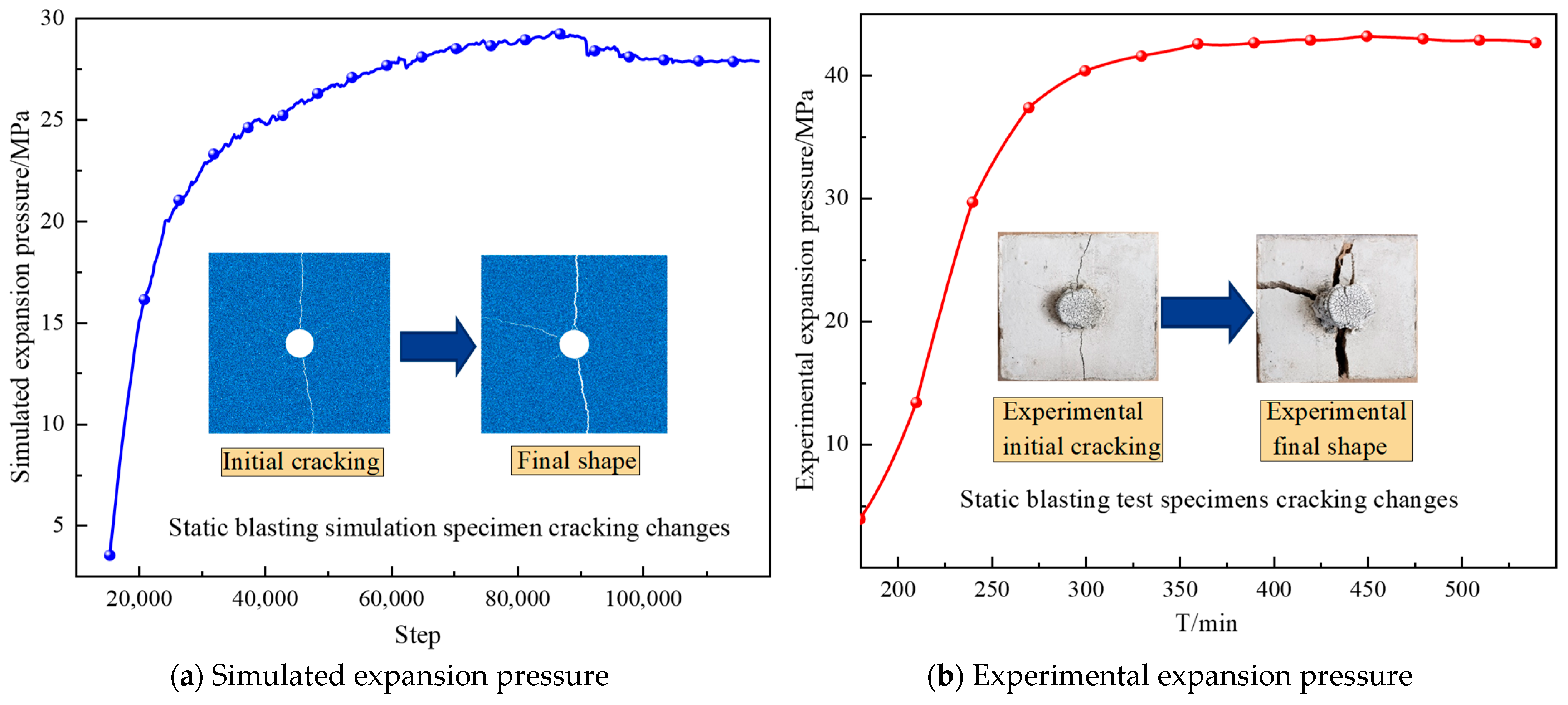
3.1.3. Expansion Pressure Test Result Analysis

Figure 8 illustrates the time-dependent curves depicting the expansion pressure of SCA under steel tubes of different diameters. Figure 9 compares the histograms of peak expansion pressure for SCA under various steel tube diameters, while Figure 10 compares the histograms of the arrival time for the peak expansion pressure. The expansion pressure of SCA increases as the diameter of the steel tube increases. For steel tube diameters of 30 mm, 35 mm, 40 mm, and 45 mm, respectively, the expansion pressures produced by SCA with a water-cement ratio of 0.3 after being submerged in water for 2.5 min are 43.5 MPa, 58.8 MPa, 69.5 MPa, and 75.1 MPa. When the inner diameter is 30 mm, the expansion pressure of SCA is 43.5 MPa, surpassing the typical tensile strength of rocks, which does not exceed 20 MPa. Therefore, theoretically, the expansion pressure generated by SCA is substantial enough to induce cracking in typical rocks. The peak expansion pressure of SCA is reached between 390 min and 550 min.

3.2. Single-Hole Specimen Cracking Test

3.2.1. Single-Hole Specimen Fabrication and Mechanical Parameters

(1)
Specimen mixing ratio
The mortar specimens were divided into four grades (M15, M10, M7.5, and M5.0) based on their compressive strengths, and their mass ratios are displayed in Table 2. In the current experiment, M15 cement mortar was used. The mass ratio for cement, sand, and water in M15 cement mortar is 1.0:3.5:0.6. The specimens were cured for a total of 28 days under the usual curing circumstances.
(2)
Production of single-hole specimens
Before casting the specimen, it is necessary to select the appropriate mold size. In this experiment, a square mold with a side length of 200 mm and a cylindrical mold measuring 50 mm by 100 mm were chosen, as shown in Figure 11. The square mold will be used for the static cracking experiment, while the cylindrical mold will be used for the physical and mechanical parameter tests of the specimen.
When creating single-hole specimens, the use of specimen holes is restricted to prevent any impact on the subsequent static cracking experiments. This is because mechanical drilling can weaken the internal structure and strength of the specimen under certain experimental conditions. The final design of the preset single-hole specimen includes a hole diameter of 35 mm and a hole depth of 125 mm, as illustrated in Figure 12. This design takes into account the size of the concrete specimen and the volume of the drug to ensure precise filling of the holes.
To produce a single-hole specimen, follow these steps:
(a)
Weigh the cement and sand and dry mix them according to the prescribed ratios.
(b)
Add water to the mixture following the prescribed water dosage ratio and thoroughly combine for 10 min.
(c)
Fill the square and cylindrical molds with the mortar mixture until they are filled.
(d)
Place a glue stick in the center of the designated hole in the square mortar, securing it in place.
(e)
Once the mortar has been partially set, remove the molds, take out the glue stick, and store the specimen in a box with consistent humidity and temperature for 28 days.
(f)
Create standard mechanical specimens from the columnar specimens.
Figure 13 illustrates the process of creating single-hole and mechanically determined specimens.
(3)
Measurement of specimen mechanical parameters
To accurately understand the physical and mechanical characteristics of the specimen, the mechanical parameters were measured. The physical and mechanical characteristics of the single-hole specimen are presented in Table 3, obtained through the laboratory’s specimen “compression-(a)-tension-(b)-shear(c)” experiment, as shown in Figure 14.
Consider a single-hole specimen measuring 200 mm × 200 mm × 200 mm. The specimen has a center hole labeled D1 and D2, with a diameter of 35 mm and a depth of 125 mm. In the experiment, a crushing agent was used. A drug roll was soaked in water for 2.5 min, then removed and inserted into the D1 and D2 holes of the specimen. The drug roll was pounded with a stick while observing and recording the decomposition of the specimen. The injection medication volume for the single-hole specimen is illustrated in Figure 15.

3.2.2. Cracking Effect and Analysis of Single-Hole Specimens

The experimental process for each specimen involved recording various parameters, such as the crack initiation time, crack width over time, final number and range of cracks, breaking time, and fracture surface density. This quantitative comparison was conducted to evaluate the cracking effect of each specimen. The crack width of the specimen, which served as the crack initiation mark, was set at 2 mm. The breaking time, defined as the duration from the initiation of cracking until the specimen broke, was measured at this interval. The surface density, calculated as the number of cracks per unit area [39], was determined by dividing the cumulative total length of the cracks by the surface area of the specimen, S, as shown in Equation (14).
A w = l w s
Figure 16 shows the whole cracking process of single-hole specimens D1 and D2. The cracking process of these specimens is roughly the same. There are generally 2–4 cracks in the specimen. The first crack occurs along the minimum resistance line and extends to the free surface. The second crack is the reverse extension of the first crack through the hole, the first crack and second crack are basically on the same line and develop into a through fracture surface. The third crack appears on the hole along the vertical direction of the first crack; occasionally, the third crack passes through the hole to form a fourth crack. However, when the first crack forms a section, the fourth crack does not form throughout the section. With the increasing expansion pressure of the cracking agent, the crack develops and extends, and the crack width increases. Finally, a T-shaped crack is formed on the surface of the cube single-hole specimen, and the specimen is destroyed.
According to the curve in Figure 16 and the factors in Table 4, the width of fractures in the individual single-hole specimens varies over time. In addition to the cracking effect, the drug injection test on average shows a slower effect after approximately 320 min of cracking. The average breaking time of the drug roll effect is around 32 min, indicating a faster break speed. On the curve depicting the changes in crack width over time, the scratch widths of probes D1 and D2 are relatively large, ranging from 23 mm to 39 mm, with an average crack width of 31 mm. The final surface density of cracks ranges from 8.33 m−1. The short soaking time of the drug coil results in low water absorption, slower reaction rate, and lower initial expansion pressure, causing cracks to appear later. However, the low water absorption also leads to a higher peak expansion pressure during the crack expansion stage, which shortens the time it takes for the drug coil to rupture.

4. Numerical Simulation Analysis of Static Blasting Fracturing Influencing Factors

In this section, the PFC2D numerical simulation method is employed to analyze the impact of different hole diameters, hole spacings, and circumferential pressures on the fracturing efficiency of double-hole specimens. The simulation aims to simulate the dynamic effect of the internal mechanics of the specimen, the variation of expansion pressure inside the double hole, and the expansion rule of cracks. This analysis will provide insights into how these factors affect the fracturing efficiency of double-hole specimens.

4.1. Software Calculation Principles and Modeling

The PFC (Particle Flow Code) method is a discrete cell approach that is also known as the particle flow method. It is capable of simulating the motion and interactions of finite-size particles, effectively representing discontinuous physical phenomena like crack propagation and rupture in simulated rock media. This method has been widely used and proven successful in various studies [40,41].

4.1.1. Software Calculation Principles

(1)
Calculation principle
The PFC (Particle Flow Code) particle program analyzes the variations in force and displacement of individual particles. It calculates the displacement of each particle based on Newton’s second law and generates an overall model that represents the internal distribution of stress–strain, crack extension, and other changing rules. The solution procedure of the PFC model is presented in Figure 17 [42].
The mass of the particle is denoted as m i , the combined force acting on it in the direction is represented by F i , and the bending moment and moment of inertia are denoted as I . The initial translational and rotational displacements of the particle are represented by u i and ω i , respectively [43]. The advective and rotational accelerations at a given instant t 0 are calculated using Newton’s second law and are represented as follows:
u i t 0 = F i m
ω i t 0 = M i m
Following is a relationship between the contact force F n and the displacement u n between two particles:
F n = k n × u n
k n —contact stiffness.
(2)
Intrinsic modeling
The PFC particle contact intrinsic model can be categorized into three types: contact stiffness, sliding, and bonding. In the PFC model, particles in contact with each other can form bonds, and the bonding model is further divided into two categories: contact bonding and parallel bonding, based on different bonding ranges. The simulation in this study utilizes the parallel bonding paradigm, as depicted in Figure 18. Table 5 defines each parameter in the parallel bonding model.
(3)
Servo mechanism
The “servo” approach is used to adjust the boundary conditions of the model to maximize contact within the particle zone and achieve equilibrium. This serves as the basis for initiating loading and other simulation activities [44,45]. As shown in Figure 19, the servo speed is continuously adjusted in the horizontal and vertical directions while also calculating the number of particles in contact with the boundary wall. The feedback calculation of the servo parameters for the next time step is then obtained, determining the servo normal speed of the boundary wall in the next time step. This process continues until the adjustment of all boundary walls ensures that the average contact stress of the boundary wall meets the required criteria.

4.1.2. Modeling and Verification

(1)
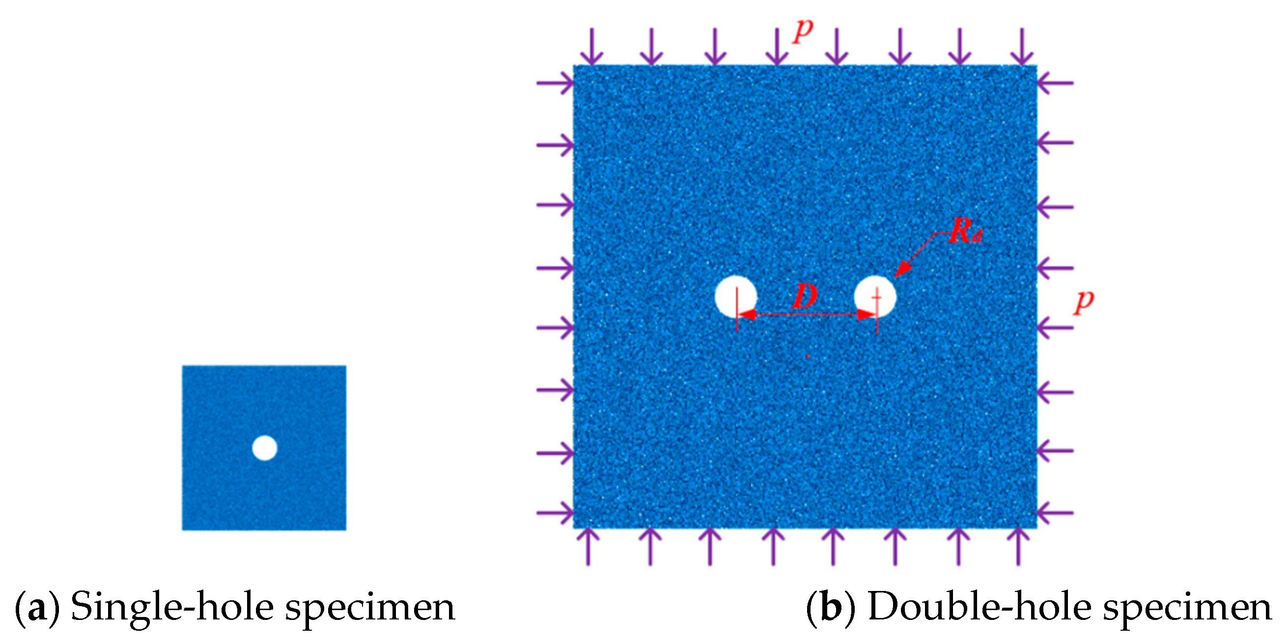
Model size and boundary conditions
To mitigate the formation of drilled holes, a circular wall is strategically positioned, and an additional wall is erected around the periphery to confine the model’s boundaries. These two specimen models were created using PFC2D software, as depicted in Figure 20. The dimensions of the single-hole specimen are 200 mm by 200 mm, while the double-hole specimen measures 1000 mm by 1000 mm. The center hole of the single-hole specimen has a diameter of 30 mm, and there is no circumferential pressure exerted. This specimen serves the purpose of validating the experimental model. The model is subjected to the same peripheral pressure, denoted as p, while the double-hole specimen has a hole diameter Rd and a spacing D. The peak expansion pressure size in the hole, as determined by prior experiments on the expansion pressure of different aperture sizes in the pill volume of actual testing, shall be retained in the simulation of single and double-hole expansion pressure fracture specimens. This simulation involves the utilization of the pill volume and a servo mechanism within the round hole to replicate the expansion pressure of the crusher.
(2)
Calibration and model parameter validation
The model is initially calibrated, as depicted in Figure 21, utilizing parameters from Table 6. This calibration involves simulating a single-hole specimen without peripheral pressure expansion cracking, investigating the development pattern of expansion pressure in a single-hole specimen, and comparing the measured expansion pressure changes obtained from an experiment with steel pipes. The results indicate that the initial increase rate is rapid, followed by a gradual slowdown, suggesting a similar development trend between the simulated and measured expansion pressures. The simulated expansion pressure reaches a maximum of 29.2 MPa, while the experimental expansion pressure reaches a maximum of 43.5 MPa, indicating a disparity between the two maximum expansion pressures. This discrepancy can be attributed to the steel pipe’s ability to maintain its structural integrity and the freedom of expansion pressure to develop, in contrast to the simulated specimen’s crack expansion and the inability of drilled holes to maintain hole integrity, resulting in partial loss of expansion pressure. Consequently, the steel pipe does not require the expansion pressure to reach its maximum at the hole diameter for fracture to occur.
The fracture morphology of the single-hole specimen and the simulated crack extension are depicted in the image, showcasing a remarkable consistency with the laboratory method and results of single-hole expansion cracking. Initially, the specimen exhibits the development of a longitudinal crack along the vertical hole boundary, concurrently generating a transverse crack perpendicular to the longitudinal crack. This transverse crack expands along the path of least resistance towards the free surface. With the progression of expansion pressure, the width of the cracks gradually widens, ultimately resulting in the formation of a T-type damage pattern.
The PFC2D software is capable of simulating the expansion-cracking behavior of specimens, as there is a high similarity between the development of expansion pressure in specimen holes and the cracking and rupture of the specimens. Consequently, the current numerical model enables the simulation of two-hole expansion cracking, enhancing the accuracy of the analysis.

4.1.3. Simulated Experimental Program

The simulation takes into consideration key factors that influence the results, including the variable enclosing pressures at the specified location, as well as the spacing and size of the holes (i.e., the maximum expansion pressure size). The numerical simulation scheme is classified into three categories, which are presented in Table 7.

4.2. Simulation Analysis of Cracking of Double-Hole Specimens with Different Influencing Factors

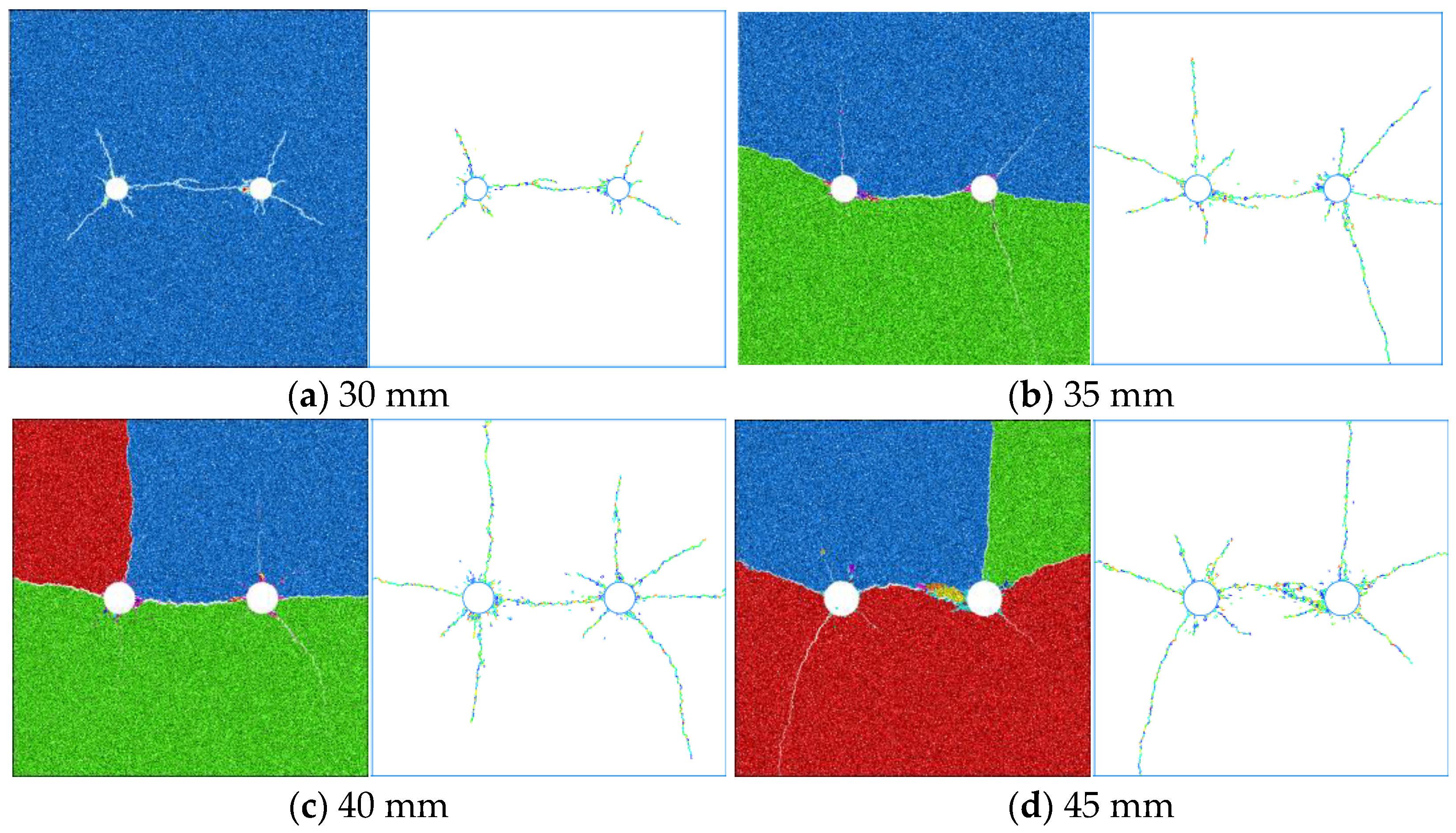
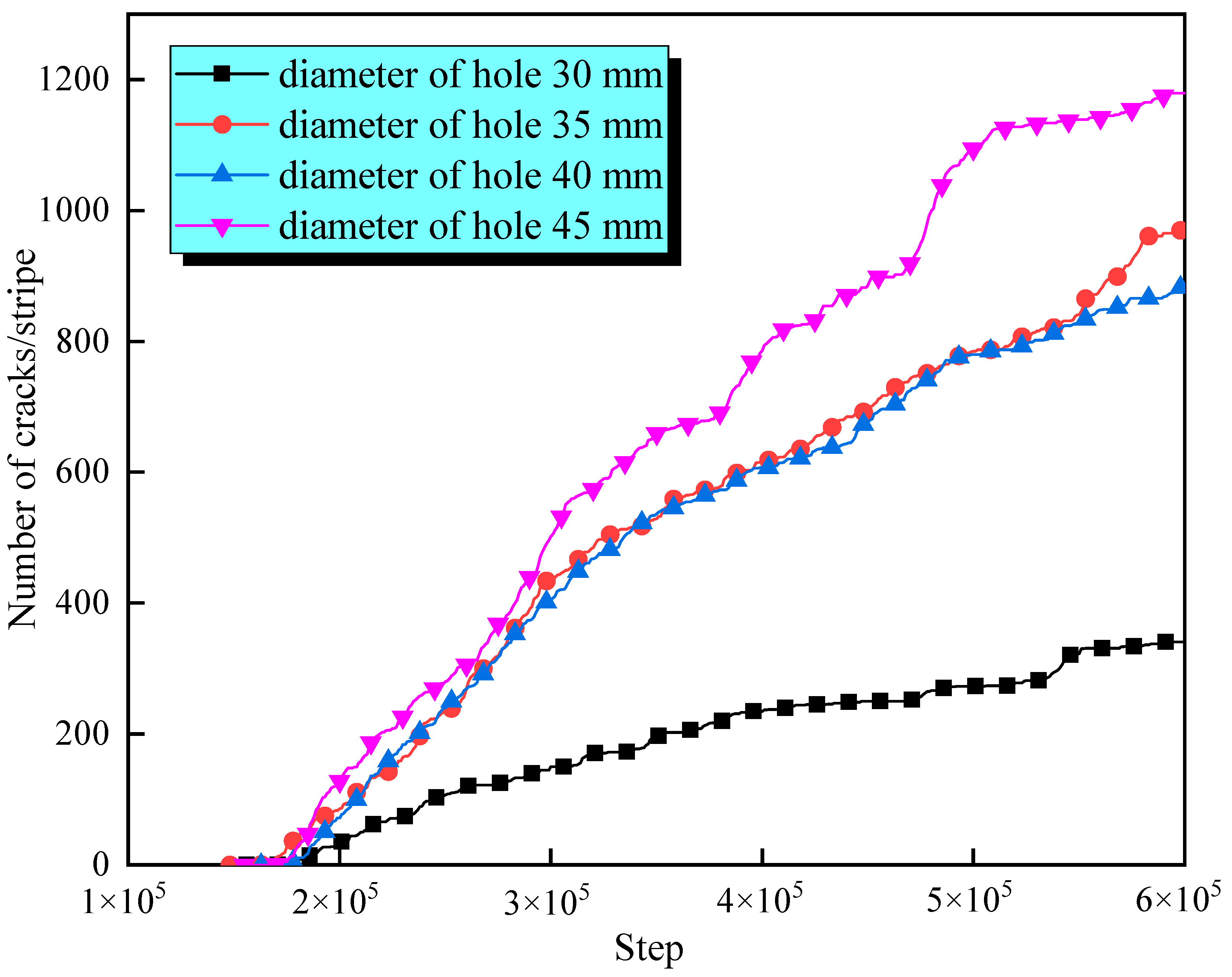
4.2.1. Influence of Pore Size on Specimen Cracking

(1)
Influence of pore size on crack expansion and rupture state of specimens
Figure 22 illustrates the expansion fracture morphology and crack dispersion characteristics of double-hole specimens with different hole diameters. The crack areas of the four specimens are 23.6 mm2, 38.7 mm2, 46.2 mm2, and 77.1 mm2, respectively. This sequence indicates that the size of the hole diameter restricts the fracturing effect and the range of crack expansion, with a positive correlation between the hole diameter and the fracturing effect. As the hole diameter gradually increases, the fracture surface transitions from none to three blocks.
Figure 23 shows the variation in the number of internal cracks in the double-hole specimen under the influence of expansion pressure. The graph reveals that the frequency of cracks increases with an increase in the diameter of the hole. Specifically, as the hole diameter increases from 30 mm to 45 mm, the internal crack count of the specimen grows from 348 to 1180, an approximately 2.4-fold increase, within the same fracturing steps.
(2)
The change rule of expansion pressure and the size of fracturing expansion pressure under different hole diameters
Figure 24 illustrates the change in expansion pressure for each specimen. According to Figure 24a, the peak expansion trend of the specimens is essentially the same, with peak expansion pressures ranging from 38.9 MPa to 46.1 MPa. Figure 24b shows the size of the expansion pressure at the time of double-hole penetration and fracturing. This figure demonstrates that as the pore diameter increases, the connecting distance between the periphery of the double holes becomes shorter. As a result, the crack connection time is reduced, and the required expansion pressure decreases, allowing the crack to expand towards the free surface and form the fracture surface at an earlier stage. This provides further evidence of the positive correlation between the pore size and the impact of fracturing, as a larger pore size enables the extension of the crack towards the free surface, leading to the early formation of the fracture surface.

4.2.2. Influence of Hole Spacing on Specimen Cracking

(1)
Influence of hole spacing on crack expansion and rupture state of specimens
Figure 25 illustrates the impact of different hole spacing on the fracture behavior of double-hole specimens. The crack areas for the three specimens were measured as 43.5 mm2, 38.7 mm2, and 35.2 mm2, respectively. The findings revealed that when the spacing between double holes was small, the stress between the holes was more concentrated, resulting in a faster transfer of tensile stress and quicker extension of the transferring crack. Furthermore, there was a positive correlation observed between the hole spacing and cracking efficiency.
Moving on, Figure 26 displays the variation in the number of internal cracks in double-hole specimens under expansion pressure with different hole spacings. The graph demonstrates a positive relationship between the hole spacing and the time it takes for crack initiation. Conversely, there is a negative correlation between the number of crack expansions and the hole spacing.
(2)
The change rule of expansion pressure under different hole spacing and the size of fracturing expansion pressure
Figure 27 illustrates the change in expansion pressure for double-hole specimens with different hole spacings. Figure 27a shows that the peak expansion trend for each specimen is essentially the same, with the peak expansion pressure ranging from 43.9 MPa to 46.1 MPa.
Furthermore, Figure 27b presents the expansion pressure size at the time of double-hole penetration and at the time of fracturing. It is observed that as the distance between the center holes increases, the crack expansion time between the two holes lengthens. Additionally, a stronger fracturing impact leads to a higher through-expansion pressure.

4.2.3. Influence of Circumferential Pressure on Specimen Cracking

(1)
Influence of circumferential pressure on crack expansion and rupture state of specimens
Figure 28 showcases the expansion fracture shape and crack distribution characteristics of two-hole specimens under different enclosure pressures. The final crack areas for the four specimens were measured as 52.1 mm2, 45.8 mm2, 41.3 mm2, and 38.7 mm2, respectively. It can be observed that as the pressure increases, the fracture surface decreases from 4 to 2. This indicates that the response of the two-hole specimens to expansion fracturing is influenced by the magnitude of the surrounding pressure. Additionally, there is an inverse relationship between the enclosure pressure and the size of the cracks’ expansion range and their degree of fragmentation.
Moving on to Figure 29, it illustrates the relationship between the number of internal cracks in the double-hole specimen and the application of expansion pressure with various peripheral pressures. According to the curve, there is a negative correlation between the peripheral pressure and both the crack initiation time and the crack count in the specimen. Additionally, the growth rate of the number of cracks in each of the four types of specimens follows a similar pattern: initially fast, then slow, and then fast again. The increase in circumferential pressure has an inhibitory effect on the fracture initiation time and the overall number of cracks, but it does not impact the crack growth rate.
(2)
The change rule of expansion pressure and the size of fracturing expansion pressure under different peripheral pressures
Figure 30 portrays the variation in expansion pressure in double-hole specimens under different circumferential pressures. Figure 30a demonstrates that each specimen’s peak expansion development pattern is essentially the same, with a peak expansion pressure ranging from 42.3 MPa to 46.1 MPa.
Furthermore, Figure 30b illustrates the magnitude of the expansion pressure during double-hole penetration and at the time of fracture. It can be observed that the circumferential pressure has a gradient effect on the cracking of double-hole specimens. There is a positive correlation between the perimeter pressure and the expansion pressure at fracture. Additionally, when the perimeter pressure is lowered, there is more unloading of the expansion pressure at the time of the specimen’s rupture, leading to greater fluctuations. This suggests that a high perimeter pressure depletes the specimen’s expansion pressure more, while a low perimeter pressure is more conducive to the extension of the specimen’s crack, resulting in a greater release of expansion potential energy.

5. Discussion

This article explores the mechanical analysis of static cracking agents, elucidating their underlying mechanisms and principles, as well as the dynamics of expansion pressure and rock fracturing. By conducting PFC2D inversion experiments, the feasibility of simulating fractures induced by static cracking agents is demonstrated. The study investigates the internal dynamic effects, crack propagation characteristics, and patterns of expansion pressure development under various aperture sizes, spacing, and confining pressures. This research significantly contributes to enhancing the convenience and timeliness of downhole rock fracturing using explosives. While the existing literature has extensively examined the mechanical mechanisms and crack propagation laws of bulk cracking agents [12,13,24,29,30], this paper specifically highlights the mechanical principles and mechanisms of rolled cracking agents. Rolled static cracking agents (RSCA), compared to traditional bulk static cracking agents (BSCA), generate higher expansion pressure, leading to improved effectiveness and efficiency, especially in rapidly fracturing hard rocks.
The experiments on expansion pressure play a crucial role in determining the effectiveness of static fracture agents [14,15,18]. The magnitude of expansion pressure determines the speed at which rocks are fractured. Previous studies have primarily focused on the impact of different environmental factors on expansion pressure and the resulting expansion laws [17,19,21,22]. However, this study focuses on investigating the variations in expansion pressure and crack propagation laws based on the morphology of the fracture agents themselves. The aim is to enhance the efficiency of rock fracturing, starting from the very source. In a comparative analysis, when the inner diameter of the steel pipe is the same, the RSCA demonstrates an expansion pressure that is 9.5–12.2% higher than the BSCA. For a 30 mm inner diameter, RSCA and BSCA exhibit expansion pressures of 38.2 MPa and 43.5 MPa, respectively. The peak expansion pressure for BSCA occurs between 240 min and 320 min, while for RSCA, it occurs between 390 min and 550 min. It is noteworthy that under the same aperture, BSCA shows a faster hydration reaction, averaging 1.7 times that of RSCA. The crack initiation rate of single-hole specimens under RSCA is lower than that of BSCA, but the former has a higher crack propagation rate than the latter.
The parameters of static fracturing agents play a crucial role in their effectiveness on fractured rock. Most literature analyzes these parameters using numerical simulations, with many scholars employing finite difference methods to simulate rock fracturing [23,24,26,27]. However, these methods cannot visually display crack development patterns. This study utilizes the PFC2D particle flow inversion test process to validate parameter selection and demonstrate the feasibility of simulating static fracturing agents with PFC. It examines internal dynamic effects, crack propagation, and distribution characteristics, as well as the development laws of dual-porosity expansion pressure under different aperture sizes, spacing, and confining pressures. In conclusion, this study provides valuable insights into the fracturing mechanism of RSCA, contributing to improved efficiency in downhole rock fracturing. Nonetheless, it is important to note that the research findings have not yet been applied in real-world applications, and field testing would provide more effective validation of the results.

6. Conclusions

This study conducted RSAC crack propagation experiments and PFC numerical simulations to investigate the principles and mechanisms of static blasting. It aimed to elucidate the characteristics of crack propagation in hard rock under static blasting and analyze the impact of different parameters on crack propagation. The following conclusions were drawn:
(1)
From the perspective of hydration reaction, the study revealed the expansion mechanism and generation of expansion pressure by the fracturing agent. It also examined the mechanical aspects of fracturing hard rock caused by expansion pressure. The results showed a positive correlation between expansion pressure and aperture size. Additionally, the study provided a detailed description of the fracturing processes, including the micro-cracking stage, fissure development stage, and fracture stage in RSAC.
(2)
Using PFC2D software, a numerical model of dual-porosity specimens was established to simulate the expansion fracturing under confining pressure. The simulation revealed internal dynamic effects, microscopic particle motion laws, macroscopic fracture morphology, and crack propagation characteristics during the fracturing process. The study clarified the release of simulated expansion pressure resulting from changes in cracks within the dual-porosity specimens. Furthermore, it determined the magnitude of expansion pressure during complete penetration and rupture of specimens under different conditions.
(3)
The study analyzed the development trends of expansion fracturing in dual-porosity specimens considering various aperture sizes, spacing, and confining pressures. The findings indicated a positive correlation between aperture size and fracturing effect, while spacing and confining pressure exhibited a negative correlation. Moreover, the study revealed a negative correlation between aperture size and the magnitude of expansion pressure, while spacing and confining pressure presented a positive correlation.
The research findings mentioned above significantly contribute to the development of environmentally friendly and efficient methods for fracturing hard rock in underground mining. These findings provide robust evidence regarding the effectiveness of static fracturing agents and introduce a novel approach for rapidly excavating hard rock in coal mines.

Author Contributions

Methodology, Y.C.; Software, S.H.; Formal analysis, L.T.; Writing—original draft, Z.X.; Writing—review & editing, C.L. All authors have read and agreed to the published version of the manuscript.

Funding

This research was funded by National Natural Science Foundation of China (NSFC): 52374140.

Institutional Review Board Statement

Not applicable.

Informed Consent Statement

Not applicable.

Data Availability Statement

All data, models, or codes that support the findings of this study are available from the corresponding author upon reasonable request.

Conflicts of Interest

The authors declare that they have no known competing financial interest or personal relationships that could have appeared to influence the work reported in this paper.

References

  1. Yuan, L.; Zhang, N.; Kan, J.; Wang, Y. The concept, model, and reserve forecast of green coal resources in China. J. China Univ. Min. Technol. 2018, 47, 1–8. [Google Scholar]
  2. Yao, G.; Gao, Z.; Li, X. Evaluation of coal resources bearing capacity in China. China Min. Mag. 2020, 29, 1–7. [Google Scholar]
  3. Lin, B. Strategic Consideration of New Energy Development in China. J. China Univ. Geosci. (Soc. Sci. Ed.) 2018, 18, 76–83. [Google Scholar]
  4. Chen, S.; Feng, F.; Wang, Y.; Li, D.Y.; Huang, W.P.; Zhao, X.D.; Jiang, N. Tunnel failure in hard rock with multiple weak planes due to excavation unloading of in-situ stress. J. Cent. South Univ. 2020, 27, 2864–2882. [Google Scholar] [CrossRef]
  5. Yang, J.; Zheng, K.; Wang, Z.; Pang, N. Technology of weakening and danger-breaking dynamic disasters by hard roof. J. China Coal Soc. 2020, 45, 3371–3379. [Google Scholar]
  6. Li, T.; Zhang, H.; Zhang, Z.; Jia, X.; Sun, G. Deep hole pre-splitting blasting technology when a fully mechanized coal mining face passes through a high drop fault. J. China Coal Soc. 2019, 44, 199–209. [Google Scholar]
  7. Zhang, A.; Yao, G. Static Blasting Construction Technology. Build. Technol. Dev. 2002, 29, 3. [Google Scholar]
  8. You, B. Static Blasting Technology-Silent Breaking Agent and Its Application; China Building Materials Press: Beijing, China, 2008; pp. 1–4. [Google Scholar]
  9. Huang, H. Application and Research of Static Broken Used in High-Gas Coal Mine Roadway End Caving Roof Control. Ph.D. Thesis, Taiyuan University of Technology, Taiyuan, China, 2014. [Google Scholar]
  10. Liu, J.; Zhang, L.; Wei, Y.; Wu, Z. Coupling Model of Stress–Damage–Seepage and Its Application to Static Blasting Technology in Coal Mine. ACS Omega 2021, 6, 34920–34930. [Google Scholar] [CrossRef]
  11. Cui, X.; Zhang, J.; Guo, L.; Gong, X. The Effect of Static Blasting Materials on Coal Structure Changes and Methane Adsorption Characteristics. Adv. Mater. Sci. Eng. 2020, 2020, 2858621. [Google Scholar] [CrossRef]
  12. Jin, Z.; Liao, H.; Zhu, W.; Ma, C.; Liu, Z. Splitting Mechanism of Rock and Concrete Under Expansive Pressure. Chin. J. Rock Mech. Eng. 1989, 1989, 19–26. [Google Scholar]
  13. Zhou, Y.; Shi, S.; Zhang, Y.; Cai, Q.; Liang, J.; Cheng, Y. Fracture and Cut-through Mechanism by Static Controlling Blasting for Rock Breaking. Blasting 2017, 34, 120–125+150. [Google Scholar]
  14. Wang, Y. Research on Mechanism and Technology of No-Explosive Demolition. Ph.D. Thesis, Wuhan University of Technology, Wuhan, China, 2009. [Google Scholar]
  15. Li, R. Static Fracturing Increasing Low Permeability Coal Seam Basic Experiment Research. Ph.D. Thesis, Taiyuan University of Technology, Taiyuan, China, 2017. [Google Scholar]
  16. Gao, Y. Study on Treatment of Hard Roof by Static Crushing Method in High Gassy Mine. Ph.D. Thesis, Taiyuan University of Technology, Taiyuan, China, 2019. [Google Scholar]
  17. Gong, Z.; Ma, Q. Experiment and Analysis of Slit PVC Tube Guiding Soundless Crack Concrete Block. J. Anhui Univ. Sci. Technol. Nat. Sci. 2018, 38, 48–52. [Google Scholar]
  18. Ren, J.; Xie, X.; Zhu, Y. Analysis of Crack Effect by Static Expanding and Cracking Based on Empirical Model of Outburst Coal. Coal Technol. 2015, 34, 153–155. [Google Scholar]
  19. Yang, D. Slow-Release Coal Uncovering in Cross-Cut New Technology by Expanding Agent. Saf. Coal Mines 2013, 44, 58–60. [Google Scholar]
  20. Wang, J. The Association Response Mechanism and Characteristics of Electromagnetic and Microseismic Signals during the Static Cracking Process of Coal or Rock. Ph.D. Thesis, China University of Mining & Technology, Beijing, China, 2015. [Google Scholar]
  21. Hao, B.Y.; Huang, H.; Feng, Z.J.; Wang, K. The Static Breaking Technique for Sustainable and Eco-Environmental Coal Mining. Sci. World J. 2014, 6, 248792. [Google Scholar]
  22. Laefer, D.F.; Ambrozevitch-Cooper, N.; Huynh, M.P.; Midgette, J.; Ceribasi, S.; Wortman, J. Expansive fracture agent behavior for concrete cracking. Mag. Concr. Res. 2010, 62, 443–452. [Google Scholar] [CrossRef]
  23. Tang, X.; Tang, C.; Tang, S.; Cui, Y.; Song, L. Physical experiment and numerical simulation on the effect of the soundless cracking agent. Chin. J. Geotech. Eng. 2005, 27, 437–441. [Google Scholar]
  24. Cheng, X. Study on the Static Expansion Cracking of the Hard Top Plate in the Fully Mechanized Face. Ph.D. Thesis, Xi’an University of Science and Technology, Xi’an, China, 2020. [Google Scholar]
  25. Guo, H.; Zhu, L. Research on the mechanism of energy release and permeability improvement in coal strata by static blasting. China Saf. Sci. J. 2020, 30, 60–65. [Google Scholar]
  26. Li, K. Under the Action of Static Cracking Agent Directional Rupture Plain Concrete Research. Ph.D. Thesis, Anhui University of Science and Technology, Huainan, China, 2016. [Google Scholar]
  27. Zhang, J.; Cui, X.; Zhou, F.; Wang, K.; Xu, S. Numerical Simulation on Crack Radius of Coal Seam Drilling by Static Blasting. Saf. Coal Mines 2017, 48, 146–149. [Google Scholar]
  28. Li, T.; Mou, W.; Yi, R.; Xiao, Q.; Hua, J. Evolution and extension of fissures in hard rocks under double-hole expansion fracturing. Saf. Coal Mines 2021, 52, 70–78. [Google Scholar]
  29. Sabzi, M.; Farzam, M. Hadfield manganese austenitic steel: A review of manufacturing processes and properties. Mater. Res. Express 2019, 6, 1065c2. [Google Scholar] [CrossRef]
  30. Sabzi, M.; Dezfuli, S.M. Post weld heat treatment of hypereutectoid Hadfield steel: Characterization and control of microstructure, phase equilibrium, mechanical properties and fracture mode of welding joint. J. Manuf. Process. 2018, 34, 313–328. [Google Scholar] [CrossRef]
  31. Gao, R.; Kuang, T.; Zhang, Y.; Zhang, W.; Quan, C. Controlling mine pressure by subjecting high-level hard rock strata to ground fracturing. Int. J. Coal Sci. Technol. 2021, 8, 1336–1350. [Google Scholar] [CrossRef]
  32. Chen, F.; Xiong, H.; Wang, X.; Yin, Z. Transmission effect of eroded particles in suffusion using the CFD-DEM coupling method. Acta Geotech. 2023, 18, 335–354. [Google Scholar] [CrossRef]
  33. Yan, G.; Zhang, F.; Ku, T.; Hao, Q.; Peng, J. Experimental Study and Mechanism Analysis on the Effects of Biaxial In-Situ Stress on Hard Rock Blasting. Rock Mech. Rock Eng. 2023, 56, 3709–3723. [Google Scholar] [CrossRef]
  34. Xiong, H.; Zhang, Z.M.; Yang, J.; Yin, Z.Y.; Chen, X.S. Role of inherent anisotropy in infiltration mechanism of suffusion with irregular granular skeletons. Comput. Geotech. 2023, 162, 105692. [Google Scholar] [CrossRef]
  35. Wu, S. Experimental Study on Cracked Coal Seam Hard Roof by Static Cracking Agents. Ph.D. Thesis, China University of Mining & Technology, Xuzhou, China, 2019. [Google Scholar]
  36. Sun, L. Study on the Static Cracking Agent and Its application. Ph.D. Thesis, Xi’an University of Architecture and Technology, Xi’an, China, 2005. [Google Scholar]
  37. Gui, L. Application research of the static cracking technique is used through faulting in synthesis exploitation. China Min. Mag. 2010, 19, 85–87. [Google Scholar]
  38. Li, R.S.; Zheng, W.Z.; Xu, L.B.; Wang, Y. Experimental study on radial expansion compressive stress of steel tube with static crushing agent. J. Harbin Inst. Technol. 2020, 52, 19–27. [Google Scholar]
  39. Zhai, C.; Wu, S.; Tang, Z.; Zhong, C.; Xu, J. Study on seam fracturing and permeability improved technology based on static blasting. Coal Sci. Technol. 2015, 43, 54–57+50. [Google Scholar]
  40. Cheng, P. Research Progress on PFC2D Simulation of Crack Propagation Characteristics of Cracked Rock. J. Eng. Geol. 2018, 26, 528–539. [Google Scholar]
  41. Li, Y.; Cai, W.B.; Li, X.J.; Zhu, W.S.; Zhang, Q.Y.; Wang, S.G. Experimental and DEM Analysis on Secondary Crack Types of Rock-Like Material Containing Multiple Flaws Under Uniaxial Compression. Appl. Sci. 2019, 9, 1749. [Google Scholar] [CrossRef]
  42. Jeong, S.W.; Kighuta, K.; Lee, D.E.; Park, S.S. Numerical Analysis of Shear and Particle Crushing Characteristics in Ring Shear System Using the PFC2D. Materials 2021, 14, 229. [Google Scholar] [CrossRef] [PubMed]
  43. Wang, P.; Yang, T.; Yu, Q.; Liu, H.; Zhang, P. On obtaining jointed rock slope geo-parameters and the application of PFC2D. J. Min. Saf. Eng. 2013, 30, 560–565. [Google Scholar]
  44. Liu, Q.S.; Liu, D.F.; Tian, Y.C.; Liu, X.Y. Numerical simulation of stress-strain behavior of cemented paste backfill in triaxial compression. Eng. Geol. 2017, 231, 165–175. [Google Scholar] [CrossRef]
  45. Shi, C.; Zhang, Q.; Wang, S. Numerical Simulation Techniques and Applications for Particle Flow (PFC5.0); China Building Materials Press: Beijing, China, 2018; pp. 176–186. [Google Scholar]
Figure 1. Diagram illustrating the static crushing agent hydration reaction’s expansion mechanism.
Applsci 13 11310 g001
Figure 2. Analysis of single-hole rock fracturing’s mechanical action.
Applsci 13 11310 g002
Figure 3. Analysis of double-hole rocks’ mechanical fracturing action.
Applsci 13 11310 g003
Figure 4. Multiple free surfaces in rock fractures.
Applsci 13 11310 g004
Figure 5. A schematic representation of a static crusher’s rock fracturing mechanism.
Applsci 13 11310 g005
Figure 6. Diagram of the expansion pressure measurement method.
Applsci 13 11310 g006
Figure 7. Measuring equipment for partial expansion pressure.
Applsci 13 11310 g007
Figure 8. Curves of expansion pressure against time for various pore diameters.
Applsci 13 11310 g008
Figure 9. Size of the static crusher expansion pressure for various hole diameters.
Applsci 13 11310 g009
Figure 10. For various pore diameters, the peak crusher expansion pressure time.
Applsci 13 11310 g010
Figure 11. Schematic diagram of specimen-making mold dimensions (unit: mm).
Applsci 13 11310 g011
Figure 12. Schematic diagram of specimen pre-drilled hole production (unit: mm).
Applsci 13 11310 g012
Figure 13. Specimen production process. (a) mortar mixing; (b) mortar into mold; (c) pre-inserted glue stick; (d) demoulding; (e) single-hole specimen; (f) foundation specimen.
Applsci 13 11310 g013
Figure 14. Physical and mechanical experiments on single-hole specimens. (a) uniaxial compression test; (b) tensile test; (c) shear test.
Applsci 13 11310 g014
Figure 15. Single-hole specimen loading diagram. (a,b) Single-hole RSCA specimen.
Applsci 13 11310 g015
Figure 16. Cracking process and crack width variation with time for each specimen.
Applsci 13 11310 g016
Figure 17. PFC program arithmetic process.
Applsci 13 11310 g017
Figure 18. Parallel bonding model.
Applsci 13 11310 g018
Figure 19. Boundary wall servo mechanism.
Applsci 13 11310 g019
Figure 20. PFC2D numerical modeling.
Applsci 13 11310 g020
Figure 21. Comparison of patterns of change in expansion pressure.
Applsci 13 11310 g021
Figure 22. Expansion cracking pattern and crack distribution characteristics of double-hole specimens with different pore sizes.
Applsci 13 11310 g022
Figure 23. Variation curves of the number of expansion fracture cracks in double-hole specimens with different hole diameters.
Applsci 13 11310 g023
Figure 24. Changing the law of expansion pressure of double-hole specimen under different hole diameters.
Applsci 13 11310 g024
Figure 25. Expansion cracking pattern and crack distribution characteristics of double-hole specimens with a different hole spacing.
Applsci 13 11310 g025
Figure 26. Variation curves of the number of expansion fracture cracks in double-hole specimens with different hole spacings.
Applsci 13 11310 g026
Figure 27. Changing the law of expansion pressure of specimens with different hole spacings.
Applsci 13 11310 g027
Figure 28. Expansion cracking pattern and crack distribution characteristics of double-hole specimens under different circumferential pressures.
Applsci 13 11310 g028
Figure 29. Variation curves of the number of expansion-cracking cracks in double-hole specimens under different circumferential pressures.
Applsci 13 11310 g029
Figure 30. The variation rule of expansion pressure of double-hole specimen with different circumferential pressure.
Applsci 13 11310 g030
Table 1. Measuring expansion pressure specifications for steel pipe with various orifice diameters.
NumberSCALength (mm)Internal Diameter (mm)Outer Diameter (mm)Thicknesses (mm)
H1Herbal medicine roll50030384
H23543
H34048
H44553
Table 2. Quality fit parameters for different grades of strength cement mortar.
Cement Mortar Strength GradeMass of Material Consumed per 1 m³/kgMass RatioMass of Water Used per 1 m³/kg
CementSandCementSand
32.5River Sand32.5River Sand
M15400140013.5270~330
M10330140014.2
M7.5270140015.2
M5.0220140016.4
Table 3. Table of physical and mechanical parameters.
Specimen NumberCompressive Strength (MPa)Elastic Modulus (GPa)Poisson’s RatioTensile Strength (MPa)
113.542.50.161.50
213.972.00.181.23
312.941.60.161.37
Average value13.482.030.171.37
Standard deviation0.7320.6380.0170.191
Table 4. Fracture data table for each single-hole specimen.
Specimen NumberType of SCATime of Crack Initiation (min)Number of CracksRange of Crack Width (mm)Breakage Time (min)Crack Surface Density (m−1)
D1Herbal medicine roll 323328~35348.51
D2319323~39318.15
Standard deviation 2.828 2.1210.255
Table 5. Parallel bonding model parameters.
Parallel Bond Normal StiffnessParallel Bonded Tangential StiffnessParticle Friction CoefficientParallel Bond Normal StrengthParallel Bond Tangential StrengthParticle Contact ModulusParallel Bonded Effective Modulus
k ¯ n k ¯ s μ τ ¯ c σ ¯ c E c E ¯ c
Table 6. PFC2D numerical model parameters.
Particle Size (mm)Density (kg/m3)Young’s Modulus (GPa)Coefficient of FrictionRigidity Ratio
0.5~0.7535001.00.5771
Table 7. Experimental scheme and parameters for simulating expansion cracking in double-hole specimens.
Experimental ProgramDiameter of Hole (mm)Pitch of Hole (mm)Pressurization (MPa)Maximum Expansion Pressure in the Hole (MPa)
30400243.5
3558.8
4069.5
4575.1
3530058.8
400
500
354000.5
1
1.5
2
Disclaimer/Publisher’s Note: The statements, opinions and data contained in all publications are solely those of the individual author(s) and contributor(s) and not of MDPI and/or the editor(s). MDPI and/or the editor(s) disclaim responsibility for any injury to people or property resulting from any ideas, methods, instructions or products referred to in the content.

