
Experimental Study on the Relationship between the Degree of Surrounding Rock Fragmentation and the Adaptability of Anchor Support
 , , , ,
Abstract
:1. Introduction
2. Test Program
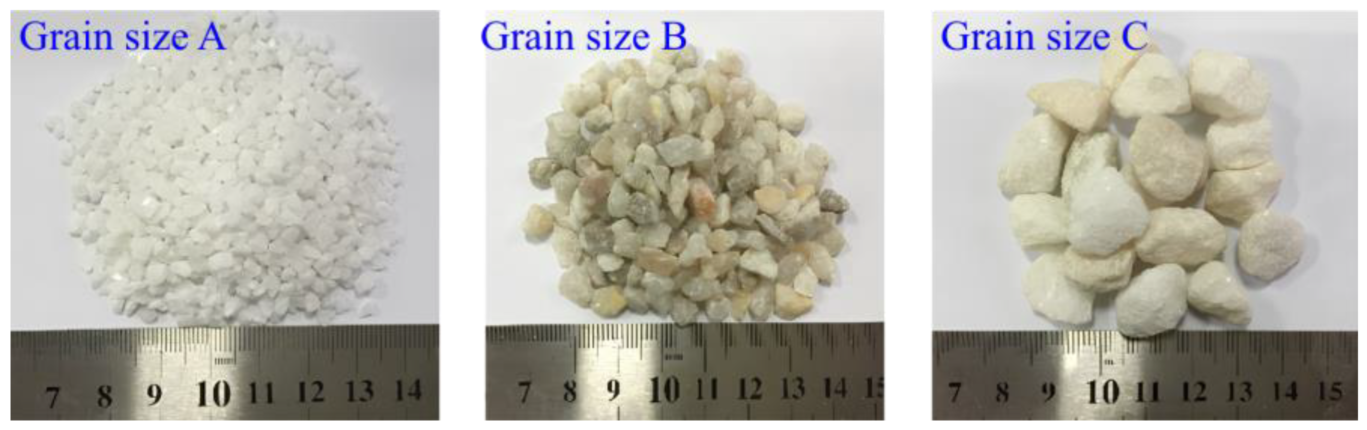
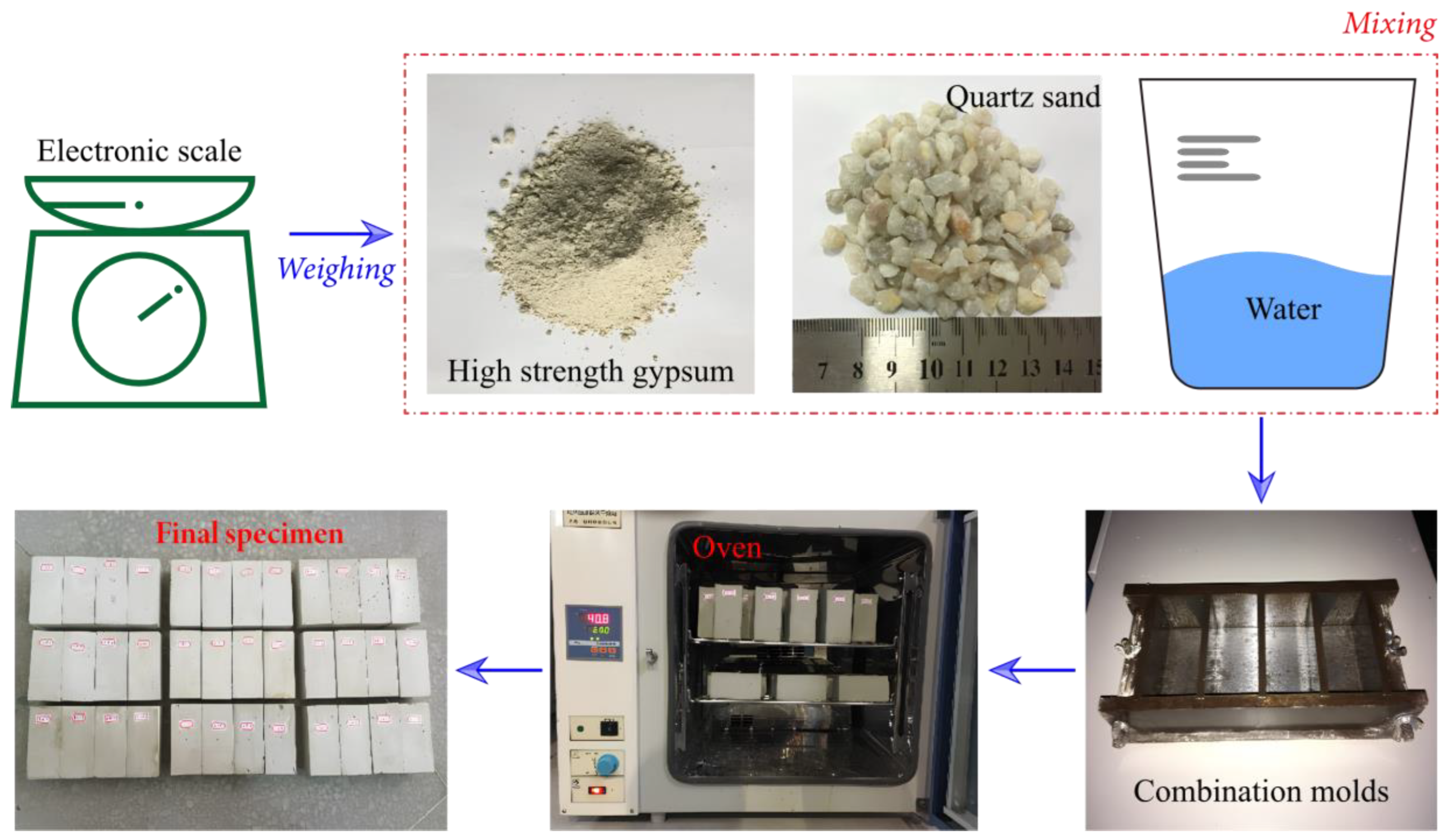
2.1. Modeling
- Brush the mold release agent on the inside of 50 mm × 50 mm × 100 mm mold, weigh quartz sand, gypsum, and water separately with a balance and set aside;
- Put gypsum and quartz sand in a container, add water evenly and mix it quickly, and put it into the mold for vibration (the ratio of materials is water: gypsum: quartz sand = 1:1.5:3);
- Smooth the upper surface after shaking evenly, and remove the mold 24 h after the specimen is finished;
- Put the mixture into the drying box at 60 °C for maintenance, after about 10 days of maintenance drying;
- After the specimen is completely dry, polish the specimen and measure with vernier calipers to ensure that the error is within the allowable range.
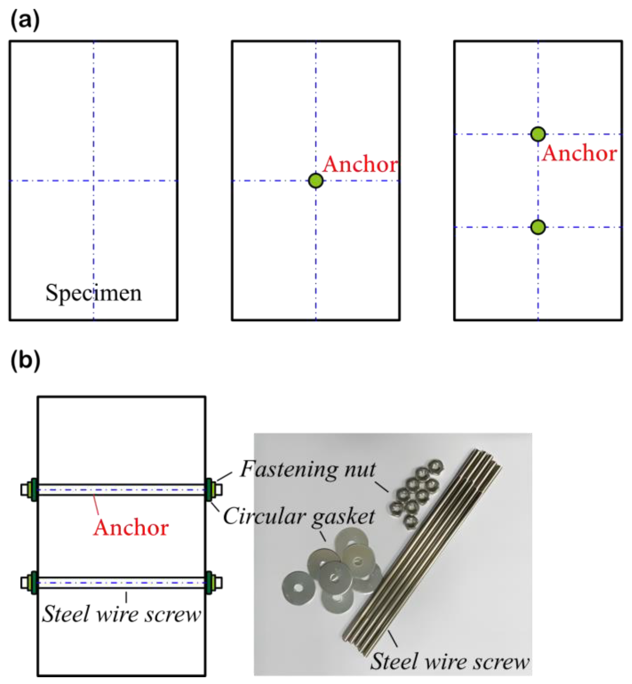
2.2. Test Methods
3. Results
3.1. Stress–Strain Curve of Anchor Solid
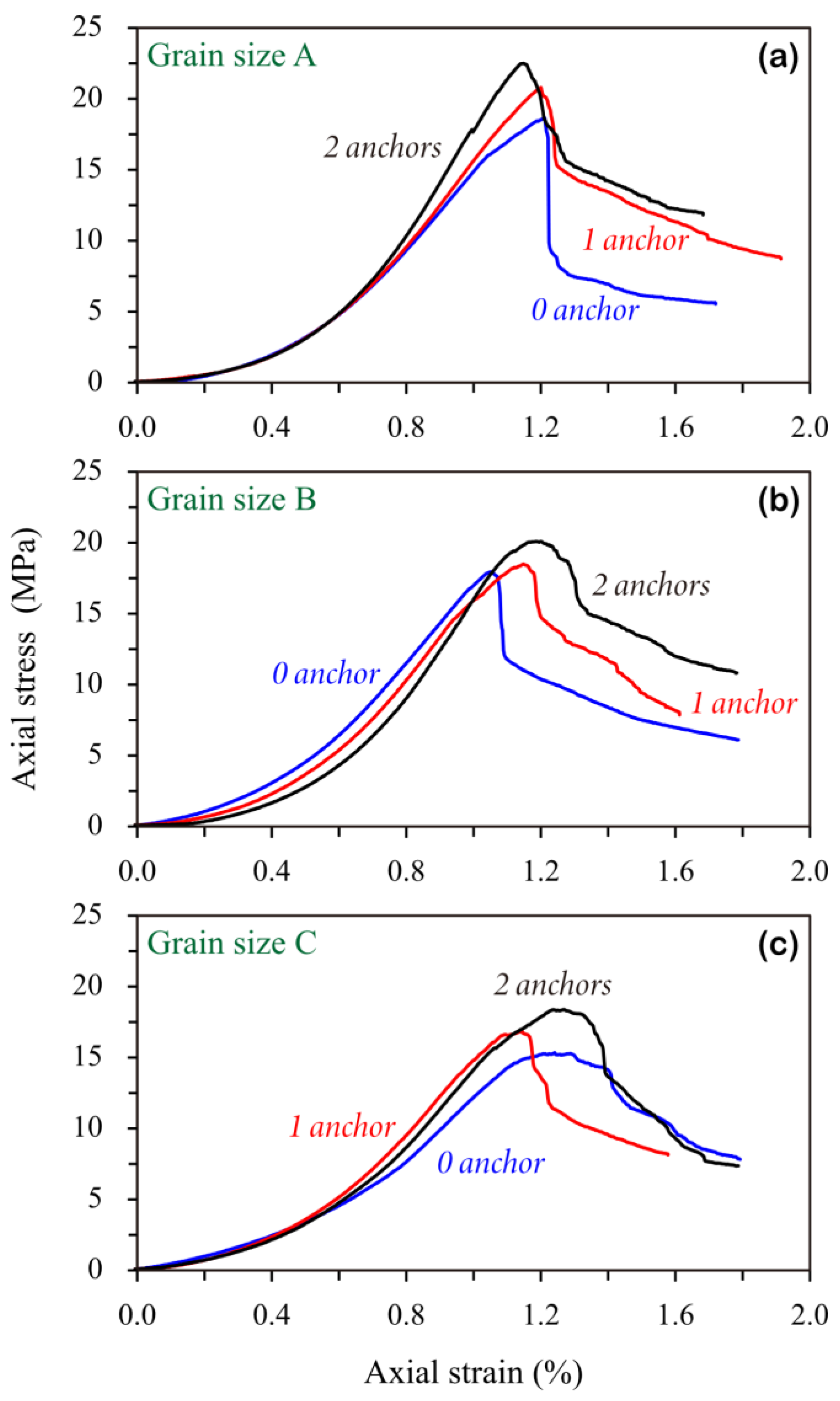
- The uniaxial compressive strength and modulus of elasticity of the specimens showed the following pattern: small-size aggregate specimen > medium-size aggregate specimen > large-size aggregate specimen. The average compressive strength of the unanchored specimens with 2–4 mm aggregate (Grain size A) was 19.75 MPa, that of the unanchored specimens with 4–8 mm aggregate (Grain size B) was 18.30 MPa, and that of the unanchored specimens with 10–15 mm aggregate (Grain size C) was 16.94 MPa. Uniaxial compressive strength decreased by 7.34% and 14.23%, respectively. The average modulus of elasticity of the unanchored specimens with 2–4 mm aggregate was 3.074 GPa, the average modulus of elasticity of the unanchored specimens with 4–8 mm aggregate was 2.884 GPa, and that of the unanchored specimens with 10–15 mm aggregate was 2.549 GPa, with the modulus of elasticity decreasing by 6.18% and 17.06%, respectively.
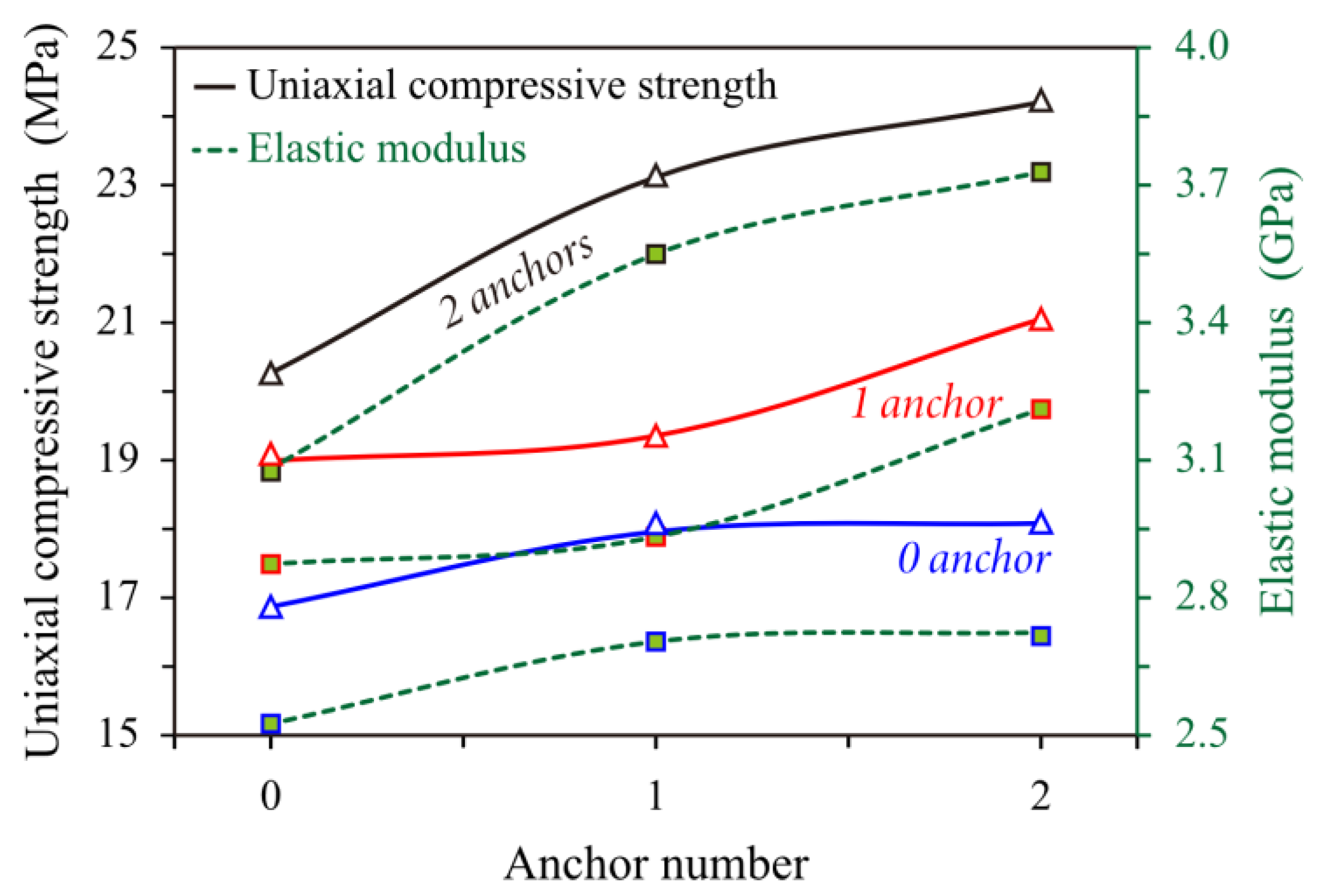
- The anchoring effect of the anchors on the specimens of different grain sizes varied. For the specimens with different grain sizes of the aggregates with the different anchoring methods, the uniaxial compressive strength and elastic modulus of the specimens followed this pattern: no anchor < single anchor < double anchor. Among them, the uniaxial compressive strength of the specimens with 2–4 mm aggregate size increased by 12.90% and 22.81%, and the modulus of elasticity increased by 16.39% and 23.34%, respectively, compared with that without the anchor in the single-anchored and double-anchored specimens; the uniaxial compressive strength of the specimens with 4–8 mm aggregate size increased by 4.16% and 11.35%, and the modulus of elasticity increased by 3.33% and 14.34%, respectively, compared with that without the anchor in the single-anchored and double-anchored specimens, which increased by 3.33% and 14.25%; the specimens with 10–15 mm particle size aggregate increased the uniaxial compressive strength by 4.88% and 6.02% and the modulus of elasticity by 7.19% and 9.16%, respectively, when the single and double anchored were compared to the unanchored.
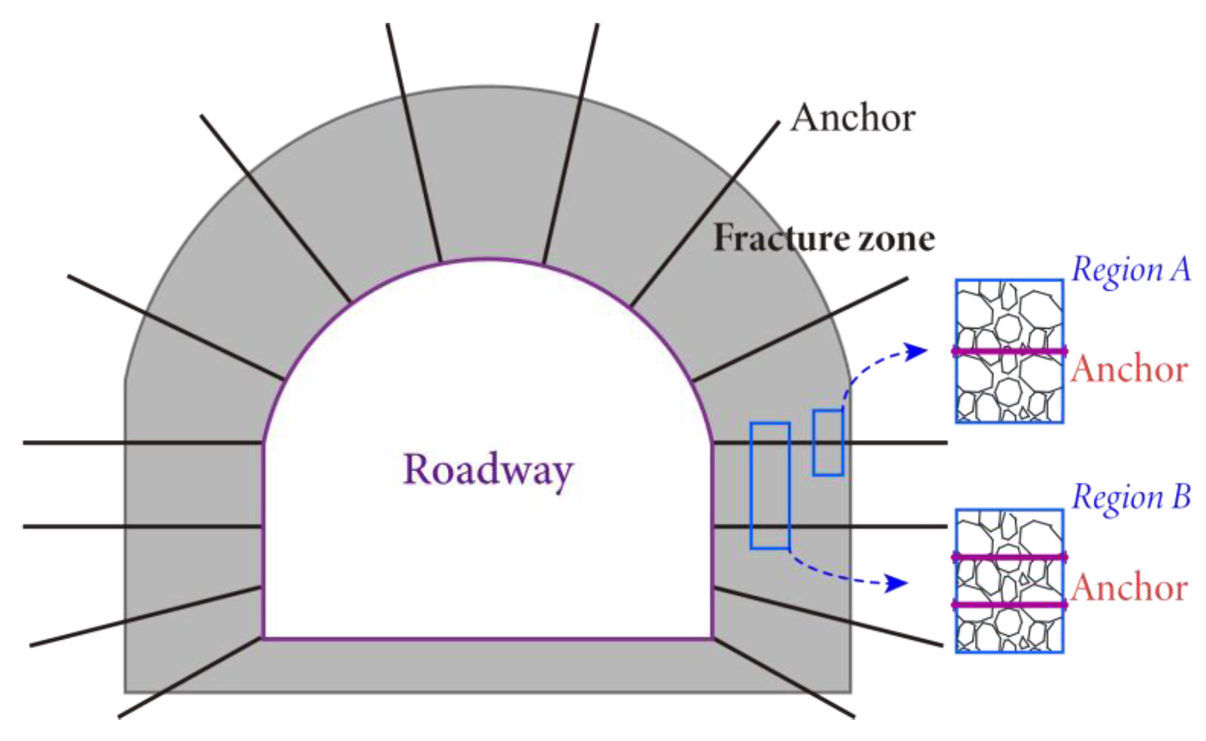
- With the increase in the specimen aggregate particle size, the degree of improvement of the mechanical properties of the anchor rods on the specimen gradually decreased, due to the formation of large-size aggregate and the gypsum size of the structural surface. Because the specimen crushing degree was larger, the anchoring effect of the anchor rods could not be given full play in the crushed rock, and the anchor rods on the crushed rock support adaptability was reduced. Therefore, under the condition of roadways surrounded by rock with a high degree of crushing, auxiliary support measures need to be taken to form a joint coordinated support form to control the phenomenon of a poor anchor support effect of the crushed surrounding rock, the large deformation of roadways surrounded by rock, and other phenomena affecting the safe production of the mine.
3.2. Rupture Characteristics
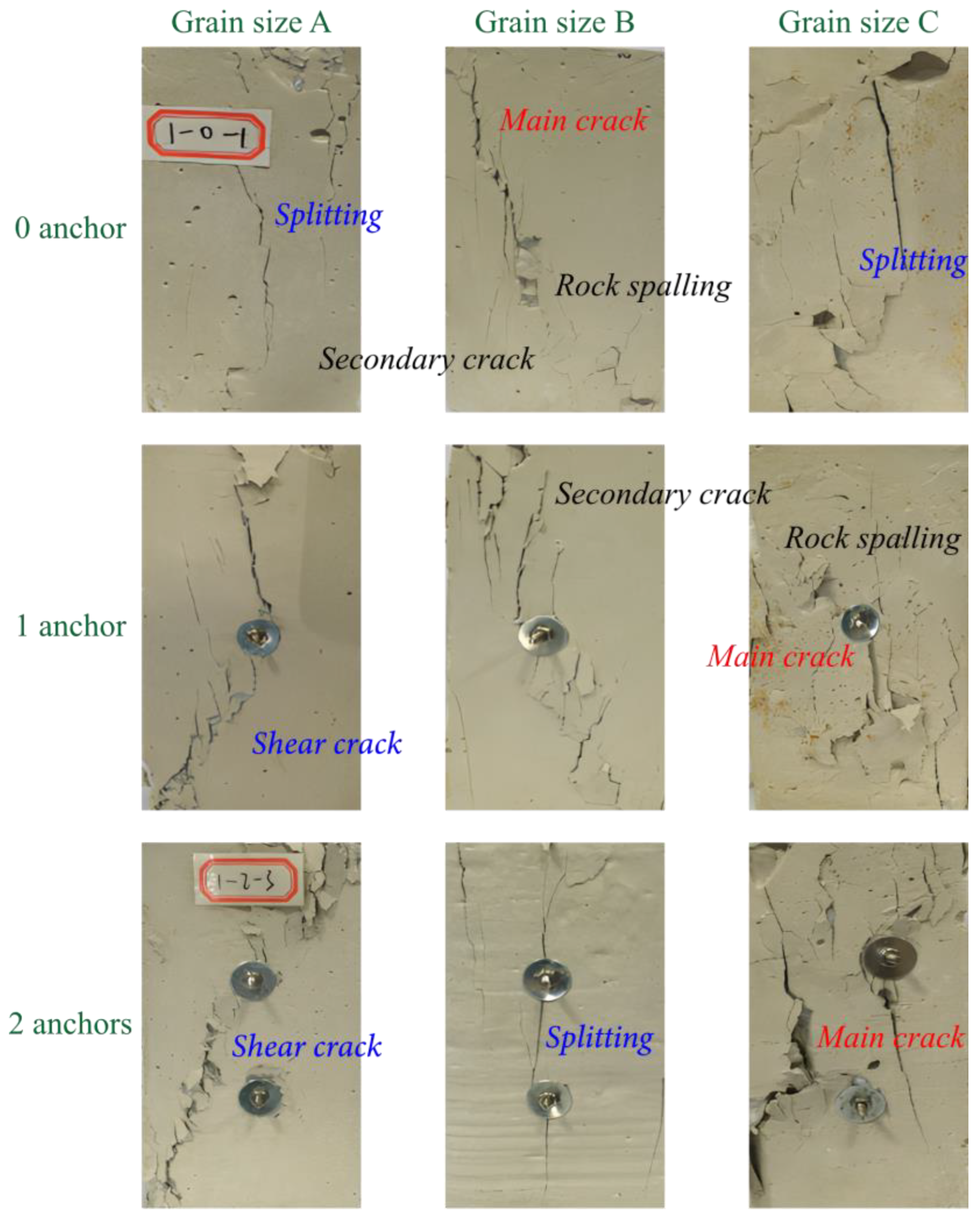
- Under the condition of no anchor (0 anchor), the uniaxial compression of the specimen formulated with large-grained aggregate was more serious than that of the small-grained aggregate specimen. The specimen as a whole showed diagonal shear damage, but the secondary fissures showing splitting damage developed to a high degree, and different sizes of block spalling phenomenon appeared. When the aggregate diameter was 2–4 mm (Grain size A), the specimen split along the axial direction, i.e., the morphology of the rupture surface was parallel to the loading axial direction, and no shear rupture occurred; when the aggregate diameter was 4–8 mm (Grain size B), the shear rupture was relatively slight, and the shear rupture surface was not completely through the upper and lower parts of the rupture surface; and when the aggregate diameter was 10–15 mm (Grain size C), obvious shear damage occurred on the free surface, and a large number of block spalling phenomenon occurred. This shows the strength difference of the specimens made of the aggregates with different grain size ratios.
- Under the action of the single anchor (1 anchor), the rock body along the anchor direction was subjected to a certain support resistance constraint, and the rupture of the specimen was relatively homogenized. The rupture crack direction of the rock body changed, the main rupture cracks in the aggregate diameter of 2–4 mm and 4–8 mm rupture cracks in the anchor position rupture crack direction changed at a certain angle, compared with the no-anchor condition rupture degree, which was small; 10–15 mm aggregate single-anchor specimens produced intensive rupture cracks, appearing to a certain extent of the block exfoliation. Combined with the rupture surface of the specimen under the anchored condition in Figure 8, the anchoring effect of the anchor on the specimen was reflected in the two aspects of reinforcement and crack stopping. Under the pre-stressing effect of the anchor, when the crack developed to the range of the anchor’s action, the anchor played the role of stopping the crack from developing or changing the direction. The role of the tray along the anchor axial force was applied, and when the tray was in contact with the formation of conical stress concentration within the rock mass, the rock mass played a reinforcing effect.
- Under the double-anchor condition (2 anchors), the damage pattern of the anchored rock body, when compared with single anchor with an aggregate diameter of 2–4 mm, had less developed specimen secondary cracks; when the aggregate diameter was 4–8 mm, the main rupture cracks were distributed along the direction of the axial stress, and the specimen underwent splitting damage, and the secondary cracks were obviously reduced. When the aggregate diameter was 10–15 mm, the rupture cracks produced by the single-anchor specimen are greater. When the aggregate diameter was 10–15 mm, the rupture cracks produced by the single-anchor specimens were intensive, and those produced by the double-anchor specimens were relatively scattered. This shows that the increase in anchors effectively enhanced the cementation between the anchors and the rock body, which can augment the supporting role of anchors, thus alleviating the degree of rupture of the rock body and improving the overall bearing capacity.
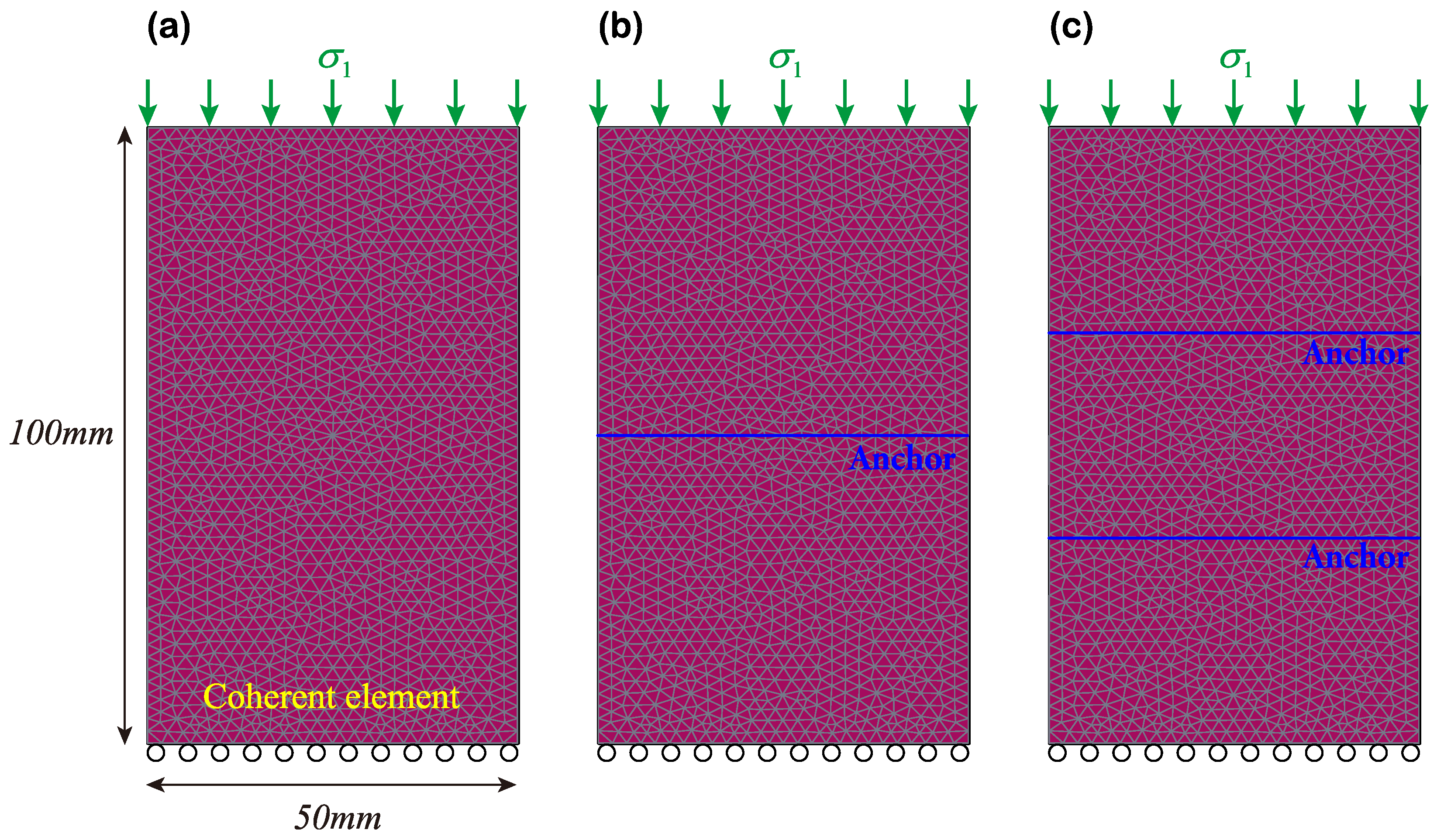
4. Numerical Modeling
5. Discussion of the Results
6. Conclusions
- The uniaxial compressive strength of the specimens with different grain size quartz sand as the aggregate showed significant differences, with a smaller surface area for the smaller grain size quartz sand aggregate, a smaller contact surface for gypsum, which formed smaller size structural surfaces inside the specimen and had a smaller degree of fragmentation, whereas the larger grain size quartz sand aggregate formed larger size structural surfaces inside the specimen and a higher degree of fragmentation. The uniaxial compressive strength and modulus of elasticity of the specimens showed the following pattern: small-size aggregate specimen > medium-size aggregate specimen > large-size aggregate specimen.
- Compared with the specimen without the anchor, the residual strength value of the anchored specimen in the late stage of damage had a greater increase, but the residual strength value was higher than that of the large aggregate specimen in the compression process of the small aggregate specimen, and the trend of the stress–strain curve close to the horizontal direction was more obvious in the specimen of the larger aggregate size. This shows that under uniaxial compression, the anchor can not only improve the compressive strength and elastic modulus of the rock mass but it can also improve the residual strength of the rock mass. However, with the increase in specimen crushing degree, the ability of the anchor to improve the residual strength of the rock mass gradually decreased.
- The anchoring effect of the anchors on the specimens with different grain sizes varies was crucial. When different anchoring methods are used for the specimens with the different grain sizes of the aggregates, the uniaxial compressive strength and elastic modulus of the specimens follow the following pattern: no anchor<single anchor<double anchor. With the increase in the specimen aggregate size, the degree of improvement of the mechanical properties of the specimens by the anchors decreases gradually.
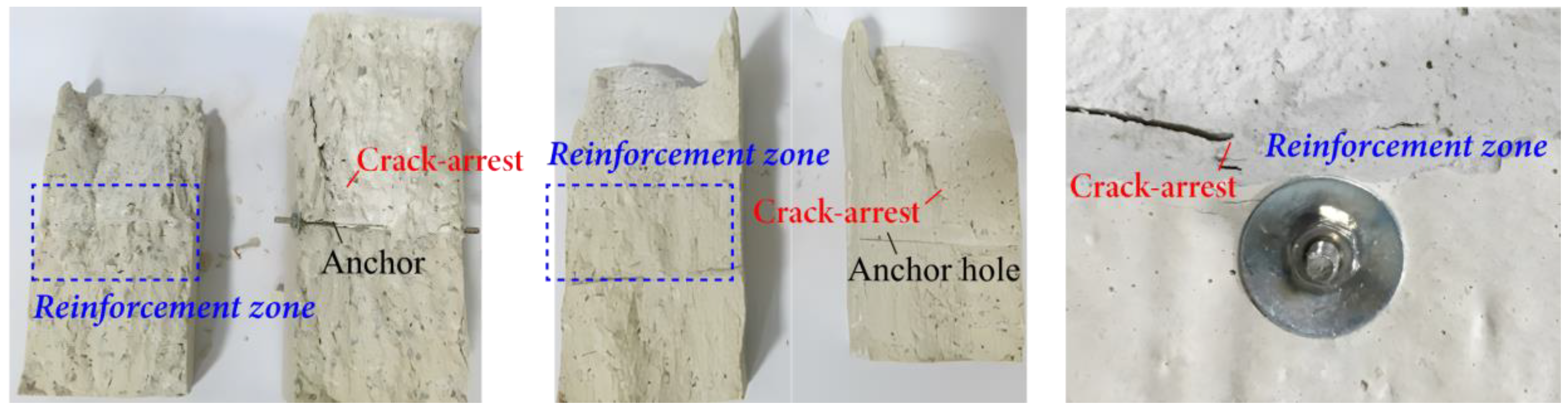
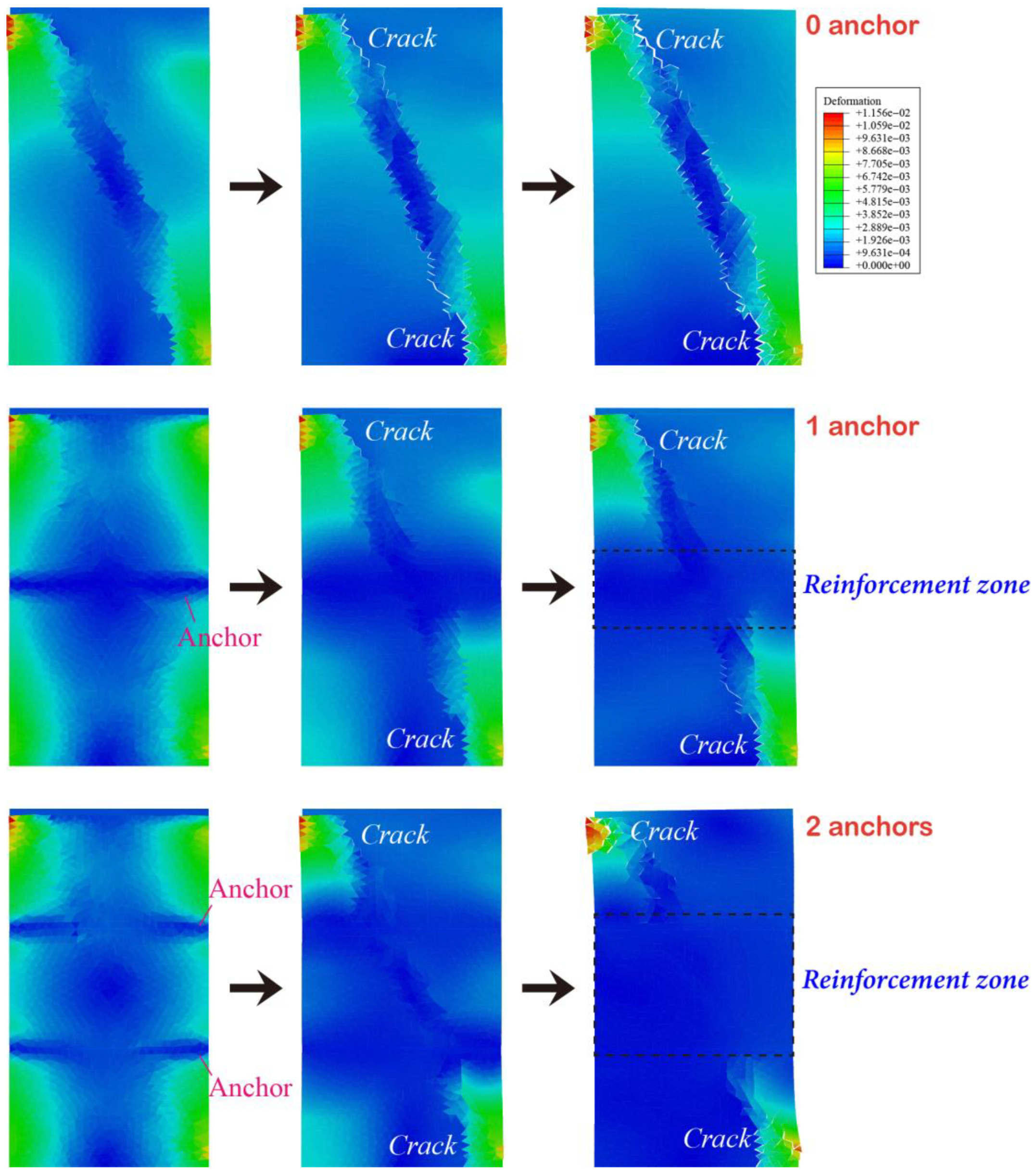
- Numerical tests on the uniaxial compression of the rock containing cohesive units were carried out. It was found that under the no-anchor condition, the specimen showed typical oblique shear damage characteristics, and under the single-anchor action, the deformation of the specimen near the anchor bar was obviously reduced. By contrast, the main rupture surface was blocked, and an obvious reinforcement zone was formed near the anchor bar. Under the double-anchor condition, the anchor tension stress was more obvious, the reinforcement zone was wider, and the rock rupture surface was strongly blocked, all of which made its reinforcement effect the more obvious.
- The anchoring effect of the anchor on the specimen was reflected in the two aspects of reinforcement and crack stopping. Under the prestressing effect of the anchor, when the crack developed to the range of the anchor’s action, the anchor played the role of stopping the crack from developing or changing its direction. After the specimen rupture, an obvious conical reinforcement zone was formed at the anchor reinforcement, and this extrusion reinforcement effect improved the integrity and bearing capacity of the rock mass. Moreover, the denser the anchors, the wider the reinforcement zone, and the superposition effect occurred, which better utilized the supporting role of the anchors and played a key role in stabilizing the rock.
Author Contributions
Funding
Institutional Review Board Statement
Informed Consent Statement
Data Availability Statement
Conflicts of Interest
References
- Kang, H. Support technologies for deep and complex roadways in underground coal mines: A review. Int. J. Coal Sci. Technol. 2014, 1, 261–277. [Google Scholar] [CrossRef]
- He, M.C. Rock mechanics and hazard control in deep mining engineering in China. Rock Mech. Undergr. Constr. 2006. [Google Scholar] [CrossRef]
- Sun, J.; Wang, S. Rock mechanics and rock engineering in China: Developments and current state-of-the-art. Int. J. Rock Mech. Min. Sci. 2000, 37, 447–465. [Google Scholar] [CrossRef]
- Xie, H.; Lu, J.; Li, C.; Li, M.; Gao, M. Experimental study on the mechanical and failure behaviors of deep rock subjected to true triaxial stress: A review. Int. J. Min. Sci. Technol. 2022, 32, 915–950. [Google Scholar] [CrossRef]
- Xie, H.; Gao, F.; Ju, Y. Research and development of rock mechanics in deep ground engineering. Chin. J. Rock Mech. Eng. 2015, 34, 2161–2177. [Google Scholar]
- Chai, Y.; Dou, L.; Cai, W.; Małkowski, P.; Li, X.; Gong, S.; Bai, J.; Cao, J. Experimental investigation into damage and failure process of coal-rock composite structures with different roof lithologies under mining-induced stress loading. Int. J. Rock Mech. Min. Sci. 2023, 170, 105479. [Google Scholar] [CrossRef]
- Yoon, S.; Lee, H.; Kim, J. The modeling of fault activation, slip, and induced seismicity for geological CO2 storage at a pilot-scale site in the Janggi Basin, South Korea. Int. J. Rock Mech. Min. Sci. 2023, 170, 105441. [Google Scholar] [CrossRef]
- Ju, Y.; Zhang, Q.; Yang, Y.; Xie, H.; Gao, F.; Wang, H. An experimental investigation on the mechanism of fluid flow through single rough fracture of rock. Sci. China Technol. Sci. 2013, 56, 2070–2080. [Google Scholar] [CrossRef]
- Yin, Q.; Jing, H.; Zhu, T. Mechanical behavior and failure analysis of granite specimens containing two orthogonal fissures under uniaxial compression. Arab. J. Geosci. 2015, 9, 31. [Google Scholar] [CrossRef]
- Lee, H.; Jeon, S. An experimental and numerical study of fracture coalescence in pre-cracked specimens under uniaxial compression. Int. J. Solids Struct. 2011, 48, 979–999. [Google Scholar] [CrossRef]
- Zhang, B.; Li, S.; Yang, X.; Zhang, D.; Shao, C.; Yang, W. Uniaxial compression tests on mechanical properties of rock mass similar material with cross-cracks. Rock Soil Mech. 2012, 33, 3674–3679. [Google Scholar]
- Wu, W.; Gong, F.; Ren, L.; He, L. Strain rockburst failure characteristics and mechanism of high stress circular hard rock tunnel triggered by dynamic impact load. Int. J. Rock Mech. Min. Sci. 2023, 171, 105575. [Google Scholar] [CrossRef]
- Jeon, S.; Kim, J.; Seo, Y.; Hong, C. Effect of a fault and weak plane on the stability of a tunnel in rock—A scaled model test and numerical analysis. Int. J. Rock Mech. Min. Sci. 2004, 41, 658–663. [Google Scholar] [CrossRef]
- Moir, H.; Lunn, R.J.; Shipton, Z.K.; Kirkpatrick, J.D. Simulating brittle fault evolution from networks of pre-existing joints within crystalline rock. J. Struct. Geol. 2010, 32, 1742–1753. [Google Scholar] [CrossRef]
- Wang, J.; Apel, D.B.; Xu, H.; Wei, C.; Skrzypkowski, K. Evaluation of the Effects of Yielding Rockbolts on Controlling Self-Initiated Strainbursts: A Numerical Study. Energies 2022, 15, 2574. [Google Scholar] [CrossRef]
- Wang, Q.R.; Xie, L.X.; Song, E.X.; Kong, F.L.; Fan, J.Q.; Yu, L.Y.; Xu, J.M.; Shi, X.Y. Model tests on dynamic responses of surrounding rock and support structure on underground tunnel under combined dynamic and static loading. Int. J. Rock Mech. Min. Sci. 2023, 171, 105572. [Google Scholar] [CrossRef]
- Li, C.C.; Stjern, G.; Myrvang, A. A review on the performance of conventional and energy-absorbing rockbolts. J. Rock Mech. Geotech. Eng. 2014, 6, 315–327. [Google Scholar] [CrossRef]
- Kang, H.; Wu, Y.; Gao, F.; Jiang, P.; Cheng, P.; Meng, X.; Li, Z. Mechanical performances and stress states of rock bolts under varying loading conditions. Tunn. Undergr. Space Technol. 2016, 52, 138–146. [Google Scholar] [CrossRef]
- Huang, Z.; Broch, E.; Lu, M. Cavern roof stability—Mechanism of arching and stabilization by rockbolting. Tunn. Undergr. Space Technol. 2002, 17, 249–261. [Google Scholar] [CrossRef]
- Skrzypkowski, K.; Korzeniowski, W.; Zagórski, K.; Dudek, P. Application of Long Expansion Rock Bolt Support in the Underground Mines of Legnica–Głogów Copper District. Stud. Geotech. Et Mech. 2017, 39, 47–57. [Google Scholar] [CrossRef]
- Cao, R.; Cao, P.; Lin, H. Support technology of deep roadway under high stress and its application. Int. J. Min. Sci. Technol. 2016, 26, 787–793. [Google Scholar] [CrossRef]
- Chen, Y.; Meng, Q.; Xu, G.; Wu, H.; Zhang, G. Bolt-grouting combined support technology in deep soft rock roadway. Int. J. Min. Sci. Technol. 2016, 26, 777–785. [Google Scholar] [CrossRef]
- Chen, S.H.; Yang, Z.M.; Wang, W.M.; Shahrour, I. Study on Rock Bolt Reinforcement for a Gravity Dam Foundation. Rock Mech. Rock Eng. 2012, 45, 75–87. [Google Scholar] [CrossRef]
- Wang, J.; Li, S.-C.; Li, L.-P.; Zhu, W.; Zhang, Q.-Q.; Song, S.-G. Study on anchorage effect on fractured rock. Steel Compos. Struct. 2014, 17, 791–801. [Google Scholar] [CrossRef]
- Zhang, B.; Li, S.; Xia, K.; Yang, X.; Zhang, D.; Wang, S.; Zhu, J. Reinforcement of rock mass with cross-flaws using rock bolt. Tunn. Undergr. Space Technol. 2016, 51, 346–353. [Google Scholar] [CrossRef]
- Wang, J. New development of rock bolting technology for coal roadway in China. J. China Coal Soc. 2007, 32, 113–118. [Google Scholar]
- Liu, Q.; Lei, G.; Peng, X. Advance and review on the anchoring mechanism in deep fractured rock mass. Chin. J. Rock Mech. Eng. 2016, 35, 312–332. [Google Scholar]
- Li, S.; Zhang, N.; Lu, A.; Li, M.; Yang, L. Experimental study of anchoring effect of discontinuous jointed rock mass under uniaxial tension. Chin. J. Rock Mech. Eng. 2011, 30, 1579–1586. [Google Scholar]
- Chen, Y. Experimental study and stress analysis of rock bolt anchorage performance. J. Rock Mech. Geotech. Eng. 2014, 6, 428–437. [Google Scholar] [CrossRef]
- Sagong, M.; Bobet, A. Coalescence of multiple flaws in a rock-model material in uniaxial compression. Int. J. Rock Mech. Min. Sci. 2002, 39, 229–241. [Google Scholar] [CrossRef]
- Su, H.; Jing, H.; Zhao, H.; Yu, L.; Wang, Y. Strength degradation and anchoring behavior of rock mass in the fault fracture zone. Environ. Earth Sci. 2017, 76, 179. [Google Scholar] [CrossRef]
- Jing, H.W.; Yang, S.Q.; Zhang, M.L.; Xu, G.A.; Chen, K.F. An experimental study on anchorage strength and deformation behavior of large-scale jointed rock mass. Tunn. Undergr. Space Technol. 2014, 43, 184–197. [Google Scholar] [CrossRef]
- Deb, D.; Das, K.C. A new doubly enriched finite element for modelling grouted bolt crossed by rock joint. Int. J. Rock Mech. Min. Sci. 2014, 70, 47–58. [Google Scholar] [CrossRef]
- Nie, W.; Zhao, Z.; Ning, Y.; Sun, J. Development of rock bolt elements in two-dimensional discontinuous deformation analysis. Rock Mech. Rock Eng. 2014, 47, 2157–2170. [Google Scholar] [CrossRef]
- Lin, H.; Xiong, Z.; Liu, T.; Cao, R.; Cao, P. Numerical simulations of the effect of bolt inclination on the shear strength of rock joints. Int. J. Rock Mech. Min. Sci. 2014, 66, 49–56. [Google Scholar] [CrossRef]
- Grasselli, G. Manuel Rocha Medal Recipient Shear Strength of Rock Joints Based on Quantified Surface Description. Rock Mech. Rock Eng. 2006, 39, 295. [Google Scholar] [CrossRef]
- Lee, J.S.; Bang, C.S.; Mok, Y.J.; Joh, S.H. Numerical and experimental analysis of penetration grouting in jointed rock masses. Int. J. Rock Mech. Min. Sci. 2000, 37, 1027–1037. [Google Scholar] [CrossRef]
- Fan, L.; Liu, S. A conceptual model to characterize and model compaction behavior and permeability evolution of broken rock mass in coal mine gobs. Int. J. Coal Geol. 2017, 172, 60–70. [Google Scholar] [CrossRef]
- Li, S.C.; Wang, Q.; Wang, H.T.; Jiang, B.; Wang, D.C.; Zhang, B.; Li, Y.; Ruan, G.Q. Model test study on surrounding rock deformation and failure mechanisms of deep roadways with thick top coal. Tunn. Undergr. Space Technol. 2015, 47, 52–63. [Google Scholar] [CrossRef]
- Brown, E.T. (Ed.) Rock Characterization, Testing & Monitoring: ISRM Suggested Methods; International Society for Rock Mechanics, Pergamon Press: Oxford, UK, 1981. [Google Scholar]
- Fairhurst, C.E.; Hudson, J.A. Draft ISRM suggested method for the complete stress-strain curve for intact rock in uniaxial compression. Int. J. Rock Mech. Min. Sci. 1999, 36, 279–289. [Google Scholar]
- Wang, S.; Wang, L.G.; Tian, J.S.; Fan, H.; Jiang, C.Y.; Ding, K. An Experimental Study on the Effects of True Triaxial Loading and Unloading Stress Paths on the Mechanical Properties of Red Sandstone. Minerals 2022, 12, 204. [Google Scholar] [CrossRef]
- Wang, S.; Wang, L.; Ren, B.; Ding, K.; Jiang, C.; Guo, J. Study of the mechanical characteristics of coal-serial sandstone after high temperature treatment under true triaxial loading. Sci. Rep. 2023, 13, 13036. [Google Scholar] [CrossRef]
- Wang, X.; Liu, X.; Wang, E.; Li, X.; Zhang, X.; Zhang, C.; Kong, B. Experimental research of the AE responses and fracture evolution characteristics for sand-paraffin similar material. Constr. Build. Mater. 2017, 132, 446–456. [Google Scholar] [CrossRef]
- Huang, X.; Bie, Z.; Wang, L.; Jin, Y.; Liu, X.; Su, G.; He, X. Finite element method of bond-based peridynamics and its ABAQUS implementation. Eng. Fract. Mech. 2019, 206, 408–426. [Google Scholar] [CrossRef]
- Hibbitt; Sorensen, K. ABAQUS: Theory Manual; Hibbitt, Karlsson & Sorensen: Providence, RI, USA, 1997; Volume 2. [Google Scholar]
- Tahmasebinia, F.; Yang, A.; Feghali, P.; Skrzypkowski, K. A Numerical Investigation to Calculate Ultimate Limit State Capacity of Cable Bolts Subjected to Impact Loading. Appl. Sci. 2023, 13, 15. [Google Scholar] [CrossRef]


| Materials | Tensile Strength /MPa | Shear Strength /MPa | E/GPa | Anchoring Force /MPa | Elongation/% |
|---|---|---|---|---|---|
| General Anchor | 200~600 | 260~600 | 200 | ≥50 | ≥16 |
| Selection of screws | 600 | 400 | 210 | 20~40 | ≥16 |
| Typology | Drilling Diameter /mm | Anchor Diameter /mm | Spacing /mm |
|---|---|---|---|
| Engineering Prototypes | 30 | 20 | 800 |
| Anchoring specimen | 3 | 2 | 80 |
| Group/Type of Specimen | Anchor Type | Specimen Number |
|---|---|---|
| Grain size A: 2–4 mm aggregate | 0 anchor | 1-0-1~1-0-4 |
| 1 anchor | 1-1-1~1-1-4 | |
| 2 anchors | 1-2-1~1-2-4 | |
| Grain size B: 4–8 mmaggregate | 0 anchor | 2-0-1~2-0-4 |
| 1 anchor | 2-1-1~2-1-4 | |
| 2 anchors | 2-2-1~2-2-4 | |
| Grain size B: 10–15 mmaggregate | 0 anchor | 3-0-1~3-0-4 |
| 1 anchor | 3-1-1~3-1-4 | |
| 2 anchors | 3-2-1~3-2-4 |
Disclaimer/Publisher’s Note: The statements, opinions and data contained in all publications are solely those of the individual author(s) and contributor(s) and not of MDPI and/or the editor(s). MDPI and/or the editor(s) disclaim responsibility for any injury to people or property resulting from any ideas, methods, instructions or products referred to in the content. |
© 2023 by the authors. Licensee MDPI, Basel, Switzerland. This article is an open access article distributed under the terms and conditions of the Creative Commons Attribution (CC BY) license (https://creativecommons.org/licenses/by/4.0/).
Share and Cite
Wang, S.; Wang, L.; Tang, F.; Ding, K.; Li, Z.; Ren, B.; Jiang, C.; Guo, J. Experimental Study on the Relationship between the Degree of Surrounding Rock Fragmentation and the Adaptability of Anchor Support. Appl. Sci. 2023, 13, 11328. https://doi.org/10.3390/app132011328
Wang S, Wang L, Tang F, Ding K, Li Z, Ren B, Jiang C, Guo J. Experimental Study on the Relationship between the Degree of Surrounding Rock Fragmentation and the Adaptability of Anchor Support. Applied Sciences. 2023; 13(20):11328. https://doi.org/10.3390/app132011328
Chicago/Turabian StyleWang, Shuai, Lianguo Wang, Furong Tang, Ke Ding, Zhaolin Li, Bo Ren, Chongyang Jiang, and Jiaxing Guo. 2023. "Experimental Study on the Relationship between the Degree of Surrounding Rock Fragmentation and the Adaptability of Anchor Support" Applied Sciences 13, no. 20: 11328. https://doi.org/10.3390/app132011328