Article

Experimental Investigation on Boundary Layer Control and Pressure Performance for Low Reynolds Flow with Chemical Reaction

1
College of Aerospace Engineering, Nanjing University of Aeronautics and Astronautics, Nanjing 210016, China
2
Facility Design and Instrumentation Institute, China Aerodynamics Research and Development Center, Mianyang 621000, China
*
Author to whom correspondence should be addressed.
Appl. Sci. 2023, 13(20), 11335; https://doi.org/10.3390/app132011335
Submission received: 26 August 2023 / Revised: 22 September 2023 / Accepted: 25 September 2023 / Published: 16 October 2023

Abstract

:
This study examines boundary layer control and pressure recovery in low Reynolds number supersonic flow with chemical reactions in a chemical laser system. Our work prescribes a novel boundary layer control method for the optical cavity of a chemical laser system, and a design of a supersonic diffuser is compared and proposed to make a stable flow for the system. The flow characteristics of a low Reynolds number and internal reaction heat release were analyzed. Three types of experimental pieces were designed to passively control the boundary layer in the optical cavity. An active booster-type supersonic diffuser is proposed to study the pressure recovery problem of a low Reynolds number and chemical reaction supersonic flow generated by an optical cavity. A supersonic chemical reaction platform (SCRP) was established to conduct experimental research on boundary layer control and docking the active booster supersonic diffuser with the SCRP. The experimental results indicate that increasing the boundary layer pumping capacity within a certain range can reduce both the boundary layer thickness and the pressure on the optical cavity while simultaneously enhancing the SCRP energy power. The supersonic diffuser based on active gas pressurization can create the necessary conditions for the normal chemical reaction and improve the ability of the SCRP to resist high back pressure and airflow disturbance. Moreover, the chemical reaction energy release was full and stable with the docking of supersonic diffuser test pieces, resulting in energy power increases, which could be a significant improvement for the design of chemical laser systems.

1. Introduction

The chemical laser was first used to realize population inversion using exothermic chemical reactions, and its main medium is gas. Chemical lasers are widely used in industrial fields due to their self-contained light source, minimal external dependence, and suitability for fieldwork [1,2].
In chemical laser equipment, the optical cavity connected upstream of the supersonic diffuser has a large aspect ratio. The Reynolds (Re) number is several orders of magnitude lower than that of a general flow, an exothermic reaction exists, and the boundary layer is relatively thick. The thick boundary layer generated in the optical cavity is unfavorable for operating the chemical laser equipment. A thicker boundary layer reduces the area of the effective airflow channel, which can cause congestion in the incoming flow. However, because the incoming flow of the optical cavity is supersonic, a thicker boundary layer produces complex shock–boundary layer interference, resulting in severe separation of the flow [3,4]. This situation destroys the flow field structure in the optical cavity and affects the working state of the chemical laser equipment. Therefore, controlling the boundary layer of the optical cavity, reducing its thickness, and improving the flow field structure in the optical cavity are effective means of improving the operating efficiency of chemical laser equipment.
Many scholars have conducted extensive research on boundary layer control problems. Common boundary layer control technologies include boundary layer blowdown, vortex generator, flow channel, and microjet control [5,6,7,8,9]. Pour et al. [10] introduced a fluid microjet into the boundary layer to increase fluid momentum and numerically analyzed the control of a separation bubble behind a ramp. Reese et al. [11] experimentally considered the control of flow separation over a NACA-0025 airfoil using microjet actuators, and the experimental results are presented for a novel approach to nonlinear model predictive control. Petha et al. [8] focused on the self-excited shock train flow in an isolator and its control by partial removal of the boundary layer to examine the variation in the inlet to outlet pressure ratio with and without suction flow control. Their findings show that suction control provides an advantage via a 50% reduction in the amplitude of the shock train movement with the self-excited oscillation frequency in the range of 14–15 Hz.
The advantages of using suction for boundary layer control include effectively preventing the shock wave–boundary layer interaction, making the downstream boundary layer thinner, and reducing flow distortion; however, part of the mass flow is lost. The flow of the optical cavity and hyper expander has a low Re number and supersonic flow containing a chemical reaction. The flow state in this context is unique compared to that in a supersonic wind tunnel and supersonic inlet, distinguished by two factors: first, the more rapid development of the boundary layer owing to the lower Re number; second, the exothermic chemical reaction in the optical cavity, which raises the static pressure of the airflow and reduces the Mach number. These two factors affect each other, such that the flow in the optical cavity is easily choked. Therefore, controlling the development of the boundary layer in an optical cavity effectively improves the performance of chemical lasers.
Downstream of the cavity in the chemical laser is a supersonic diffuser, whose main function is to realize the deceleration and pressurization of the supersonic airflow in the diffuser from the cavity and maintain the pressure of the cavity within a reasonable working range. The main index used to evaluate the supersonic diffuser is the pressure recovery performance of the airflow. Because the flow in the diffuser is complicated and there is complex shock wave boundary layer interference, the flow field may appear as a separation zone, exhibiting the characteristics of flow separation and a complex wave system structure. These characteristics adversely affect the pressure recovery performance of supersonic diffusers. Gupta et al. reports a detailed investigation on the low-frequency unsteadiness of recompression shock structures in the diffuser of supersonic ejectors using high-speed schlieren images and dynamic pressure measurements [12]. Weiss et al. studied the characteristics of a shock string in a diffuser through experiments [13], and the results demonstrated that with an increase in the Mach number of the incoming flow, the length of the shock string also increased, and the position of the shock string constantly shifted back. Kawatsu et al. studied the flow field in a straight rectangular expansion channel [14], and the research results showed that the separation induced by shock waves only appeared at the corner of the upper wall; however, in the equally straight section, flow separation occurred at all corners of the channel. Mahapatra et al. [15] studied the shock train phenomenon in turbulent supersonic diffuser flows with circular cross-sections and isothermal walls. Sajben, Ikui, and Hsieh et al. [16,17,18] studied self-excited oscillating flows in diffusers and explained the mechanism of self-excited oscillation. Chen et al. [19,20] numerically simulated the shock string phenomenon of a diffuser in a supersonic wind tunnel with a pressure recovery system and analyzed the formation mechanism of shock strings and typical flow structures with relatively fine two-dimensional grid calculation results. Lee et al. [21] described experimental and numerical investigations into the multiple shock wave–turbulent boundary layer interaction in a supersonic inlet. Fan et al. [22] designed a free-jet hypersonic wind tunnel diffuser with a diameter of Φ240 mm and Mach number of 6.0 and determined the optimal design scheme of the diffuser by comprehensively considering the quality of the wind tunnel flow field, the diffuser’s anti-pressure capability, the diffuser’s total pressure recovery, and other indicators. Cong et al. [23] studied the design parameters of flow separation control in the diffusion section of a transonic wind tunnel, and their results showed that the opening rate and expansion angle of the aperture plate significantly affected the performance of the diffusion section. By selecting reasonable parameters, the anti-separation performance of the diffusion section and the air quality at the outlet can be improved. Tong et al. [24] conducted experimental research and an analysis on a hypersonic wind tunnel diffuser, and the results showed that there was a gradually decaying shock–expansion wave system in the core flow region of the diffuser, resulting in a flow process of “deceleration-acceleration-re-deceleration-re-acceleration”. Huang et al. [25] studied the influence of different geometric parameters on the performance of diffusers of linear segmentally expanded chemical lasers and found that when the full angle of the upper and lower walls of the optical cavity is 8°, an expansion angle of the overexpanded section of 4° can obtain better pressure recovery and the ability to isolate the flow field of the optical cavity. Meanwhile, the static pressure on the rear wall of the optical cavity can be reduced by adding a 2 mm thick vertical partition to the overexpanded section.
The traditional research on chemical laser systems mainly focused on the geometry configuration and the coupling mechanism between the flow and chemical reaction, while the boundary layer control problem of an optical cavity considering the pressure recovery by a supersonic diffuser has not been found in published research papers. In this study, the passive suction methodology as well as the flow characteristics in an optical cavity and supersonic diffuser were analyzed theoretically. The best boundary control method as well as the design type of the supersonic diffuser were experimentally found, by which the energy power for chemical laser systems can be significantly improved.

2. Theoretical Analysis of Low Re Flow with Chemical Reaction

2.1. Supersonic Chemical Reaction Platform (SCRP)

The SCRP mainly includes a chemical reactor, reaction cavities, and supersonic nozzles. The reaction cavity is a light cavity that generates energy. A schematic of the SCRP is shown in Figure 1.
In the generator, reaction gas 1 is produced. Reaction gas 2 is added to the supersonic nozzle. Then, reaction gas 1 and reaction gas 2 pass through the supersonic nozzle, and they are accelerated to approximately Ma = 2. Here, Ma is the abbreviation of Mach number, and the static temperature of the gas flow T0 drops to 150–170 K. Chemical reactions occur in the reaction chamber and energy is released [3].
In this study, the diffuser inlet aspect ratio was approximately 2, and the exhaust gas parameters are listed in Table 1, of which Ma is Mach number, T0 is the static temperature of the gas flow, γ is the ratio of specific heat, and R is the gas constant of exhaust gas.

2.2. Low Re Flow with Chemical Reaction

The working medium of the SCRP is a supersonic flow containing a chemical reaction, and the reaction flow typically has a low Re number and supersonic flow containing a chemical reaction. When the SCRP operates normally, the gain medium in the optical cavity is a supersonic gas operating under negative pressure. When operating normally, the pressure in the optical cavity must be maintained within 1000 Pa, and the exhaust gas must be discharged quickly. High pressure in the optical cavity or poor flow field structure in the optical cavity adversely affects the performance of the SCRP. Owing to the low airflow pressure, the Re number of the flow is lower than that of conventional supersonic flows. The supersonic diffuser of the SCRP is generally arranged between the laser optical cavity and the exhaust system, and its main functions include the following: (1) reducing the incoming flow speed, increasing the static pressure of the airflow, and reducing the burden of the downstream exhaust system; and (2) isolating the downstream disturbance of the airflow upstream and maintaining the smooth state of the flow field of the optical cavity.
A supersonic flow with a low Re number and a chemical reaction has the following characteristics:
(1)
Unlike general diffusers, the entrance of an SCRP diffuser is rectangular and has a large aspect ratio. The airflow in this channel significantly differs from that in a circular tube. The airflow in the corner of the channel is subject to a strong three-dimensional effect and may produce separation.
(2)
A chemical reaction occurs in the supersonic airflow in the optical cavity, generating excess amounts of energy. If the pressure of the optical cavity is excessively high or the flow field structure in the optical cavity is poor, the energy generated cannot be extracted into the laser energy normally. Instead, it is converted into the internal energy of the air stream to ensure that the temperature of the air stream rises. In severe cases, the gas stream becomes “hot-blocked”, preventing the laser from working normally.
(3)
The characteristic Re number of the flow in an optical cavity is generally at least one order of magnitude lower than that of conventional supersonic flows (such as a flow in a supersonic wind tunnel). Consequently, the boundary layer in the channel is thicker, the growth rate is faster, and the viscous effect is more evident.
Therefore, it is necessary to control the boundary layer in the channel. The advantages of using suction for boundary layer control include effectively preventing the shock wave–boundary layer interaction, making the downstream boundary layer thinner, and reducing flow distortion; however, part of the mass flow is lost. The flow in the optical cavity of the SCRP is a supersonic flow with a low Re number and chemical reaction. This unique flow state stands apart from that in supersonic wind tunnels and inlets in two distinct aspects: first, the boundary layer develops more rapidly owing to the lower Re number; second, an exothermic chemical reaction is conducted in the optical cavity, which increases the static pressure of the airflow and decreases the Mach number. These two factors affect each other, such that the flow in the optical cavity is easily choked. Therefore, controlling the development of the boundary layer within the optical cavity is an effective strategy for enhancing SCRP performance.

2.3. Composition and Working Principle of Diffuser

As illustrated in Figure 2, a supersonic diffuser based on active gas pressurization is composed of an isolated section, a nozzle, a uniform cross section, a mixing chamber, a flat section, and an expansion section. By arranging nozzles in a traditional supersonic diffuser structure, high-pressure active gas is sprayed. The high-pressure active gas and exhaust gas from the upstream flow enter the mixing chamber after initial mixing in the uniform cross section. The mixing chamber is a cross-sectional contraction. It is assumed that the two kinds of airflows are fully mixed and interact with each other in the mixing chamber, and a uniform airflow is finally formed. On the other hand, the velocity of the supersonic flow is gradually slowed due to the cross-sectional area’s contraction of the mixing chamber. Following its traversal through a series of oblique shock waves in a flat section, the mixed flow finally changes into a subsonic flow. The subsonic flow was further decelerated and pressurized in the expansion section.
The prediction and control of the flow process of the sprayed active gas and exhaust gas from the upstream flow in a mixing chamber are some of the most important problems in the study of supersonic diffusers. It was assumed in this study that the sprayed active gas and exhaust gas from the upstream flow formed a uniformly mixed airflow in the mixing chamber, and the change law of the main flow parameters of the airflow in the mixing chamber can be described by the momentum equation as follows:
m ˙ 3 V 3 ( m ˙ 1 V 1 + m ˙ 2 V 2 ) = ( p 1 A 1 + p 2 A 2 ) p 3 A 3 + w a l l p ( l ) d l
where subscripts 1 and 2 represent the parameters of the active and exhaust gases, respectively, and subscript 3 represents the parameters of the gas after uniform mixing. In addition, m ˙ , V , and p are the mass flow rate, velocity, and pressure of the airflow, respectively; A is the area of the airflow channel; and p ( l ) is the distribution law of the airflow pressure in the mixing chamber, which reflects the interaction and mixing process of the active and exhaust gases in the mixing chamber and is also closely related to the geometric shape of the mixing chamber. The key to solving the momentum equation of the mixing chamber is to determine the wall pressure distribution law of the mixing chamber. If the wall pressure distribution law used differs significantly from the actual distribution, the design result will not meet the requirements.
Because the shape of the flow channel is generally rectangular with a large aspect ratio, the shock string structure in a flow channel with this cross-sectional shape is relatively long for supersonic flow, which is unfavorable for engineering applications of supersonic diffusers. Therefore, several active gas nozzles can be arranged in the gas flow channel by forming an ejection support plate to ensure that the airflow channel can be divided into several channels with smaller equivalent sizes. This reduces the length of the shock string structure and supersonic diffusion section.
Compressed cold air can be used as a high-pressure active gas. The use of cold air can eliminate the exothermic effect of the exhaust gas flow. At the exit of the active gas nozzle, the difference between the static pressure of the active gas and exhaust gas should not be excessively large; otherwise, a pneumatic throat effect will occur, resulting in airflow congestion. If the static pressure of the exhaust gas is significantly higher than that of the active gas, the active gas will be strongly compressed, which may lead to failure of the establishment of the active gas flow field. If the static pressure of the active gas is significantly higher than that of the exhaust gas, it may cause the exhaust gas flow to choke, the expected flow field cannot be established, and the upstream components cannot function properly. To design the exit velocity of the active gas nozzle, the flow velocity of the active gas should be maximized to ensure that the active gas does not condense. This can improve the pressure recovery performance of the supersonic diffuser. The flow of the active gas should be within the range that the downstream exhaust system can withstand.

3. Experimental Research Set Up

3.1. Optical Cavity Boundary Layer Control Test

The experimental study was conducted on a certain type of chemical reaction experimental platform, and the upper and lower wall panels of the optical cavity were designed to be removed to replace the experimental parts, as shown in Figure 3. In the experimental study, three different boundary layer control experiments were designed, that is, three different types of upper and lower wall panels of the optical cavity: a slotted plate, a mainstream ejection slot, and an orifice plate.
The slotted plate test piece is shown in Figure 3a. The opening angle of the slotted plate is equal to that of the optical cavity. The upper and lower slotted plates are arranged in equally spaced slots. As illustrated in Figure 3b, a joint was added to the back edge of the slotted plate. As shown in Figure 3c, the spacing between any two adjacent orifices was equal. The control effects of different test pieces on the boundary layer were experimentally compared.
In an experimental study on the boundary layer control method, vacuum and mainstream ejection systems were used to control the optical cavity boundary layer using the boundary layer suction method. The key parameter was the amount of air pumped. The boundary layer cannot be effectively controlled when the amount of pumped air is small. When the pumping volume is large, the flow field parameters of the main air are affected. In this study, the thickness of the boundary layer on the upper and lower walls of the optical cavity was estimated based on a developed formula for the thickness of the compressible plate flow boundary layer. The pumping capacity was controlled by the throttle orifice plate installed in the vacuum pipe, and throttle orifice plates with different opening rates should have different pumping capacities. Subsequently, the area of the opening hole or slot was determined based on the parameters of the pumping volume and throttling area.
The flow near the vent wall (opening and slot walls) was extremely complicated. When the shock wave generated by the supersonic flow reached the wall at the opening or slot, the airflow entered the stationary chamber with almost no pressure drop; the local pressure dropped, and the shock wave was reflected as an expansion wave. However, on a real wall, the shockwave reflection is still a shockwave. The reflected shock and expansion waves must pass through a mixing zone to cancel each other. Therefore, it is essential for the ventilation area to be suitable, and the arrangement of holes or slots should be compact. That is, under a certain opening/closing ratio, the aperture or slot width should be as small as possible [18].

3.2. Supersonic Diffuser Test Piece

To study the pressure performance of the chemical reaction flow in a supersonic diffuser, three sets of supersonic diffuser test pieces were designed, numbered as 1# test piece, 2# test piece, and 3# test piece, respectively. The composition of each set of experimental pieces was the same and was composed of an isolation section, a nozzle, a mixing chamber, a flat section, and an expansion section. The nozzles of each set of experimental pieces were arranged around the channel and in the middle of the channel, and the lengths and angles of the mixing, flat, and expansion sections were the same. The differences were the layout of the nozzle and the type of isolation section.
As shown in Figure 4, the isolation section of test piece 1# is an expanded type, and all nozzle exits are in the same section. The isolation section of experiment 2# is also an expanded type, but it is arranged by moving the center nozzle back to ensure that its front end is located at the exit position of the peripheral nozzle. The isolation section of the 3# test piece is flat, and the center nozzle is moved back to ensure that its front end is located at the exit position of the peripheral nozzle. The rear edge of the nozzle 3# test nozzle is slotted to enhance mixing. The active gas parameters are listed in Table 2.

4. Experimental Results and Analysis

4.1. Experimental Results and Analysis of Optical Cavity Boundary Layer Control

4.1.1. Solid Plate Experiment Results

Before performing the pressure recovery analysis with supersonic diffuser experiment on active gas pressurization, an optical cavity boundary layer control experiment of the SCRP was performed to find a more efficient boundary layer control method for the optical cavity. Before the experimental study of each group of optical cavity experiments, the SCRP was run under the condition that the optical cavity wall board was the original solid plate, and pressure changes in the optical cavity were observed.
Figure 5 shows the change curve of the optical cavity pressure with time during the SCRP operation with a solid plate. The pressure in the optical cavity gradually increased with time during the energy discharge. The PD in the figure represents the design pressure of the optical cavity, and the initial back pressure was approximately 1.25 PD. When the SCRP was in the early stage of operation, the pressure of the optical cavity was sharply dropped to approximately 0.6 PD, and a supersonic flow field in line with expectations was established. As the experiment progressed, the back pressure increased gradually, pushing the shock wave structure in the SCRP airflow channel upstream, while the heat released by the chemical reaction accumulated in the channel, increasing the temperature of the air stream. The reasons for this were that the air velocity in the optical cavity decreased, the pressure increased, the supersonic flow field in the optical cavity was destroyed, and the operating state of the SCRP was affected. If the pressure in the optical cavity is excessively high, it can cause the chemical reaction platform to malfunction. Therefore, during the operation of the chemical reaction platform, a continuous increase in pressure in the optical cavity was not conducive to the long-term operation of the platform. There were two reasons for the continuous increase in the pressure in the optical cavity. First, the volume of the vacuum tank is limited. As the experiment progressed, the pressure in the vacuum tank continued to increase, which increased the inverse pressure gradient in the airflow channel, thickened the boundary layer, and forced the flow field structure to move upstream, increasing the pressure in the optical cavity. Second, part of the energy generated by the non-residual chemical reaction was converted into the internal energy of the air stream, which increased the pressure in the optical cavity.
Figure 6 shows the power curve of the extracted energy when the chemical reaction platform operates independently, where ND is the designed reaction energy power of the platform. The figure shows that the energy power increases continuously within 0–1 s and reaches its maximum value. Within 1–3 s, the energy power decreased, and there was a small fluctuation; within 3–5 s, the energy power decline is more apparent, and the amplitude of the fluctuation becomes larger. The state of the airflow in the optical cavity was an important factor affecting the chemical reaction. During the energy extraction process, the increasing pressure in the optical cavity was the main reason for the decrease in energy power. In addition, owing to the thickening of the boundary layer in the optical cavity, the disturbance of the airflow in the optical cavity also increases, increasing the fluctuation of the power curve. The results when the SCRP works independently demonstrated that the ability of the SCRP to resist back pressure and airflow disturbances was weak when it was directly connected to the vacuum tank.
Figure 7 shows the pressure distribution curve along the chemical reaction platform when the SCRP was operating independently without the supersonic diffuser. The first four measuring points were located in the optical cavity, and the latter was located in the connection section between the optical cavity and the vacuum tank. The results in the figure show that with the chemical reaction, the pressure distribution throughout the entire process increases, which also verifies the above analysis from another aspect.

4.1.2. Slotted Plate Experiment Results

When the upper and lower wall panels of the optical cavity were replaced with slotted panels, the chemical reaction platform ran normally. The pressure distribution along the optical cavity under different pumping volumes is shown in Figure 8. The results in the figure show that the pressure distribution in the optical cavity was different from that in the solid plate state after using the slotted plate and boundary layer suction. In the flow direction, the pressure distribution in the optical cavity first increased and then decreased. This indicates that the thickness of the boundary layer in the back part of the optical cavity decreased, the area of the effective channel increased, and the expansion of the airflow in the back part of the optical cavity accelerated. In the first half of the optical cavity, the pressure distribution gradually increased, which may have owed to heat released from the chemical reaction. The highest pressure point in the pressure distribution of the different pumping volumes appeared at the third point, and the pressure distribution decreased with increasing pumping volume. A slotted plate can effectively control the development of a boundary layer in an optical cavity.
Table 3 lists the chemical reaction platform power at different pumping rates, where ND is the design power. Within 2–8% units, the power increases with an increase in the pumping volume. When the pumping capacity continued to increase to 6%, the power began to decrease. This demonstrates that the boundary layer control effect was more apparent when the pumping volume was properly increased within a small range; however, if the pumping volume exceeds a certain threshold, the chemical reaction platform power will be affected by the reduction in effective airflow.

4.1.3. Mainstream Ejection Slot Test Results

Figure 9 shows the pressure distribution along the optical cavity under different combinations of the mainstream ejection slot and exhaust volume. The pressure distribution curve was similar to the results of the slotted plate experiment, showing that the pressure in the front part of the optical cavity increased and the pressure in the back part decreased. The pressure of the optical cavity was lower with the combination of mainstream ejection and boundary layer control, and the pressure decreased further with an increase in the exhaust volume. The boundary layer can be effectively controlled by mainstream ejection or a combination of mainstream ejection and air extraction.
Table 4 lists the chemical reaction platform power under different combined conditions of the mainstream ejection slot and pumping volume. When the combination of mainstream ejection and pumping was used, increasing the pumping volume to 6% led to a significant decrease in the chemical reaction platform power.

4.1.4. Experimental Results of Orifice Plate

Figure 10 shows the pressure distribution along the optical cavity at different pumping rates in the orifice plate state. Because of the opening of the hole, only the middle four measurement points along the pressure measurement point were retained. The pressure distribution curve was similar to previous results, showing a trend of increasing pressure in the front part of the optical cavity and decreasing pressure in the back part. With an increase in pumping volume, the pressure distribution decreased further. Furthermore, the orifice plate was effective in controlling the growth of the boundary layer.
Table 5 lists the chemical reaction platform power of the perforated plate at different pumping rates. It can be seen that when chemical reaction platform upper and lower wall plates are used, the pumping capacity increases from 2% to 8%, and the impact on the chemical reaction platform power is not apparent.

4.2. Experimental Results and Analysis of Pressure Performance

The SCRP was connected to an active supercharged supersonic diffuser, and the pressure recovery performance of the supersonic flow was analyzed using the supersonic diffuser. First, when the SCRP was not in operation, the pressure performance of the active supercharged supersonic diffuser was examined. Tests were conducted on its starting capability and its ability to maintain optical cavity pressure under various initial vacuum tank pressures and different active gas intake parameters.
Figure 11 and Figure 12 show the performance debugging test results for supersonic diffuser test piece 3#, where mD is the design flow rate of the diffuser. The diffuser’s active airflow is the design flow. When the initial pressure of the vacuum tank was not higher than 4.0 PD, the diffuser could start smoothly, and the pressure of the optical cavity was maintained within the range of the reaction requirements. When the initial pressure of the vacuum tank was increased to 4.33 PD, although the diffuser could be started, the pressure in the optical cavity fluctuated significantly and increased gradually with time, indicating that the diffuser could no longer maintain the pressure in the optical cavity within the required reaction range. When the flow rate of the active gas was increased by 1.2 times the design flow rate, the diffuser could maintain the pressure of the optical cavity within the required range under the initial back pressure of the vacuum tank at 4.71 PD, and the cavity pressure exhibited a slight upward trend. If the initial back pressure of the vacuum tank continued to increase to 4.88 PD, it became difficult for the diffuser to maintain the pressure in the optical cavity within the required range.
In the butt reaction experiment, an active booster-type supersonic diffuser was installed downstream of the optical cavity, and the outlet of the diffuser was connected to a vacuum tank. After creating a low-pressure and stable environment in the optical cavity, the chemical reaction platform was started again, and then the experiment was performed normally. The chemical reaction platform and the active supercharging supersonic diffuser were turned off successively after the experiment was finished.
Figure 13 shows the pressure change curve of the optical cavity of test piece 1# during the docking reaction experiment using the chemical reaction platform. The active gas flow rate of the supersonic diffuser was 1.0 mD. As can be observed from the results in the figure, the initial pressure in the vacuum tank before the experiment was approximately 4.04 PD. At t = 2 s, the supersonic diffuser starts, and under the action of the active gas, the pressure in the optical cavity rapidly drops to approximately 0.3 PD and remains stable, which meets the requirements for the normal operation of the chemical reaction platform. When t = 8 s, the chemical reaction begins, reaction gas 1 enters the optical cavity, and the pressure in the optical cavity increases; however, under the action of the active gas, the pressure in the optical cavity decreases. When t = 11 s, reaction gas 2 enters the optical cavity, and the chemical reaction begins. However, because the ability generated by the chemical reaction is not extracted at this time, the energy is converted into the internal energy of the gas, to ensure that the pressure in the optical cavity rises rapidly. At t = 11.5 s, the energy generated by the chemical reaction begins to be extracted. However, during this period, the pressure in the chamber does not decrease; instead, it shows a more gradual increase. During the entire energy extraction period, the pressure in the optical cavity increased from 1.4 PD to 1.8 PD, which exceeded the upper limit of pressure for the normal operation of the chemical reaction platform.
Figure 14 shows the extracted energy and power curves of the reaction experiment when test piece 1# and the chemical reaction platform were docked. The results in the figure show that the working state of the chemical reaction platform was poor, the power curve exhibited a large fluctuation, and the power exhibited a significant decline in the second half of the experiment. According to the analysis of the results in Figure 11, the reason for the poor working state of the chemical reaction platform is that the pressure in the optical cavity is excessively high, resulting in failure to establish the expected flow state in the optical cavity. Further analysis shows that because the central nozzle of experiment 1# and the peripheral nozzle were in the same section, the supersonic exhaust gas flow area in the optical cavity is small, resulting in blockage, and the pressure in the optical cavity is excessively high.
Figure 15 shows the energy and power curves of the chemical reaction platform when docked in experiment 2# and experiment 3#, respectively. The results in the figure show that owing to the stable pressure and flow field in the optical cavity, the energy and power curves are relatively full during the entire reaction period, there is no significant fluctuation or power decline, and the power value is increased by approximately 32% (experiment 2#) and 27% (experiment 3#), respectively, compared with that when the platform works independently. This indicates that using an active supercharging supersonic diffuser can improve the performance of the chemical reaction platform.
Figure 16 and Figure 17 show the pressure change curves for the time cavities of test pieces 2# and 3# when docked with the reaction platform. The initial pressures of the vacuum tank were approximately 2.9 PD and 3.9 PD, and the active gas flow was 1.0 mD. As shown in the figure, after the diffuser was started, the pressure in the optical cavity rapidly dropped to approximately 0.6 PD and remained stable. Once the reaction platform was started, the pressure in the optical cavity increased owing to the entry of the reaction gas. Following the generation of energy extraction from the reaction, the pressure in the optical cavity dropped to 0.6 PD, and the pressure in the optical cavity remained stable at 0.6 PD during the entire experiment. This indicates that the problem of excessive optical cavity pressure in experiment 1# did not occur in experiments 2# and 3#. This is because the central nozzle was installed downstream of the peripheral nozzle in experiments 2# and 3#, which reduced local obstruction and eliminated the phenomenon of airflow blockage.
Figure 18 shows the wall pressure distribution curves of the optical cavity and test pieces 1#, 2#, and 3# in the butt joint experiment, where the first five measuring points were located on the optical cavity and the rest were located on the active supercharging supersonic diffuser. The results in the figure show that both diffuser 2# and diffuser 3# started smoothly, and the pressure of several measurement points in the frontmost optical cavity had a downward trend, whereas the pressure distribution in the optical cavity of experiment 1# was significantly high, which once again indicated that the airflow blockage phenomenon of experiment 1# was effectively addressed in experiments 2# and 3#.
There were two pressure spikes in test piece 2# at measuring points 7# and 11#, which indicated that strong shock waves were generated there, whereas experiment piece 3# did not have apparent pressure spikes in these two places. This may be because the rear edge of the nozzle of the 3# test piece is slotted, which enhances the mixing effect of the platform and actives gases and reduces the Mach number of the gas flow; thus, the shock wave intensity is weak. In addition, although the initial pressure of the vacuum tank increases the pressure distribution along the diffuser, the pressure distribution in the optical cavity is not significantly affected. This also verifies that the active booster supersonic diffuser plays a role in resisting the high back pressure and preventing the influence of disturbance on the flow field in the optical cavity.

4.3. Discussion

In the first boundary layer control experiment, the suction method has been proven to effectively improve the working conditions of the optical cavity. The results of the three experiments show the following:
(1)
Managing the boundary layer of the optical cavity and improving the pressure distribution, especially at the back part of the optical cavity, have been achieved to a certain extent.
(2)
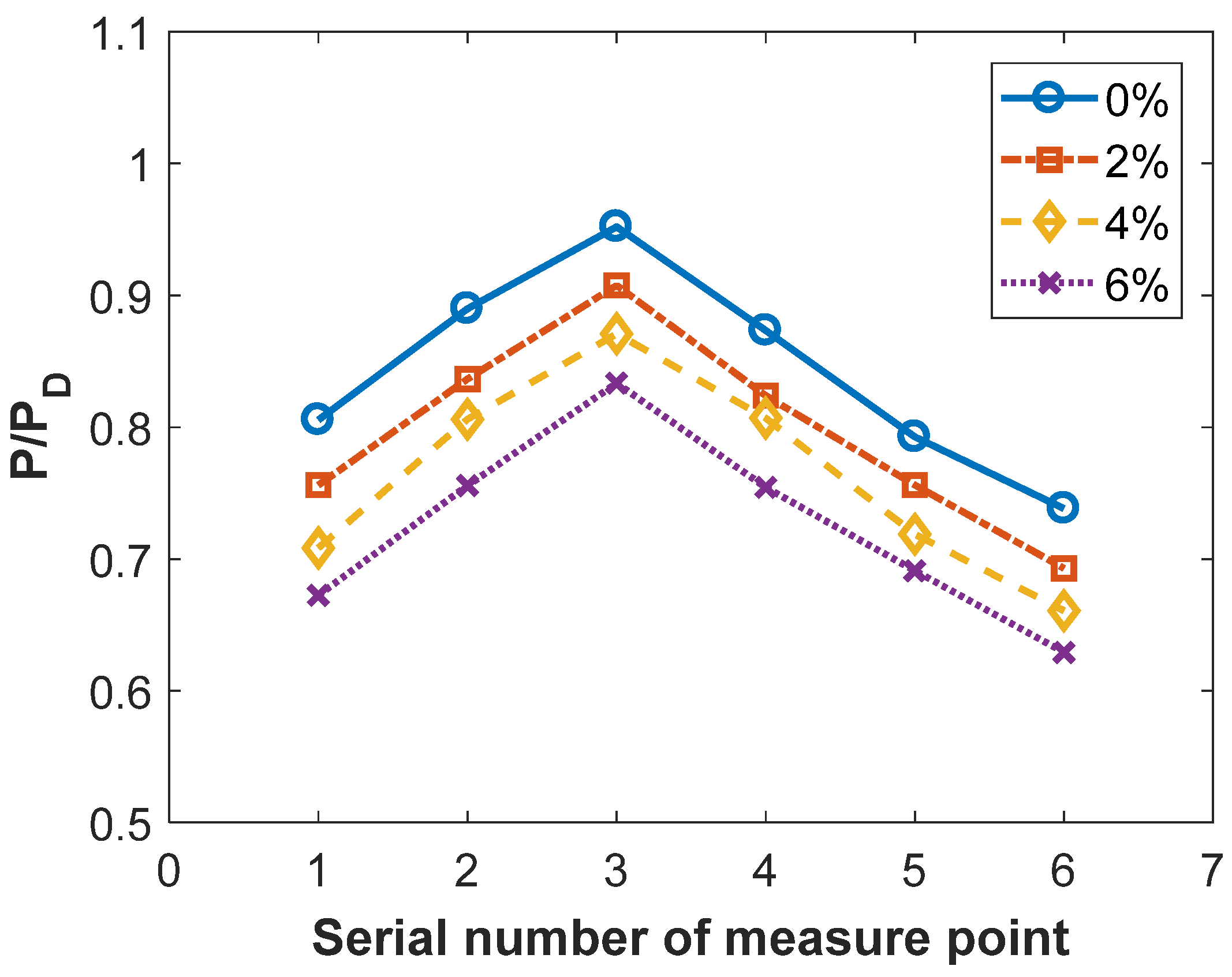
Increasing the pumping volume of the boundary layer within a certain range can further reduce the thickness of the boundary layer and the pressure on the optical cavity, while increasing the chemical reaction platform power. However, excessive pumping volume reduces the power.
(3)
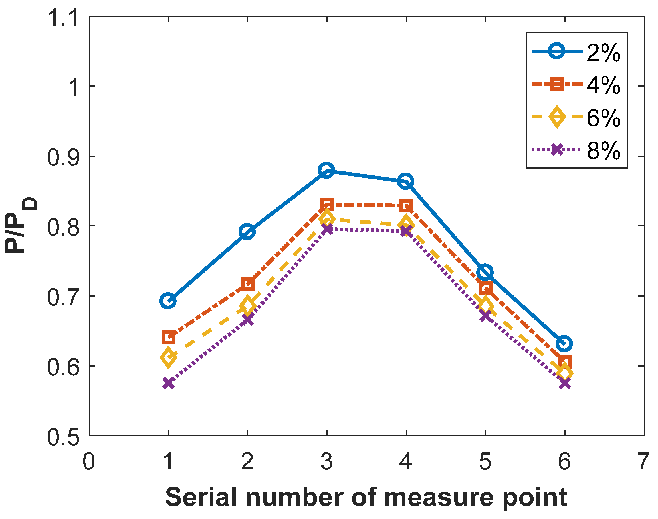
Among the three experimental parameters, the mainstream ejection mode was the most sensitive to pumping volume. When the pumping volume was increased to 6%, the chemical reaction platform power decreased significantly. The orifice plate was not highly sensitive to the pumping volume. When the pumping volume increased from 2% to 8%, the impact on the chemical reaction platform power was apparent.
Subsequently, a supersonic diffuser based on active gas pressurization sprayed high-pressure supersonic active gas in the channel, which can realize efficient pressure recovery and cut off the propagation path of the disturbance by mixing it with the incoming gas. In this study, a supersonic diffuser based on active gas pressurization was studied experimentally, and the following conclusions were drawn:
(1)
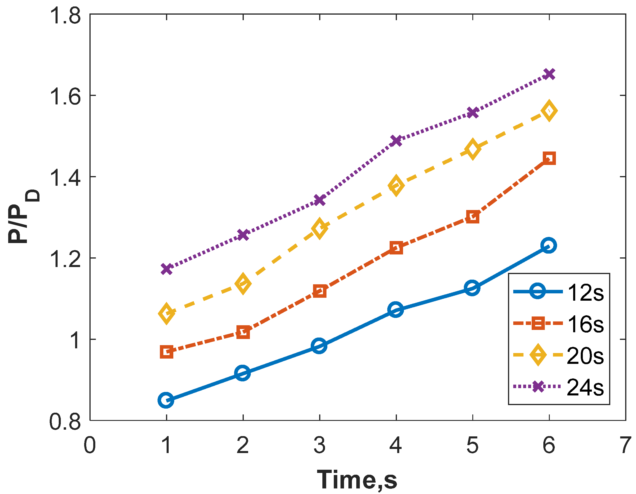
When the supersonic diffuser operates at the design point, it can start smoothly and operate normally under an initial back pressure of 3.85 PD. If the flow rate of the active gas is properly increased, the diffuser performance can be further improved.
(2)
The results of experiment 1# show that the incoming flow of the chemical reaction platform was more sensitive to the blocked area of the downstream channel. If the blocked area is excessively large, the incoming flow of the chemical reaction platform will be blocked, resulting in abnormal operation of the reaction platform.
(3)
The results of experiments 2# and 3# show that the diffuser can be started smoothly at an initial back pressure of approximately 3.9 PD and stabilized the flow field in the optical cavity well, preventing the propagation of downstream disturbance and creating necessary conditions for a normal reaction in the optical cavity.

5. Conclusions

In this study, both the boundary layer suction method and supersonic diffuser ejection were employed for experimental research aimed at exploring the low Re number flow behavior, as well as enhancing an optical cavity of a chemical laser system. Among all the experimental parameters, it was found that the mainstream ejection mode was the most effective boundary layer suction method, allowing for significant control of energy power and pressure within the optical cavity. Regarding the supersonic diffuser, optimal parameters were determined experimentally to enhance the chemical reaction platform’s capacity to withstand high back pressure and airflow disturbances. Overall, this study focused on investigating low Reynolds flow with chemical reactions in the SCRP. The findings presented in this study have the potential for applications in improving the energy output of chemical laser systems.
The variations in pressure in the optical cavity with a solid plate prove that the boundary layer control in the optical cavity is necessary for the efficient work of the SCRP. The comparison between the three cavity structures and test pieces shows that the mainstream ejection slot can significantly regulate the energy power by controlling the pumping volume. The other two methods, the slotted and orifice plate, were effective in controlling the growth of the boundary layer but could not apparently change the power on the cavity, especially when the pumping volume exceeded a certain threshold.
As for the pressure recovery performance of the chemical laser system, an active gas booster supersonic diffuser with a low Re number and internal reaction exothermic flow was studied. The increase in the initial back pressure of the vacuum tank brings difficulty for the diffuser to maintain the pressure in the optical cavity, and an active booster-type supersonic diffuser was installed downstream of the optical cavity to create a low-pressure and stable environment in the optical cavity. An experimental comparison between the three pieces was also investigated, and the energy increase in SCRP docking with the 2# supersonic diffuser is biggest at 32%. All in all, both the boundary layer control method as well as the novel design of the supersonic diffuser could be good choices for the system design of chemical laser systems, which could give improvements in working conditions and energy release and give good support for the further analysis of the aero-optical effect.

Author Contributions

Conceptualization, D.X.; methodology, X.G.; formal analysis, Y.G.; investigation, Z.R. and J.C.; project administration, D.X.; funding acquisition, D.X. All authors have read and agreed to the published version of the manuscript.

Funding

This research was funded by the Equipment Comprehensive Research Project, grant number JK20211A010089.

Institutional Review Board Statement

Not applicable.

Informed Consent Statement

Not applicable.

Data Availability Statement

No new data were created or analyzed in this study. Data sharing is not applicable to this article.

Conflicts of Interest

The authors declare no conflict of interest. The sponsors had no role in the design, execution, interpretation, or writing of the study.

References

  1. Rowley, A.; Stehle, Y.; Kilby, L.; Bashant, C. Graphene oxide membranes: Controlled laser reduction for sensing applications. C 2023, 9, 74. [Google Scholar] [CrossRef]
  2. Cocean, A.; Cocean, I.; Cimpoesu, N.; Cocean, G.; Cimpoesu, R.; Postolachi, C.; Popescu, V.; Gurlui, S. Laser induced method to produce Curcuminoid-Silanol thin films for transdermal patches using irradiation of turmeric target. Appl. Sci. 2021, 11, 4030. [Google Scholar] [CrossRef]
  3. Huai, Y.; Jia, S.Q.; Wu, K.N.; Jin, Y.Q.; Sang, F.T. Numerical investigation of the boundary layer separation in chemical oxygen iodine laser. Opt. Laser Technol. 2017, 96, 276–282. [Google Scholar] [CrossRef]
  4. Sang, F.T.; Jin, Y.Q.; Fang, B.J. Chemical Oxygen-Iodine Lasers; National Defense Industry Press: Beijing, China, 2015. [Google Scholar]
  5. Saavedra, J.; Paniagua, G.; Lavagnoli, S. On the transient response of the turbulent boundary layer inception in compressible flows. J. Fluid Mech. 2018, 850, 1117–1141. [Google Scholar] [CrossRef]
  6. Polivanov, P.; Vishnyakov, O.; Sidorenko, A. Study of Plasma-Based Vortex Generator in Supersonic Turbulent Boundary Layer. Aerospace 2023, 10, 363. [Google Scholar] [CrossRef]
  7. Ramsay, J.; Sellier, M.; Ho, W.H. Effects of boundary layer suction control on flow through an axisymmetric diverging channel. J. R. Soc. New Zealand 2020, 51, 389–408. [Google Scholar] [CrossRef]
  8. Petha, S.; Vignesh, R.; Kim, T.H.; Kim, H.D. Control of the oscillations of shock train using boundary layer suction. Aerosp. Sci. Technol. 2021, 118, 107012. [Google Scholar] [CrossRef]
  9. Kade, S.A.; Tufan, K.G.; Rajan, K. Active Flow Control of a High-Lift Supercritical Airfoil with Microjet Actuators. AIAA J. 2020, 58, 2053–2069. [Google Scholar] [CrossRef]
  10. Pour, R.; Mohammad, J.; Masoumi, Y.; Rezaei, S.; Seyed, M.; Huang, G.P. Controlling flow separation over a curved ramp using vortex generator microjets. Phys. Fluids 2022, 34, 115114. [Google Scholar] [CrossRef]
  11. Reese, B.M.; Collins, J.; Emmanuel, G.; Fernandez, E.; Alvi, F.S. Nonlinear Adaptive Approach to Microjet-Based Flow Separation Control. AIAA J. 2022, 54, 3002–3014. [Google Scholar] [CrossRef]
  12. Gupta, P.; Kumar, P.; Rao, S.M.V. Low-frequency unsteadiness of recompression shock structures in the diffuser of supersonic ejectors. Phys. Fluids 2023, 35, 036119. [Google Scholar] [CrossRef]
  13. Weiss, A.; Olivier, H. Behavior of a shock train under the influence of boundary-layer suction by a normal slot. Exp. Fluids 2012, 52, 273–287. [Google Scholar] [CrossRef]
  14. Kawatsu, K.; Koike, S.; Kumasaka, T.; Masuya, G.; Takita, K. Pseudo-shock wave produced by backpressure in straight and diverging rectangular ducts. In Proceedings of the AIAA/CIRA 13th International Space Planes and Hypersonics Systems and Technologies Conference, AIAA, Capua, Italy, 16–20 May 2005; Volume 3285. [Google Scholar]
  15. Mahapatra, S.; Kumar, S.; Sinhamahapatra, K.P.; Ghosh, S. Large-eddy simulation of shock-turbulence interaction in supersonic diffuser flows. J. Turbul. 2017, 18, 512–538. [Google Scholar] [CrossRef]
  16. Sajben, M.; Bogar, T.J.; Kroutil, J.C. Experimental investigation of terminal shock sensors for mixed-compression inlets. J. Propuls. Power 1992, 8, 168–174. [Google Scholar] [CrossRef]
  17. Ikui, T.; Matsuo, K.; Sasaguchi, K. Modified diffusion model of pseudo-shock waves considering upstream boundary layers. Bull. JSME 1981, 24, 1920–1927. [Google Scholar] [CrossRef]
  18. Hsieh, T.; Bogar, T.J.; Coakley, T.J. Numerical simulation and comparison with experiment for self-excited oscillations in a diffuser flow. AIAA J. 1987, 25, 936–943. [Google Scholar] [CrossRef]
  19. Chen, J.; Ren, Y. Numerical simulations of the shock train in the diffuser of a supersonic wind tunnel. J. Tsinghua Univ. 2007, 47, 264–267. [Google Scholar]
  20. Chen, J.; Ren, Y. Numerical simulation to the pseudo-shock of the supersonic diffuser in the pressure recovery system. Acta Aerodyn. Sin. 2008, 26, 304–309. [Google Scholar]
  21. Lee, H.J.; Lee, B.J.; Kim, S.D.; Jeung, I.-S. Investigation of the pseudo-shock wave in a two-dimensional supersonic inlet. J. Vis. 2010, 13, 25–32. [Google Scholar] [CrossRef]
  22. Fan, X.; Yang, B.; Zhu, T.; Zhong, J. Investigation on design of Φ240mm hypersonic wind tunnel diffuser. Acta Aerodyn. Sin. 2017, 35, 633–639. [Google Scholar]
  23. Cong, C.; Liao, D.; Qiang, P.; Li, H.Z. Numerical simulations and experimental investigations of flow separation control in diffuser of transonic wind tunnel. J. Comput. Mech. 2012, 29, 561–566. [Google Scholar]
  24. Tong, H.; Sun, Q.; Shaowu, Z. Investigation and analyse on the diffuser of hypersonic wind tunnel. J. Exp. Fluid Mech. 2014, 28, 78–81. [Google Scholar]
  25. Huang, Z.; Zhang, G.; Geng, Z.; Chen, J. Performance of line-divergence subsection supersonic diffuser for CRP. High Power Laser Part Beams 2011, 23, 1211–1214. [Google Scholar] [CrossRef]
Figure 1. Diagram of SCRP.
Applsci 13 11335 g001
Figure 2. Diagram of supersonic diffuser.
Applsci 13 11335 g002
Figure 3. Cavity structure and test pieces. (a) is the slotted plate test piece; (b) is the mainstream ejected plated with the upper and lower slotted plates are arranged in equally spaced slots; (c) is the orifice plate with the spacing between any two adjacent orifices was equal.
Applsci 13 11335 g003
Figure 4. Illustration of the supersonic diffuser experimental set.
Applsci 13 11335 g004
Figure 5. Pressure in the optical cavity during SCRP operation without supersonic diffuser.
Applsci 13 11335 g005
Figure 6. Energy power during independent SCRP operation.
Applsci 13 11335 g006
Figure 7. Distribution of cavity pressure during independent SCRP operation.
Applsci 13 11335 g007
Figure 8. Distribution of cavity pressure at varying pumping rates with a slotted plate.
Applsci 13 11335 g008
Figure 9. Distribution of cavity pressure at different states of the mainstream ejected slot.
Applsci 13 11335 g009
Figure 10. Distribution of cavity pressure at different pumping rates with an orifice plate.
Applsci 13 11335 g010
Figure 11. Pressure in the reaction cavity with a mass rate of active gas at the design point.
Applsci 13 11335 g011
Figure 12. Pressure in the reaction cavity with a mass rate of active gas of 1.2 times the design point.
Applsci 13 11335 g012
Figure 13. Variation in pressure in the reaction cavity during operation with supersonic diffuser 1#.
Applsci 13 11335 g013
Figure 14. Variation in energy power during operation with supersonic diffuser 1#.
Applsci 13 11335 g014
Figure 15. Variation in energy power during operation with supersonic diffusers 2# and 3#.
Applsci 13 11335 g015
Figure 16. Variation in pressure in the reaction cavity during operation with supersonic diffuser 2#.
Applsci 13 11335 g016
Figure 17. Variation in pressure in the reaction cavity during operation with supersonic diffuser 3#.
Applsci 13 11335 g017
Figure 18. Pressure distribution of the reaction cavity and supersonic diffusers.
Applsci 13 11335 g018
Table 1. Parameters of the exhaust gas.
ParameterValueUnit
Ma2.0
T0500K
γ1.586
R708J/(kg·K)
Table 2. Parameters of the active gas flow.
ParameterValueUnit
Ma4.5
T0300K
γ1.4
R287J/(kg·K)
Table 3. Energy power at varying pumping rates with a slotted plate.
Pumping RateN/ND
2%0.695
4%0.698
6%0.682
8%0.664
Table 4. Energy power at different states of the mainstream ejected slot.
ConditionN/ND
mainstream ejection + 0% pumping0.688
mainstream ejection + 2% pumping0.694
mainstream ejection + 4% pumping0.689
mainstream ejection + 6% pumping0.603
Table 5. Energy power at different pumping rates with an orifice plate.
Pumping RateN/ND
2%0.637
4%0.631
6%0.642
8%0.635
Disclaimer/Publisher’s Note: The statements, opinions and data contained in all publications are solely those of the individual author(s) and contributor(s) and not of MDPI and/or the editor(s). MDPI and/or the editor(s) disclaim responsibility for any injury to people or property resulting from any ideas, methods, instructions or products referred to in the content.

