Article

Cement Stabilization of Waste from Contaminated Soils in Terms of Its Installation into Engineered Landfill

by
Sławomir Kwiecień
1,
Alicja Podgórska
2,
Jarosław Rybak
2,*,
Martin Štefánik
3 and
Vlastimil Cheben
3
1
Department of Geotechnics and Roads, Faculty of Civil Engineering, Silesian University of Technology, ul. Akademicka 5, 44-100 Gliwice, Poland
2
Faculty of Civil Engineering, Wroclaw University of Science and Technology, Wyb. Wyspiańskiego 27, 50-370 Wrocław, Poland
3
GEART, s.r.o, P.O. Hviezdoslava 42A, 010 01 Žilina, Slovakia
*
Author to whom correspondence should be addressed.
Appl. Sci. 2023, 13(20), 11485; https://doi.org/10.3390/app132011485
Submission received: 1 September 2023 / Revised: 16 October 2023 / Accepted: 18 October 2023 / Published: 19 October 2023
(This article belongs to the Section Environmental Sciences)

Abstract

:
Remediation and preparation for development is a crucial aspect of the valorization of post-mining areas. This study is focused on technologies devoted to the cement stabilization of post-industrial waste and petroleum contaminated soils. Two case studies are presented. Case 1 is based on the stabilization works of waste from a closed chemical plant in order to turn it into an engineered landfill. The results form the basis for numerical studies of slope stability. The shorter case 2 is based on the laboratory testing of a soil–cement composite with regard to petroleum contamination and the application of active carbon to neutralize it in the course of deep soil mixing. Both cases, due to the use of slag cement, are not considered to be sustainable (due to a relatively high carbon footprint), but they represent current geotechnical practice and form a reference for a wide range of applications. Both cases show the positive impact of stabilization by means of the addition of a hydraulic binder. The effect of soil improvement is measurable in terms of the stability factor of landfill slopes. The effect of active charcoal addition seems to be a valuable improvement to standard deep soil mixing technology in the case of contaminated soil. The presented results, despite their local importance related to the cases under scrutiny, have an important educational and scientific value for the energy sector, where contaminated sites need to be valorized.

1. Introduction

Mining and industrial production generates waste that needs to be stored [1,2,3] or preferably reused with regard to sustainable development [4,5,6]. Mining and industrial waste can differ greatly in its reusability, depending on its type (e.g., coal-associated shale, ash, and slag for building embankments, steel for re-smelting and petroleum contaminated soils) or its adverse impact on the environment (waste from nuclear power plants or chemical plants). For the latter, its disposal most commonly involves sealing it in special containment sites (sarcophagi) that protect the environment from the waste’s harmful effects [7]. Such sites can be located underground [7] or aboveground [8,9]. The crucial issue concerning aboveground storage facilities is the protection of groundwaters [10,11,12].
It must be underlined that methods of soil/tailing stabilization are subject to current development and valuable contributions concerning both sources of contamination and protective measures are being published worldwide [13,14,15,16,17,18,19,20,21].
This study is focused on just one region and two similar sources of soil contamination. Basic information about the sites under study may be found in publications [22,23,24]. A short historical note is given below.
During the decommissioning of a chemical plant in Poland, it was necessary to seal the post-production waste in an aboveground engineered landfill. The sites under consideration, including their technical facilities, were located in the central part of southern Poland, in Upper Silesia. The location has a very rich history. In 1842–1892, an iron foundry was operated there, followed by a factory producing cellulose and paper, from 1919. After World War I, the production of inorganic compounds began in 1922. The chemical plant operated until 1995, when the company’s liquidation began. The production processes involved the application of poisonous substances [22], e.g., nitric, phosphoric, sulfuric, hydrochloric and oxalic acid, barite, soda lye, etc. These were used to produce, for example, barium compounds (sulfide, hydroxide, peroxide, chloride, sulfate, nitrate and carbonate), 30% and 60% lithopone (ZnS, BaSO4), boric acid, borax, strontium salts (carbonate, chromate and sulfate), strontium reagents, sodium sulfide, copper sulfate and zinc phosphate [22]. The operation of all of the plants and wastewater treatment generated waste that was gathered in the direct vicinity of the plant in a disorderly manner, without proper safety measures (see Figure 1). Over several decades of operation, 10 storage sites were established, where 360,000 tons of waste were placed [9]. This led to the contamination of soil, groundwater (both near the surface and that located deeper underground), forming a reservoir of potable water [23], and the Stoła river, which flowed across the storage site. The soil and waters were penetrated mainly by such substances as barium, boron, cadmium, strontium, arsenic and zinc. Tests and chemical analyses confirmed the high concentration of heavy metals in the waters and the soil alike [24,25].

2. Basic Information on the Presented Case Studies

The remediation and valorization of post-production and storage plants must always be preceded by an insight analysis of the contamination and protective measures to diminish its future impact. The case studies presented below were chosen to show different examples from the chosen industrial region (Silesia in Poland). Different technologies have successfully been used to strengthen the contaminated soil and to reduce the spread of contamination.

2.1. Storage Facility (Landfill) of the Chemical Plant

During several decades of operation of a chemical plant in Poland, approximately 360 thousand tons of waste were deposited in 10 landfills in its immediate vicinity. The waste was stored without any protection, which caused the penetration of hazardous substances into the soil and groundwater. After the chemical plant was closed, a decision was made to neutralize the waste by dismantling it and then installing it into an engineered landfill. In the case of one of the designed landfills, there was a need to improve a very soft waste (over 72,000 m3) in order to increase its shear strength. For this purpose, slag cement stabilization was used. For design reasons, it became necessary to determine the shear strength and unit weight of the waste stabilized with 10% cement and its influence on the stability of the landfill. The strength parameters were obtained via direct shear tests and showed that the cement-stabilized waste is characterized by an angle of shear resistance equal to 32°, cohesion equal to 25.9 kPa and a volumetric weight of 14.6 kN/m3 [25]. Stability analysis was carried out using FEM analysis and the strength reduction method and showed that the stabilization of chemical waste with cement made it possible to deposit it safely in the engineered landfill [26,27,28,29,30,31].
The comprehensive decommissioning of the chemical plant involved, for example, demolishing the facilities and all installations, constructing an engineered landfill, including associated infrastructure, the removal of the existing waste storage areas, the treatment of contaminated groundwater, upgrading and operating the existing water treatment plant, and regulating the Stoła river, including the revitalization of its glacial valley. The total amount of waste gathered at the plant, including the contaminated soil from underneath the dumping grounds, the contaminated soil from the plant grounds, the hazardous waste generated during the demolition and removal of processing installations, was estimated at about 1.5 million m3 [32]. During the removal of waste storage area No. 5, after its dismantling but before its transfer to a properly secured engineered landfill, the waste was chemically stabilized at solidification points by mixing with a 10% slag cement (CEM II/B-S-32.5 R) addition, in order to improve its mechanical properties, particularly its strength. The waste was mostly like a very soft cohesive soil (Figure 2), and because it was stored in the form of tall embankments (up to 17 m), it was likely that it had lost its stability due to the formation of sliding surfaces crossing the waste embankment, as the waste was characterized by a near-zero shear strength.
As it is known, the stability of soil-made structures depends mainly on their strength and physical parameters, thus the need to strengthen the waste and to determine the angle of shearing resistance (ϕ) and its cohesion (c) and unit weight (γ) values. In 2010–2011, at the Geotechnics and Roads Department of the Silesian University of Technology, a study was conducted to determine the above strength and physical parameters of waste stabilized chemically with slag cement (CEM II/B-S-32.5 R) added at a 1:10 weight ratio, for the purpose of neutralizing about 72,000 m3 of chemical waste.

2.2. Remediation Works in a Former Coking Plant Concerning Pollution with Petroleum Compounds

The soil used for the research comes from the area of a former coking plant, which is currently undergoing the process of remediation and reclamation. It is an area of approx. 5 ha, which has been polluted mainly with petroleum compounds, but also cyanides, heavy metals and metalloids (including arsenic, barium, zinc, cobalt, copper, nickel and lead). The remediation project assumes ex situ treatment, using bioremediation, phytoremediation, as well as the incorporation of reactive barriers. As a result of the entire implementation, a green recreational space is to be created in the area of the coking plant, with small architectural objects and an educational path covering the secured and restored remains of the plant, which operated at the beginning of the 20th century.
Due to poor geotechnical conditions, the foundations of the new facilities were based on soil improved by means of deep soil mixing (DSM) using a hydraulic binder (cement) with additives chosen to reduce the negative impact of contamination. The initial amount of C6–C12 hydrocarbons (gasoline fraction) exceeded by 38 times the acceptable content, equal to 1 mg/kg. The soil was mixed with CEM I 42.5R cement grout with a density of 1.7 kg/dm3 and a corresponding water/cement ration equal to W/C = 1.4. The applied amount of cement provided approx. 240 kg of cement for a resulting 1 m3 of the composite. As the average weight of the cubic sample was 6.48 kg and its density was 1920 kg/m3, this means that the amount of cement in the composite reached almost 12.5%.
Activated carbon (charcoal) was added to half of the sample series. Activated carbon is a highly porous substance with a highly developed specific surface, which is responsible for its remarkable ability to adsorb chemical compounds from gases and liquids. It is made of wood, hard coal, lignite, peat and other materials. It takes the form of fibers, non-woven fabrics, spheres or a dusty or granular form. It is used, among other things, for the purification of industrial waters, sewage and drinking water from oil-derivative pollutants. In this study, 1.5% of the total weight of the mixture was used.

3. Materials and Methods

3.1. Engineered Landfill Concept

The engineered landfill, with a total area of about 16.5 ha, is located at the chemical plant site. It will be placed at the location of a previous waste storage area and on the grounds of the demolished industrial facilities [25]. The engineered landfill is designed as an aboveground facility, divided into 5 areas. The areas will form a single body with a height up to 17 m above ground level. The site’s bottom foundation is designed to be below artificial fills (made grounds) and the waste, and its thickness will be about 1 m, and the foundation will be located at least 1 m above the groundwater level. The whole site will be surrounded by an external embankment (dike) 2.1 to 4 m high and with a 5 m crest width. The external slopes are characterized by a 1:2 inclination, internals are at a 1:3 inclination [25]. The external and middle slope sections are built of soil from excavations. The internal slopes, which separate individual quarters, are made of clay used for sealing the engineered landfill base. At the bottom of the site, there will be a mineral sealing layer made of clay, inclined to at least 1% to enable effective draining using a drainage layer placed on the sealing layer [25]. The waste discussed herein was intended for area No. 5.

3.2. Soil and Water Conditions of Engineered Landfill

In terms of geology, the soil is made up of Quaternary formations lying on Triassic and Jurassic layers, with underlying Carboniferous formations [25]. The Carboniferous formations are represented by shale, sandstones, conglomerates, and coal. The Triassic deposits are represented by Bunter sandstone and Muschelkalk, while the Jurassic deposits, by clay formations with gravel and conglomerate beds. Their total thickness reaches 200–300 m. The Quaternary deposits are layers of fluvioglacial sands and gravels separated by beds of clay, with thicknesses of up to several meters. Groundwater was found in the Quaternary and Triassic deposits. The Quaternary stage includes sandy water-bearing layers separated by clay layers and is fed mainly by precipitation. The Triassic hydrological stage contains fractured and porous waters in limestone and dolomite layers of Muschelkalk, fed by permeation from the Quaternary aquifer. Due to the high rigidity and strength of the rock layers, only the Quaternary soil layers were considered when modelling the stability problem. For area No. 5, these were layers of medium-dense medium sand with a thickness of up to several meters.

3.3. Cement Stabilisation of Engineered Landfill

To improve the surface soil layers, particularly when constructing embankment layers, mechanical and/or chemical stabilization is used. The latter includes stabilization with cement [21]. This type of stabilization has been in use in geotechnical engineering for almost a hundred years. Stabilization using this method involves properly fragmenting the layer to be stabilized, adding a suitable amount of cement, mixing it into a uniform phase, laying it in place, thickening and properly curing. For soils, there are clear guidelines concerning the use of cement for specific soil types. Soils subjected to such stabilization must meet specific requirements, for example those of standard PN-S-96012:1997 [21], which concerns their grain size, plasticity index (Ip = 15%), liquid limit (wL = 40%), organic content (Iom = 2%), reaction (5 < pH < 8) and sulfate content (SO3 = 1%). The cement–soil load-bearing backbone forms as a result of the cement binding with the distributed sand and silt fraction. Soil particles not bound to cement form the filler and binder of the load-bearing backbone and, at the same time, serve as a dampener of external forces. When stabilizing soils, the amount of cement added is usually 3 to 10% (by weight) [21]. Of course, there are no such guidelines for using this type of stabilization with chemical plant waste. Before commencing the research, macroscopic waste mixing tests at different slag cement (CEM II/B-S-32.5 R) levels were conducted. They demonstrated that properties are significantly improved (very soft consistency turned into very stiff consistency) when about 10% slag cement (by weight) is added. Further laboratory tests to determine the angle of shearing resistance (ϕ) and cohesion (c) were to demonstrate whether it was suitable for use in incorporation into an engineered landfill. The measure of this suitability will be obtaining an appropriate stability level (stability factor SF ≥ 1.5) for the waste engineered landfill, determined on the basis of numeric calculations using the finite element method.
When constructing the designed storage site, the waste was mixed at the solidification points with a capacity of 50 t/h, placed at the chemical plant grounds. The points were made up of cement silos and double-shaft continuous mixers with a feed functionality. First, the waste will be retrieved by excavators from the storage location, transported to the solidification points, processed, and subsequently transported by trucks and placed at the storage site.
The strength parameters were determined by the tests conducted in a shearbox apparatus as per PN-B-04481:1988 [26]. In this test, the shearing strength is determined by applying a shearing force in a direction perpendicular to two opposite sides of a sample with a square cross-section (in projection), following the application of a force normal to the shearing plane. The shearing strength is considered to be the instantaneous strength achieved at a constant deformation speed within a range of up to 10%. The tests were performed on 60 × 60 × 18 mm cuboid samples cut from the blocks with the diameter of 200 mm and the height of 250 mm. The shearing plane was located at half sample height. Frame displacement in the horizontal and vertical directions was measured using dial gauges operating at the accuracy of 0.01 mm. The box was moved mechanically at a constant rate of 0.05 mm/min. The shearing force and the force normal to the shearing plane were measured at an accuracy of 1 kPa. The upper and lower surfaces of the sample were fitted with support plates with ribs and a right-angled triangular cross-section, positioned so that the hypotenuse surface of the rib was facing in the same direction as the shearing force when the frame moved in the direction in which the force was applied, and in the opposite direction when the frame was immobile. A plate transferring the normal load was placed on the upper support plate.
Five samples sheared at different normal stress values of 50 kPa, 100 kPa, 150 kPa, 200 kPa and 250 kPa were used for every determination of angle of shearing resistance and cohesion. The angle of shearing resistance and cohesion values was calculated using the least squares method for the following Equation (1):
τ f = σ t g ϕ + c
Measurements of displacement and applied forces were taken at 30 s intervals. The tests were performed until the shear force value remained constant or dropped by no more than 10% within the deformation range in three consecutive readings. Otherwise, the shearing continued until a relative deformation of 10% was reached. Sample shear strength was calculated using the following Equation (2):
τ f = Q m a x a ( a r )

3.4. Testing of Petroleum Contaminated Soil Mixed with Cement, Optionally with Addition of 1.5% of Carbon Powder

The application of active carbon was intended to react with C6–C12 hydrocarbons (gasoline fraction) before the cement starts to bind the composite. Active carbon was just an additive, but what is crucial is that it was added simultaneously with the binding agent (cement). This is very important concerning field applications where the single-stage mixing process is more economically attractive, compared to separate phases of mixing with active carbon (remediation phase) and cement (strengthening phase). In laboratory conditions, the processing of contaminated soil is carried out in a more efficient way (in stages); however, the main goal was to test the work conducted as it will be applied in the real-world conditions.
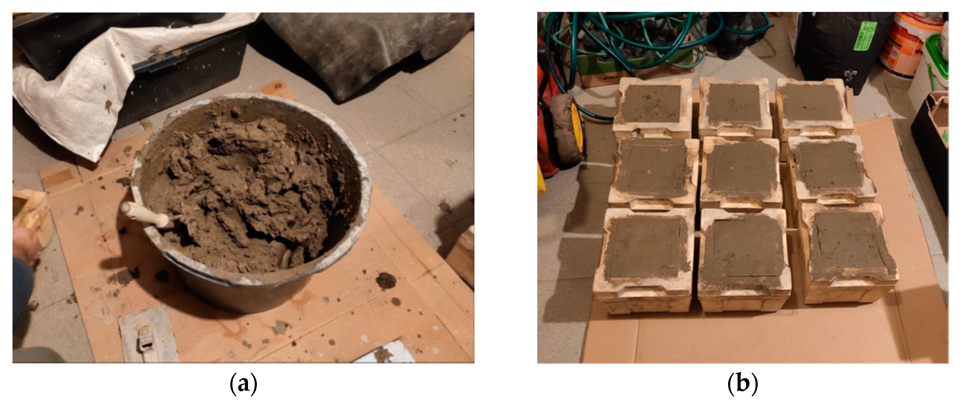
Each batch of soil brought to the laboratory was mixed for homogenization. All ingredients were weighed in the correct proportions. First, a cement slurry was made, which was then added to the soil and thoroughly mixed (see Figure 3a) using a drill with a mixer.
Samples in the shape of cubes with a side of 15 cm were formed from the mixture and covered for maturation, which took place at a constant temperature and humidity, close to natural conditions (see Figure 3b).
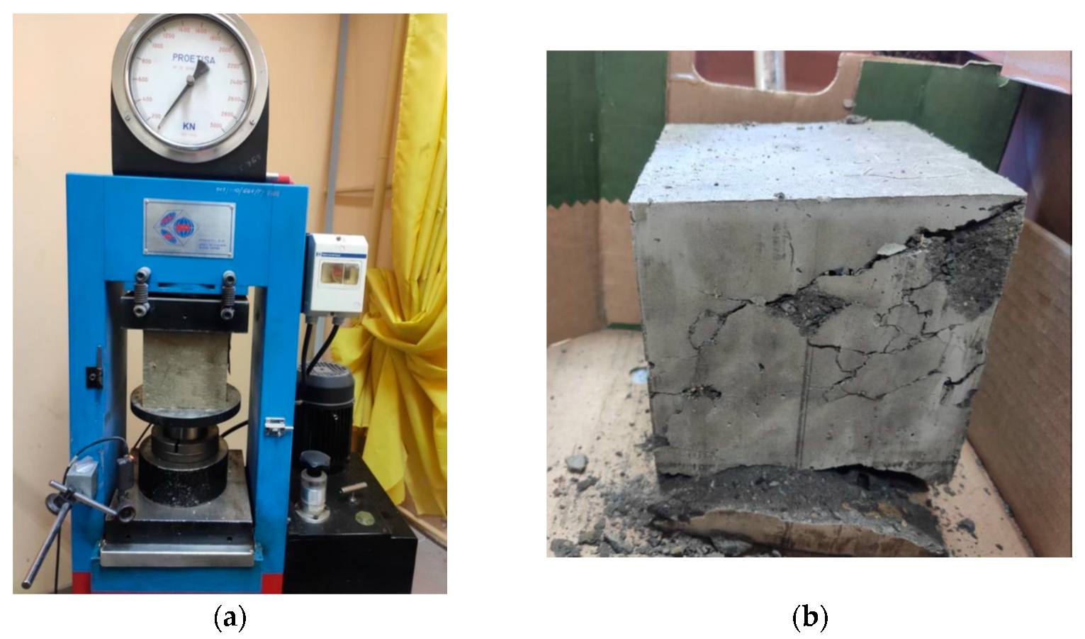
The uniaxial compressive strength test was carried out after 7 days and 28 days of curing, using a strength press connected to a measuring apparatus (see Figure 4a) recording the applied force with the accompanying displacement, which allowed the stress path to be recorded.
All samples were weighed before the test. Uniaxial compressive strength and elastic modulus were derived from recorded data. The test was static with a constant displacement rate and constant temperature and humidity conditions. A typical mode destruction is given in Figure 4b.
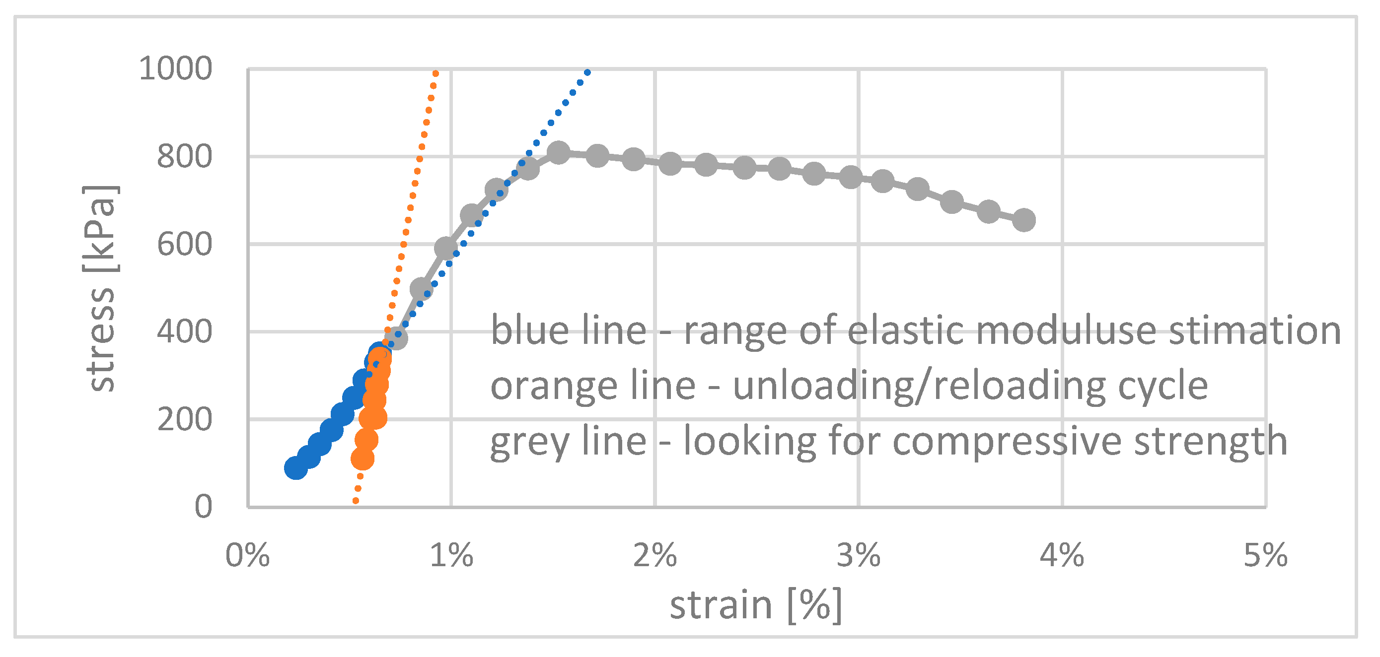
When a test is performed in laboratory conditions, it makes it possible to control several unloading/reloading cycles. Elastic modulus may be derived from the stress–strain curve. In the test, two procedures were applied, depending on the number of unloading/reloading cycles. If the sample was unloaded/reloaded only once, the cycle was scheduled at 50% of expected compressive strength. One may observe a very significant increase in the material stiffness in the first unloading/reloading cycle and a further increase in the second cycle in Figure 5.
The testing with unloading/reloading cycles took place on the 28th day of the curing time of the cubic samples under scrutiny. The results of the performed tests are given in the next section, with special regard to the influence of the active charcoal (carbon) addition.

4. Results of Tests of Physical and Strength Parameters of Slag Cement-Stabilized Waste and Contaminated Soil

4.1. Results of Stabilized Waste Testing

A total of 87 waste samples were taken from random locations at site No. 5 (1 sample per approx. 8300 m3 of waste). After the stabilization and the mixing with a 10% slag cement (CEM II/B-S-32.5 R) addition, the samples were stored for 14 days under natural conditions. This was to simulate conditions similar to those following the internment at the engineered landfill, without application of any curing treatment.
Knowing the σ - τ f relation made it possible to plot an approximation line (Figure 6). If the deviation of any point from this line exceeded 25% of the τ f value, such points were discarded, and the test was repeated. In total, 435 shearings were conducted.
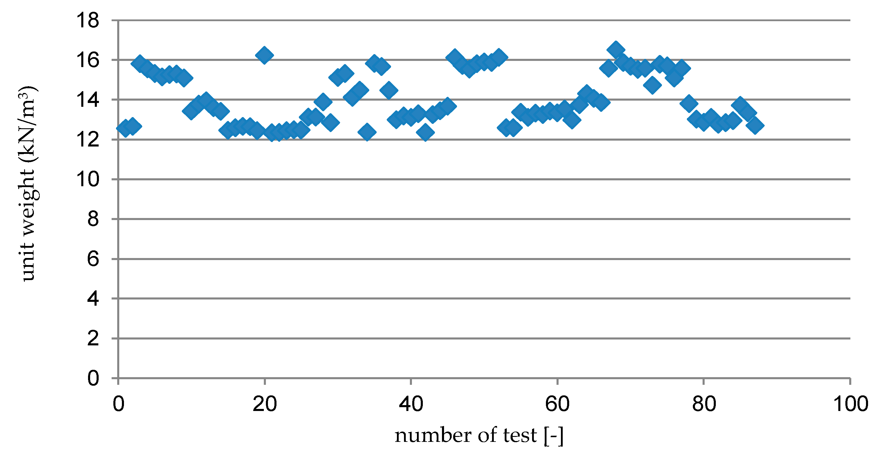
Physical parameters of the waste were also determined during the tests. Before each shearing and immediately following the test, its moisture content was determined. The unit weight of the stabilized waste was determined based on samples used for the shearing tests. The samples were weighed, measured (sample side and height dimensions), and the unit weight was calculated as follows (Equation (3)):
γ = m V g
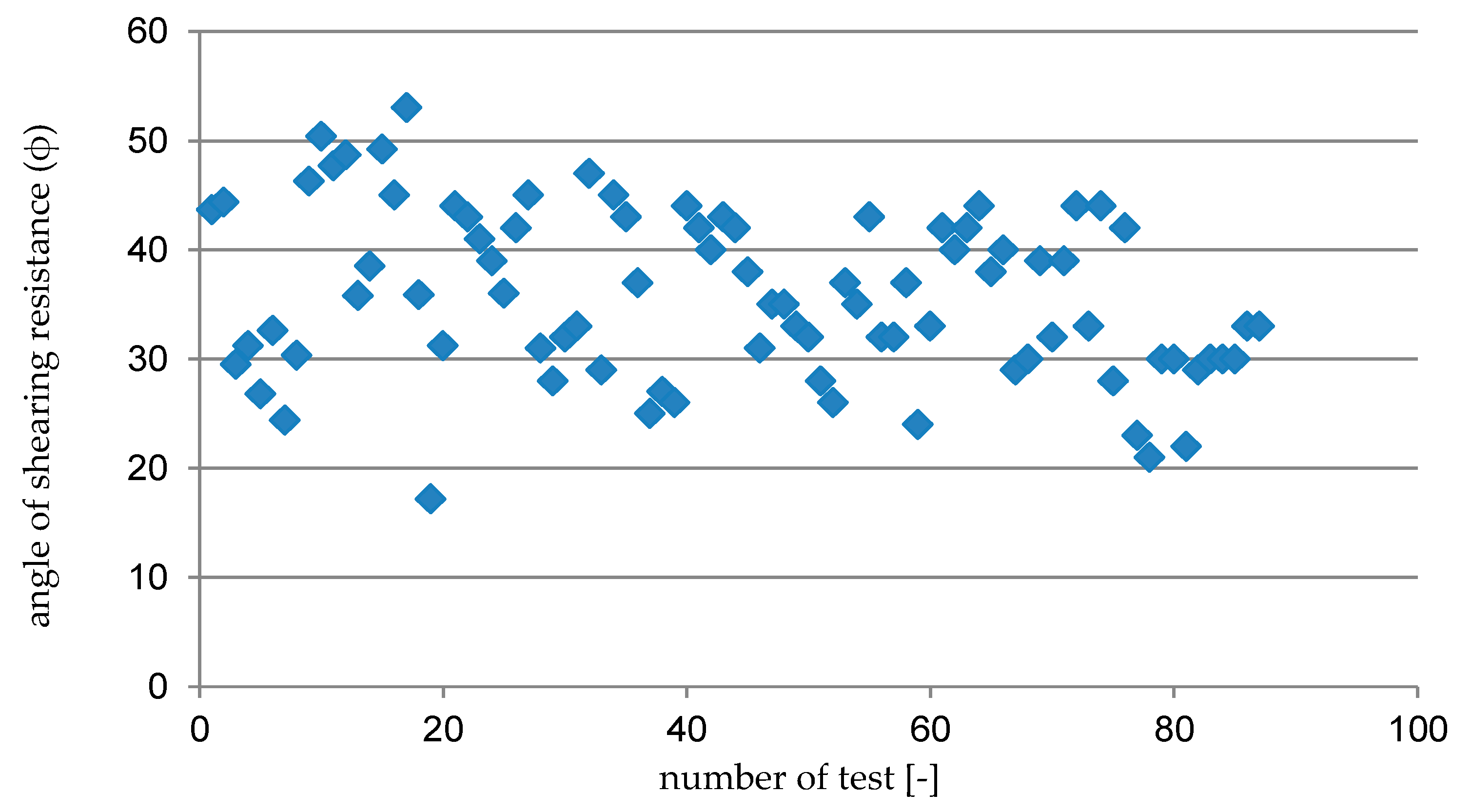
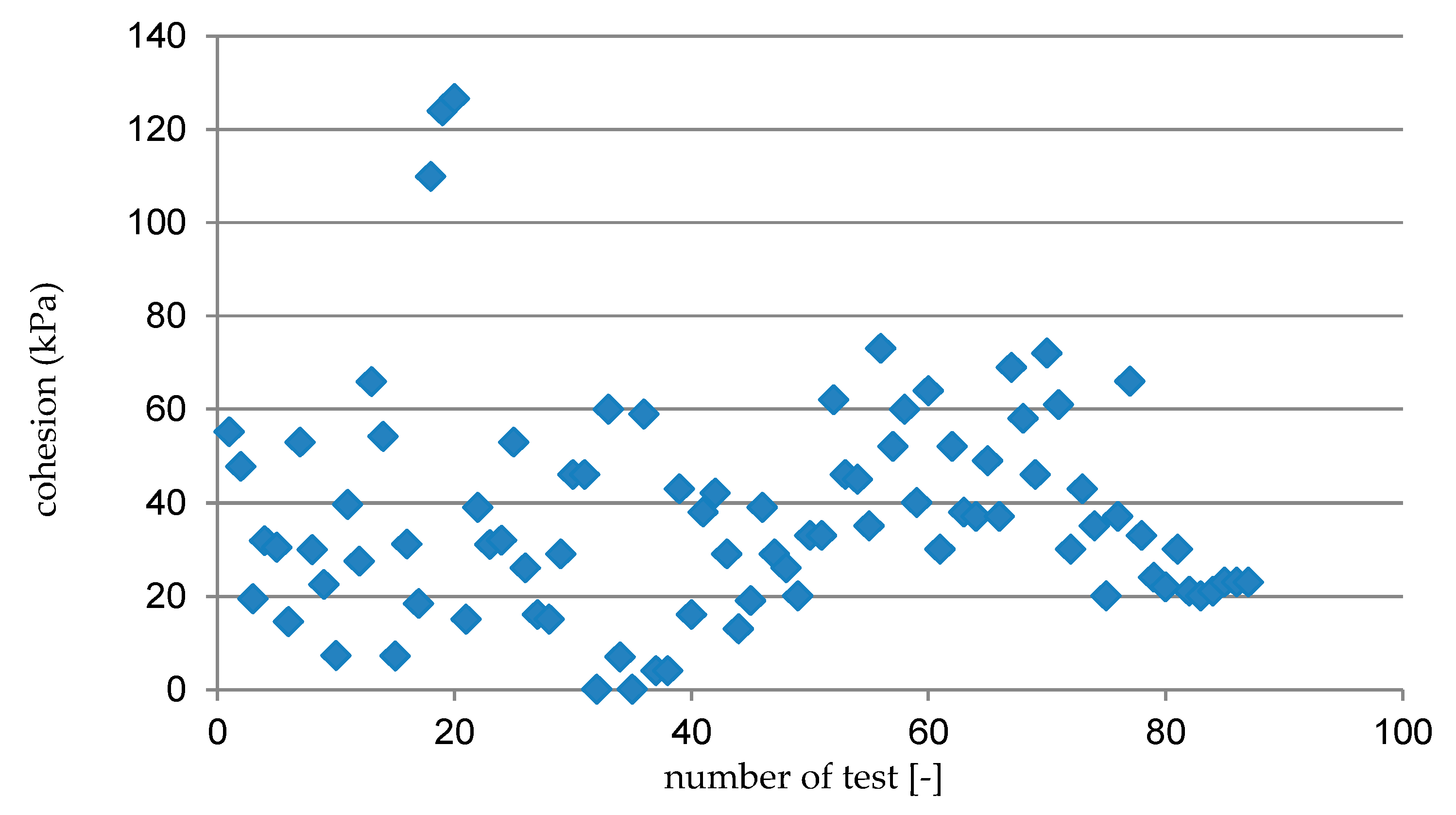
A summary of the unit weights obtained for all of the samples is shown in Figure 7. The approximation line inclination angle in the σ - τ f system (Figure 6) was equal to the angle of shearing resistance (ϕ) of the test waste, and cohesion was determined on the basis of the value of the line crossing with the shear strength axis τ f . The summary of the results is shown in Figure 8 and Figure 9.
The arithmetic mean and sample standard deviation were calculated for all of the parameters determined in the tests, while the characteristic value (Table 1) was determined based on Equation (4):
x k = x ( n ) ± 0.5 s
The characteristic values of the angle of shearing resistance (ϕ), cohesion (c) and unit weight (γ) of the cement-stabilized waste served as the basis for calculating the stability of the planned waste engineered landfill are given below in Table 1.

4.2. Results Obtained for a Petroleum Contaminated Soil–Cement Composite

The efficiency of soil improvement by means of deep soil mixing with hydraulic binder (cement) is inevitable. The interesting part of the research was the possible increase in mechanical parameters of the composite caused by the additional application of active carbon. Table 2 presents the results obtained after 7 and 28 days of curing.
According to the data juxtaposed in Table 2, the application of 1.5% of active carbon was beneficial for both uniaxial compressive strength and elastic modulus. As expected in most of the cases, a significant increase in mechanical properties in time may be observed (with only one exception). The measured values of strength and stiffness were in every case more favorable for the composite with the addition of active carbon. The increase in mechanical properties reached 7–14% when active carbon was applied. That looks very promising, concerning the practical outcomes.

5. Calculations of Stability for the Planned Engineered Landfill

5.1. Model and Calculation Assumptions Based on Case 1 Results (Chemical Plant)

The goal of the numerical studies was just to prove that the modified parameters of the resulting soil–cement composite guarantee safe conduct of the earthworks and further stability of the earth structure. That was not evident and all laboratory works had to be conducted prior to the extensive and expensive field operations. The numerical model is not very sophisticated; however, it is a cautious estimate of the real situation.
The stability of the “engineered landfill–ground” system was analyzed using the finite element method, and calculations were made using the Z_Soil 2011 software [28,29]. The calculations were made in a plain strain state. Due to the layered structure of the site, as per Section 2, a cross-section through the waste storage location was selected.
The calculation analysis was divided into the following stages. First, a primary stress condition was generated in the ground. Secondly, the construction of subsequent layers of artificial fills was simulated. The next stage was to assume a load on the site crest to simulate the operation of heavy equipment (excavators, transport vehicles) in the form of an evenly spread load with a value of 10 kPa (Figure 10). The final stage of the calculations, which is key to this discussion, was stability analysis.
An elastic–perfectly plastic material model with a Mohr–Coulomb plasticity surface and non-associated flow rule was assumed for the soil system. The system’s behavior within the elastic work range is described by two parameters: elastic (Young’s) modulus (E) and Poisson’s ratio (ν), while the plastic surface position depends on cohesion (c) and angle of shearing resistance (ϕ). The benefit of using this model is the ability to identify its parameters based on standard tests, e.g., in a direct shearing test.
The soil base and waste parameters were assumed on the basis of the geotechnical documentation, construction design, and the author’s own research (Table 3). Standard geotechnical boundary conditions were applied—horizontal and vertical displacements were blocked at the bottom edge of the system, while horizontal displacements were blocked at the lateral vertical edges.
The reduction in cohesion (c) and angle of shearing resistance tangent (tgϕ) method was used to calculate the safety factor using the numerical method [30]. For the two-parameter models used in the analysis in question, five stages can be identified in the stability calculation algorithm [28]:
-
Assumption of a safety factor (SFn) equal to an initial value defined by the user (SF0)—most commonly a boundary problem of the system equilibrium state is solved, an initial stress distribution is determined in the analyzed object (“in situ” state), caused, for example, by its own state or other constant static loads. In this case, meeting the conditions of elastic–plastic equilibrium corresponds to achieving the safety factor SF = 1.0;
-
For each calculation step, assuming SFn+1= SFn + ΔSF (step ΔSF in the described models was defined at 0.01), while at the same time calculating cn+1 = c/SFn+1 and tgϕn+1 = tgϕn/SFn+1. By step-wise reduction in cohesion c and angle of shearing resistance tangent ϕ, a less stable system is obtained with each calculation step;
-
Solving the problem using software, with the necessary iterations;
-
Performing system stability calculations for the assumed sequence of safety factors, until solution divergence is achieved in two consecutive steps—if an iterative process divergence occurs (manifesting in the occurrence of very large deformations, often with a qualitatively different form than those in the equilibrium state), it means that with the currently assumed safety factor, the structure is not stable;
-
Determination of the safety factor when solution divergence is obtained SFn ≤ SF ≤ SFn+1—the last value of the SF-reducing coefficient at which an equilibrium state can still be achieved is assumed as the safety factor value.

5.2. Calculation Results

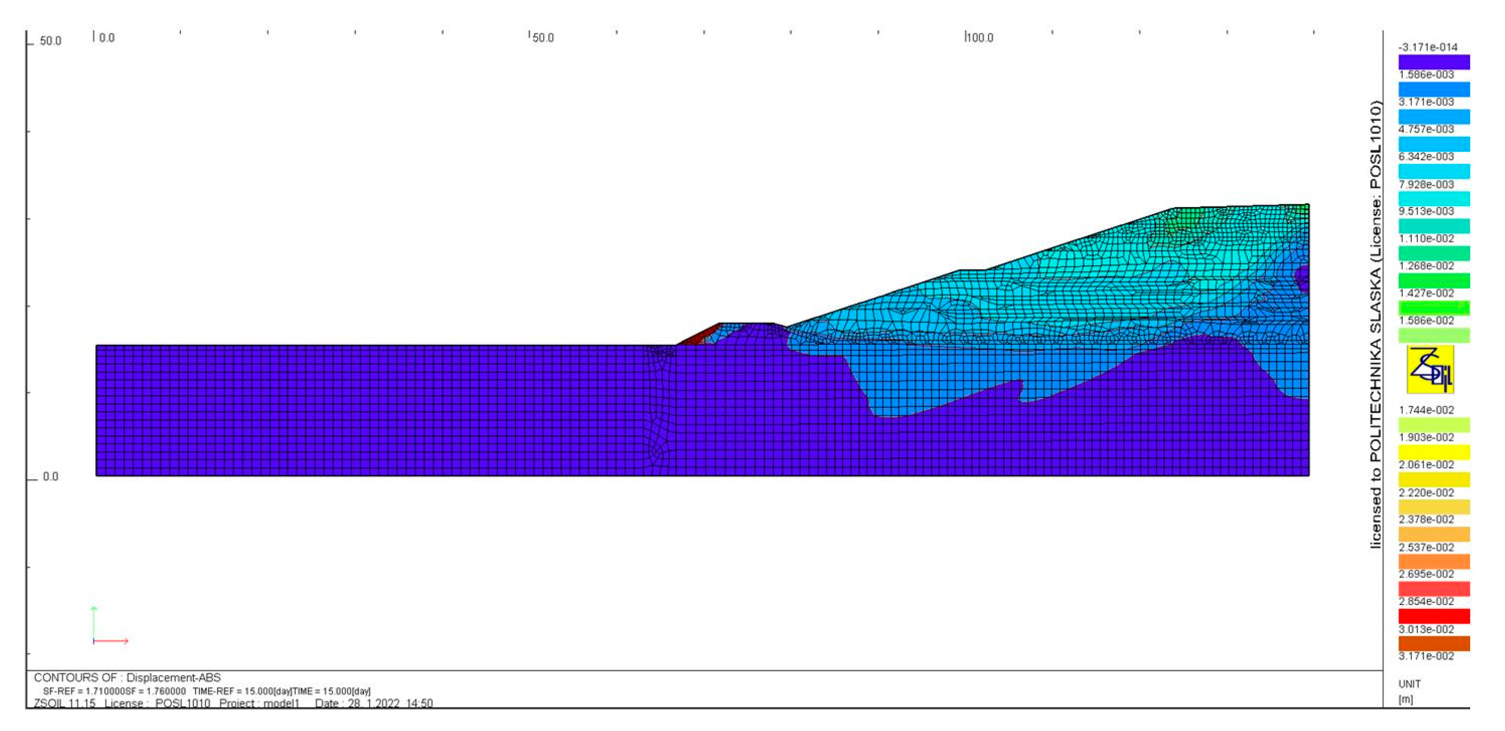
The calculation analysis demonstrated that the planned engineered landfill, where the slag cement-stabilized waste would be placed, would be characterized by a safety factor of 1.71. The map of absolute displacements when stability is lost is shown in Figure 11. The analysis of Figure 11 indicates that a local loss of stability occurs in the external slope of the embankment surrounding the engineered landfill. The formation of a global sliding plane in the central part of the storage site also begins to be visible. When using a material with a greater grain size than sand and a greater index of density (ID > 50%), characterized by strength parameters of ϕ = 40°, c = 1 kPa, the safety factor increases to SF = 1.91, the character of engineered landfill damage also changes (Figure 12)—a global loss of stability occurs, and the shear plane crosses the waste in the landfill.
Both in the first and the second case, the safety factor value achieved is sufficient. For such structures, it is necessary to achieve a stability coefficient of about SF = 1.5. The occurrence of a landslide if the SF > 1.5 condition is met is highly unlikely [33].

6. Discussion

When constructing embankments made of soils that, as a result of mechanical compacting, are characterized by an inadequate strength and/or stiffness, it is possible to improve them by using chemical stabilization by means of various binders. The most popular stabilizing agents available include cement and various additions (fly ash, bottom ash, etc.). The procedure of strengthening with the use of this method includes: properly fragmenting the layer to be stabilized, adding a suitable amount of cement, mixing it into a uniform phase, laying it in place for thickening and properly curing.
The use of cement can also be helpful when stabilizing other materials, such as waste, as was the case for one chemical plant in southern Poland. During the removal of a storage area for hazardous waste produced during the operation of the chemical plant, it was necessary to construct a new, properly secured storage site— an engineered landfill. The existing waste, similar to a very soft cohesive soil, was to be interred in suitable quarters at a storage site with a height of up to 17 m. Due to the near-zero shear strength, it was necessary to strengthen the waste using cement stabilization to improve its strength parameters. These ideas (using slag cement) are not considered to be sustainable due to their relatively high carbon footprint, but cement stabilization is widely used due to the process’s simplicity and a relatively high level of confidence. Initial macroscopic tests indicated that a 10% slag cement (CEM II/B-S-32.5 R) addition changes its state from very soft consistency to very stiff consistency. However, it was necessary to determine the physical and strength parameters of the waste, which was necessary to calculate the stability of the planned engineered landfill. Achieving sufficient stability, expressed by the required safety factor SF (≥1.5) was the measure of suitability of waste stabilization with cement. The Department of Geotechnics and Roads of the Silesian University of Technology was commissioned to determine the selected physical and strength parameters of the stabilized waste for this study. The basis was tests in a shearbox test apparatus, which involved 87 samples taken at random from the storage site with a volume of approx. 72,000 m3. The tests performed and analysis of the obtained results demonstrated that after adding 10% of slag cement (by weight), the chemical waste was characterized by an angle of shearing resistance of approx. 32°, a cohesion of approx. 25.9 kPa, and a unit weight of approx. 14.6 kN/m3.

7. Conclusions, Reservations and Prospects for Further Developments

There are contradictory attitudes to this problem in the academic world and in the real world of contractors. Academics tend to provide very “in depth” (profound) analysis of the problem, analyzing and preferably testing all possible combinations of parameters under study. Practitioners, especially in the geotechnical engineering world, where the range of uncertainty is much higher than in other sectors of the construction industry, prefer to develop a methodology that makes it possible to standardize the design and execution phases of the project. And, keeping that practice in mind, understanding the diversity of pollution along this particular site, we decided to use the simplest cement stabilization and check the resulting slope stability on the basis of laboratory derived composite parameters.
The MES numerical calculations of the storage site stability, performed using the cohesion and angle of shearing resistance tangent reduction method, and considering the results obtained, demonstrated that the planned storage site will be stable (SF = 1.71–1.91 > 1.5). It must be underlined that the original data used for numerical studies were derived from laboratory tests and subject to critical analysis related to the fact that the samples tested in the laboratory provide upper boundary values as compared with the field results.
The authors still support their statements that proper numerical modelling of geotechnical problems related to improved soils requires individual testing of the resulting composites, concerning optimal composition (binder, additives) [34] and their final mechanical properties. That last issue is usually underrated, as most of the published results refer to the standard 28-day time of curing. The authors’ recent experience proves the necessity of prolonging the curing times of the DSM samples up to two or even three months to gain valuable and reliable information [35]. But this should always be tested individually and there is no real chance to obtain juxtaposed data for all possible combinations of soils and binders. Even the actual temperature may be a crucial factor concerning the final composite quality.
Concerning the second case study and results given in Table 2, one may observe that application (addition) of 1.5% of active carbon (per resulting weight of sample) to cement grout was beneficial for both uniaxial compressive strength and elastic modulus. The measured values of strength and stiffness were in every case more favorable for composite with active carbon addition (within a range of 7–14%). That looks very promising concerning the practical outcomes, but due to the limited number of samples and possible various behavior of composites subjected to other contaminations, the wide application of active charcoal should be preceded by additional and numerous experiments. It must be concluded here that charcoal is not a cure for every pollution form in the ground. Recent developments concerning cement stabilization of chromium waste by solidification presented in [36] seem to be very promising. However, the authors’ own similar experiment with charcoal addition concerning heavy metals did not bring any significant benefits concerning both the stiffness and strength of the resulting composite (compared to cement stabilization only). As was previously stated, an experiment in the laboratory, prior to numerical modelling and certainly before excessive earthworks, is mandatory for optimal design. Concerning the unique composition of contamination and the ground under study, there is no direct application to other cases (e.g., gas and oil cementation, buildings, etc.). But the proposed “way of thinking” about the problem seems to be pretty universal. No matter which geotechnical problem you want to address, please refer first to laboratory testing, which is overall cheaper than any mistake in the projects with large volume of earthworks. Knowing the desirable directions (binder, additives, conduct of mixing process in situ, long-term mechanical properties) we may carry out numerical studies that should preferably be validated in field conditions. A similar procedure, named “observational method”, was proposed by Terzaghi and Peck [37], and has been widely developed and commonly used in geotechnical engineering [38].

Author Contributions

Conceptualization, S.K., A.P. and J.R.; methodology, S.K. and A.P.; software, S.K.; validation, S.K. and V.C.; formal analysis, S.K. and M.Š.; investigation, S.K., A.P. and V.C.; resources, S.K., V.C. and J.R.; data curation, S.K., A.P. and M.Š.; writing—original draft preparation, S.K. and J.R.; writing—review and editing, S.K. and J.R.; visualization, M.Š., A.P.; supervision, S.K., J.R. and V.C.; project administration, S.K. and J.R.; funding acquisition, J.R. and V.C. All authors have read and agreed to the published version of the manuscript.

Funding

This research was funded by the Operational Programme Integrated Infrastructure: Application of innovative technologies focused on the interaction of engineering constructions of transport infrastructure and the geological environment, ITMS2014+ code 313011BWS1. The project is co-funded by the European Regional Development Fund.

Institutional Review Board Statement

Not applicable.

Informed Consent Statement

Not applicable.

Data Availability Statement

Not applicable.

Conflicts of Interest

The authors declare no conflict of interest.

Nomenclature

ϕ   is the angle of shearing resistance
c   is the cohesion of the soil
E   is the Young’s modulus of the soil
ν   is the Poisson’s ratio of the soil
Ip   is the plasticity index of the soil
wL   is the liquid limit of the soil
Iom   is the organic content of the soil
τf   is the shear stress on the surface of shear
σ   is the total normal stress
Qmax   is the maximum shear force
a    is the specimen side length
r   is the horizontal displacement of shearbox at force Qmax
γ   is the unit weight of specimen
m   is the specimen weight
V   is the specimen volume
g   is the gravitational acceleration
xk   is the characteristic value of the parameter
x(n)   is the arithmetic mean of the parameter
s   is the sample standard deviation
δ   is the dilatancy angle of the soil
SF   is the safety factor.

References

  1. Kaźmierczak, U.; Lorenc, M.W.; Strzałkowski, P. The analysis of the existing terminology related to a post-mining land use: A proposal for new classification. Environ. Earth Sci. 2017, 76, 693. [Google Scholar] [CrossRef]
  2. Łupieżowiec, M.; Rybak, J.; Różański, Z.; Dobrzycki, P.; Jędrzejczyk, W. Design and Construction of Foundations for Industrial Facilities in the Areas of Former Post-Mining Waste Dumps. Energies 2022, 15, 5766. [Google Scholar] [CrossRef]
  3. Krzysztofik, R.; Dulias, R.; Kantor-Pietraga, I.; Spórna, T.; Dragan, W. Paths of urban planning in a post-mining area. A case study of a former sandpit in southern Poland. Land Use Policy 2020, 99, 104801. [Google Scholar] [CrossRef]
  4. Kongar-Syuryun, C.; Ivannikov, A.; Khayrutdinov, A.; Tyulyaeva, Y. Geotechnology using composite materials from man-made waste is a paradigm of sustainable development. Mater. Today Proc. 2021, 38, 2078–2082. [Google Scholar] [CrossRef]
  5. Majer, S.; Budziński, B. Utilization of recycled materials in road construction. In Proceedings of the International Multidisciplinary Scientific Ge-oConference: SGEM, Albena, Bulgaria, 2–8 July 2018; pp. 247–252. [Google Scholar]
  6. Kawalec, J. Full scale tests of embankments constructed with industrial wastes as the way to confirm their usefulness. In Proceedings of the 3rd International Conference on Structural Engineering, Mechanics and Computation SEMC, Cape Town, South Africa, 10–12 September 2007; pp. 275–276. [Google Scholar]
  7. Gorbatyuk, N.; Adigamov, A.; Kobelev, O.; Pashkov, A. Reducing the environmental impact of mining production through the use of man-made waste. IOP Conf. Ser. Mater. Sci. Eng. 2021, 1164, 012001. [Google Scholar] [CrossRef]
  8. Ozbay, G.; Jones, M.; Gadde, M.; Isah, S.; Attarwala, T. Design and Operation of Effective Landfills with Minimal Effects on the Environment and Human Health. J. Environ. Public Health 2021, 2021, 6921607. [Google Scholar] [CrossRef] [PubMed]
  9. Zástĕrová, P.; Niemiec, D.; Marschalko, M.; Durd’Ák, J.; Duraj, M.; Yilmaz, I.; Drusa, M. Analysis the Purposes of Land Use Planning on the Hard Coal Tailing Dumps. IOP Conf. Ser. Earth Environ. Sci. 2016, 44, 022034. [Google Scholar] [CrossRef]
  10. Li, Z.; Zhang, Y.; Luo, T.; Xia, P.; Mu, H.; Sun, P.; Wang, X.; Wang, J. In-Situ Leaching Mining Technique for Deep Bauxite Extraction and the Countermeasures for Water Pollution Prevention: An Example in the Ordos Basin, China. Water 2023, 15, 2381. [Google Scholar] [CrossRef]
  11. Rodríguez-Pacheco, R.; García, G.; Caparrós-Ríos, A.V.; Robles-Arenas, V.; García-García, C.; Millán, R.; Pérez-Sanz, A.; Alcolea-Rubio, L.A. Mineralogy, Geochemistry and Environmental Hazards of Different Types of Mining Waste from a Former Mediterranean Metal Mining Area. Land 2023, 12, 499. [Google Scholar] [CrossRef]
  12. Oliveira, M.L.S.; Valença, G.O.; Pinto, D.; Moro, L.D.; Bodah, B.W.; de Vargas Mores, G.; Grub, J.; Adelodun, B.; Neckel, A. Hazardous Elements in Sediments Detected in Former Decommissioned Coal Mining Areas in Colombia: A Need for Environmental Recovery. Sustainability 2023, 15, 8361. [Google Scholar] [CrossRef]
  13. Kawalec, J.; Grygierek, M.; Koda, E.; Osiński, P. Lessons learned on geosynthetics applications in road structures in Silesia mining region in Poland. Appl. Sci. 2019, 9, 1122. [Google Scholar] [CrossRef]
  14. Mohammed, A.A.; Nahazanan, H.; Nasir, N.A.M.; Huseien, G.F.; Saad, A.H. Calcium-Based Binders in Concrete or Soil Stabilization: Challenges, Problems, and Calcined Clay as Partial Replacement to Produce Low-Carbon Cement. Materials 2023, 16, 2020. [Google Scholar] [CrossRef] [PubMed]
  15. Duszyński, R.; Duszyńska, A.; Cantré, S. New experiences in dike construction with soil-ash composites and fine-grained dredged materials. Stud. Geotech. Et Mech. 2017, 39, 17–24. [Google Scholar] [CrossRef]
  16. Sidiq, A.; Robert, D.J.; O’Donnell, B.; Setunge, S.; Swarup, A.; Tostvrsnik, F. Investigation of Enzyme-Based Soil Stabilization in Field Application. J. Mater. Civ. Eng. 2023, 35, 04023086. [Google Scholar] [CrossRef]
  17. Phutthananon, C.; Tippracha, N.; Jongpradist, P.; Tunsakul, J.; Tangchirapat, W.; Jamsawang, P. Investigation of Strength and Microstructural Characteristics of Blended Cement-Admixed Clay with Bottom Ash. Sustainability 2023, 15, 3795. [Google Scholar] [CrossRef]
  18. Khalil, A.; Taha, Y.; Benzaazoua, M.; Hakkou, R. Applied Methodological Approach for the Assessment of Soil Contamination by Trace Elements around Abandoned Coal Mines—A Case Study of the Jerada Coal Mine, Morocco. Minerals 2023, 13, 181. [Google Scholar] [CrossRef]
  19. Opiso, E.M.; Tabelin, C.B.; Maestre, C.V.; Aseniero, J.P.J.; Arima, T.; Villacorte-Tabelin, M. Utilization of Palm Oil Fuel Ash (POFA) as an Admixture for the Synthesis of a Gold Mine Tailings-Based Geopolymer Composite. Minerals 2023, 13, 232. [Google Scholar] [CrossRef]
  20. Rybak, J.; Kongar-Syuryun, C.; Tyulyaeva, Y.; Khayrutdinov, A.M. Creation of backfill materials based on industrial waste. Minerals 2021, 11, 739. [Google Scholar] [CrossRef]
  21. PN-S-96012:1997 Drogi Samochodowe. Podbudowa I Ulepszone PodłOżE Z Gruntu Stabilizowanego Cementem (Car Roads. Foundation and Improved Subgrade Made of Cement-Stabilized Soil.). 1997. Available online: https://sklep.pkn.pl/pn-s-96012-1997p.html (accessed on 17 October 2023). (In Polish).
  22. Malina, G. Ecotoxicological and environmental problems associated with the former chemical plant in Tarnowskie Gory, Poland. Toxicology 2004, 205, 157–172. [Google Scholar] [CrossRef]
  23. Witkowski, A.; Kowalczyk, A.; Rubin, H.; Rubin, K. Groundwater quality and migration of pollutants in the multi-aquifer system of the former chemical works “Tarnowskie Góry” area. Pol. Geol. Inst. Spec. Pap. 2008, 24, 123–130. [Google Scholar]
  24. Witkowski, A.; Rubin, H. Groundwater quality in the Tarnowskie Góry distict based on monitoring data results. Podzem. Voda 2003, 9, 20–27. [Google Scholar]
  25. Wysokiński, L.; Majer, E. Problemy budowy składowiska odpadów niebezpiecznych w Tarnowskich Górach. Przegląd Geol. 2002, 50, 959–965. (In Polish) [Google Scholar]
  26. PN-B-04481:1988 Grunty Budowlane—Badania Próbek Gruntu (Construction Land. Soil Sample Testing). 1988. Available online: https://sklep.pkn.pl/pn-b-04481-1988p.html (accessed on 17 October 2023). (In Polish).
  27. Gago, F.; Mužík, J.; Bulko, R. The Slope Stability Solution Using Meshless Local Petrov-Galerkin Method. Transp. Res. Procedia 2019, 40, 686–693. [Google Scholar] [CrossRef]
  28. Truty, A.; Urbański, A.; Grodecki, M.; Podleś, K. Computer aided models of landslides and their protection problems. Sci.-Technol. Pap. Commun. Eng. Technol. Repub. Pol. 2009, 88, 395–419. [Google Scholar]
  29. Jendrysik, K.; Pachnicz, M.; Dudziński, P. Parameters of the constitutive model of geomaterials formed with the use of DSM dry technology. E3S Web Conf. 2019, 97, 02028. [Google Scholar] [CrossRef]
  30. Zheng, Y.; Tang, X.; Zhao, S.; Deng, C.; Lei, W. Strength reduction and step-loading finite element approaches in geotechnical engineering. J. Rock Mech. Geotech. Eng. 2009, 1, 21–30. [Google Scholar] [CrossRef]
  31. Gago, F.; Valletta, A.; Mužík, J. Formulation of a Basic Constitutive Model for Fine—Grained Soils Using the Hypoplastic Framework. Civ. Environ. Eng. 2021, 17, 450–455. [Google Scholar] [CrossRef]
  32. Glubiak-Witwicka, E.; Wdziekońska, D.; Plewnia, B.; Szczygieł, A. Ocena stanu środowiska w rejonie obiektów objętych monitoringiem lokalnym, na terenie województwa śląskiego. Wojewódzki Insp. Ochr. Środowiska W Katowicach Bibl. Monit. Środowiska 2012, 37–43. (In Polish) [Google Scholar]
  33. Oliva-González, A.; Ruiz-Pozo, A.; Gallardo-Amaya, R.; Yulady Jaramillo, H. Landslide risk assessment in slopes and hillsides. Methodology and application in a real case. DYNA 2019, 86, 143–152. [Google Scholar] [CrossRef]
  34. Brasse, K.; Tracz, T.; Zdeb, T.; Rychlewski, P. Influence of Soil-Cement Composition on its Selected Properties. MATEC Web Conf. 2018, 163, 06006. [Google Scholar] [CrossRef]
  35. Jończyk-Szostek, M.; Kanty, P.; Rybak, J.; Saloni, J.; Trybocka, K. Uniaxial Testing of Soil–Cement Composites to Obtain Correlations to Be Used in Numerical Modeling. Appl. Sci. 2023, 13, 10268. [Google Scholar] [CrossRef]
  36. Belebchouche, C.; Bensebti, S.-E.; Ould-Said, C.; Moussaceb, K.; Czarnecki, S.; Sadowski, L. Stabilization of Chromium Waste by Solidification into Cement Composites. Materials 2023, 16, 6295. [Google Scholar] [CrossRef] [PubMed]
  37. Peck, R.B. Advantages and limitation of the observational method in applied soil mechanics. Geotechnique 1969, 19, 171–187. [Google Scholar] [CrossRef]
  38. Abdrabbo, F.M.; Gaaver, K.E. Applications of the observational method in deep foundations. Alex. Eng. J. 2012, 51, 269–279. [Google Scholar] [CrossRef]
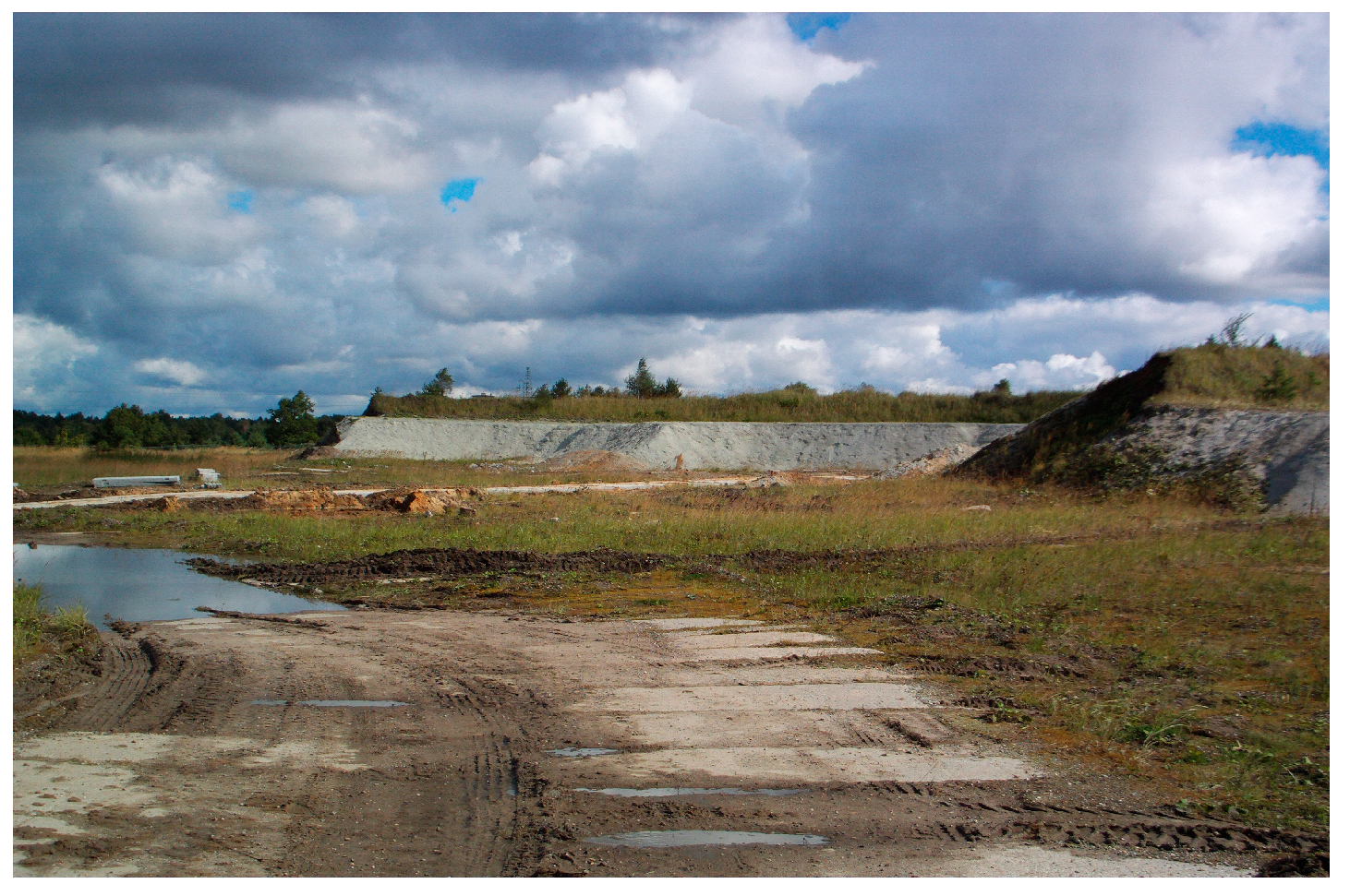
Figure 1. Fragment of the unprotected storage site for chemical plant waste.
Applsci 13 11485 g001
Figure 2. View of waste stored at area No. 5.
Applsci 13 11485 g002
Figure 3. (a) Soil mixed with cement grout, (b) cubic probes (15 cm samples).
Applsci 13 11485 g003
Figure 4. (a) Uniaxial compression test, (b) cubic probe after testing.
Applsci 13 11485 g004
Figure 5. Exemplary chart which shows the uniaxial compressive test performed on the soil–cement composite sample.
Applsci 13 11485 g005
Figure 6. Sample chart of the σ - τ f relation for a waste sample, ϕ = 33.8°, c = 22.9 kPa.
Applsci 13 11485 g006
Figure 7. Unit weight of cement-stabilized waste samples.
Applsci 13 11485 g007
Figure 8. Angle of shearing resistance of cement-stabilized waste samples.
Applsci 13 11485 g008
Figure 9. Cohesion of cement-stabilized waste samples.
Applsci 13 11485 g009
Figure 10. Numerical model (final state). The numbers given to soil layers correspond to the numbers in Table 3 below.
Applsci 13 11485 g010
Figure 11. Absolute displacement map, SF = 1.71.
Applsci 13 11485 g011
Figure 12. Absolute displacement map, SF = 1.91.
Applsci 13 11485 g012
Table 1. Tested physical and strength parameters of waste.
Mean
Value
Standard
Deviation
Characteristic Value
Unit weight [kN/m3]14.001.2814.64
Angle of shearing resistance [°]35.797.6231.98
Cohesion [kPa]37.6423.4625.91
Table 2. Results of mechanical parameters of the composite (strength and stiffness).
Time of Curing [Days]Soil–Cement CompositeSoil–Cement
Composite +
1.5% Active Carbon
compressive strength
[MPa]
72.547 2.729
283.7494.129
increase [%]32.1%33.9%
elastic modulus
[MPa]
7509.700 *374.780
28473.550540.260
increase [%]−7.6% *30.6%
unloading/reloading
elastic modulus
[MPa]
28768.420829.880
* Value 509.700 MPa looks like an outlier.
Table 3. Constitutive models and parameters in the FEM stability analysis.
Type of GroundCoulomb–Mohr Model
Performance Parameters
1.Ground, MSa, ID = 40%E = 68 MPa, ϕ = 32°, c = 1 kPa, ν = 0.26, γ = 18.5 kN/m3, ψ = 2°
2.Made groundE = 5 MPa, ϕ = 10°, c = 10 kPa, ν = 0.3, γ = 16 kN/m3, ψ = 0°
3.Earth dike (outer part) MSa, ID = 50%E = 80 MPa, ϕ = 33°, c = 1 kPa, ν = 0.25, γ = 18.5 kN/m3, ψ = 3°
4.Earth dike (inner part), landfill bottom, ClayE = 23 MPa, ϕ = 13°, c = 60 kPa, ν = 0.25, γ = 18.5 kN/m3, ψ = 3°
5.Drainage layer,
MSa, ID = 40%
E = 68 MPa, ϕ = 32°, c = 1 kPa, ν = 0.26, γ = 18.5 kN/m3, ψ = 2°
6.Compacted made groundsE = 10 MPa, ϕ = 20°, c = 10 kPa, ν = 0.2, γ = 18 kN/m3, ψ = 0°
7.Outer slopes,
compacted made grounds
E = 10 MPa, ϕ = 20°, c = 10 kPa, ν = 0.2, γ = 18 kN/m3, ψ = 0°
8.Cement stabilized wastesE = 10 MPa, ϕ = 32°, c = 26 kPa, ν = 0.3, γ = 14.6 kN/m3, ψ = 0°
9.Inner earth dike, compacted made groundsE = 10 MPa, ϕ = 20°, c = 10 kPa, ν = 0.2, γ = 18 kN/m3, ψ = 0°
Disclaimer/Publisher’s Note: The statements, opinions and data contained in all publications are solely those of the individual author(s) and contributor(s) and not of MDPI and/or the editor(s). MDPI and/or the editor(s) disclaim responsibility for any injury to people or property resulting from any ideas, methods, instructions or products referred to in the content.