Article

Modal and Structural Identification of Historic Bell Tower in Čuntić, Croatia Using Ambient Vibration Testing

Faculty of Civil Engineering, Architecture and Geodesy, University of Split, 21000 Split, Croatia
*
Author to whom correspondence should be addressed.
Appl. Sci. 2023, 13(20), 11494; https://doi.org/10.3390/app132011494
Submission received: 3 October 2023 / Revised: 15 October 2023 / Accepted: 19 October 2023 / Published: 20 October 2023
(This article belongs to the Section Acoustics and Vibrations)

Abstract

:
In this study, modal and structural identification of a historic masonry bell tower in Čuntići, Croatia, damaged during the recent Petrinja earthquake, was performed. The results of the ambient vibration tests (AVT) and operational modal analysis (OMA) were used to update the finite element numerical model of the bell tower. Three modes were experimentally determined: the first two were bending modes (f1 = 4.395 Hz and f2 = 4.639 Hz), and the third was a torsional mode (f3 = 10.303 Hz). The experimentally determined and the originally calculated (preliminary NM) modal shapes agreed well, but in terms of modal frequencies, the correlation was poor. After model updating, some structural parameters were identified, and a reliable finite element numerical model was established. The proposed method can provide a reliable evaluation of the structural parameters of historic masonry buildings.

1. Introduction

To understand the seismic behaviour and estimate the seismic resistance of historic masonry towers, finite element analyses of the structures are usually performed [1,2,3,4,5]. The most common difficulties in numerical modelling of such buildings are uncertainties related to design techniques, material properties, boundary conditions, soil-structure interaction, connection with surrounding buildings, if any, etc. For this reason, in the last decade, numerical modelling of the historic masonry tower has been supported by experimental studies of the structural parameters [6,7,8,9,10,11]. For this purpose, experimental modal analysis has proved to be indispensable, since the testing of the mechanical properties, i.e., the so-called static tests (e.g., flat-jack test or diagonal compression test) is known to be insufficient.
As mentioned earlier, the experimental estimation of modal parameters (natural frequencies, damping, and mode shapes) plays a very important role in evaluating the seismic behaviour of existing buildings. This estimation can be performed through both forced and ambient vibration tests. Forced vibration testing (FVT), also known as experimental modal analysis (EMA), is a technique in which the modal parameters of the structure are determined based on measured vibrations of the structure that are excited by known external forces. In contrast, ambient vibration testing (AMT), or operational modal analysis (OMA), is a technique in which the modal parameters of the structure are determined based on the measured ambient vibrations when the structure is under operating conditions. In civil engineering, OMA is very attractive because the tests are inexpensive, fast, and do not interfere with the normal use of the structure [12]. Lately, it has become the main experimental method for the assessment of the dynamic behaviour of full-scale structures, and it is especially suitable for historic masonry buildings.
On 29 December 2020, an earthquake of magnitude Mw 6.4 occurred in the central region of Croatia, near the town of Petrinja [13,14]. The intensity of the earthquake was VIII-IX according to the EMS scale. This was the strongest earthquake that had occurred recently in the Croatian region. The maximum ground acceleration at the epicentre of the earthquake was 114% of g, and the maximum ground velocity was 0.813 m/s at a depth of 13.5 km in the hypocenter. It is reported that 50,000 buildings were damaged. One of the reasons for the large number of damaged buildings is certainly that the main earthquake, the day before, was preceded by an earthquake of magnitude Mw 5.2. In the period between these two quakes, there were over a hundred weaker earthquakes in the region [13]. Numerous churches and sacral buildings were damaged or destroyed during this earthquake sequence. Usually, these are massive buildings with tall parts and large, awkward openings, making them exposed to large seismic loads. Therefore, the structures of such buildings are particularly vulnerable during an earthquake [13]. One such building is the bell tower of the Church of St. Anthony of Padua in Čuntić, Croatia, which was significantly damaged during this earthquake. In this seismic area, with the epicentre in Pokupsko, a strong earthquake of Mw 5.8–6.0 occurred in 1909. Based on the analysis of this earthquake, the famous Croatian geophysicist Andrija Mohorovičić discovered a discontinuity between the Earth’s crust and the mantle (the Mohorovičić discontinuity) [13].
The main objective of this research is the modal and structural identification of the bell tower in Čuntić, Croatia. The bell tower was damaged during the Petrinja earthquake in such a way that its functionality was compromised, so an evaluation of its seismic resistance is required. Recently, the application of the results of experimental determination of modal parameters with AMT for different buildings has gained importance [15,16,17,18,19,20,21,22,23,24,25,26,27,28,29,30,31,32,33,34]. Gentile and Saisi [15] presented the results of investigations based on ambient vibrations carried out to evaluate the structural condition of a masonry bell tower built in the XVII century and about 74 m high. The assessment procedure included full-scale vibration testing, modal identification from the ambient vibration responses, finite element modelling, and dynamics-based identification of the uncertain structural parameters of the model. Bayraktar et al. [17] presented the results of a vibration test and operational modal analysis performed on the historic masonry bell tower of Hagia Sophia Church in Trabzon, Türkiye. The experimental measurements were performed using two measurement setups at different times. In addition to the experimental measurements, an analytical model of the tower was developed. The authors report that good harmony is achieved between the mode shapes, but there are some differences between the natural frequencies. Standoli et al. [24] presented the results of a study carried out on four different isolated masonry bell towers in the province of Ferrara, Italy. The parameters of the materials were derived by calibrating finite element models (FEM), using data collected during a study campaign carried out with an OMA application. Recently, Trešnjo et al. [29] presented the results of a dynamic on-site investigation of a stone minaret in Mostar and provided a seismic evaluation. The on-site investigation included dynamic identification of the minaret through environmental vibration tests and qualitative assessment of the masonry through sound pulse velocity measurements. In addition to the modal analysis, the authors performed a time history analysis using the Applied Element Method. The authors reported good agreement between the first natural frequency obtained by the on-site investigation and the modal analysis. Azim and Gül [31] presented a new element-level damage detection framework for truss railroad bridges that combines acceleration and strain response analysis. They determined operational acceleration and strain responses to train passage and developed a new damage index by formulating a strategy to combine damage features obtained individually from acceleration and strain analysis. Castro and Zurita [32] presented the application of OMA to gears and induction motors, based on the random decrement technique and the extended Ibrahim time method. This work shows how far the application of OMA goes beyond monitoring the condition of structures in civil engineering.
In this work, ambient vibration tests and OMA were applied to determine the modal parameters of the masonry bell tower. The determination of modal parameters is necessary for updating, i.e., tuning, a numerical model that can be used to simulate the behaviour of the structure. The results of the OMA are then used for the identification of the structure. The ultimate goal of this study is to develop a finite element (FE) model in which the modal analysis results agree with the experimental results and which reliably simulates the behaviour of the tower.

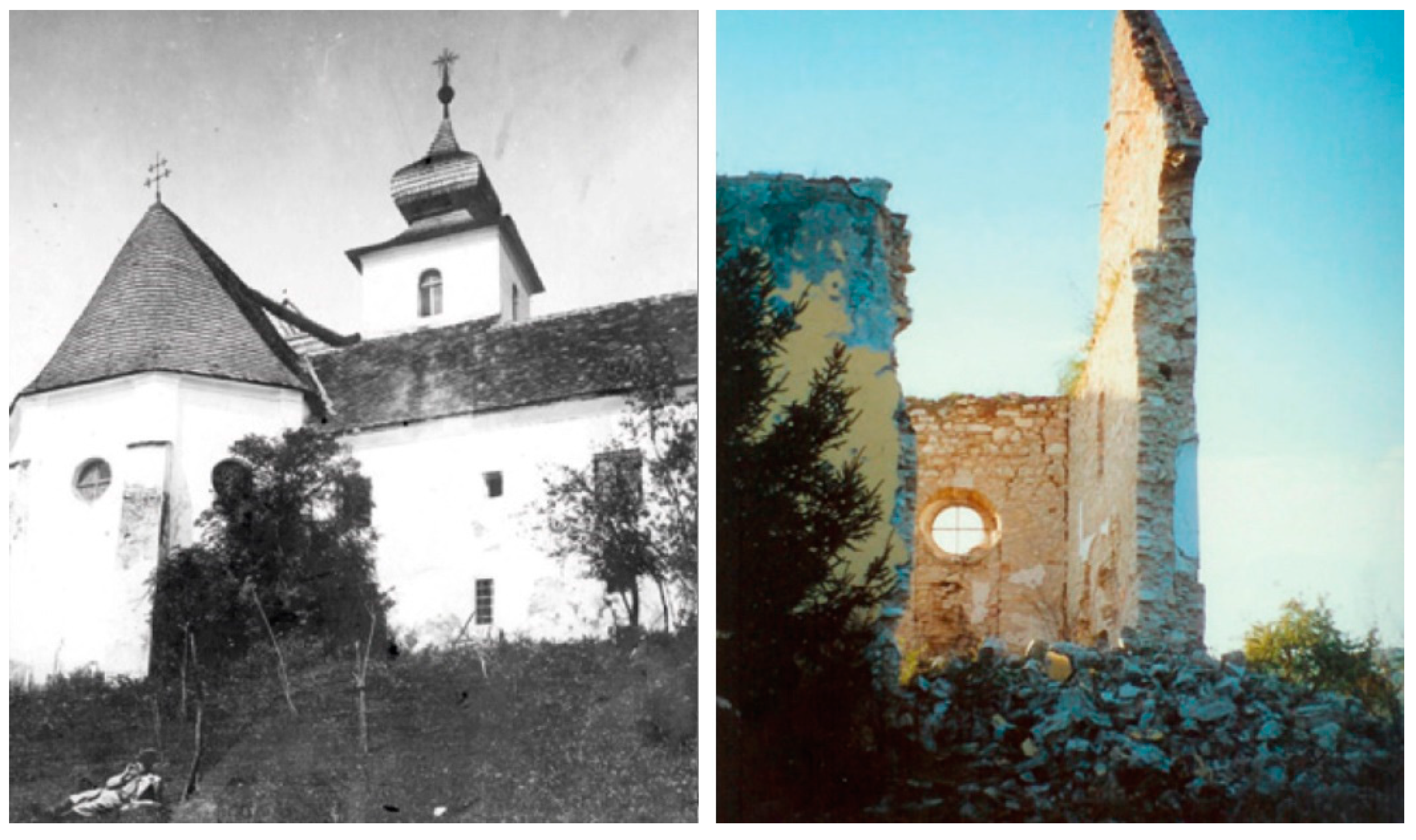
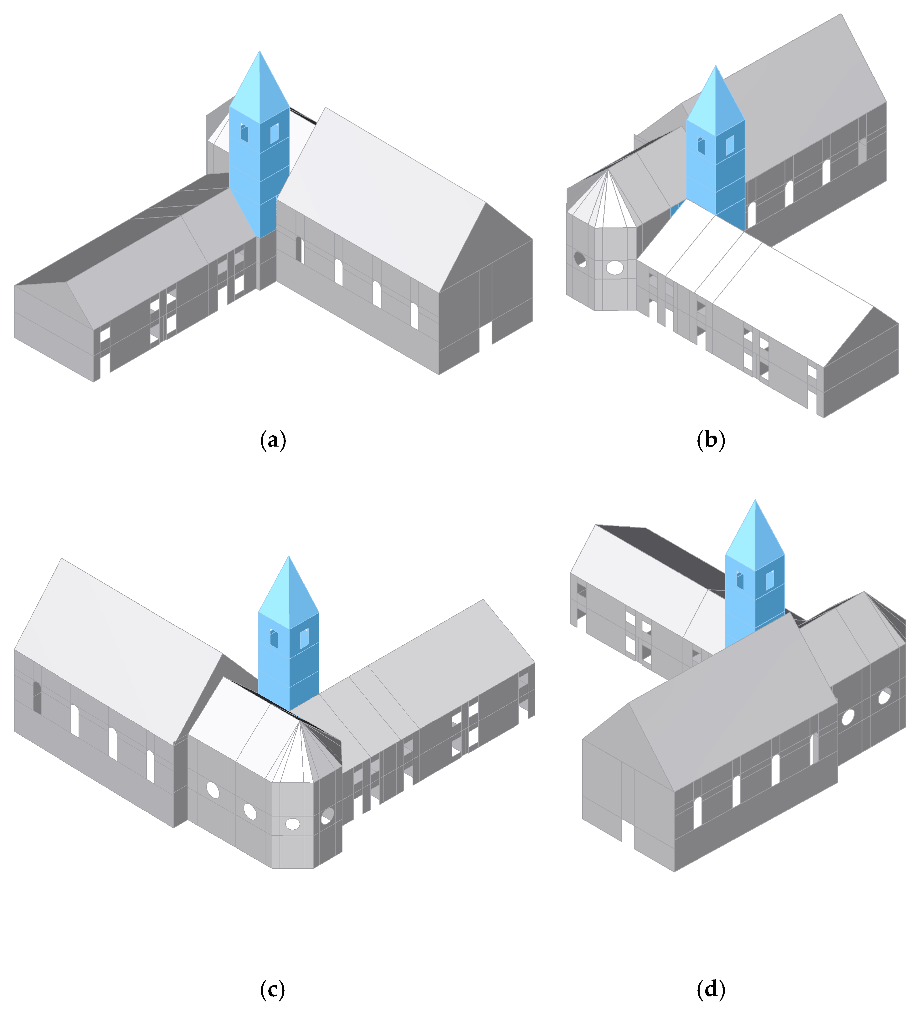
2. The Bell Tower of the Church of St. Anthony of Padua in Čuntić, Croatia

2.1. General Information

The bell tower is an integral part of the Church of St. Anthony of Padua and the Franciscan Monastery (Figure 1 and Figure 2). It is located in Čuntić, a village near the town of Petrinja in central Croatia.
The church and the monastery were built in 1770. Throughout history, they were repeatedly damaged and renewed. During the Croatian War of Independence, the Church and Monastery of St. Anthony of Padua were burned down by the occupiers on 26 July 1991 and mined on 19 February 1992 (Figure 3). During the last renovation, which began in 1996, the church and bell tower were restored to their original form.
The bell tower is connected to the parish hall on its southeast and southwest sides, to the church on its northeast side, and to the apse of the church on its northwest side. It has a rectangular floor plan of 5.22 m by 4.81 m (Figure 4a). The height of the bell tower (to its top) is approximately 18 m. The thickness of the bell tower is variable. The wall thickness decreases with increasing height, from 160 cm on the first floor to 45 cm on the top floor. Six levels of the bell tower can be distinguished, five of which are defined by a change in wall thickness (Figure 4b). At the top of the tower is the bell cell with three bells.
The structure of the church and the monastery, as well as the bell tower, is mainly made of masonry walls and reinforced concrete (RC) or wooden panels. The walls of the bell tower are made of different types of masonry and masonry elements. The walls of the bell tower were originally built of stone blocks (with lime mortar). During the last renovation, the stone blocks in some parts of the walls were replaced by clay bricks. The floor structure of the first floor and the attic is made of an RC slab, while the other floor structures are wooden planks supported on the offsets of the bell tower walls.

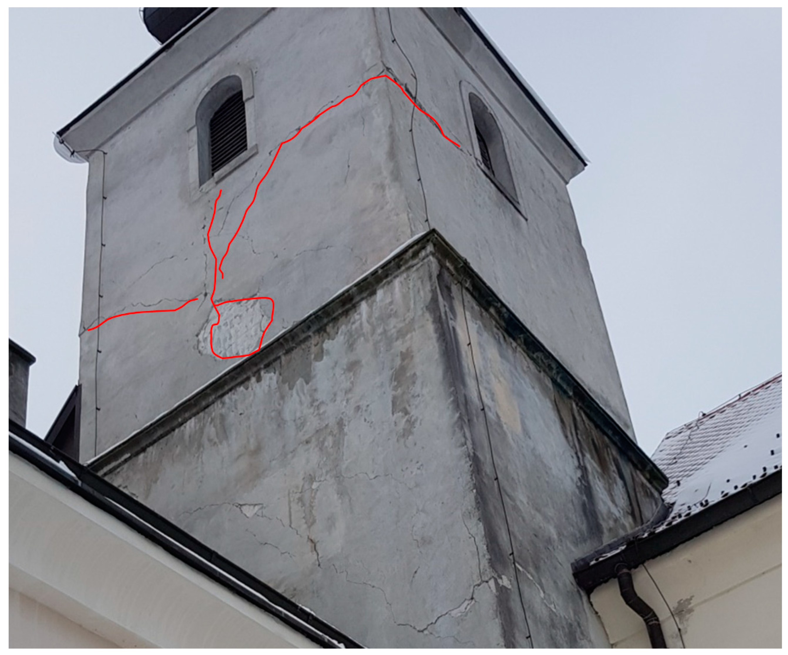
2.2. Damage Description

After the Petrinja earthquake, the Church of St. Anthony of Padua and the bell tower were severely damaged. In fact, it was the bell tower that suffered the most potentially dangerous damage. The crack patterns on the walls of the tower are shown in Figure 5 and Figure 6, which were determined by visual inspection. The deepest cracks were found at the top of the tower, around the openings, and at the interface with the church and monastery. Such a crack pattern and collapse mechanisms of the bell tower are expected based on the surrounding buildings. No significant damage was observed on the visible parts of the tower shaft.

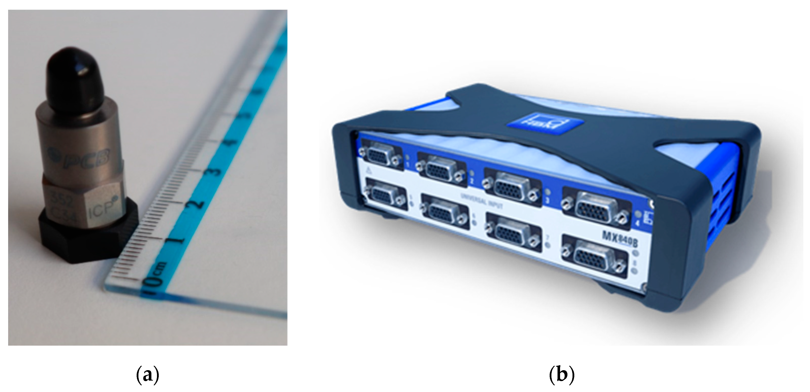
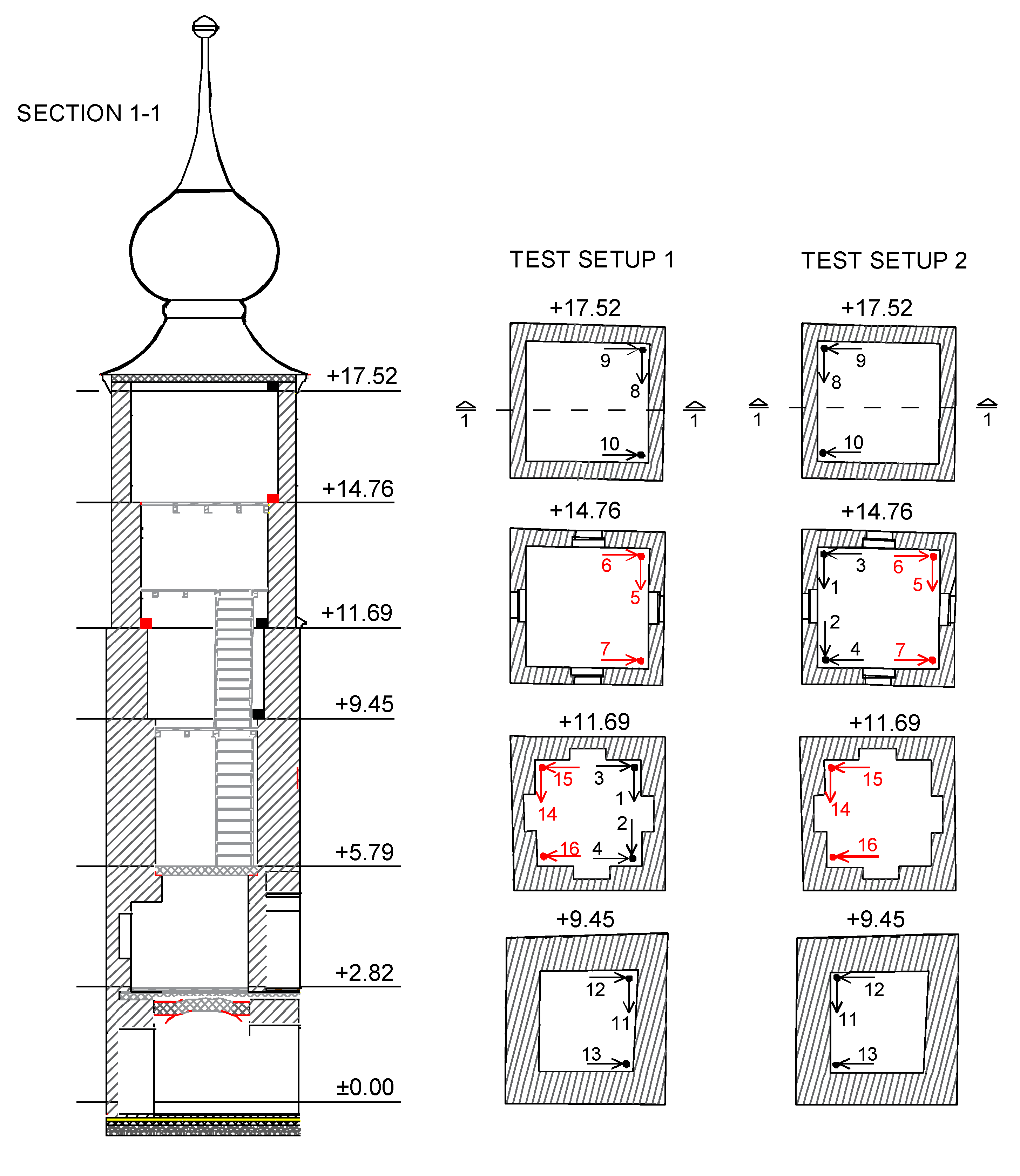
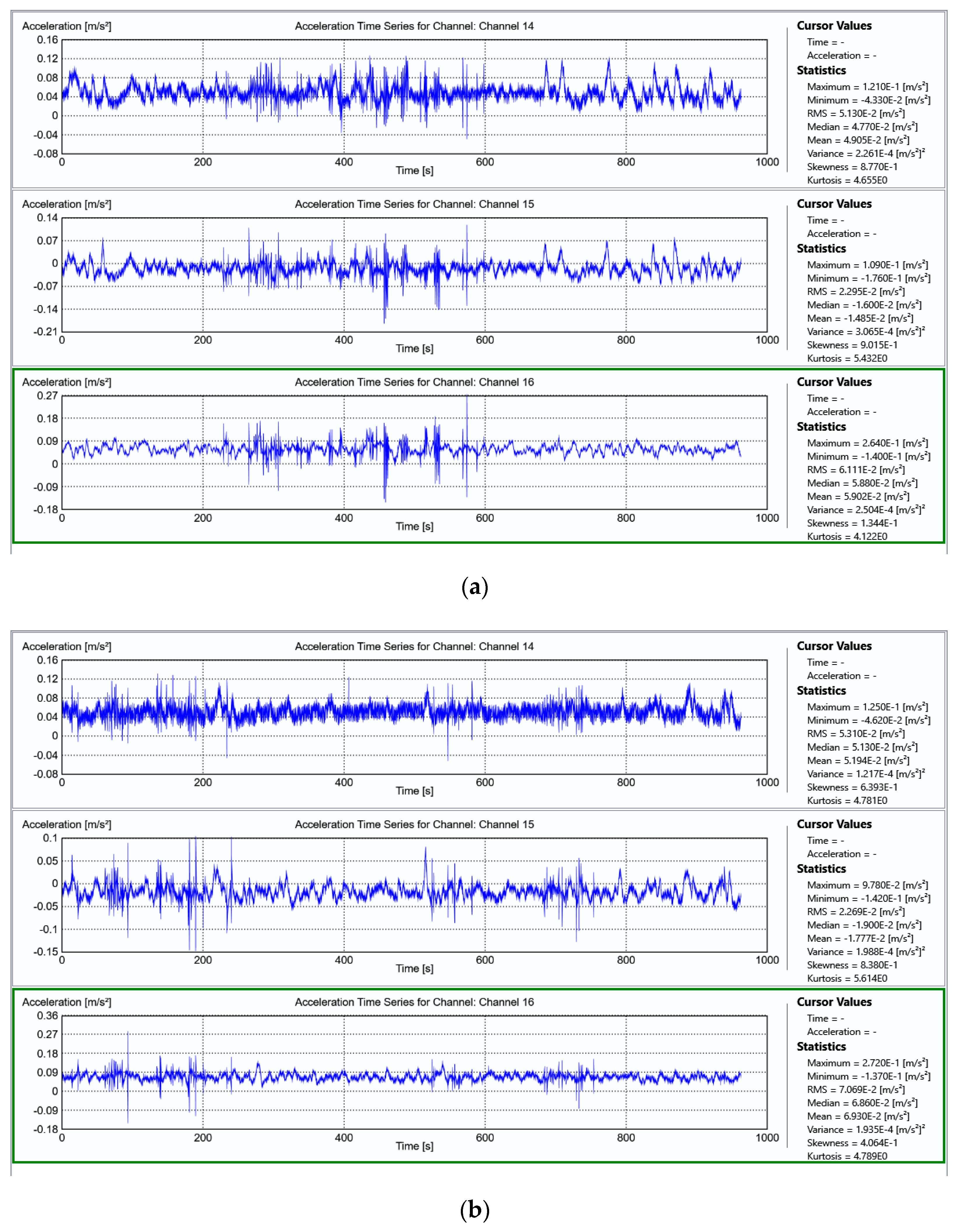
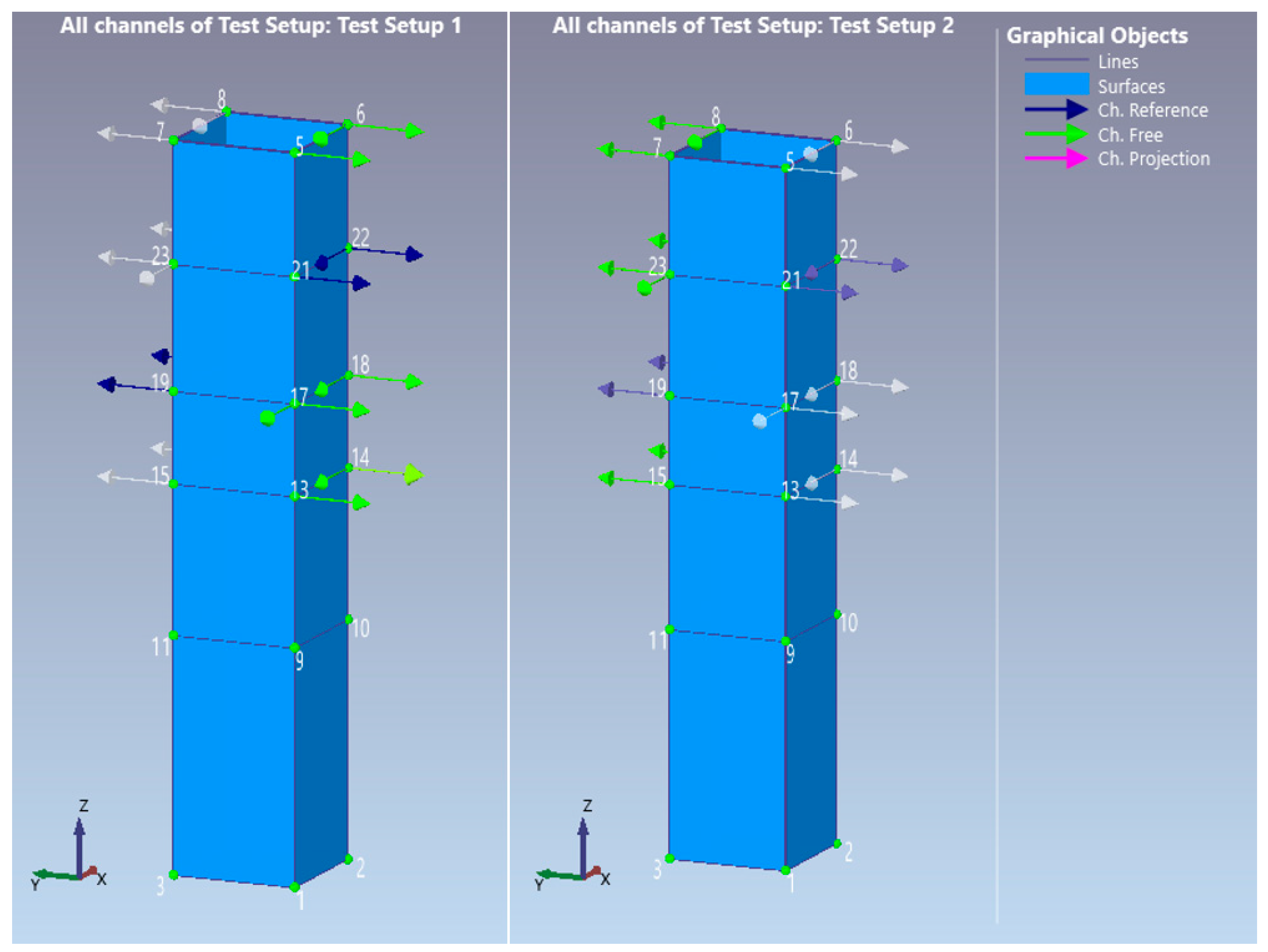
3. Ambient Vibration Testing

On 7 and 8 July 2022, the authors conducted an ambient vibration test on the bell tower. Single-axis piezoelectric accelerometers (Figure 7a), manufactured by PCB Piezotronics, Inc., were used to measure the vibrations (accelerations) of the structure. The tests were performed using two Hottinger Baldwin Messtechnik (HBM) QuantumX 8-channel data acquisition systems (Figure 7b).
To determine the modal parameters of the bell tower, horizontal accelerations were measured at 16 measurement points on the tower walls at four different levels corresponding to the height of the bell tower: h1 = 9.45 m; h2 = 11.69 m; h3 = 14.76 m; and h4 = 17.52 m (Figure 8). Given the limited measurement resources and the author’s desire to measure the acceleration of the bell tower at as many points as possible, the measurement is divided into two sets: TEST SETUP 1 and TEST SETUP 2. The arrangement of six accelerometers remained unchanged for both setups (so-called reference accelerometers). For the first set of measurements, most accelerometers were placed on the southeast side of the bell tower, and for the second set of measurements, most accelerometers were placed on the northwest side of the bell tower. The location of the measurement points and the arrangement of the reference accelerometers were carefully selected according to the expected modal shapes of the bell tower.
At each measurement point, each accelerometer was attached to a steel cube (20 × 20 × 20 mm). Each cube was welded to steel plates (80 × 80 mm), which were attached to the inside of the tower walls with screws (Figure 9). This type of sensor attachment ensures measurement in two orthogonal directions at the measurement points where the two accelerometers are attached.
In both test setups, the accelerations of the bell tower structure were measured and recorded for 960 s (16 min). The duration of the measurement was chosen to comply with a widely accepted recommendation: the length of the time windows should be at least 2000-T1, where T1 is the period of the assumed fundamental vibration of the structure [37]. During the measurement, the structure was excited by the action of the wind, by micro-vibrations caused by the movement of people, and by the strikes of the small bells of the bell tower. Examples of the acceleration time histories recorded during the tests can be found in Figure 10. It is noteworthy that only a very small amount of ambient excitation was present during the tests. The maximum recorded acceleration is less than 0.6 m/s2; it is recorded by the sensor at measurement point seven during TEST SETUP 1 and is probably caused by vibrating bells (Figure 11). The sampling rate was 200 Hz, which is much higher than required because the significant frequency content of the signals for the studied structure is below 20 Hz.

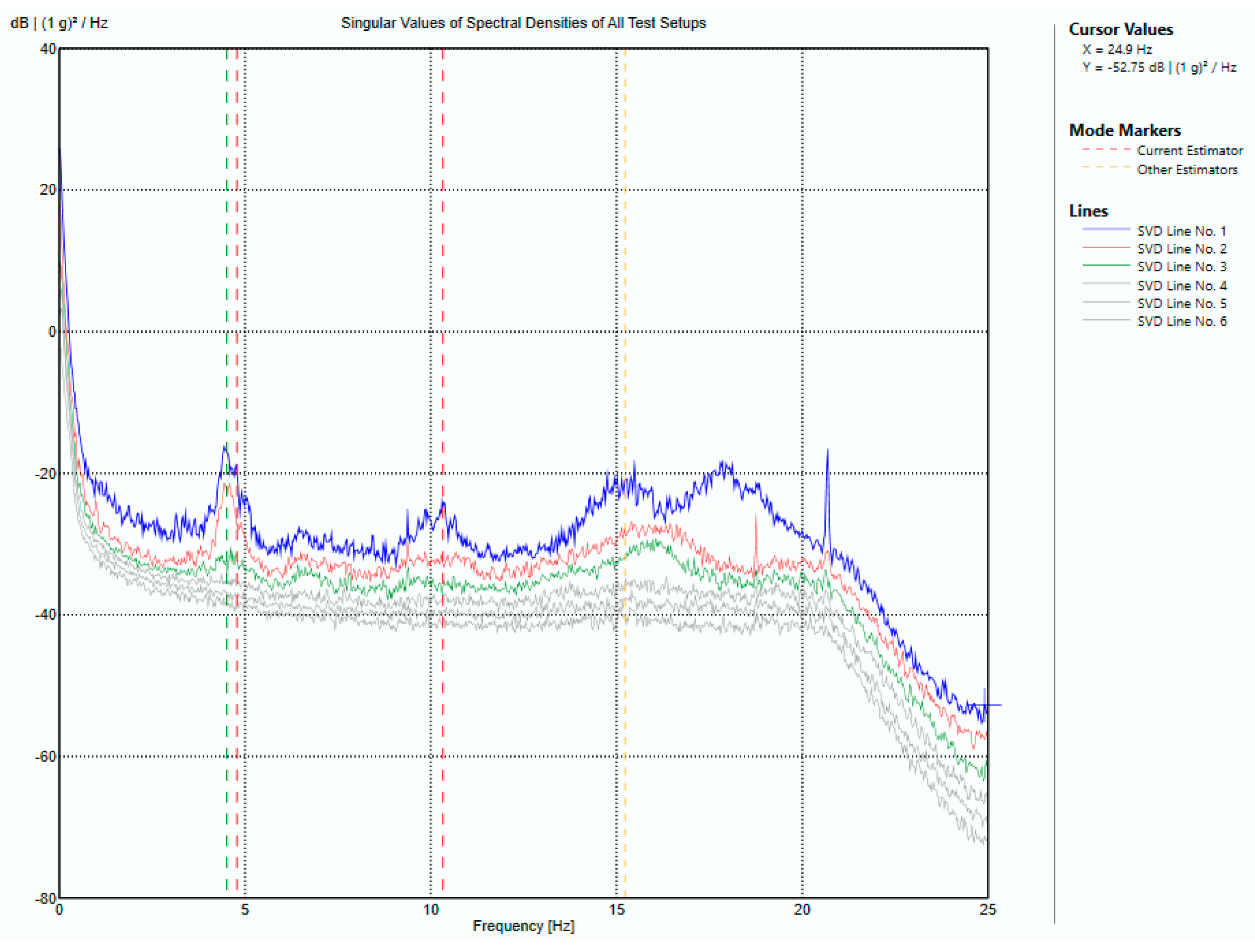
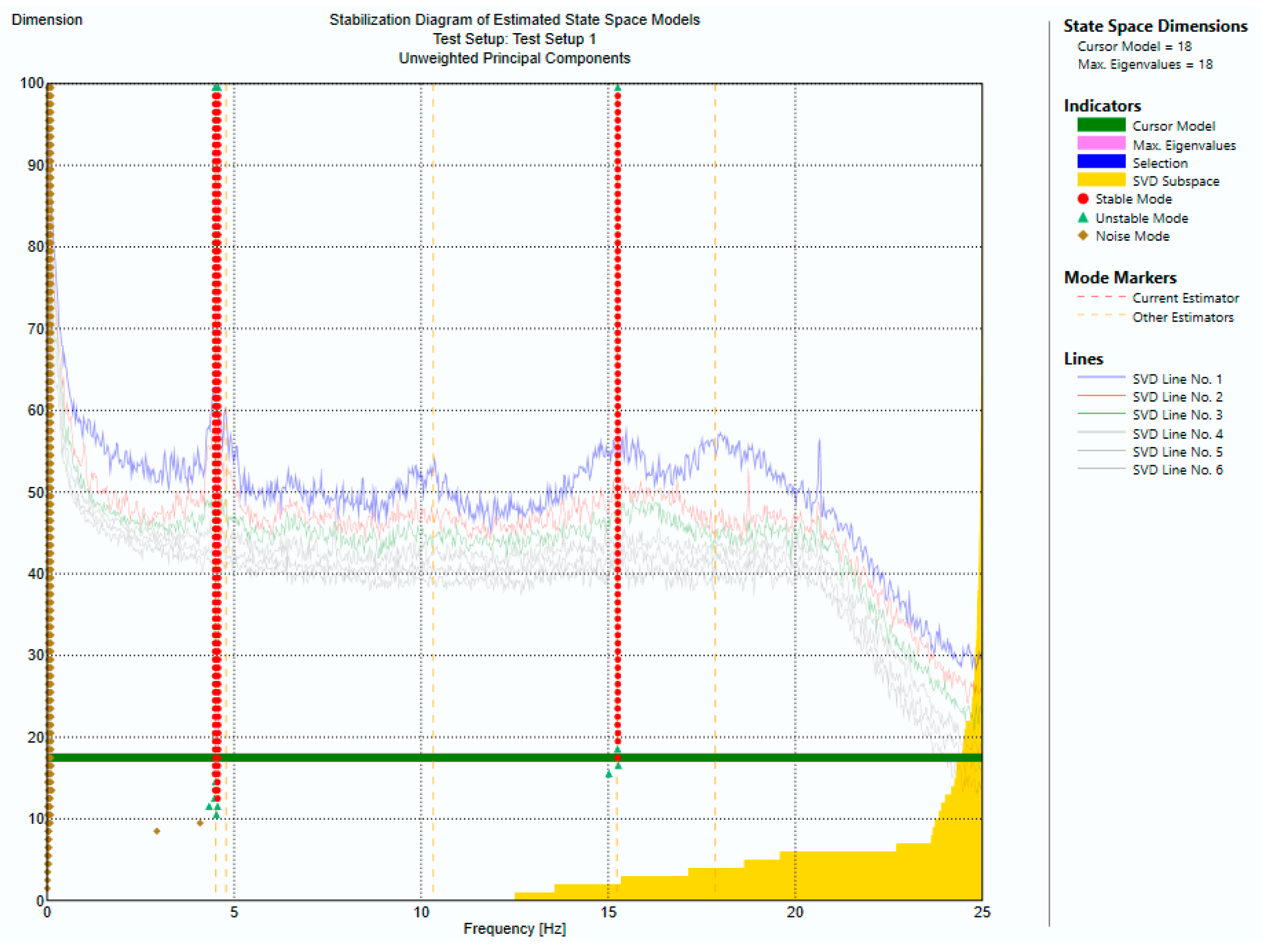
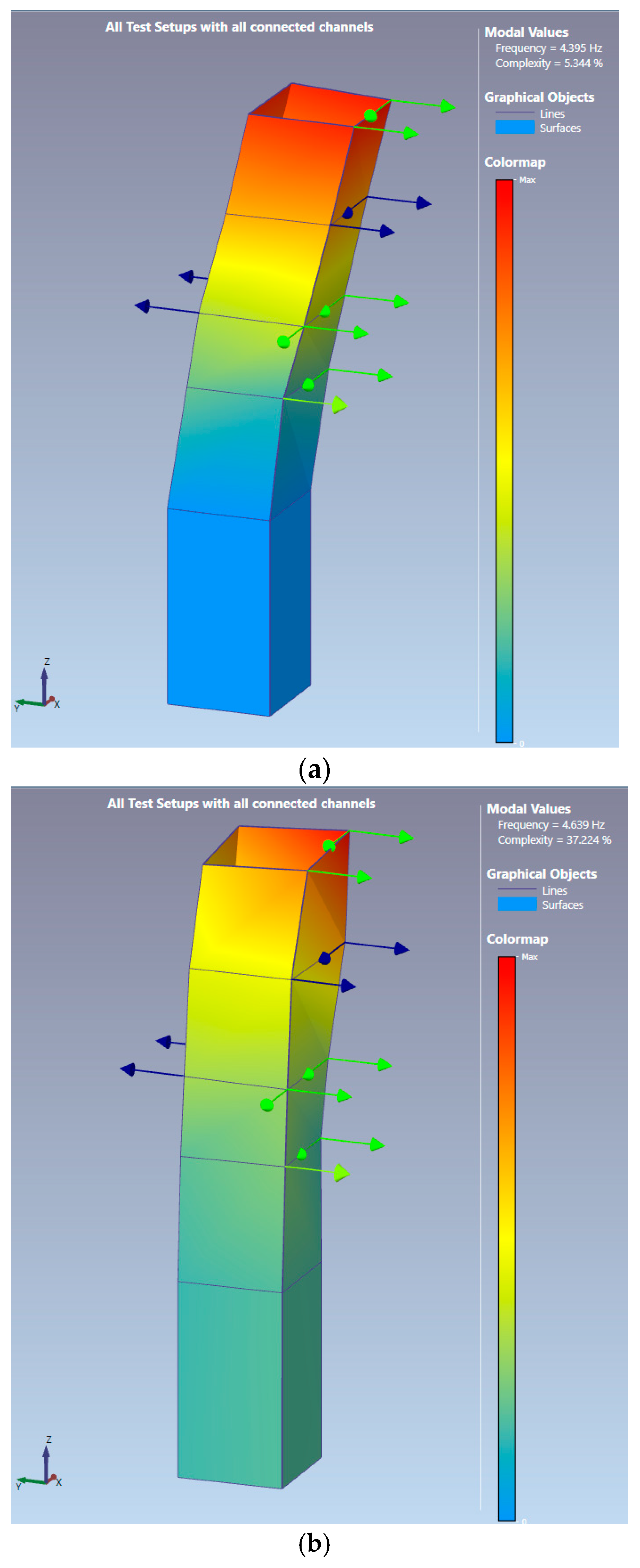
4. Operational Modal Analysis (OMA)

To obtain the modal parameters of the structures, operational modal analysis (OMA) is used. The extraction of the modal parameters from the recorded data was performed using ARTeMIS 2.13 software [38]. Figure 12 shows the model used to identify the modal parameters of the bell tower. Prior to processing, the recorded data was filtered with a low-pass filter and decimated to the 0–25 Hz frequency range of interest. These 16 min of data were segmented and processed with a frequency resolution of 1024.
In this work, modal parameter identification was performed by two different techniques: enhanced frequency domain decomposition (EFDD) and stochastic subspace identification-unweighted principal components (SSI-UPC). The EFDD technique is an enhanced system identification technique that results only from frequency domain decomposition and provides a more accurate estimate of natural frequencies and mode shapes. This technique is suitable for closely spaced modes and repeated modes but has drawbacks in accurately identifying damping [39]. The SSI technique is a stochastic method for estimating system matrices from measured oscillations based on an algorithm developed by Van Overschee et al. [40]. Unweighted Principal Component (UPC), the simplest SSI algorithm, is used in this work because it has the highest estimation accuracy compared to other algorithms [41,42].
Figure 13 shows the singular values of the spectral density matrices obtained using the EFDD technique, while Figure 14 shows the stabilization diagram of the state-space models obtained using the SSI-UPC technique. Despite the relatively low vibrations during the vibration test, the modal parameters of the bell tower structure are identified. From the EFDD results (Figure 13), it is clear that the natural frequencies of the bell tower are in the range of 1 to 20 Hz. Table 1 shows the frequencies, damping and complexity (or the so-called MCF factor) of the selected modes. The modes were selected based on the criterion that the modes with the lowest complexity should be chosen [43].
Unfortunately, the ambient excitation did not sufficiently excite the upper modes of the bell tower since the building is located in a traffic-free area. Only three modes, described in Table 1 and shown in Figure 15, were detected. It is obvious that the first and second modes are bending modes (in two orthogonal directions), while the third mode can be classified as a torsional mode. It can also be highlighted that the first two modes are very close to each other. It is a consequence of the almost equal bending stiffness of the bell tower in two orthogonal directions (square cross-section) and boundary conditions, i.e., supports of the bell tower (surrounding buildings).

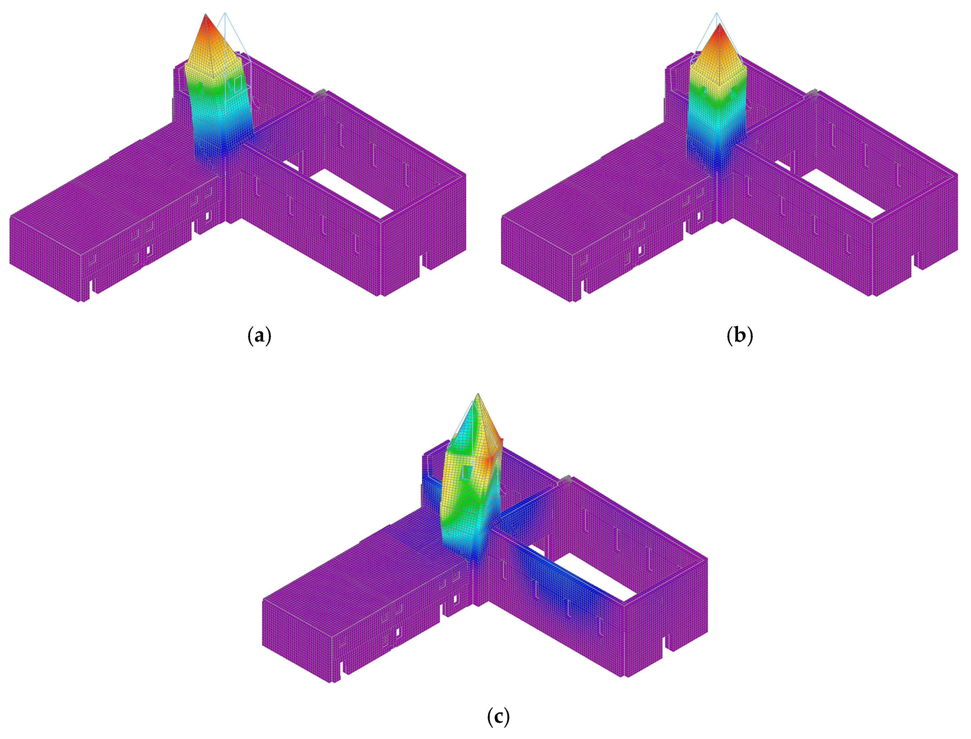
5. FE Modelling and Model Updating

After experimental measurements and the determination of the real dynamic behaviour, a three-dimensional numerical model was created based on the finite element method (FEM) using SCIA Engineer 22.1 software [44]. The model was created according to the real geometry of the object, which was recorded with a 3D ground scanner.
The load-bearing structure consists of three materials: masonry (stone blocks and lime-cement mortar), RC deck on the first floor and attic of the monastery, and wood for the roof. A detailed description of the load-bearing structure can be found in Section 2.1. Great attention was paid to the adequate modelling of all parameters affecting the dynamic properties: mass distribution, wall thickness (Figure 4b), openings, lintels, deck, stairs and roof. Secondary structural elements that are not essential to the stiffness of the model are not modelled, but their mass is added to the walls.
The structure is modelled with four nodes, 2D shell elements. A mesh of finite elements of size 0.3 × 0.3 m (31,000 elements in total) was used.
Mindlin bending theory and direct solution method are used. The direct solution method is a standard Cholesky solution based on a decomposition of the matrix of the system. The advantage is that it can solve multiple right-hand sides simultaneously.
Dynamic eigenmode analysis (determination of modal shapes and modal frequencies) is performed using subspace iteration. The subspace iteration method was introduced by Krylov [45] and improved by K. J. Bathe [46,47]. The mass is distributed over the surface of the element [44]. Figure 16 shows the rendered numerical model (NM).
For the preliminary NM, the elastic parameters of the material were adopted according to Table 2. In this model, the same quality of masonry was assumed in the church, the monastery and the bell tower. The bell cell with three bells on the top of the tower was simulated as an additional mass of 1000 kg.
A numerical analysis was performed to determine the modal shapes and modal frequencies. The first three modes and their dynamic properties are shown in Table 3 and Figure 17. When we compare the experimentally determined modal shapes and the numerically determined ones, we see that they agree relatively well. We see a large difference in modal frequencies due to inadequate modelling of the elastic modulus of the walls (masonry), which has a lower value than the assumed value at the bell tower, which was severely damaged in the earthquake.
The recalibration was performed in an indirect way by changing the mechanical parameters of the bell tower walls (elastic modulus E and bulk density φ). The reduction was performed on two bell tower levels by height, as shown in Table 4 and Figure 8.
The modal shapes and the difference between the calibrated numerical and experimental results obtained at the end of the last step are shown in Table 5 and Figure 18.

6. Discussion

The analysis conducted in this work shows the modal and structural identification of the bell tower of the Church in Čuntić, Croatia. The main objective of this study is to characterise the behaviour of the damaged masonry and the interaction between the tower and the surrounding buildings. Although this is an isolated case, it shows that the influence of the material parameters assumed for the calculation is important, especially in the presence of a significant condition of the damaged buildings. Often, the structural identification of existing building structures is preceded by the experimental and local determination of individual material parameters. However, this is not sufficient, and as an alternative, this study proposes a procedure that involves the experimental determination of modal parameters based on the analysis of vibrations under operating conditions. In addition, a considerable effort is required to define a reliable numerical model that can effectively represent the determined experimental modal parameters.

7. Conclusions

In order to assess the condition of the structure and determine the degree of earthquake resistance of the bell tower of the parish Church in Čuntić, an OMA was performed under ambient conditions.
Accelerations of the bell tower walls were measured in two sets at a total of 16 measurement points, where the vibrations of the bell tower were caused by the wind, micro-vibrations from the movement of people and the ringing of the bells. The analysis of the measured signals was performed using the EFDD and SSI-UPC techniques. The first two identified modes can be classified as bending (f1 = 4.395 Hz and f2 = 4.639 Hz), and the third identified mode can be classified as torsion (f3 = 10.303 Hz). Despite the very low ambient vibrations during the AVT, the OMA proved to be effective in identifying the modal parameters.
The comparison between the measured and the originally calculated modal parameters (preliminary NM) served to verify the assumptions used in the formulation of NM. In particular, a good correlation between experimental and numerical modal shapes was obtained for relatively high values of the elastic modulus of the bell tower masonry. However, the correlation between experimental and numerical results in terms of modal frequencies is rather poor. This, in addition to the visible damage, is an indication that it is more reasonable to choose a much lower value for the model E-modulus of the masonry in the most damaged areas of the bell tower. After updating NM (with significantly smaller values of elastic modulus varying by tower height), a good correlation between the experimental and numerical modal behaviour was obtained. Therefore, the numerical model with the assumed material and geometry properties is reliable for evaluating the seismic resistance of the bell tower.
It has been shown that the differences between the provisionally established and the finally adopted structural parameters are significant. In this sense, the contribution of AVT is very important because, based on the results of the OMA, the actual structural parameters of the building can be determined. The application of the proposed method can provide a reliable assessment of the seismic safety of historic buildings, as well as their resistance to other forces.

Author Contributions

Conceptualization, M.S. and I.B.; methodology, M.S., I.B., N.G. and A.B.; software, M.S. and I.B.; validation, M.S., I.B., N.G. and A.B.; formal analysis, M.S., I.B., N.G. and A.B.; investigation, M.S., I.B., N.G. and A.B.; resources, N.G.; data curation, M.S., I.B., N.G. and A.B.; writing—original draft preparation, M.S. and I.B.; writing—review and editing, N.G. and A.B.; visualization, M.S. and I.B.; supervision, A.B.; funding acquisition, N.G. All authors have read and agreed to the published version of the manuscript.

Funding

This research is partially supported by project KK.01.1.1.02.0027, a project co-financed by the Croatian Government and the European Union through the European Regional Development Fund—the Competitiveness and Cohesion Operational Programme.

Institutional Review Board Statement

Not applicable.

Informed Consent Statement

Not applicable.

Data Availability Statement

Not applicable.

Conflicts of Interest

The authors declare no conflict of interest.

References

  1. Lourenco, P.B. Computations on historic masonry structures. Prog. Struct. Eng. Mater. 2002, 4, 301–319. [Google Scholar] [CrossRef]
  2. Betti, M.; Vignoli, A. Modelling and analysis of a Romanesque church under earthquake loading: Assessment of seismic resistance. Eng. Struct. 2008, 30, 352–367. [Google Scholar] [CrossRef]
  3. Bayraktar, A.; Şahin, A.; Özcan, D.M.; Yıldırım, F. Numerical damage assessment of Haghia Sophia bell tower by nonlinear FE modeling. Appl. Math. Model. 2010, 34, 92–121. [Google Scholar] [CrossRef]
  4. Foraboschi, P. Church of San Giuliano di Puglia: Seismic repair and upgrading. Eng. Fail. Anal. 2013, 33, 281–314. [Google Scholar] [CrossRef]
  5. Bartoli, G.; Betti, M.; Vignoli, A. A numerical study on seismic risk assessment of historic masonry towers: A case study in San Gimignano. Bull. Earthq. Eng. 2016, 14, 1475–1518. [Google Scholar] [CrossRef]
  6. Saisi, A.; Gentile, C. Post-earthquake diagnostic investigation of a historic masonry tower. J. Cult. Herit. 2015, 16, 602–609. [Google Scholar] [CrossRef]
  7. Saisi, A.; Gentile, C.; Ruccolo, A. Pre-diagnostic prompt investigation and static monitoring of a historic bell-tower. Constr. Build. Mater. 2016, 122, 833–844. [Google Scholar] [CrossRef]
  8. da Silva Gonçalves, L.M.; Rodrigues, H.; Gaspar, F. Nondestructive Techniques for the Assessment and Preservation of Historic Structures; CRC Press: Boca Raton, FL, USA, 2017. [Google Scholar]
  9. Pavlovic, M.; ·Trevisani, S.; Cecchi, A. A procedure for the structural identification of masonry towers. J. Nondestruct. Eval. 2019, 38, 38. [Google Scholar] [CrossRef]
  10. Saisi, A.; Gentile, C. Investigation Strategy for Structural Assessment of Historic Towers. Infrastructures 2020, 5, 106. [Google Scholar] [CrossRef]
  11. Bartoli, G.; Betti, M.; Galano, L.; Pieraccini, M. Seismic Assessment of Historic Masonry Towers: Non-invasive Techniques and Analysis Methodologies. In Handbook of Cultural Heritage Analysis; D’Amico, S., Venuti, V., Eds.; Springer: Cham, Switzerland, 2022; pp. 1221–1268. [Google Scholar]
  12. Rainieri, C.; Fabbrocino, G. Operational Modal Analysis of Civil Engineering Structures: An Introduction and Guide for Applications; Springer: New York, NY, USA; Heidelberg, Germany; Dordrecht, The Netherlands; London, UK, 2014; Volume 2. [Google Scholar]
  13. Radnić, J.; Grgić, N.; Buzov, A.; Banović, I.; Smilović Zulim, M.; Baloević, G.; Sunara, M. Mw 6.4 Petrinja earthquake in Croatia: Main earthquake parameters, impact on buildings and recommendation for their structural strengthening. Gradevinar 2021, 73, 1109–1128. [Google Scholar]
  14. Atalić, J.; Demšić, M.; Baniček, M.; Uroš, M.; Dasović, I.; Prevolnik, S.; Kadić, A.; Šavor Novak, M.; Nastev, M. The December 2020 Magnitude (Mw) 6.4 Petrinja Earthquake, Croatia: Seismological Aspects, Emergency Response and Impacts. Res. Sq. 2022, 21, 1–42. [Google Scholar] [CrossRef]
  15. Gentile, C.; Saisi, A. Ambient vibration testing of historic masonry towers for structural identification and damage assessment. Constr. Build. Mater. 2007, 21, 1311–1321. [Google Scholar] [CrossRef]
  16. Barsotti, R.; Bennati, S.; Nardini, L.; Salvatore, W. Characterisation of the mechanical behaviour of the bell tower of the cathedral of San Miniato (Pisa). WIT Trans. Built Environ. 2008, 98, 343–355. [Google Scholar]
  17. Bayraktar, A.; Türker, T.; Sevım, B.; Altunişik, A.C.; Yildirim, F. Modal parameter identification of Hagia Sophia bell-tower via ambient vibration test. J. Nondestruct. Eval. 2009, 28, 37–47. [Google Scholar] [CrossRef]
  18. Foti, D.; Diaferio, M.; Giannoccaro, N.I.; Mongelli, M. Ambient vibration testing, dynamic identification and model updating of a historic tower. NDT E Int. 2012, 47, 88–95. [Google Scholar] [CrossRef]
  19. Bartoli, G.; Betti, M.; Giordano, S. In situ static and dynamic investigations on the “Torre Grossa” masonry tower. Eng. Struct. 2013, 52, 718–733. [Google Scholar] [CrossRef]
  20. Ranieri, C. On the Estimation of the Fundamental Modal Properties of Italian Historical Masonry Towers. 2014. Available online: https://iris.unimol.it/handle/11695/48344 (accessed on 28 February 2023).
  21. Gentile, C.; Saisi, A.; Cabboi, A. Structural identification of a masonry tower based on operational modal analysis. Int. J. Archit. Herit. 2015, 9, 98–110. [Google Scholar] [CrossRef]
  22. Ferraioli, M.; Miccoli, L.; Abruzzese, D.; Mandara, A. Dynamic characterisation and seismic assessment of medieval masonry towers. Nat. Hazards 2017, 86, 489–515. [Google Scholar] [CrossRef]
  23. Diaferio, M.; Foti, D.; Potenza, F. Prediction of the fundamental frequencies and modal shapes of historic masonry towers by empirical equations based on experimental data. Eng. Struct. 2018, 156, 433–442. [Google Scholar] [CrossRef]
  24. Standoli, G.; Giordano, E.; Milani, G.; Clementi, F. Model Updating of Historical Belfries Based on Oma Identification Techniques. Int. J. Arch. Herit. 2020, 15, 132–156. [Google Scholar] [CrossRef]
  25. Torelli, G.; D’Ayala, D.; Betti, M.; Bartoli, G. Analytical and numerical seismic assessment of heritage masonry towers. Bull. Earthq. Eng. 2020, 18, 969–1008. [Google Scholar] [CrossRef]
  26. Capanna, I.; Cirella, R.; Aloisio, A.; Alaggio, R.; Di Fabio, F.; Fragiacomo, M. Operational Modal Analysis, Model Update and Fragility Curves Estimation, through Truncated Incremental Dynamic Analysis, of a Masonry Belfry. Buildings 2021, 11, 120. [Google Scholar] [CrossRef]
  27. Kita, A.; Cavalagli, N.; Venanzi, I.; Ubertini, F. A new method for earthquake-induced damage identification in historic masonry towers combining OMA and IDA. Bull. Earthq. Eng. 2021, 19, 5307–5337. [Google Scholar] [CrossRef]
  28. Milani, G.; Clementi, F. Advanced Seismic Assessment of Four Masonry Bell Towers in Italy after Operational Modal Analysis (OMA) Identification. Int. J. Archit. Herit. 2021, 15, 157–186. [Google Scholar] [CrossRef]
  29. Trešnjo, F.; Humo, M.; Casarin, F.; Ademović, N. Experimental Investigations and Seismic Assessment of a Historical Stone Minaret in Mostar. Buildings 2023, 13, 536. [Google Scholar] [CrossRef]
  30. Lariviere, O.; Chadefaux, D.; Sauret, C.; Kordulas, L.; Thoreux, P. Modal Characterization of Manual Wheelchairs. Vibration 2022, 5, 442–463. [Google Scholar] [CrossRef]
  31. Azim, M.R.; Gül, M. Development of a Novel Damage Detection Framework for Truss Railway Bridges Using Operational Acceleration and Strain Response. Vibration 2021, 4, 422–443. [Google Scholar] [CrossRef]
  32. Castro, G.; Zurita, G. Applications of Operational Modal Analysis in Gearbox and Induction Motor, Based on Random Decrement Technique and Enhanced Ibrahim Time Method. Appl. Sci. 2022, 12, 5284. [Google Scholar] [CrossRef]
  33. Wang, C.; Huang, H.; Lai, X.; Chen, J. A new online operational modal analysis method for vibration control for linear time-varying structure. Appl. Sci. 2020, 10, 48. [Google Scholar] [CrossRef]
  34. Fu, W.; Wang, C.; Chen, J. Operational modal analysis for vibration control following moving window locality preserving projections for linear slow-time-varying structures. Appl. Sci. 2021, 11, 791. [Google Scholar] [CrossRef]
  35. Official Site of the Diocese of Sisak. Available online: https://biskupija-sisak.hr/biskupija-2/krizni-put-sisacke-crkve/ (accessed on 13 February 2023).
  36. Official Site of HBM. Available online: https://www.hbm.com/en/ (accessed on 17 February 2023).
  37. Cantieni, R. Experimental methods used in system identification of civil engineering structures. In Proceedings of the 1st International Operational Modal Analysis Conference (IOMAC-2005), Aalborg, Denmark, 26–27 April 2005. [Google Scholar]
  38. Structural Vibration Solutions ApS. ARTeMIS Modal Pro Software, version 7.0; NOVI Science Park: Aalborg, Denmark, 2021.
  39. Hasan, M.D.A.; Ahmad, Z.A.B.; Salman Leong, M.; Hee, L.M. Enhanced frequency domain decomposition algorithm: A review of a recent development for unbiased damping ratio estimates. J. Vibroeng. 2018, 20, 1919–1936. [Google Scholar] [CrossRef]
  40. Van Overschee, P.; De Moor, B.L.; Hensher, D.A.; Rose, J.M.; Greene, W.H.; Train, K.; Greene, W.; Krause, E.; Gere, J.; Hibbeler, R. Subspace Identification for the Linear Systems: Theory–Implementation-Application; Katholieke Universiteit Leuven: Leuven, Belgium; Kluwer Academic Publishers: Boston, MA, USA, 1996. [Google Scholar]
  41. Cismasiu, C.; Narciso, A.C.; Amarante dos Santos, F.P. Experimental dynamic characterization and finite-element updating of a footbridge structure. J. Perform. Constr. Facil. 2014, 29, 4014116. [Google Scholar] [CrossRef]
  42. Shokravi, H.; Shokravi, H.; Bakhary, N.; Rahimian Koloor, S.S.; Petrů, M. A Comparative Study of the Data-Driven Stochastic Subspace Methods for Health Monitoring of Structures: A Bridge Case Study. Appl. Sci. 2020, 10, 3132. [Google Scholar] [CrossRef]
  43. Brincker, R.; Zhang, L.; Andersen, P. Modal identification from ambient responses using frequency domain decomposition. In Proceedings of the 18th International Modal Analysis Conference (IMAC), San Antonio, TX, USA, 7–10 February 2000; pp. 625–630. [Google Scholar]
  44. Official Site of the SCIA Engineer. Available online: https://www.scia.net/en/scia-engineer (accessed on 13 February 2023).
  45. Dongarra, J.; Sullivan, F. Guest editors’ introduction to the top 10 algorithms. Comput. Sci. Eng. 2000, 2, 22–23. [Google Scholar] [CrossRef]
  46. Bathe, K.J. Solution Methods for Large Generalized Eigenvalue Problems in Structural Engineering; Report UCSESM 71-20; Department of Civil Engineering, University of California, Berkeley: Berkeley, CA, USA, 1971. [Google Scholar]
  47. Bathe, K.J. The subspace iteration method—Revisited. Comput. Struct. 2013, 126, 177–183. [Google Scholar] [CrossRef]
Figure 1. The bell tower facade: (a) northeast; (b) southeast; (c) southwest.
Applsci 13 11494 g001
Figure 2. The Franciscan Monastery and the Church of St. Anthony of Padua in Čuntić, Croatia.
Applsci 13 11494 g002
Figure 3. The Church of St. Anthony of Padua before and after its destruction in the Croatian War of Independence [35].
Applsci 13 11494 g003
Figure 4. Geometry of the church, bell tower, and monastery: (a) plan of the ground floor; (b) section 1-1.
Applsci 13 11494 g004
Figure 5. Crack pattern on the northeast and southeast walls of the tower.
Applsci 13 11494 g005
Figure 6. Crack pattern on the southwest wall of the tower.
Applsci 13 11494 g006
Figure 7. Equipment used for testing: (a) accelerometer; (b) data acquisition system [36].
Applsci 13 11494 g007
Figure 8. Illustration of the arrangement of the measurement points in both tests: TEST SETUP 1 and TEST SETUP 2 (Note: the reference accelerometers are marked in red).
Applsci 13 11494 g008
Figure 9. Example of accelerometers placed on the tower walls: (a) southeast wall at a height of 14.76 m (TEST SETUP 1); (b) northwest wall at a height of 9.45 m (TEST SETUP 2).
Applsci 13 11494 g009
Figure 10. The acceleration time histories recorded by the sensors at measurement points 14, 15, and 16: (a) TEST SETUP 1; (b) TEST SETUP 2.
Applsci 13 11494 g010
Figure 11. The acceleration time histories recorded by the sensors at measurement point 7 (TEST SETUP 1).
Applsci 13 11494 g011
Figure 12. Model for dynamic identification. Accelerometer positions and selected channels for identification in TEST SETUP 1 and TEST SETUP 2.
Applsci 13 11494 g012
Figure 13. Singular values of spectral densities by EFDD technique.
Applsci 13 11494 g013
Figure 14. Stabilization diagram of the estimated state-space models using the SSI-UPC technique.
Applsci 13 11494 g014
Figure 15. Mode shapes of the bell tower: (a) 1st mode (translation y); (b) 2nd mode (translation x); (c) 3rd mode (torzion z).
Applsci 13 11494 g015aApplsci 13 11494 g015b
Figure 16. View of the numerical model of the bell tower, the Church of St. Anthony of Padua and the Franciscan Monastery: (a) northeast; (b) northwest; (c) southwest; (d) southeast.
Applsci 13 11494 g016
Figure 17. Modes shape in preliminary model: (a) Translation y (f = 7.04 Hz); (b) Translation x (f = 7.77 Hz); (c) Torzion z (f = 17.10 Hz).
Applsci 13 11494 g017
Figure 18. Shape of the modes in the calibrated model: (a) Translation y (f = 4.55 Hz); (b) Translation x (f = 4.75 Hz); (c) Torzion z (f = 11.22 Hz).
Applsci 13 11494 g018
Table 1. Modal identification results.
ModeFrequency [Hz]Damping [%]Complexity [%]
14.3950.0245.344
24.6390.0323.722
310.3031.17411.538
Table 2. Elastic material parameters of the preliminary model.
MaterialYoung’s Modulus E [MPa]Poisson Coefficient
ν
Bulk Density φ [kN/m3]
Concrete30,0000.2024.5
Wood70000.154.0
Masonry60000.3018.0
Table 3. Modal identification results from preliminary NM.
ModeFrequency EXP
fEXP [Hz]
Frequency NM
fNM [Hz]
Period NM
T [s]
Wx,i/Wx,Tot
[%]
Wy,i/Wy,Tot
[%]
Wz,i/Wz,Tot
[%]
14.3957.040.140.00030.20270
24.6397.770.130.0900
310.30317.100.060.0090.150
Table 4. Elastic material parameters of the calibrated model.
MaterialYoung’s Modulus E [MPa]Poisson Coefficient
ν
Bulk Density φ [kN/m3]
Concrete30,0000.2024.5
Wood70000.154.0
Masonry–church and monastery60000.3018.0
Masonry–bell tower lower level (<11.69)20000.3017.0
Masonry–bell tower higher level (>11.69)13000.3015.5
Table 5. Comparison between experimental and calibrated NMs frequencies.
ModeFrequency EXP
fEXP [Hz]
Frequency NM
fNM [Hz]
Δf
[%]
Wx,i/Wx,Tot
[%]
Wy,i/Wy,Tot
[%]
Wz,i/Wz,Tot
[%]
14.3954.553.530.010.180
24.6394.752.390.0700
310.30311.228.900.010.140
Disclaimer/Publisher’s Note: The statements, opinions and data contained in all publications are solely those of the individual author(s) and contributor(s) and not of MDPI and/or the editor(s). MDPI and/or the editor(s) disclaim responsibility for any injury to people or property resulting from any ideas, methods, instructions or products referred to in the content.

