
Inspired by Earthworms and Leeches: The Effects of Cylindrical Pit Arrays on the Performance of Piston-Cylinder Liner Friction Pairs


Abstract
:1. Introduction
2. Experimental
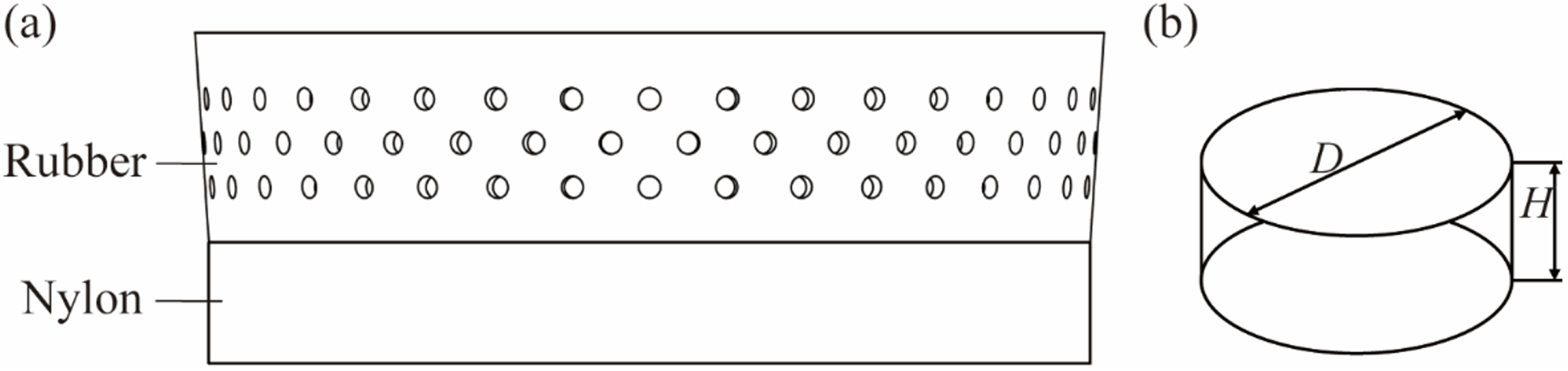
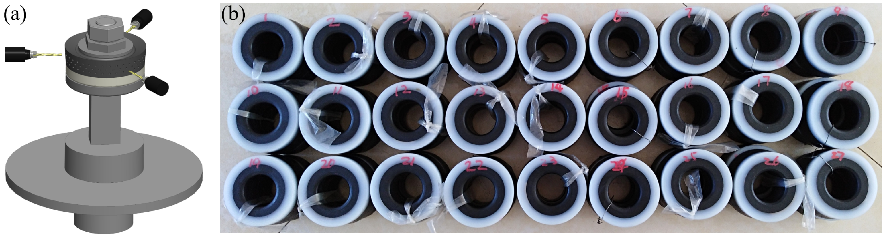
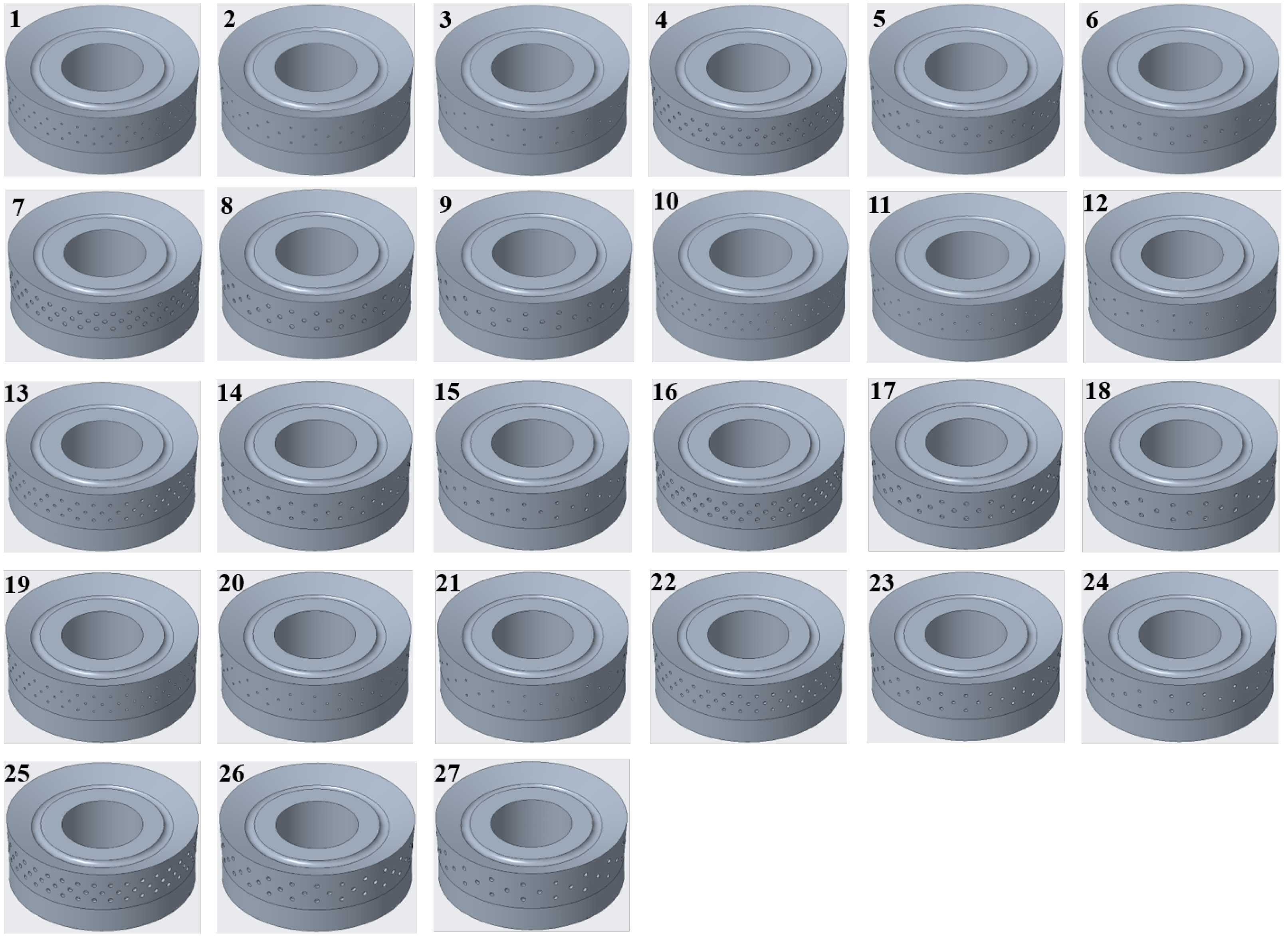
2.1. Piston Design and Test Scheme
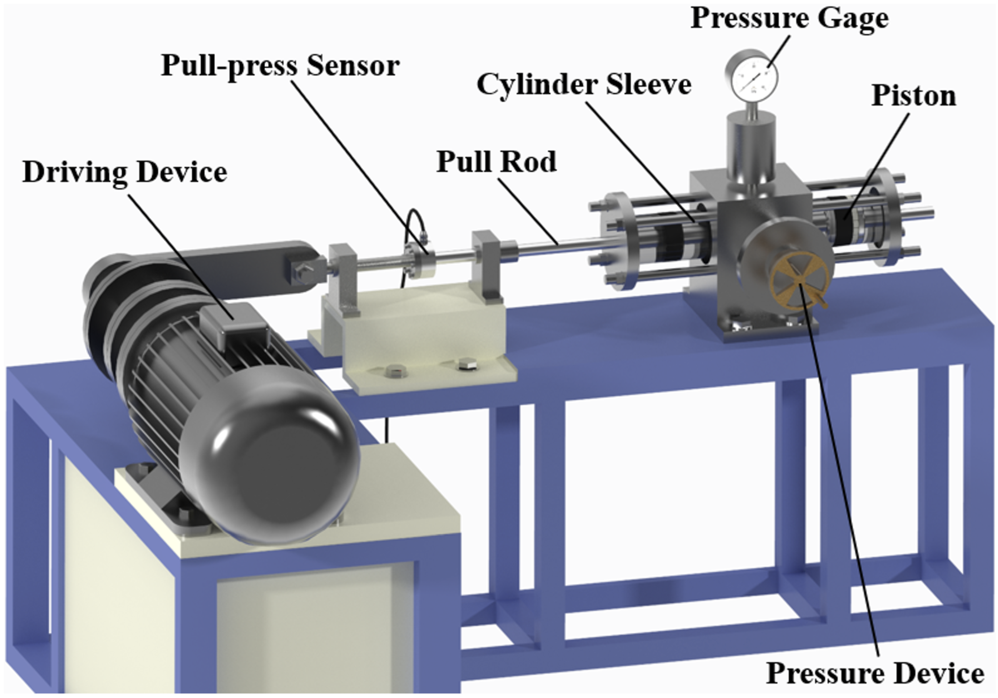
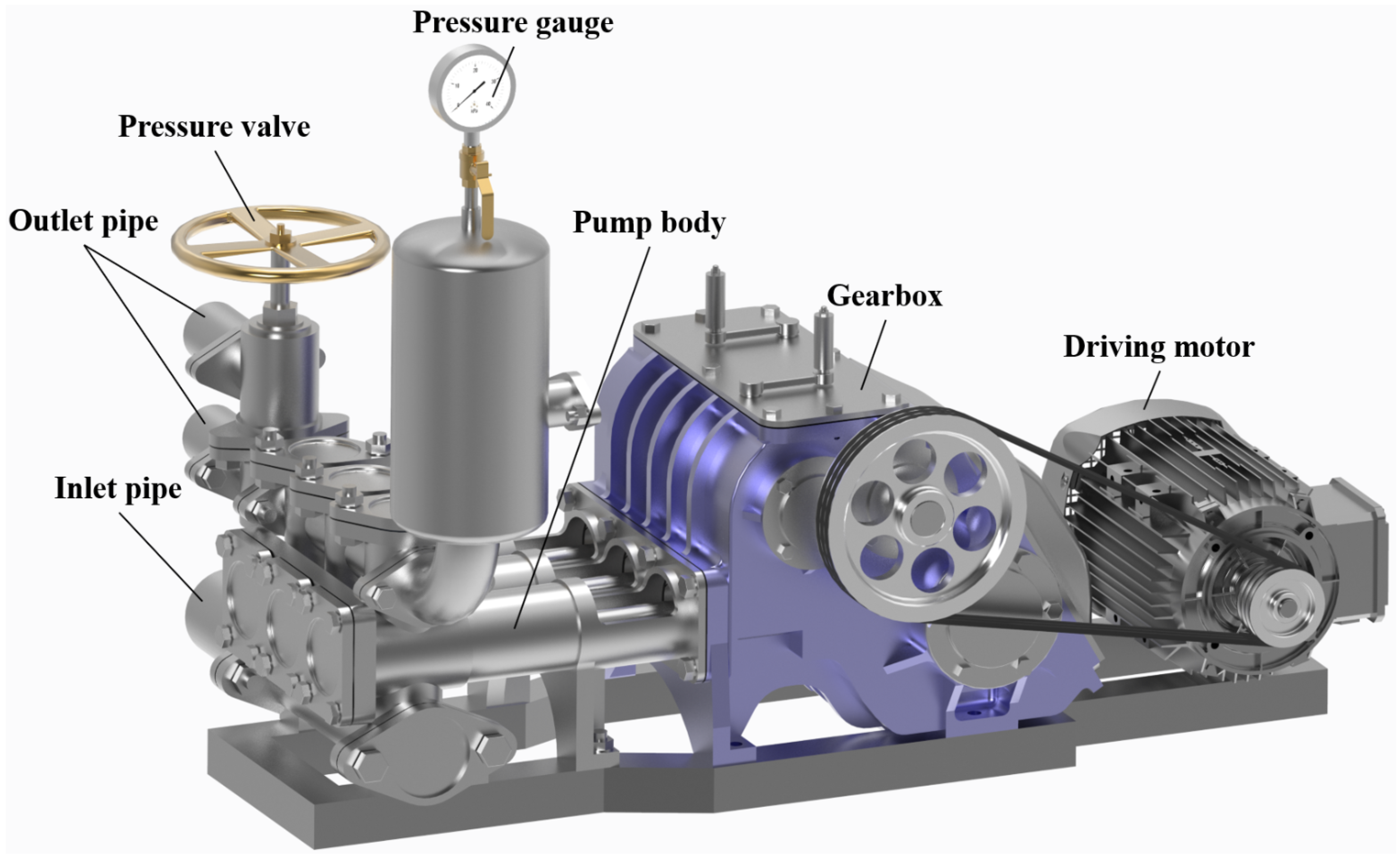
2.2. Test Bench and Test Method
3. Results and Discussion
3.1. Friction Test Results
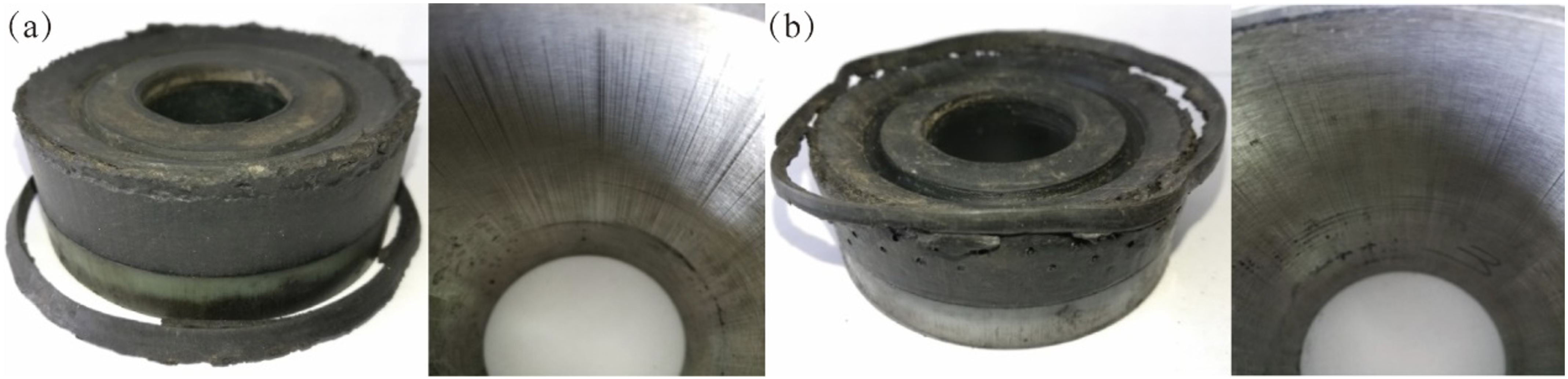
3.2. Wear and Life Test Results
3.3. Thermal Imaging Test Results
4. Friction and Wear Mechanism
5. Conclusions
Author Contributions
Funding
Data Availability Statement
Acknowledgments
Conflicts of Interest
References
- Zhang, J.; Xie, J. Investigation of static and dynamic seal performances of a rubber O-ring. J. Tribol. 2018, 140, 042202. [Google Scholar] [CrossRef]
- Scaraggi, M.; Angerhausen, J.; Dorogin, L.; Murrenhoff, H.; Persson, B. Influence of anisotropic surface roughness on lubricated rubber friction: Extended theory and an application to hydraulic seals. Wear 2018, 410, 43–62. [Google Scholar] [CrossRef]
- Chen, S.H.; Jiang, G.Z.; Li, G.F.; Xie, L.X.; Qian, W.Q. Nonlinear analysis of rotary sealing performance of rubber O-ring. Appl. Mech. Mater. 2014, 470, 371–375. [Google Scholar] [CrossRef]
- Zhou, Z.; Zhou, Q.; Qin, K.; Li, S.; Zhang, K.; Yuan, T.; Sun, W. The particle breakage effect on abrasive wear process of rubber/steel seal pairs under high/low pressure. Polymers 2023, 15, 1857. [Google Scholar] [CrossRef] [PubMed]
- Wu, Y.; Zhou, Y.; Li, J.; Zhou, H.; Chen, J.; Zhao, H. A comparative study on wear behavior and mechanism of styrene butadiene rubber under dry and wet conditions. Wear 2016, 356–357, 1–8. [Google Scholar] [CrossRef]
- Iwai, T.; Uchiyama, Y.; Shimosaka, K.; Takase, K. Study on the formation of periodic ridges on the rubber surface by friction and wear monitoring. Wear 2005, 259, 669–675. [Google Scholar] [CrossRef]
- Hakami, F.; Pramanik, A.; Ridgway, N.; Basak, A. Developments of rubber material wear in conveyer belt system. Tribol. Int. 2017, 111, 148–158. [Google Scholar] [CrossRef]
- Ke, Y.; Yao, X.; Yang, H.; Liu, X. Kinetic friction characterizations of the tubular rubber seals. Tribol. Int. 2014, 72, 35–41. [Google Scholar] [CrossRef]
- Zhou, Y.; Huang, Z.; Bu, Y.; Qiu, C.; Yuan, Y. Simulation studies on drilling mud pump plunger seal failure under ultrahigh pressure and ultradeep conditions. Eng. Fail. Anal. 2014, 45, 142–150. [Google Scholar] [CrossRef]
- Nikas, G.K. Elastohydrodynamics and mechanics of rectangular elastomeric seals for reciprocating piston rods. J. Tribol. 2003, 125, 60–69. [Google Scholar] [CrossRef]
- He, X.; Huang, C.J.; Liu, Q.Y.; Liu, Y.; Tian, J.Y. Finite element analysis of pump casing for triplex plunger pump based on abaqus. Adv. Mater. Res. 2011, 337, 219–224. [Google Scholar] [CrossRef]
- Dong, J.; Deng, Y.; Cao, W.; Wang, Z.; Ma, W.; Wu, D.; Ji, H.; Liu, Y. Wear failure analysis of suction valve for high pressure and large flow water hydraulic plunger pump. Eng. Fail. Anal. 2022, 134, 106095. [Google Scholar] [CrossRef]
- Jia, H.; Zhou, Z.; Yin, B.; Zhou, H.; Xu, B. Effect of compound texture on lubrication and sealing performance of plunger pump. Lubr. Sci. 2021, 33, 43–59. [Google Scholar] [CrossRef]
- Milojević, S.; Savić, S.; Marić, D.; Stopka, O.; Krstić, B.; Stojanović, B. Correlation between Emission and Combustion Characteristics with the Compression Ratio and Fuel Injection Timing in Tribologically Optimized Diesel Engine. Teh. Vjesn. 2022, 29, 1210–1219. [Google Scholar]
- Babu, P. Venkateswara and Syed, Ismail and Benbeera, Satish. Experimental investigation on effects of positive texturing on friction and wear reduction of piston ring/cylinder liner system. Mater. Today Proc. 2020, 24, 1112–1121. [Google Scholar] [CrossRef]
- Kumar, S.; Kumar, M. Tribological and Mechanical Performance of Coatings on Piston to Avoid Failure—A Review. J. Fail. Anal. Prev. 2022, 22, 1346–1369. [Google Scholar] [CrossRef]
- Brazhenko, V.N.; Mochalin, E.V.; Cai, J.-C. Mechanical admixture influence in the working fluid on wear and jamming of spool pairs from aircraft hydraulic drives. J. Frict. Wear 2020, 41, 526–530. [Google Scholar] [CrossRef]
- Etsion, I. State of the art in laser surface texturing. Tribol. Trans. 2005, 127, 248–253. [Google Scholar] [CrossRef]
- Pettersson, U.; Jacobson, S. Influence of surface texture on boundary lubricated sliding contacts. Tribol. Int. 2003, 36, 857–864. [Google Scholar] [CrossRef]
- Yin, H.; Zhang, X.; Guo, Z.; Xu, Y.; Rao, X.; Yuan, C. Synergetic effects of surface textures with modified copper nanoparticles lubricant additives on the tribological properties of cylinder liner-piston ring. Tribol. Int. 2023, 178, 108085. [Google Scholar] [CrossRef]
- Wang, W.; Zhao, W.; Guo, P.; Liu, Q.; Kouediatouka, A.N.; Dong, G. A textured surface with oil inflow and outflow function designed for starved lubrication. Tribol. Int. 2023, 184, 108450. [Google Scholar] [CrossRef]
- Maegawa, S.; Itoigawa, F.; Nakamura, T. Effect of surface grooves on kinetic friction of a rubber slider. Tribol. Int. 2016, 102, 326–332. [Google Scholar] [CrossRef]
- Kumar, S.; Bergada, J.M. The effect of piston grooves performance in an axial piston pumps via CFD analysis. Int. J. Mech. Sci. 2013, 66, 168–179. [Google Scholar] [CrossRef]
- Hu, Y.; Meng, X.; Xie, Y.; Fan, J. Mutual influence of plateau roughness and groove texture of honed surface on frictional performance of piston ring–liner system. Proc. Inst. Mech. Eng. Part J J. Eng. Tribol. 2017, 231, 838–859. [Google Scholar] [CrossRef]
- Gao, T.; Wang, X.; Sun, Y.; Cheng, X.; Cong, Q. Friction and wear performance of bionic stripped piston of BW-160 slime pump. Proc. Inst. Mech. Eng. Part C J. Mech. Eng. Sci. 2020, 234, 872–881. [Google Scholar] [CrossRef]
- Gao, T.; Su, B.; Jiang, L.; Cong, Q. Influence of bionic pit structure on friction and sealing performance of reciprocating plunger. Adv. Mater. Sci. Eng. 2020, 2020, 2130341. [Google Scholar] [CrossRef]
- Guiyue, K.; Xinghu, L.; Yan, W.; Mouyou, L.; Kanran, Z.; Mingfei, M. Parameter study and shape optimisation of a generalised ellipse dimple-textured face seal. Lubr. Sci. 2020, 32, 10–20. [Google Scholar] [CrossRef]
- Liang, Y.; Wang, C.; Wang, W.; Xing, H.; Zhang, Z.; Gao, D. Effect of Composite Bionic Micro-Texture on Bearing Lubrication and Cavitation Characteristics of Slipper Pair. J. Mar. Sci. Eng. 2023, 11, 582. [Google Scholar] [CrossRef]
- Kikuhara, K.; Koeser, P.S.; Tian, T. Effects of a cylinder liner microstructure on lubrication condition of a twin-land oil control ring and a piston skirt of an internal combustion engine. Tribol. Lett. 2022, 70, 1–15. [Google Scholar] [CrossRef]
- Liang, Y.; Gao, D.; Zhao, J. Tribological properties of friction pair between 316L stainless steel and CF/PEEK with nonsmooth surface under seawater lubrication. Tribol. Trans. 2020, 63, 658–671. [Google Scholar] [CrossRef]
- Raeymaekers, B.; Etsion, I.; Talke, F.E. Enhancing tribological performance of the magnetic tape/guide interface by laser surface texturing. Tribol. Lett. 2007, 27, 89–95. [Google Scholar] [CrossRef]
- Brizmer, V.; Kligerman, Y.; Etsion, I. A laser surface textured parallel thrust bearing. Tribol. Trans. 2003, 46, 397–403. [Google Scholar] [CrossRef]
- Kligerman, Y.; Etsion, I.; Shinkarenko, A. Improving tribological performance of piston rings by partial surface texturing. Tribol. Trans. 2005, 127, 632–638. [Google Scholar] [CrossRef]
- Gu, Y.Q.; Dai, D.S.; Mou, J.G.; Zheng, S.H.; Wu, D.H.; Wang, E. Overview of the technology of bionic surface drag reduction. J. Biomimetics Biomater. Biomed. Eng. 2015, 23, 59–66. [Google Scholar] [CrossRef]
- Yu, H.; Deng, H.; Huang, W.; Wang, X. The effect of dimple shapes on friction of parallel surfaces. Proc. Inst. Mech. Eng. Part J J. Eng. Tribol. 2011, 225, 693–703. [Google Scholar] [CrossRef]
- Miladinovic, S.; Sandra, V.; Novakovic, M. Application of Taguchi method for the selection of optimal parameters of planetary driving gear. Appl. Eng. Lett. 2016, 1, 98–104. Available online: https://scidar.kg.ac.rs/handle/123456789/16604 (accessed on 19 October 2023).


| Levels | Factors | ||
|---|---|---|---|
| 1 | 1 | 0.5 | 36 |
| 2 | 1.5 | 1.0 | 24 |
| 3 | 2 | 1.5 | 18 |
| X | H | D | N | X | H | D | N | ||||
|---|---|---|---|---|---|---|---|---|---|---|---|
| 1 | 0.5 | 1.0 | 36 | 121.84 | 152.12 | 15 | 1.0 | 1.5 | 18 | 116.02 | 158.70 |
| 2 | 0.5 | 1.0 | 24 | 158.03 | 184.00 | 16 | 1.0 | 2.0 | 36 | 128.95 | 152.75 |
| 3 | 0.5 | 1.0 | 18 | 141.66 | 212.47 | 17 | 1.0 | 2.0 | 24 | 157.37 | 193.41 |
| 4 | 0.5 | 1.5 | 36 | 105.46 | 119.84 | 18 | 1.0 | 2.0 | 18 | 144.72 | 201.28 |
| 5 | 0.5 | 1.5 | 24 | 134.96 | 187.88 | 19 | 1.5 | 1.0 | 36 | 142.32 | 167.14 |
| 6 | 0.5 | 1.5 | 18 | 119.53 | 185.47 | 20 | 1.5 | 1.0 | 24 | 154.65 | 188.10 |
| 7 | 0.5 | 2.0 | 36 | 146.78 | 162.46 | 21 | 1.5 | 1.0 | 18 | 174.18 | 197.67 |
| 8 | 0.5 | 2.0 | 24 | 122.94 | 174.28 | 22 | 1.5 | 1.5 | 36 | 109.86 | 119.95 |
| 9 | 0.5 | 2.0 | 18 | 145.29 | 215.25 | 23 | 1.5 | 1.5 | 24 | 161.89 | 184.65 |
| 10 | 1.0 | 1.0 | 36 | 111.34 | 137.58 | 24 | 1.5 | 1.5 | 18 | 171.79 | 213.73 |
| 11 | 1.0 | 1.0 | 24 | 175.99 | 215.31 | 25 | 1.5 | 2.0 | 36 | 116.40 | 130.25 |
| 12 | 1.0 | 1.0 | 18 | 151.56 | 215.28 | 26 | 1.5 | 2.0 | 24 | 162.17 | 202.77 |
| 13 | 1.0 | 1.5 | 36 | 111.02 | 117.76 | 27 | 1.5 | 2.0 | 18 | 149.03 | 192.84 |
| 14 | 1.0 | 1.5 | 24 | 155.62 | 174.00 | S | 0 | 0 | 0 | 196.22 | 251.16 |
| D () | H () | N | |||||||
|---|---|---|---|---|---|---|---|---|---|
| 1.0 | 1.5 | 2.0 | 0.5 | 1.0 | 1.5 | 36 | 24 | 18 | |
| 147.95 | 131.79 | 141.52 | 132.94 | 139.18 | 149.14 | 121.55 | 153.74 | 145.97 | |
| 185.52 | 162.44 | 180.59 | 177.09 | 174.01 | 177.46 | 139.98 | 189.38 | 199.19 | |
| Y | (g) | (g) | m (g) | w | L () | v |
|---|---|---|---|---|---|---|
| S-1 | 140.96 | 134.42 | 6.54 | 4.64% | 1139 | |
| 4 | 140.65 | 137.86 | 2.79 | 1.98% | 1648 | 44.69% |
| 13 | 139.17 | 136.60 | 2.57 | 1.84% | 1519 | 33.36% |
| S-2 | 144.82 | 139.51 | 5.31 | 3.66% | 1161 | |
| 22 | 144.56 | 141.98 | 2.58 | 1.78% | 1721 | 48.23% |
| 25 | 143.62 | 138.72 | 4.90 | 3.41% | 1333 | 14.81% |
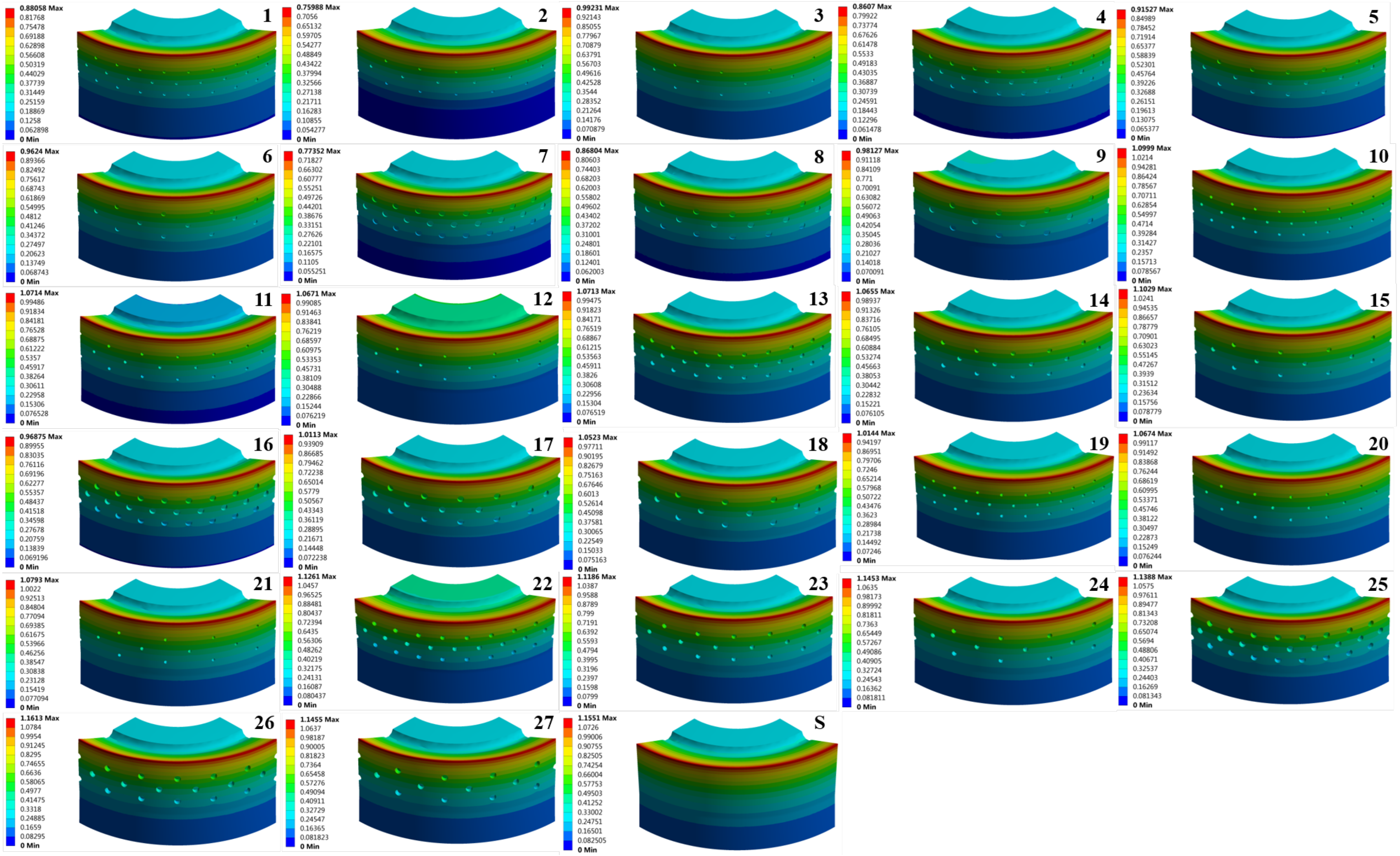
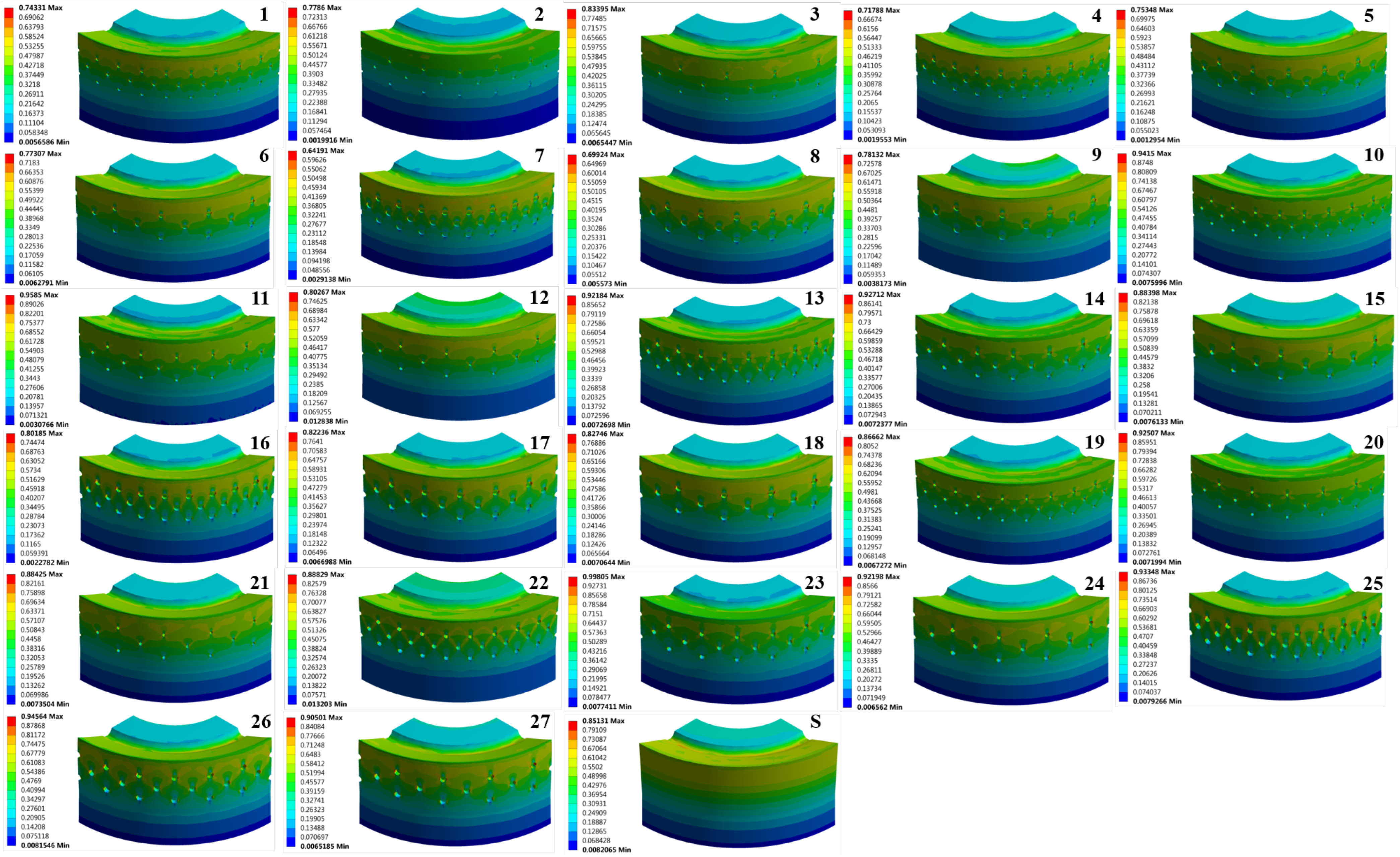
| Y | S | 4 | 13 | 22 | 25 |
|---|---|---|---|---|---|
| () | 1.1701 | 0.8607 | 1.0713 | 1.1261 | 1.1388 |
| () | 0.85131 | 0.71788 | 0.92184 | 0.88829 | 0.93348 |
Disclaimer/Publisher’s Note: The statements, opinions and data contained in all publications are solely those of the individual author(s) and contributor(s) and not of MDPI and/or the editor(s). MDPI and/or the editor(s) disclaim responsibility for any injury to people or property resulting from any ideas, methods, instructions or products referred to in the content. |
© 2023 by the authors. Licensee MDPI, Basel, Switzerland. This article is an open access article distributed under the terms and conditions of the Creative Commons Attribution (CC BY) license (https://creativecommons.org/licenses/by/4.0/).
Share and Cite
Gao, T.; Chen, H.; Tang, D.; Wang, Y. Inspired by Earthworms and Leeches: The Effects of Cylindrical Pit Arrays on the Performance of Piston-Cylinder Liner Friction Pairs. Appl. Sci. 2023, 13, 11580. https://doi.org/10.3390/app132011580
Gao T, Chen H, Tang D, Wang Y. Inspired by Earthworms and Leeches: The Effects of Cylindrical Pit Arrays on the Performance of Piston-Cylinder Liner Friction Pairs. Applied Sciences. 2023; 13(20):11580. https://doi.org/10.3390/app132011580
Chicago/Turabian StyleGao, Tianyu, Hao Chen, Danna Tang, and Yumo Wang. 2023. "Inspired by Earthworms and Leeches: The Effects of Cylindrical Pit Arrays on the Performance of Piston-Cylinder Liner Friction Pairs" Applied Sciences 13, no. 20: 11580. https://doi.org/10.3390/app132011580
APA StyleGao, T., Chen, H., Tang, D., & Wang, Y. (2023). Inspired by Earthworms and Leeches: The Effects of Cylindrical Pit Arrays on the Performance of Piston-Cylinder Liner Friction Pairs. Applied Sciences, 13(20), 11580. https://doi.org/10.3390/app132011580