Article

Design and Optimization of a Toothed-Plate Single-Roller Crushing Device for Waste Plastic Film

1
Nanjing Institute of Agricultural Mechanization, Ministry of Agriculture and Rural Affairs, Nanjing 210014, China
2
Graduate School of Chinese Academy of Agricultural Sciences, Beijing 100081, China
*
Authors to whom correspondence should be addressed.
Appl. Sci. 2023, 13(21), 11650; https://doi.org/10.3390/app132111650
Submission received: 9 October 2023 / Revised: 18 October 2023 / Accepted: 23 October 2023 / Published: 25 October 2023
(This article belongs to the Special Issue Reducing the Plastic Footprint of Agriculture)

Abstract

:
Waste plastic film often contains an abundance of impurities, such as crop stems and soil. To address this issue, a toothed-plate single-roller crushing device for waste plastic film was developed. By analyzing the movement and force pattern of the film, the feeding speed, the number of toothed plates, and the crushing roller rotation speed were used as test factors, and the size qualification rate and the impurity content of the crushed film were used as test indexes. Through a Box–Behnken test design, regression analysis, and ANOVA, a model between factors and indexes was established. The results showed that the size qualification rate and the impurity content of the crushed film were 82.55% and 9.57%, and the errors in the prediction and test values were 6.14% and 8.38%, which proved them to have good reliability. The findings of this study provide essential technical and equipment support for the resource recovery of waste plastic films.

1. Introduction

Using mulch film can effectively reduce water loss and enhance crop water utilization rates [1,2]. It can prevent rainwater from eroding and impacting crops while maintaining soil moisture and temperature [3]. Moreover, mulch film is cost-effective and user-friendly, making it particularly popular in cold and arid regions. Its usage not only increases crop yields but also mitigates soil erosion [4,5,6].
Since the introduction of mulch film technology in China in 1979, the usage of mulch film has steadily increased, growing from 6000 tons in 1981 [7] to 1,320,000 tons in 2021 [8] among the regions of China. However, there is a lack of awareness among farmers regarding mulch film recycling, with a recycling rate of less than 60% [9], which has resulted in a growing issue of mulch film residue pollution [10]. In recent years, a large number of recovery machines have been utilized to address the pollution issue. However, a significant issue persists: the waste plastic film collected by the machinery contains impurities, such as crop stalks and soil, which hinders its resource utilization [11,12]. Therefore, mechanized preliminary cleaning, such as crushing, has become a critical step in the resource utilization of waste plastic film [13].
In the research on single-roller crushing technology, numerous scholars have conducted multifaceted explorations. Tuck [14] conducted a comparison between disc-type and roller-type cutting blades, and the results of optimization experiments indicated that the minimum cutting length was achieved at a forward speed of 9 km/h with a tooth spacing ranging from 8 to 10 mm. Zhong Hongyan [15] researched a crushing machine for plastic film, and the findings demonstrated that employing a supported high-speed rotating blade roller to crush highly strained plastic films yielded better results. Liao Peiwang [16] designed a roller-type cotton-stalk shredder mechanism, Through the coordinated action of crushing plates and cutting blades, cotton stalks are first crushed and then chopped, thereby enhancing the fragmentation efficiency for hard materials. Zheng Zhiqi found that when the crushing roller rotation speed exceeded 1600 r/min, the supported crushing method achieved a crushing length qualification rate exceeding 90%. Moreover, it resulted in a 17.4% reduction in power consumption compared to the unsupported crushing method. Li Li [17] researched the cutting blade angle of the rubber crusher. They utilized ANSYS to analyze various blade angles for crushing tools. Simulation experiments demonstrated that a cutting blade angle of 42° yielded the optimal comprehensive performance. These machines of previous research are effective in crushing hard materials. However, when they are used for the crushing of waste plastic film with the property of high ductility [18], clogging of the crushing components is likely to result because flexible materials often require sharp cutting blades that utilize tearing forces to crush them. For hard materials, the use of sharp cutting blades can reduce their lifespan, and blunt blades are typically used to crush hard materials [19,20]. There is currently limited research on the co-crushing of flexible and hard materials. Therefore, it is necessary that such research be undertaken for advancement in the field of crushing technology for waste plastic film, as it will increase the efficiency of its resource utilization.
In this study, based on previous experimental determinations of the mechanical properties of waste plastic film and crop stalks [21], we have designed a toothed-plate single-roller crushing device for waste plastic film. By coordinating the action of the moving toothed plate and the fixed toothed plate, waste plastic film and crop stalks are first crushed and then torn apart, thus achieving their co-crushing. Following previous research and recycling industry requirements, the crushed film area ranges from 1000 mm2 to 6000 mm2, which is conducive to the cleaning and separation of the crushed waste plastic film [22,23]. Moreover, achieving a low impurity content in the waste plastic film after preliminary cleaning can enhance the quality of waste plastic film recycling. Through kinematic and mechanical analyses of the crushing process, factors influencing the crushed film size and impurity content have been identified, including the feeding velocity, the number of toothed plates, and the crushing roller rotation speed. We used feeding velocity, the number of toothed plates, and the crushing roller rotation speed as test factors and the size qualification rate and the impurity content of crushed film as optimization indexes; a Box–Behnken three-factor, three-level experiment was designed. Finally, through response surface analysis, we determined the relationships between the three factors and the optimization indexes, leading to the identification of the optimal combination of factor parameters. This research introduced an innovative approach to the design and optimization of a crushing device for waste plastic film. The research results can provide crucial technical and equipment support for the resource utilization of waste plastic film.

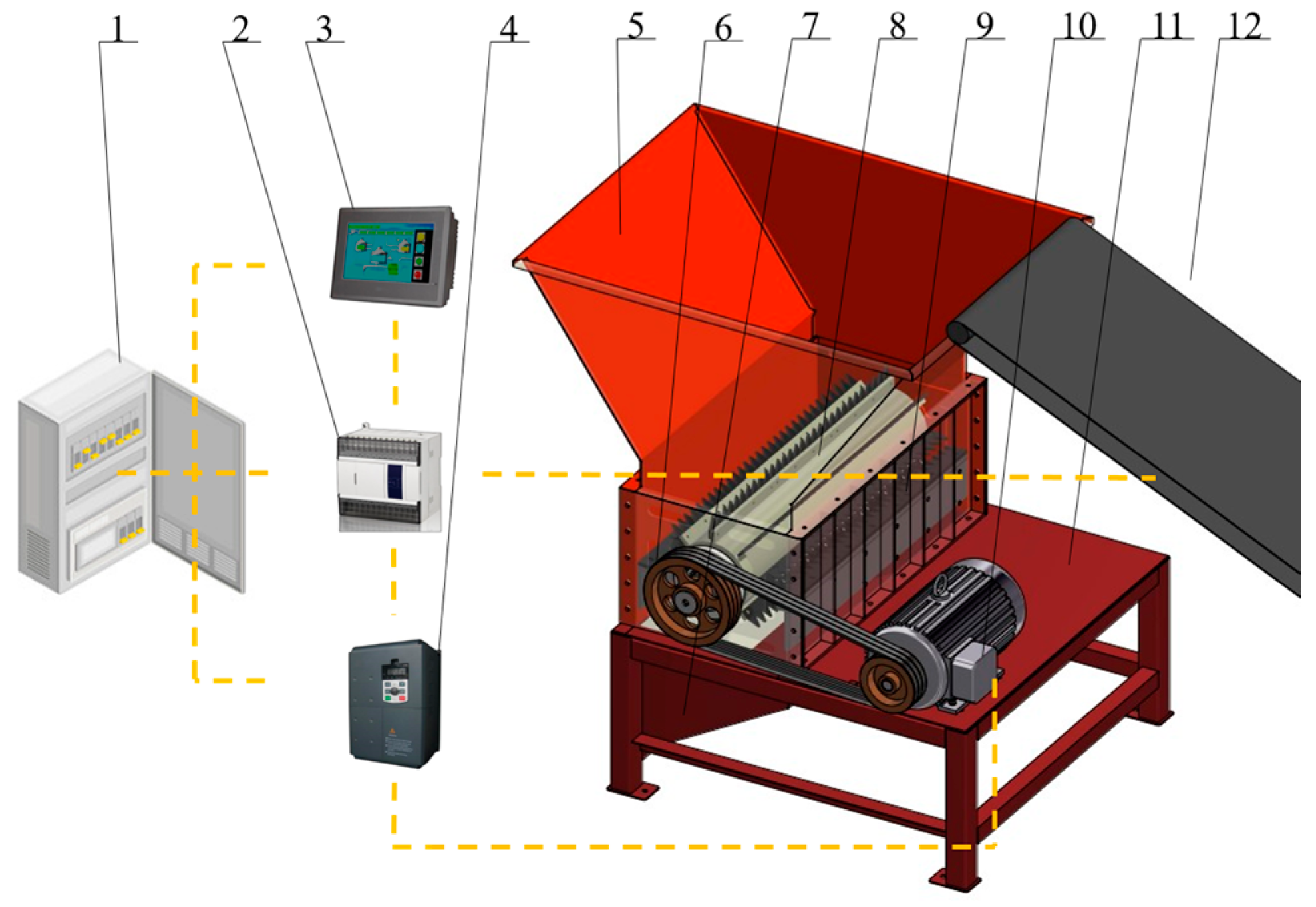
2. The Structure and Principles of the Crushing Device

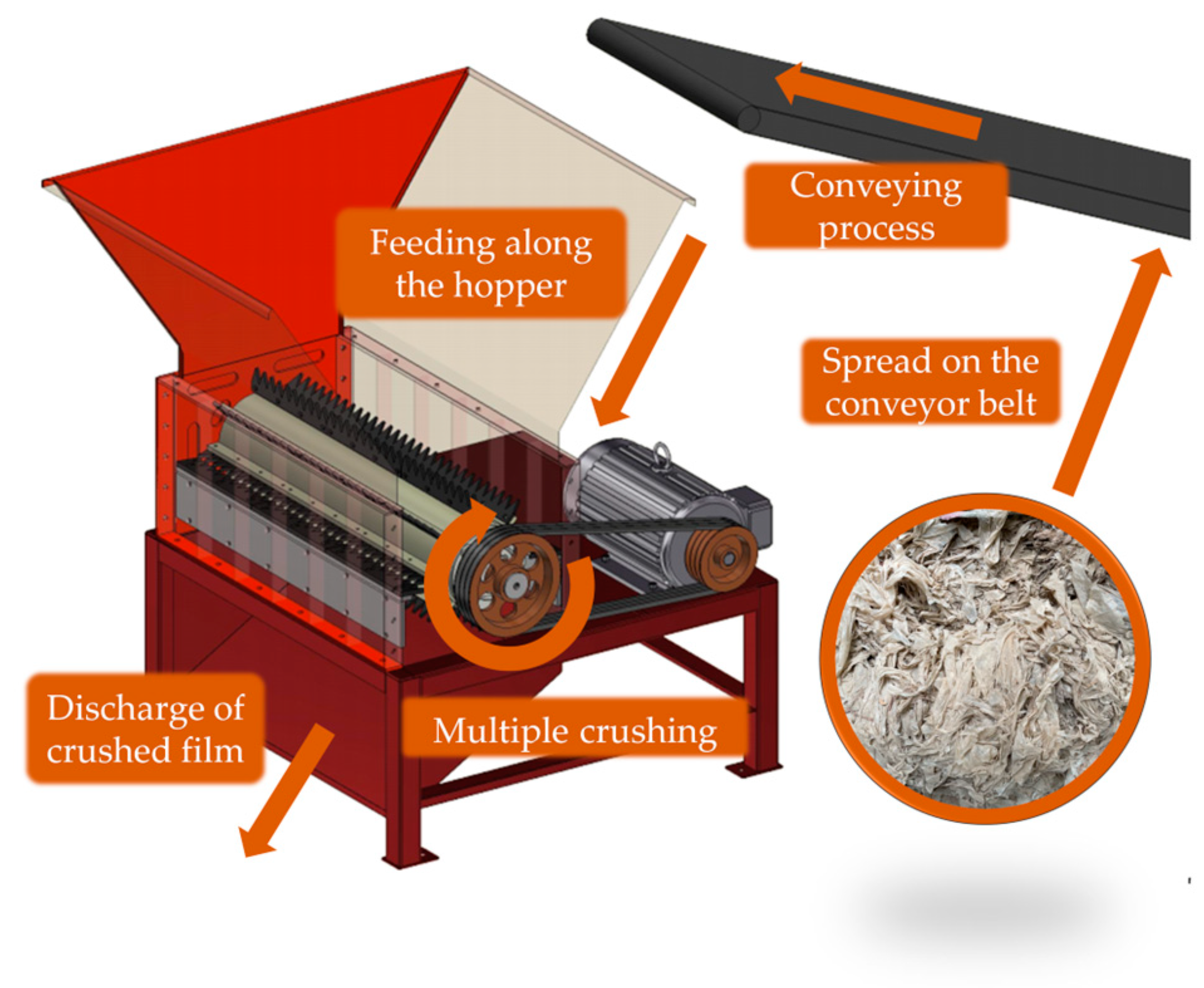
2.1. Structure of the Crushing Device

As shown in Figure 1, the primary components of the toothed-plate single-roller crushing device include a crushing component, an electrical control component, a conveyor component, a transmission component, a frame, a feeding hopper, and a discharge hopper. Within the crushing component, there are 8 toothed-plate holders uniformly welded on the outer circumference of the crushing roller. Each holder can accommodate 3 moving toothed plates, and their arrangement and quantity can be adjusted according to specific crushing requirements. The conveying component has an adjustable speed and a width of 0.8 m and is capable of meeting the needs of waste plastic film transport. The electrical control component consists of a touchscreen, a programmable controller, and a frequency converter, enabling functions such as whole-machine control and overload protection.

2.2. Principles of Crushing Working

The toothed-plate single-roller crushing device is controlled by electrical control components and driven by a motor. During operation, the motor transmits power through the V-belt and gradually increases the rotation speed of the crushing roller. After the rotation speed stabilizes, the conveyor belt starts at the set speed and begins continuous feeding. Subsequently, the waste plastic film enters the feeding hopper and falls into the crushing component along the inclined plate of the hopper. Then, the moving toothed plate and the fixed toothed plate work together, compressing, cutting, and tearing the waste plastic film in the crushing box. After the first crushing, smaller pieces of waste plastic film are expelled from the discharge hopper by the airflow, while larger pieces are taken by the crushing roller and undergo secondary crushing on the opposite side. Through multiple crushing, the waste plastic film pieces are consistently expelled from the discharge hopper at a stable velocity. When the feeding volume becomes excessive, the motor will stop working under the control of the electrical control system, and the conveyor belt will also stop feeding. Then, the motor undergoes a reverse clearing process according to a predefined control program. Once the blockage is cleared, the motor will return to working mode, and the conveyor belt will resume feeding.

3. Design and Theoretical Analysis of the Crushing Component

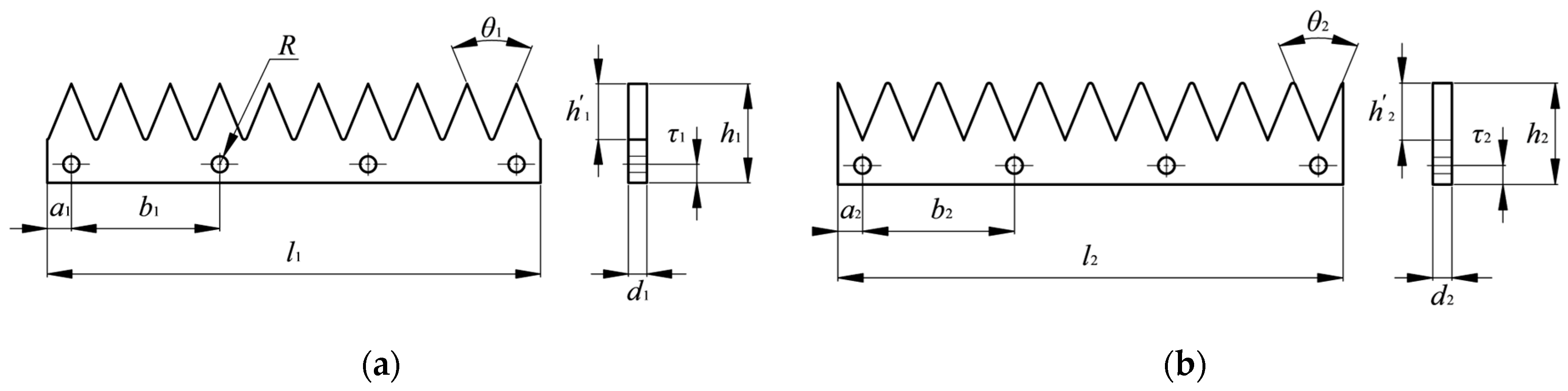
3.1. Design of the Crushing Toothed Plate

Considering the mechanical properties, structural features, and failure conditions of waste plastic film and crop stalks, the triangular-sectioned toothed plate has been designed. The structures of the moving toothed plate and the fixed toothed plate are illustrated in Figure 2a,b. The two work in coordination, exerting a compressing, cutting, and tearing effect on waste plastic film.
The cutting-edge angles, θ1 and θ2, have a major impact on the toothed-plate strength and crushing performance. When θ1 and θ2 are too large, the toothed plate has high strength and a long service life, but the crushing performance is poor. When θ1 and θ2 are too small, the crushing performance is good, but the strength of the toothed plate is poor. Referring to the crushing of soybean stalks [24], 45° is considered the optimal process parameter for the cutting edges (θ1 and θ2). Considering the cleaning process of waste plastic film, referring to the existing washing and suspension separation equipment [22,23,25], the tooth heights, h1 and h2, were designed to be 45 mm. According to the mechanical design standard, the hole diameter, R, was selected as 13 mm, and the fixed hole margins, a1, τ1, a2, and τ2, should not be less than 10.3 mm. Thus, the design of a1 and a2 was 20 mm, and τ1 and τ2 were 15 mm. The length of the moving and fixed toothed plates was 400 mm and the number of fixed holes was 4, and a calculation showed that the hole spacings, b1 and b2, were 120 mm.

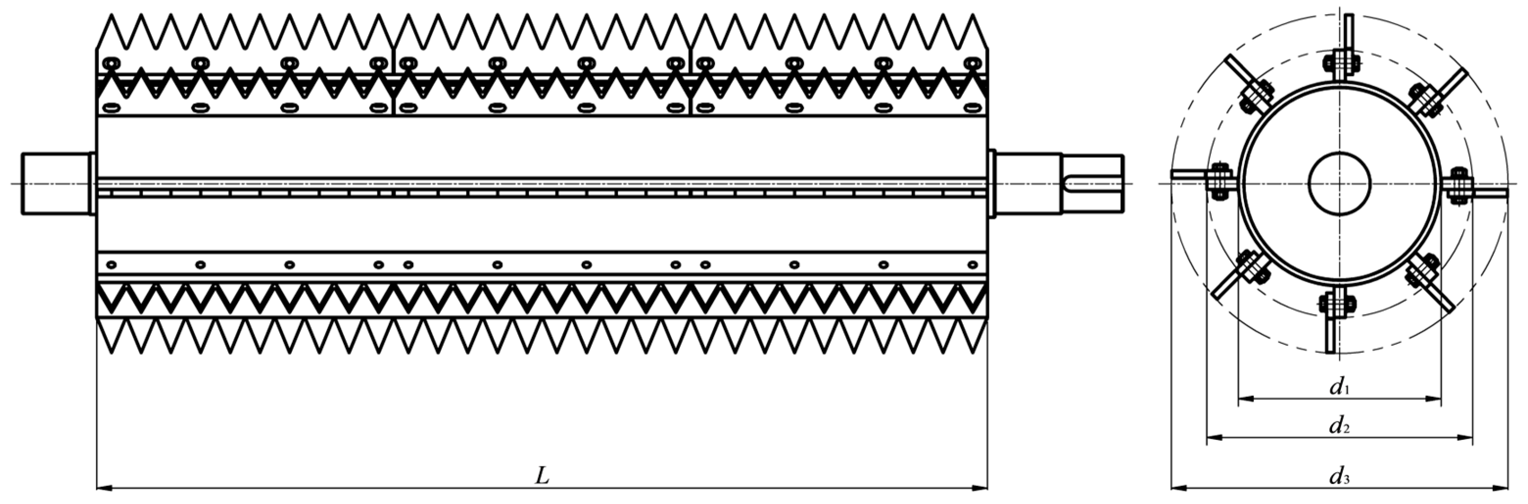
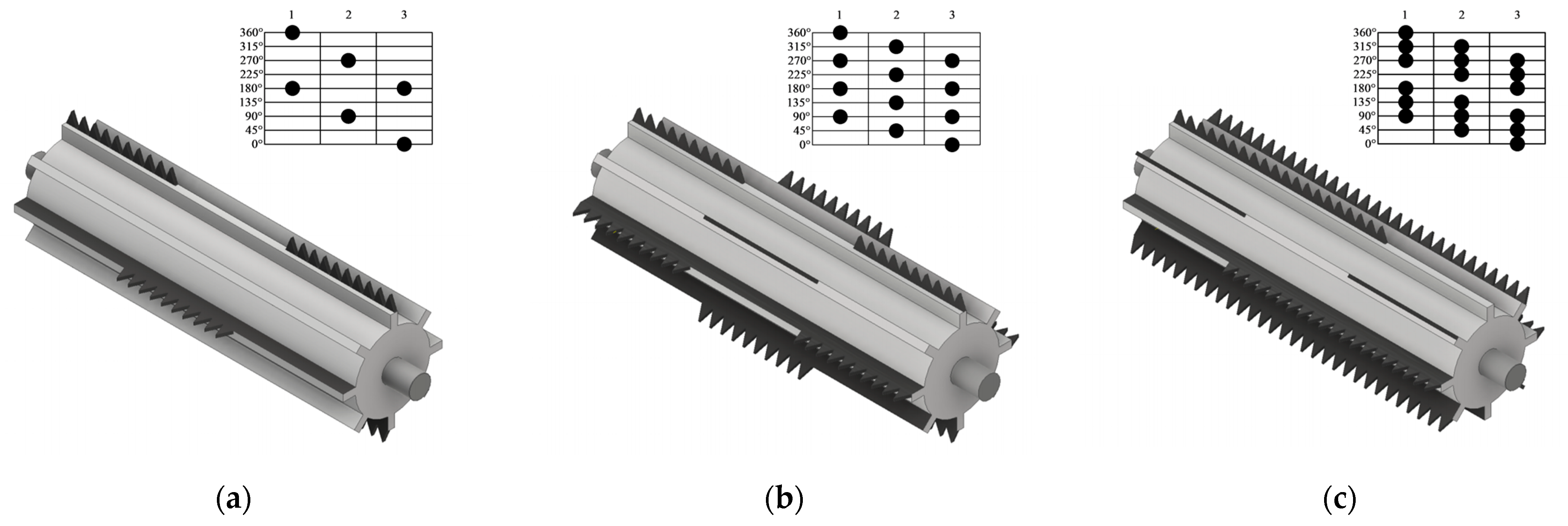
3.2. Design of the Crushing Roller

Referring to the relevant rotation crushing device [26,27], the design of the crushing roller structure is shown in Figure 3. For single-roller plastic-crushing devices, the crushing roller outer diameter is generally not greater than 500 mm. Therefore, the diameter of the tooth tip circle, d3, and the roller diameter, d1, were determined to be 450 mm and 280 mm. Based on a tooth height of 45 mm, it was calculated that the diameter of the toothed bottom circle of the crushing roller, d2, is 360 mm. The length of the toothed plate was 400 mm, and three of them were installed along the axial direction of the crushing roller, resulting in the minimum length of the crushing roller L being 1200 mm.
The crushing roller rotation speed should be determined by the crushing principle and material characteristics; for the rotation crushing roller with a fixed toothed plate, the rotation speed can be appropriately reduced. Referring to crop stalk crushing [28], the linear speed of the crushing roller teeth was 6 m/s~16 m/s, which was more effective. Combined with the high ductility characteristics of waste plastic film, the linear speed of the crushing roller teeth, V ω , was designed at 14 m/s. The theoretical rotation speed of the crushing roller was calculated to be 594 r/min according to Equation (1). Regarding the new plastic-crushing device [29], the maximum speed is set at 900 r/min. Thus, taking into account the problem of rotation speed adjustment in the subsequent test, the rotation speed range of the crushing roller was determined to be from 600 r/min to 900 r/min.
ω = 60 V ω π d 3
where ω is the crushing roller rotation speed, r/min; V ω is the linear speed of the crushing roller toothed tip, m/s; and d 3 is the diameter of the toothed tip circle, m.
The number of toothed plates has a great influence on the working stability and crushing performance of the crushing device. At the same rotation speed, there is an optimum value for the number of toothed plates. When there are too few toothed plates, productivity is low, and the number of crushing times by one rotation of the crushing roller also decreases, leading to the problem of waste plastic film being incompletely crushed or oversized crushed film, which enhances the difficulty of cleaning. Conversely, when there are too many toothed plates, the crushed film size is excessively small, making it difficult to collect and separate. Additionally, having too many toothed plates can impede the timely discharge of crushed film, increasing the possibility of blockages. At present, the toothed plates on the crushing roller are mainly arranged in a spiral pattern, which has a simple structure and a better crushing performance for the material. Thus, three types of crushing rollers were designed, as shown in Figure 4. The toothed plates of the three types were all arranged in a spiral pattern, with the number of toothed plates being the distinguishing factor. Figure 4a–c represent the crushing roller with 6, 12, and 18 toothed plates, referred to as T1-, T2-, and T3-type crushing rollers, respectively.

3.3. Crushing Roller Vibration Frequency Analysis

The rotating crushing roller is prone to vibration, and these vibrations will cause fatigue damage to the crushing components, affecting the service life and even causing accidents. Therefore, ANSYS was used to perform modal analysis on the T1, T2, and T3 crushing rollers to analyze their excitation frequencies and maximum deformation. The numerical simulation results are shown in Figure 5 and Table 1.
From Figure 5, it can be observed that in the first five modes, the locations of maximum deformation are similar for all three types. However, in mode 6, the T3 crushing roller exhibits maximum deformation mainly on both sides, while the T1 and T2 crushing rollers show maximum deformation mainly in the middle. Table 1 shows that the minimum excitation frequency of the T1, T2, and T3 crushing rollers in the first six orders are 401.71 Hz, 400.73 Hz, and 400.75 Hz, respectively, and the maximum deformation values are 2.89 mm, 2.86 mm, and 4.12 mm, respectively. Through calculations using Formula (2), it can be determined that the minimum excitation rotation speeds for the T1, T2, and T3 crushing rollers are 24,103 r/min, 24,044 r/min, and 24,045 r/min, which are far greater than the design maximum rotation speed of 900 r/min. Therefore, all three types of crushing rollers are not expected to generate severe vibrations during operation.
ω e = 60 f e
where ω e is the excitation rotation speed of the crushing roller, r/min, and f e is the excitation frequency of the crushing roller, Hz.

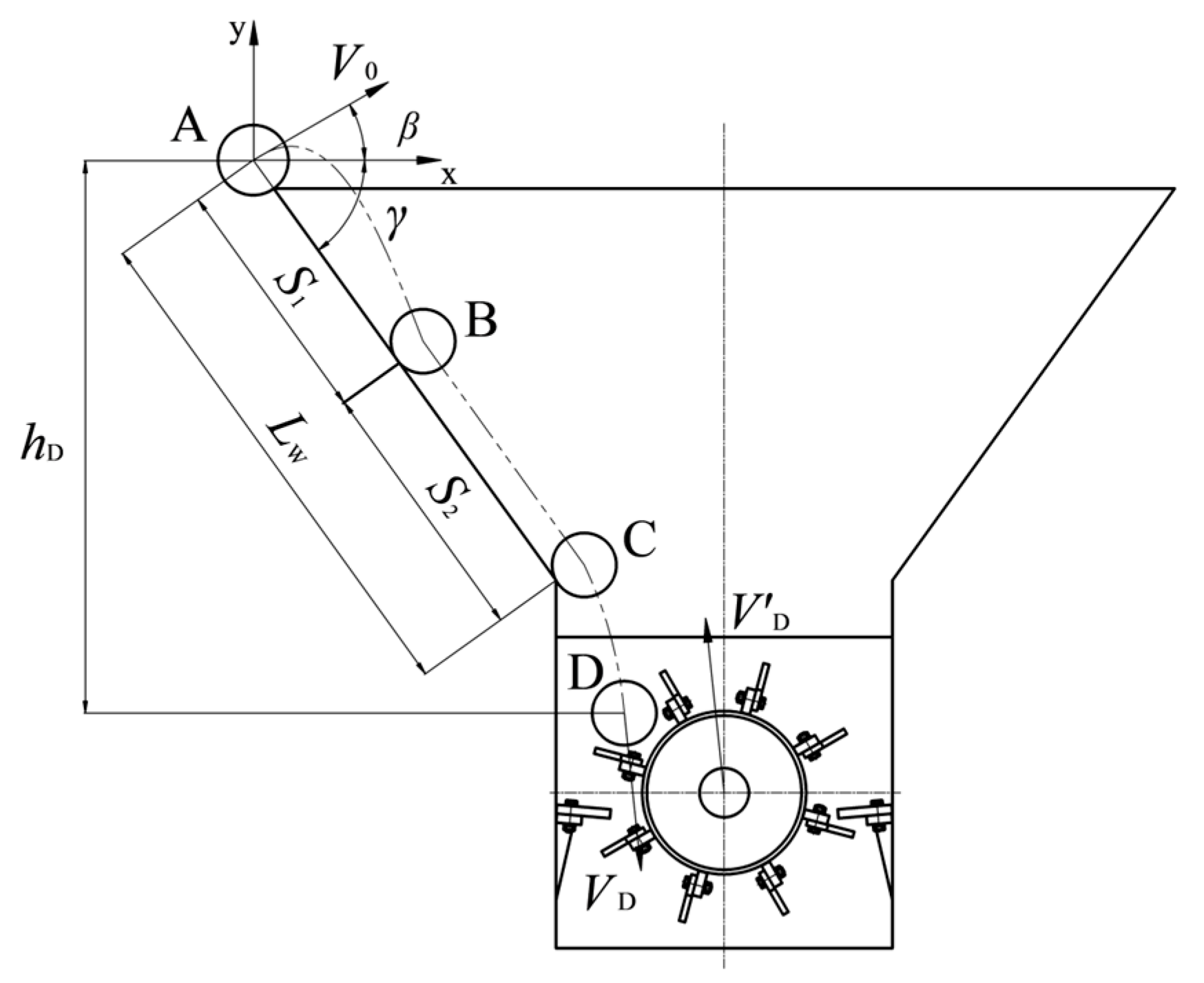
3.4. The Analysis of the Movement and Force Pattern

To investigate the relationship between the crushed film size and the crushing device parameters, it is necessary to analyze the movement characteristics during the feeding process, as shown in Figure 6. The waste plastic film is initially fed from point A with an initial velocity, V D , and the direction of feeding is the angle of the conveyor belt installation, β. After that, the waste plastic film enters the feeding hopper and falls to point B, then contacts with the hopper side plate for a distance of S2 and is thrown downward from point C at an angle γ with the horizontal direction. At last, the waste plastic film falls to point D, which is at a vertical distance, hD, from point A, with a velocity of V D .
Taking point D as the reference point, the motion of the crushing roller can be decomposed into translation and self-rotation. The translational velocity is V D , whose value is the same as V D and whose direction is opposite. In this case, the trajectory of the crushing roller tooth tip can be viewed as a trochoid. The theoretical crushing thickness of the waste plastic film can be expressed as:
l m = 2 π V D Z ω
where l m is the theoretical crushing thickness, mm; V D is the relative velocity of the crushing roller, m/s; Z is the number of crushing roller toothed plates; and ω is the crushing roller rotation speed, r/min.
{ y = x tan β g x 2 2 V 0 2 ( 1 + tan 2 β ) y = x tan γ S 1 = y B sin γ S 2 = L w S 1 1 2 m 1 V 0 2 1 2 m 1 V 0 2 = m 1 g h D μ 1 m 1 gcos γ S 2
where β is the angle between the feeding velocity and the x-axis, °; V 0 is the feeding velocity, m/s; γ is the angle between the hopper side plate and the x-axis, °; S 1 is the non-contact distance, m; S 2 is the contact distance, m; L w is the total length of the feeding hopper side plate, m; m 1 is the feeding mass, kg; h D is the vertical distance between point D and point A, m; and μ 1 is the friction coefficient between the waste plastic film and the feeding hopper side plate.
Combining Equations (3) and (4), we can derive the theoretical crushing thickness, l m , as follows:
l m = 2 π Z ω V 0 2 + 4 μ 1 V 0 2 cos 2 β ( tan γ + tan β ) + 2 g h D 2 μ 1 g L w cos γ
where l m is the theoretical crushing thickness, mm; Z is the number of crushing roller toothed plates; ω is the crushing roller rotation speed, r/min; β is the angle between the feeding velocity and the x-axis, °; V 0 is the feeding velocity, m/s; γ is the angle between the hopper side plate and the x-axis, °; L w is the total length of the feeding hopper side plate, m; h D is the vertical distance between point D and point A, m; and μ 1 is the friction coefficient between the waste plastic film and the feeding hopper side plate.
The value of the crushing thickness directly affects the size of the crushed film. From Equation (5), it can be observed that V 0 , Z , and ω can alter the crushing thickness, thereby influencing the size of the crushed film. Therefore, it is necessary to find the optimal feeding velocity, number of toothed plates, and crushing roller rotation speed to achieve the goal of obtaining the optimal size for subsequent cleaning and separation.
The mechanical analysis of the crushing process is conducted as illustrated in Figure 7. The crushing device primarily relies on the cooperation between the moving toothed plates and the fixed toothed plates to achieve the compressing, cutting, and tearing of waste plastic film. After the initial crushing in the left-side area of Figure 6, the waste plastic film is taken by the moving toothed plates and undergoes a second round of crushing in the right-side crushing area.
The value of the force, F q 1 , has a great impact on the impurity content of the crushed film. When F q 1 is large, for the same amount of time, the impulse of the toothed plates on the waste plastic film is greater, which means a larger increment in the overall momentum, leading to a larger velocity increment for both soil impurities and film. Furthermore, according to the principle of the conservation of momentum, the ratio of the velocity increment for soil impurities and film is constant. A larger velocity increment for soil impurities and film will result in a greater difference in their velocities, thereby achieving separation between soil impurities and film. Since the force principles are the same on both sides, only the mechanical equation for the first crushing process is listed, as shown in Equation (6).
{ F n 1 sin α 1 + f a 1 cos α 1 = f b 1 cos ( η 1 + ω t ) + F q 1 sin ( η 1 + ω t ) + m 1 g F n 1 cos α 1 + f b 1 sin ( η 1 + ω t ) = f a 1 sin α 1 + F q 1 cos ( η 1 + ω t ) f a 1 = μ 2 F n 1 f b 1 = μ 3 F q 1
where F n 1 is the support force of the fixed toothed plate on the materials, N; α 1 is the angle between the fixed toothed plate and the side plate, °; f a 1 is the frictional force between the materials and the fixed toothed plate, N; f b 1 is the frictional force between the materials and the moving toothed plate, N; F q 1 is the crushing force of the moving toothed plate on the materials, N; η 1 is the angle between the moving toothed plate and the side plate, °; m 1 is the mass of materials crushed by a single toothed plate, kg; μ 2 is the friction coefficient between the fixed toothed plate and the materials; and μ 3 is the friction coefficient between the moving toothed plate and the materials.
μ 2 and μ 3 are the friction coefficients between the toothed plates and the materials, which can be approximated as equal. Combining the various terms in Equation (6), the expression for the crushing force, F q 1 , can be derived.
F q 1   = m 1 g ( cos α 1 μ 2 sin α 1 ) ( 1 μ 2 2 ) sin ( α 1 + η 1 + ω t )
where F q 1 is the crushing force of the moving toothed plate on the materials, N; α 1 is the angle between the fixed toothed plate and the side plate, °; η 1 is the angle between the moving toothed plate and the side plate, °; m 1 is the mass of materials crushed by a single toothed plate, kg; μ 2 is the friction coefficient between the fixed toothed plate and the materials; and ω is the crushing roller rotation speed, r/min.
From Equation (7), it can be observed that the value of F q 1 is a function of ω and m 1 . ω can be directly adjusted, while m 1 cannot be directly adjusted. To adjust m 1 , it is necessary to change the feeding velocity, V 0 , and the number of toothed plates, Z . Based on the above analysis, F q 1 is related to the crushed film impurity content, demonstrating that the impurity content is greatly associated with the feeding velocity, V 0 ; the roller rotation speed, ω ; and the number of toothed plates, Z .

4. Materials and Methods of the Crushing Test

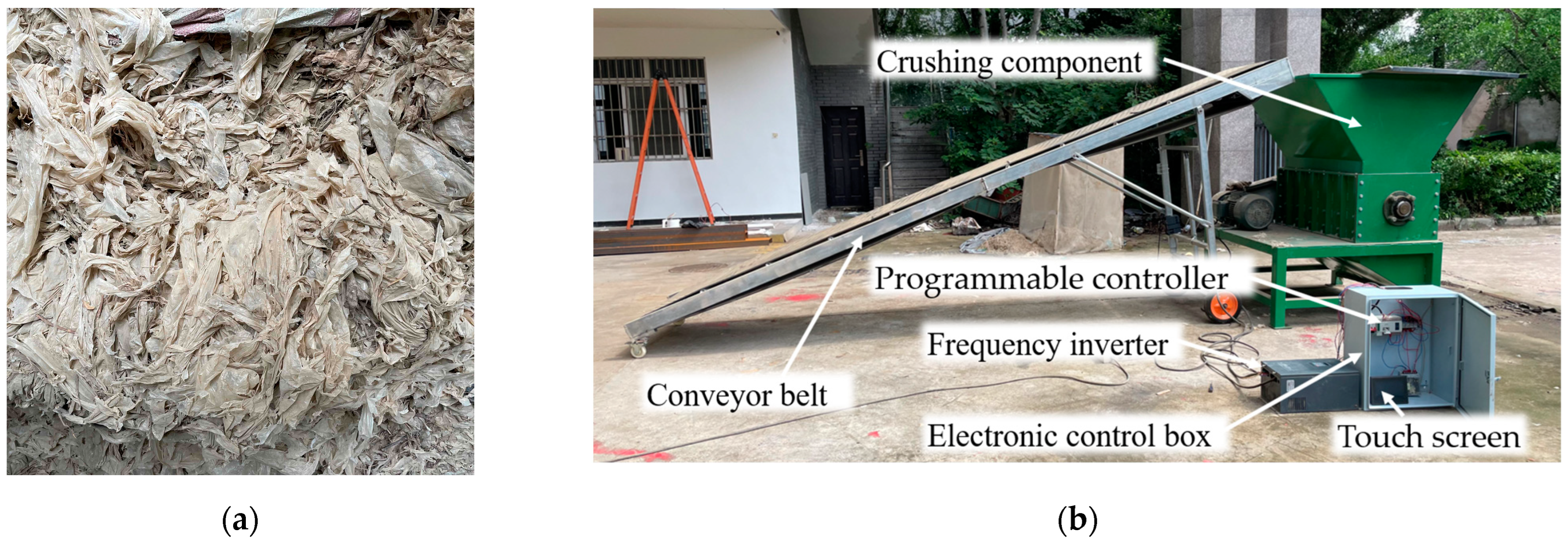
4.1. Materials and Equipment

The crushing test was conducted in mid-July 2023 at the Agricultural Machinery Laboratory of the Institute of Agricultural Mechanization, Ministry of Agriculture and Rural Affairs, in Nanjing, China. The waste plastic film was collected from cotton fields around Korla City in Xinjiang, as shown in Figure 8a. Before the crushing test, the contents of various components in the waste plastic film were determined, excluding impurities, such as stones, plastics, and cotton balls. The components were placed into three categories: film, cotton stalks, and soil impurities. Ten samples of approximately 2 kg ± 0.5 kg were collected, and the average content of each component was determined. The results for the contents showed that film, cotton stalks, and soil impurities accounted for 15.32%, 17.84%, and 66.84%, respectively. The film was low-density polyethylene with a thickness of 0.01 mm, and it had an aging time of approximately 180 days. The cotton stalks were the stem and root residues of harvested cotton in Xinjiang.
The toothed-plate single-roller crushing device, as shown in Figure 8b, mainly consists of the following components: a conveyor belt (manufactured by Wolong Hardware Technology Co., Ltd., Liuan City, China); a Jiale JAC580 frequency inverter (manufactured by Zhejiang Jiale Technology Co., Ltd., Haiyan County, China); an electrical control box (manufactured by Gechele Electrical Co., Ltd., Wenzhou City, China); a Xinje XC3-24RT-E programmable controller and TG765 touchscreen (manufactured by Xinje Electric Co., Ltd., Wuxi City, China); and a crushing component (developed by the Institute of Agricultural Mechanization, Ministry of Agriculture and Rural Affairs, Nanjing, China).

4.2. Assessment Indicators and Test Scheme

In line with the recycling demands of plastic film processing companies, a three-factor, three-level orthogonal test was conducted with the size qualification rate of crushed film and the impurity content as optimization indexes. Referring to previous research on cleaning and separation equipment [22,23,25], film and impurities are separated better when the length of the crushed film is in the range of [50, 500] mm. Thus, a length in the range of [50, 500] mm was taken as the qualified size of the crushed film, which is defined as follows:
Y 1 = M Q M A × 100 %
where Y 1 is the size qualification rate of the crushed film, %; M Q is the mass of the crushed film with qualified length, g; and M A is the net film mass of crushed materials, g.
The impurities in the crushed materials included cotton stalks, soil impurities, and film debris. The impurity content of the crushed film was calculated as follows:
Y 2 = M C M T × 100 %
where Y 2 is the impurity content of the crushed film, %; M C is the mass of impurities in the crushed film, g; and M T is the total mass of crushed materials, g.
Before the test, it is important to prepare adequate test materials. The sampling process should pay attention to minimize the loss of impurities in the materials. The mass of each sample was 2.0 ± 0.2 kg, and the material was evenly spread on the conveyor belt, as shown in Figure 9. After that, the crushing device was started, and the conveyor belt was started after the crushing roller ran steadily. When the discharge hopper had no material coming out, the main switch was turned off and samples of the crushed mixture were taken. Each sample group had a mass of 300 g ± 10 g. Finally, the crushed mixture was separated into film and impurities, and the size qualification rate and impurity content of the crushed film were calculated. Each test group was repeated 3 times, and the data for each group was the average of 3 repeated tests.
Based on the motion and mechanical analysis of the crushing process, it is known that the feeding speed, V 0 ; the number of toothed plates, Z ; and the crushing roller rotation speed, ω , have a great impact on the indicators. In accordance with preliminary experiments, the feeding speed, V 0 , was determined to be [0.25, 0.40] m/s; the numbers of toothed plates, Z , were 6, 12, and 18; and the crushing roller rotation speed, ω , was [600, 900] r/min. The factors and levels for the Box–Behnken orthogonal test are shown in Table 2.

5. Analysis and Verification of Crushing Test Results

5.1. Crushing Test Results

The test design followed a three-factor, three-level Box–Behnken approach, consisting of a total of 17 tests. The test schemes and outcomes were generated using Design-Expert 12.0 software, as illustrated in Table 3.

5.2. Significance Test and Regression Model Construction

ANOVA and regression analyses were conducted on the data from Table 3, and multivariate regression models were established.
(1) Significance analysis of the size qualification rate of crushed film
The regression and variance analysis of the size qualification rate of crushed film is shown in Table 4. All variables have a significant impact on the model. Specifically, the p-values for X1, X2, X3, X1X2, X1X3, X2X3, X12, and X32 are less than 0.01, indicating extremely significant effects on the model. The p-value for X12 falls in the range of 0.01 to 0.05, indicating a significant effect on the model. The ranking of variables based on their significance in influencing the model, from highest to lowest, is as follows: X22 > X2 > X3 > X1X3 > X1X2 > X2X3 > X1 > X32 > X12.
The quadratic regression model for the size qualification rate of crushed film is shown in Equation (10). The model has a p-value of <0.0001, indicating its extreme significance. The lack of fit has a p-value > 0.1, indicating a good fit for this quadratic regression model. The adjusted R2 for the model is 0.9611, and the predicted R2 is 0.8829, with a difference of less than 0.2 between them. The coefficient of variation (CV) is 1.16%, indicating good reliability and stability of the model data. The signal-to-noise ratio is 18.8351, significantly greater than 4, indicating that the quadratic regression model is reliable and capable of accurately predicting the size qualification rate of crushed film.
Y 1 = 87.46 + 1.23 X 1 2.29 X 2 + 1.65 X 3 1.78 X 1 X 2 2.31 X 1 X 3 + 1.76 X 2 X 3 1.12 X 1 2 7.27 X 2 2 1.47 X 3 2
(2) Significance analysis of the impurity content of crushed film
The regression and variance analysis of the impurity content of crushed film is shown in Table 5. The p-values for X1, X2, X3, X1X3, X2X3, X22, and X32 are less than 0.01, indicating extremely significant effects on the model. The p-value for X1X2 falls in the range of 0.01 to 0.05, indicating a significant effect on the model. The p-value for X12 is greater than 0.05, indicating that its influence on the model is not significant. The ranking of variables based on their significance in influencing the model, from highest to lowest, is as follows: X22 > X32 > X3 > X2 > X1 > X1X3 > X2X3 > X1X2 > X12.
Regarding the quadratic regression model for the impurity content of crushed film, the model has a p-value of <0.0001, indicating its extreme significance. The lack of fit has a p-value > 0.1, indicating a good fit for this quadratic regression model. The adjusted R2 for the model is 0.9869, and the predicted R2 is 0.9538, with a difference of less than 0.2 between them. The coefficient of variation (CV) is 3.56%, indicating good reliability and stability of the model data. The signal-to-noise ratio is 29.3490, significantly greater than 4, indicating that the quadratic regression model is reliable and capable of accurately predicting the impurity content of crushed film. Finally, the non-significant variables, X12, can be elminated. The model is shown in Equation (11).
Y 2 = 9.07 + 0.91 X 1 + 1.00 X 2 1.46 X 3 + 0.78 X 1 X 2 1.16 X 1 X 3 + 0.95 X 2 X 3 + 6.90 X 2 2 + 2.23 X 3 2

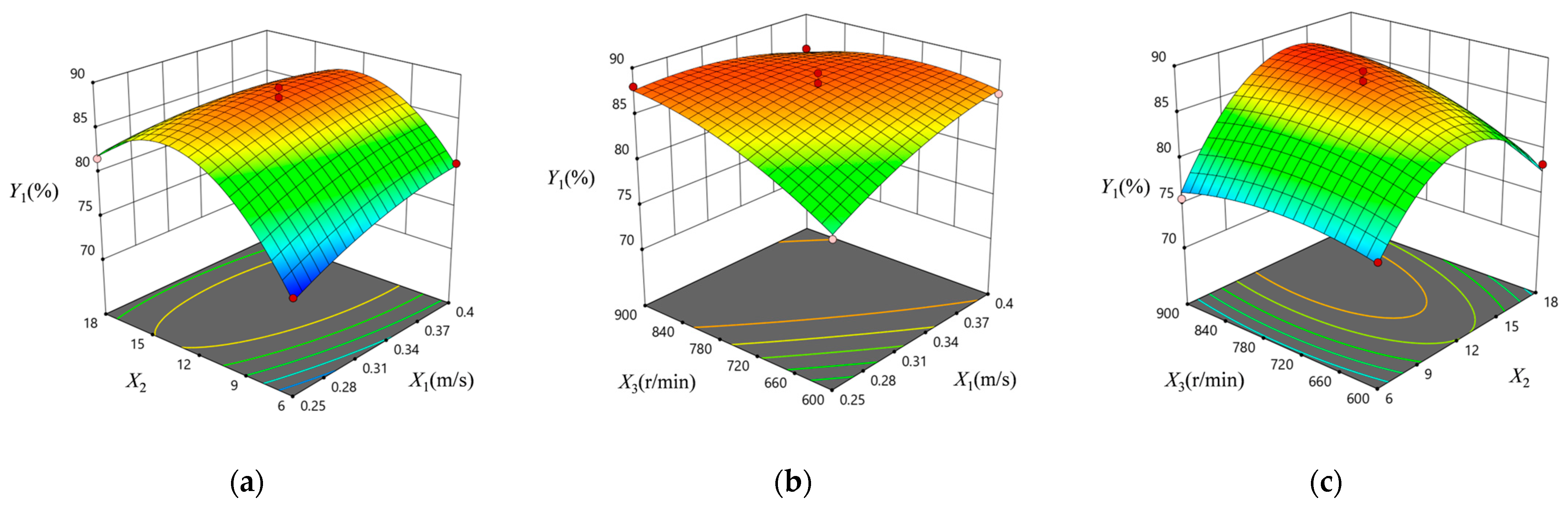
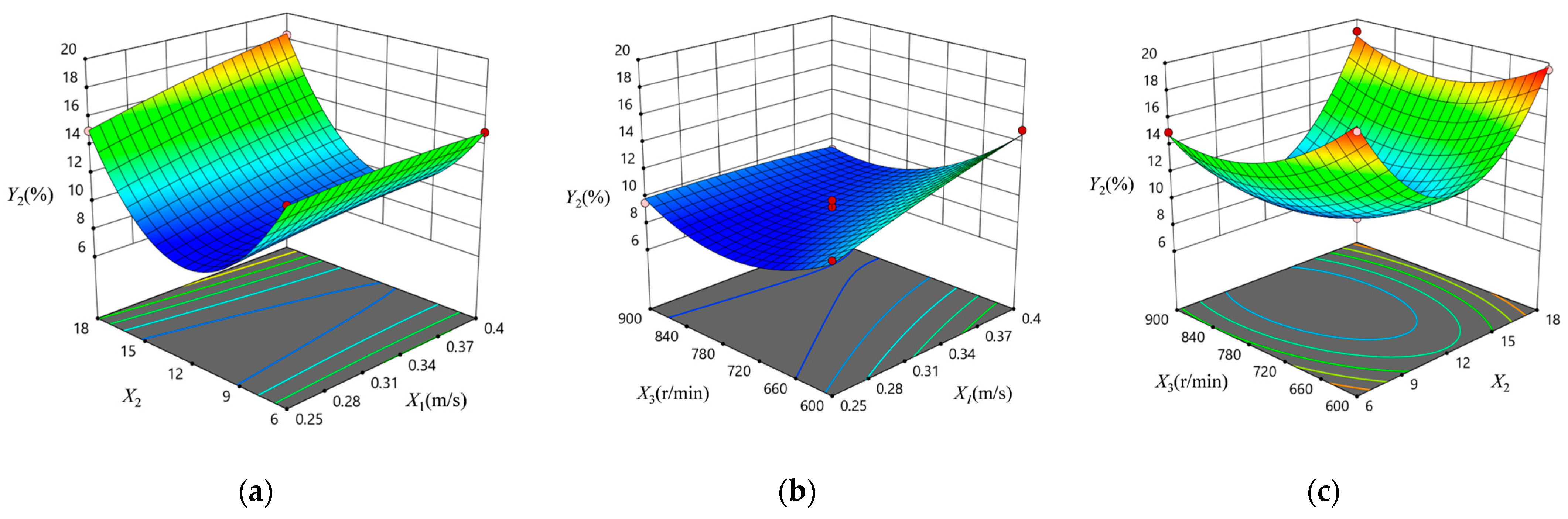
5.3. Influence of Interaction Factors on Indicators

(1) The influence of interaction factors on the size qualification rate of crushed film
As shown in Figure 10, the response surface and contour were generated using Design-Expert 12.0 software to analyze the effects of the feeding speed, the number of toothed plates, and the crushing roller rotation speed on the size qualification rate of crushed film. Figure 10a–c represent the response surface for the effects of X1X2, X1X3, and X2X3 on Y1, respectively. The contours of the three figures are all elliptical, indicating a strong interaction between any two factors.
From Figure 10a, it can be observed that when X1 is 0.25 m/s, Y1 initially increases from 74.11% to 85.52% and then decreases to 81.64% with increasing levels of X2. Similarly, when X1 is 0.4 m/s, Y1 initially exhibits an increase from 80.05% to 87.58% and then decreases to 80.47% as the X2 level increases. The curvature of the surface in the direction of X2 is more pronounced than that of X1, indicating that X2 has a more significant impact on Y1, consistent with the previous variance analysis results. This is because, at a constant feeding speed, a higher number of toothed plates can lead to excessive crushing of waste plastic film. Conversely, a lower number of toothed plates can result in incomplete crushing of waste plastic film. Both can lead to a lower size qualification rate of crushed film. Figure 10b shows that when X3 is 600 r/min, Y1 continuously increases from 79.18% to 89.01% as the X1 level increases, and conversely, when X3 is 900 r/min, Y1 continuously decreases to 85.92% as the X1 level increases. Figure 10c reveals that when X3 is at 600 r/min, Y1 initially increases from 76.70% to 84.18% and then decreases to 78.35% as the X2 level increases, and when X3 is at 900 r/min, Y1 initially exhibits an increase from 75.57% to 88.83% and then decreases to 84.26% as the X2 level increases. Additionally, from the number of contour lines, it can be seen that at lower rotation speeds, the number of teeth has a greater impact on Y1. The curvature of the surface in the direction of X2 is more pronounced than that of X3, indicating that X2 has a more significant effect on Y1, consistent with the variance analysis results. This is because at a higher crushing roller rotation speed, the region of crushing is approximately cylindrical, and the influence of the number of toothed plates on the crushing effect is “masked” by the high roller rotation speed.
(2) The influence of interaction factors on the impurity content of crushed film
To investigate the impact of interaction factors on the impurity content of the crushed film, the response surface and contour of the impurity content were created, as shown in Figure 11. Figure 11a–c represent the response surfaces for the interaction effects of X1X2, X1X3, and X2X3 on Y2, respectively. The contours for X1X2 and X2X3 are both elliptical, indicating a strong interaction between X1 and X2, as well as X2 and X3.
From Figure 11a, it can be observed that when X2 is 6, there is little change in the value of Y2 with an increase in the X1 level. However, when X2 is 18, an increase in the X1 level results in a continuous increase from 15.04% to 18.33% in Y2. The curvature of the surface in the X2 direction is more pronounced than that in the X1 direction, indicating that X2 has a more significant impact on Y2 than X1, which is consistent with the variance analysis results. This suggests that when the number of toothed plates is constant, an increase in the feeding speed leads to a higher crushing mass per second, affecting the tapping effect of the toothed plates on the materials, ultimately leading to an increase in the impurity content of the crushed film. From Figure 11b, it can be seen that when X3 is 600 r/min, Y2 continuously increases numerically from 10.72% to 14.95% with an increase in the X1 level. However, when X3 is 900 r/min, Y2 slowly decreases from 9.56% to 9.15%. According to the previous variance analysis, X3 has a more significant impact on Y2 than X1. Therefore, it is speculated that there is an effect of feeding speed on the impurity content when the crushing roller rotation speed is relatively low. However, when the crushing roller rotation speed reaches a higher value, the effect of the feeding speed on the impurity content is overshadowed. From Figure 11c, it can be observed that when X3 is 600 r/min, an increase in the X2 level initially results in a decrease from 19.23% to 13.16% in Y2, followed by an increase to 19.51. Similarly, when X3 is 900 r/min, an increase in the X2 level initially leads to a decrease from 14.98% to 9.76% in Y2, followed by an increase to 19.05%. This indicates that the number of toothed plates can affect the impurity content of the crushed film.

5.4. Test Verification and Result Analysis

Using Design-Expert software and considering the actual working conditions and performance requirements of the crushing device, an optimization analysis was conducted on the regression models mentioned. The optimization and verification solutions are presented in Table 6.
As shown in Table 6, under the conditions of a feeding speed of 0.304 m/s, the number of toothed plates being 12.368, and a crushing roller rotation speed of 815.435 r/min, the crushed film had a size qualification rate of 87.94% and an impurity content of 8.83%. To validate the accuracy of the optimized theoretical model, verification tests were conducted based on the test conditions; the feeding speed was set at 0.30 m/s, the number of toothed plates was 12, and the crushing roller rotation speed was selected as 815 r/min. Three validation tests were conducted following the test scheme in 3.2, and the results were averaged. The results showed that the crushed film had a size qualification rate of 82.55%, which had an error of 6.14% compared to the predicted value. The impurity content of the crushed film was 9.57%, with an error of 8.38% compared to the predicted value. Both error values were within 9%, indicating that the optimized model is reliable and can predict the size qualification rate and the impurity content of crushed film under different device parameters.

6. Conclusions

A toothed-plate single-roller crushing device for waste plastic film was designed, and its working process and a crushing component design analysis have been described. Through theoretical analysis, it was found that the key factors affecting the crushing effect of the equipment include the feeding speed, the number of toothed plates, and the crushing roller rotation speed. Using the Box–Behnken design experimental method and considering the feeding speed, the number of toothed plates, and the crushing roller rotation speed as factors, a three-factor, three-level quadratic polynomial model was established with the size qualification rate and the impurity content of crushed film as the optimization indexes. The analysis results indicate that the size qualification rate and impurity content of the crushed film are 87.94% and 8.83%. After considering practical conditions, the actual verification parameters were determined; the feeding speed was set at 0.30 m/s, the number of toothed plates was 12, and the crushing roller rotation speed was selected as 815 r/min. Finally, verification tests were conducted, resulting in an actual size qualification rate of 82.551% and an impurity content of 9.57%. The errors compared to the predicted values were 6.13% and 8.38%, respectively. Both error values were within 9%, indicating that the optimized model is reliable and predictive. The design of the toothed-plate single-roller crushing device reduces cleaning difficulty and recycling processing costs and improves the quality of recycled products. Additionally, it will greatly increase the efficiency of the resource utilization of waste plastic film. However, there are still weaknesses in the crushing device in this study; for example, the toothed plates are not capable of crushing larger stones. Therefore, in future research, the material and shape of the toothed plates should be optimized to achieve the purpose of crushing stones without damage to the toothed plates.

Author Contributions

Conceptualization, K.G.; methodology, K.G. and H.Y.; software, K.G.; validation H.S. and H.Y.; formal analysis, X.C.; investigation, M.C.; resources, F.G.; data curation, K.G.; writing—original draft preparation, K.G.; writing—review and editing, Z.H.; visualization, Z.H.; supervision, M.C.; project administration, Z.H.; funding acquisition, F.W. All authors have read and agreed to the published version of the manuscript.

Funding

Central Public-interest Scientific Institution Basal Research Fund, grant numbers S202305 and S202304.

Institutional Review Board Statement

Not applicable.

Informed Consent Statement

Not applicable.

Data Availability Statement

The data presented in this study are available in the article.

Conflicts of Interest

The authors declare no conflict of interest. The authors declare that this study received funding from Central Public-interest Scientific Institution Basal Research Fund. The funder had the following involvement with the study: Hongguang Yang and Mingzhu Cao.

References

  1. Anzalone, A.; Cirujeda, A.; Aibar, J.; Pardo, G.; Zaragoza, C. Effect of Biodegradable Mulch Materials on Weed Control in Processing Tomatoes. Weed Technol. 2010, 24, 369–377. [Google Scholar] [CrossRef]
  2. Li, B.; Liu, Q.; Yao, Z.; Ma, Z.; Li, C. Mulch Film: An Overlooked Diffuse Source of Organic Ultraviolet Absorbers in Agricultural Soil. Environ. Pollut. 2023, 318, 120935. [Google Scholar] [CrossRef]
  3. Chen, Y.; Wu, C.; Zhang, H.; Lin, Q.; Hong, Y.; Luo, Y. Empirical estimation of pollution load and contamination levels of phthalate esters in agricultural soils from plastic film mulching in China. Environ. Earth Sci. 2013, 70, 239–247. [Google Scholar] [CrossRef]
  4. Bandopadhyay, S.; Martin-Closas, L.; Pelacho, A.M.; DeBruyn, J.M. Biodegradable Plastic Mulch Films: Impacts on Soil Microbial Communities and Ecosystem Functions. Front. Microbiol. 2018, 9, 819. [Google Scholar] [CrossRef] [PubMed]
  5. Ingman, M.; Santelmann, M.V.; Tilt, B. Agricultural water conservation in China: Plastic mulch and traditional irrigation. Ecosyst. Health Sustain. 2015, 1, 1–11. [Google Scholar] [CrossRef]
  6. Ma, L.; Chen, D.; Zhou, G. Technologies and Machinery of Waste Agricultural Plastic Film Granulitization in China. China Resour. Compr. Util. 2005, 2015, 13–17. [Google Scholar]
  7. Zhao, Y.; Chen, X.; Wen, H.; Zheng, X.; Niu, Q.; Kang, J. Research Status and Prospect of Control Technology for Residual Plastic Film Pollution in Farmland. Trans. Chin. Soc. Agric. Mach. 2017, 48, 1–14. [Google Scholar]
  8. China Statistical Yearbook on Environment; China Statistics Press, National Bureau of Statistics Ministry of Ecology and Environment: Beijng, China, 2023.
  9. Wang, Y.; Ma, Q. The Influencing Factors and Empirical Study on the Recovery by Behavior of the Cotton Planters Residual Film in Xinjiang—Based on the Research Data of the Cotton Planters. Chin. J. Agric. Resour. Reg. Plan. 2019, 40, 53–59. [Google Scholar]
  10. Yu, W.; Ling, Y.; Xia, X.; Adili, T. Current Situation of Recycling Used Mulch on Farmland in Xinjiang and Suggestions for Countermeasures. Xinjiang Agric. Sci. Technol. 2023, 2023, 43–44. [Google Scholar]
  11. Wang, J.; Fu, W.; Wang, W.; Li, B. Design of Sms-1500 Type Straw Chopping and Plastic Film Residue Collecting Machine. Trans. Chin. Soc. Agric. Eng. 2011, 27, 168–172. [Google Scholar]
  12. You, J.; Chen, X.; Zhang, B.; Wu, J. Design and Experiment of 4jsm-2000 Type Combined Operation Machine for Cotton Stalk Chopping and Residual Plastic Film Collecting. Trans. Chin. Soc. Agric. Eng. 2017, 33, 10–16. [Google Scholar]
  13. Liang, R.; Zhang, B.; Zhou, P.; Li, Y.; Meng, H.; Kan, Z. Cotton Length Distribution Characteristics in the Shredded Mixture of Mechanically Recovered Residual Films and Impurities. Ind. Crops Prod. 2022, 182, 114917. [Google Scholar] [CrossRef]
  14. Tuck, C.; O’Dogherty, M.; Baker, D.; Gale, G. Field experiments to study the performance of toothed disc mowing mechanisms. J. Agric. Eng. Res. 1991, 50, 93–106. [Google Scholar] [CrossRef]
  15. Zhong, H.; Liu, X.; Yuan, M.; Cai, H. The Structure and Design of Plastic Film Smashing Machine. J. Cent. South Univ. For. Technol. 2009, 29, 184–188. [Google Scholar]
  16. Liao, P.; Liu, K.; Chen, M.; Wang, Z.; Zhang, A. Design and Experiment of a Roller Type Cotton Stalk Cutting Mechanism. J. China Agric. Univ. 2018, 23, 131–138. [Google Scholar]
  17. Li, L.; Yang, L.; Zhang, D.; Wan, C.; Xie, T.; Tian, Q. Finite Element Analysis on Key Parts of New Type Rubber Crusher. China Rubber Ind. 2019, 66, 377–381. [Google Scholar]
  18. Guo, K.; Cao, M.; Gu, F.; Wu, F.; Yang, H.; Xu, H.; Hu, Z. Mechanical Properties of Metallocene Linear Low-Density Polyethylene Mulch Films Correlate with Ultraviolet Irradiation and Film Thickness. Sustainability 2023, 15, 6713. [Google Scholar] [CrossRef]
  19. Liu, X.; Yang, X.; Li, Q. Research on Waste Plastic Membrane Separation in the Cyclone Based on Fluent. Ind. Saf. Environ. Prot. 2016, 42, 38–41. [Google Scholar]
  20. Sonde, V.M.; Belkhode, P.N.; Sakhale, C.N. Physical and Mechanical Characteristics for Cotton and Pigeon Pie as Agriculture Residues. Int. J. Appl. Innov. Eng. Manag. (IJAIEM) 2015, 4, 156–169. [Google Scholar]
  21. Guo, K.; Cao, M.; Yang, H.; Luo, W.; Qin, M.; Wu, F.; Gu, F.; Hu, Z. A Preliminary Determination of Mechanical and Suspension Properties of Waste Mulch Film and Cotton Stalk. Agriculture 2023, 13, 1572. [Google Scholar] [CrossRef]
  22. He, H.; Hu, B.; Pan, F.; Luo, X.; Guo, M.; Xie, Y.; Chen, X. Effects and Experiment on Settlement and Aggregation Behavior of Plastic Film and Cotton Stalk under the Action of Disturbing Water by the Impeller. Trans. Chin. Soc. Agric. Eng. 2021, 37, 86–95. [Google Scholar]
  23. Peng, Q.; Li, C.; Kang, J.; Shi, G.; Zhang, H. Improved Design and Test on Pneumatic Cylinder Sieve Film Hybrid Separator. Trans. Chin. Soc. Agric. Mach. 2020, 51, 126–135. [Google Scholar]
  24. Chen, J.; Zhang, L.; Tan, T. Study on Shearing Properties of Soybean Straw. J. Hunan Agric. Univ. (Nat. Sci.) 2017, 43, 98–102. [Google Scholar]
  25. Kang, J.; Xie, C.; Wang, X.; Chen, Y.; Wang, C.; Peng, Q. Design and Test of Screen Hole Clearing Device for Trommel Sieve Type Membrane Miscellaneous Wind Separator. Trans. Chin. Soc. Agric. Mach. 2022, 53, 91–98. [Google Scholar]
  26. Zang, J.; Lin, M. Analysis and Design of Shearing-Typed Single-Roll Shredder for Household Garbage. Min. Process. Equip. 2017, 45, 35–38. [Google Scholar]
  27. Zhong, S.; Wang, Q.; Fang, H.; Wang, M. Modal Analysis of Roller in Used Mulch Shredder. Mech. Eng. 2018, 2018, 43–45. [Google Scholar]
  28. China Agricultural Mechanization Scientific Research Institute. Agricultural Machinery Design Handbook; China Agricultural Science and Technology Press: Beijing, China, 2007. [Google Scholar]
  29. Tosun, A.; Konak, G. Development of a model estimating energy consumption values of primary and secondary crushers. Arab. J. Geosci. 2014, 8, 1133–1144. [Google Scholar] [CrossRef]
Figure 1. The toothed-plate single-roller crushing device for waste plastic film. Components: 1. electrical control box; 2. programmable controller; 3. touchscreen; 4. frequency inverter; 5. feeding hopper; 6. transmission components; 7. discharge hopper; 8. crushing roller; 9. crushing box; 10. motor; 11. frame; 12. conveyor belt. The dashed yellow lines represent the electronic wires between each component and the controller.
Applsci 13 11650 g001
Figure 2. The structure of the toothed plate. (a) Moving toothed plate and (b) fixed toothed plate.
Applsci 13 11650 g002
Figure 3. The crushing roller structure.
Applsci 13 11650 g003
Figure 4. The three types of crushing rollers: (a) T1, (b) T2, and (c) T3. The grids represent the arrangement of the toothed plates, the black points represent the toothed plates, and the horizontal lines represent the position of the toothed-plate holders, 1, 2 and 3 represent the serial number of the toothed-plate holders.
Applsci 13 11650 g004
Figure 5. The modal analysis of the first six orders for T1, T2, and T3 crushing rollers.
Applsci 13 11650 g005
Figure 6. Motion analysis of waste plastic film feeding process.
Applsci 13 11650 g006
Figure 7. Mechanical analysis of waste plastic film crushing.
Applsci 13 11650 g007
Figure 8. Test materials and equipment. (a) The waste plastic film and (b) the toothed-plate single-roller crushing device.
Applsci 13 11650 g008
Figure 9. Crushing procedure.
Applsci 13 11650 g009
Figure 10. Response surfaces and contours for the effect of interaction factors on Y1. (a), (b) and (c) show the interaction effect of X2X1, X3X1 and X3X2 on Y1, respectively.
Applsci 13 11650 g010
Figure 11. Response surfaces and contours for the effect of interaction factors on Y2. (a), (b) and (c) show the interaction effect of X2X1, X3X1 and X3X2 on Y2., respectively.
Applsci 13 11650 g011
Table 1. First six orders of frequency and maximum deformation of T1, T2, and T3 crushing rollers.
ItemsCrushing RollersMode 1Mode 2Mode 3Mode 4Mode 5Mode 6
Excitation
frequency (Hz)
T1401.71402.27467.841231.231234.821265.42
T2400.73400.87459.131226.911227.601260.52
T3400.75401.64458.601225.781226.691264.03
Maximum
deformation (mm)
T11.851.792.892.261.881.46
T21.791.792.861.982.011.47
T31.851.792.852.392.254.12
Table 2. Test factors and levels.
LevelsFeeding Speed
X1 (m/s)
Number of Cutter Toothed Plates X2Crushing Roller Rotation Speed X3 (r/min)
−10.2506600
00.32512750
10.40018900
Table 3. Test schemes and results.
No.X1 (m/s)X2X3 (r/min)Y1 (%)Y2 (%)
10.2501875081.6415.04
20.3251275086.658.94
30.3251860078.3519.51
40.325660076.7019.23
50.2501260079.1810.72
60.400675080.0514.94
70.3251275086.779.25
80.3251275087.948.87
90.3251890084.2619.05
100.4001260086.3514.95
110.4001290085.929.15
120.3251275089.018.53
130.2501290088.019.56
140.325690075.5714.98
150.250675074.1114.76
160.4001875080.4718.33
170.3251275086.939.76
Table 4. The regression and variance analysis of the size qualification rate of crushed film.
SourceSum of SquaresdfMean SquareF-Valuep-Value
Model370.06941.1244.90<0.0001 **
X112.13112.1313.240.0083 **
X241.82141.8245.660.0003 **
X321.71121.7123.710.0018 **
X1X212.64112.6413.800.0075 **
X1X321.44121.4423.410.0019 **
X2X312.39112.3913.530.0079 **
X125.3215.325.810.0468 *
X22222.461222.46242.94<0.0001 **
X329.1119.119.950.0160 *
Residual6.4170.9157
Lack of fit2.3630.78800.77910.5640
Pure error4.0541.01
Cor total376.4716
* Significant factor (0.01 < p ≤ 0.05), ** extremely significant factor (p ≤ 0.01), p > 0.05 non-significant factor.
Table 5. The regression and variance analysis of the impurity content of crushed film.
SourceSum of SquaresdfMean SquareF-Valuep-Value
Model272.09930.23135.41<0.0001 **
X16.6416.6429.750.0010 **
X28.0418.0436.010.0005 **
X317.02117.0276.25<0.0001 **
X1X22.4212.4210.830.0133 *
X1X35.3815.3824.110.0017 **
X2X33.5913.5916.080.0051 **
X120.168410.16840.75430.4139
X22200.321200.32897.18<0.0001 **
X3220.84120.8493.36<0.0001 **
Residual1.5670.2233
Lack of fit0.705930.23531.100.4468
Pure error0.857040.2143
Cor total273.6616
* Significant factor (0.01 < p ≤ 0.05), ** extremely significant factor (p ≤ 0.01), p > 0.05 non-significant factor.
Table 6. The optimization and verification solutions.
ItemsX1 (m/s)X2X3 (r/min)Y1 (%)Y2 (%)
Optimization solution0.3012.34815.4487.958.83
Verification solution0.3001281582.559.57
Disclaimer/Publisher’s Note: The statements, opinions and data contained in all publications are solely those of the individual author(s) and contributor(s) and not of MDPI and/or the editor(s). MDPI and/or the editor(s) disclaim responsibility for any injury to people or property resulting from any ideas, methods, instructions or products referred to in the content.

