
Modeling and Testing for Slotted Disk Springs Considering Linearly Gradient Thickness and Friction

Abstract
:1. Introduction
2. Development of an Analytical Model for LGTS Disk Springs
3. Parametric Study
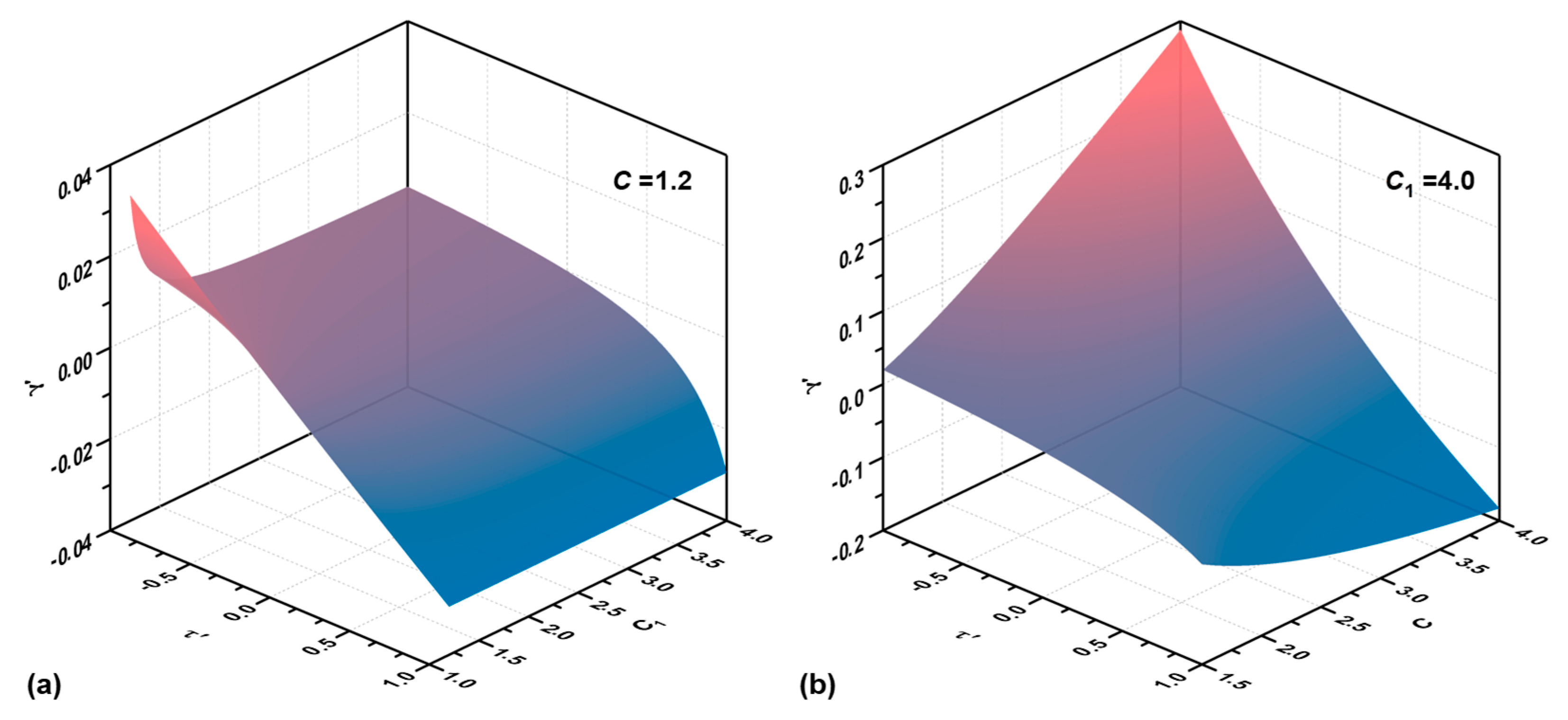
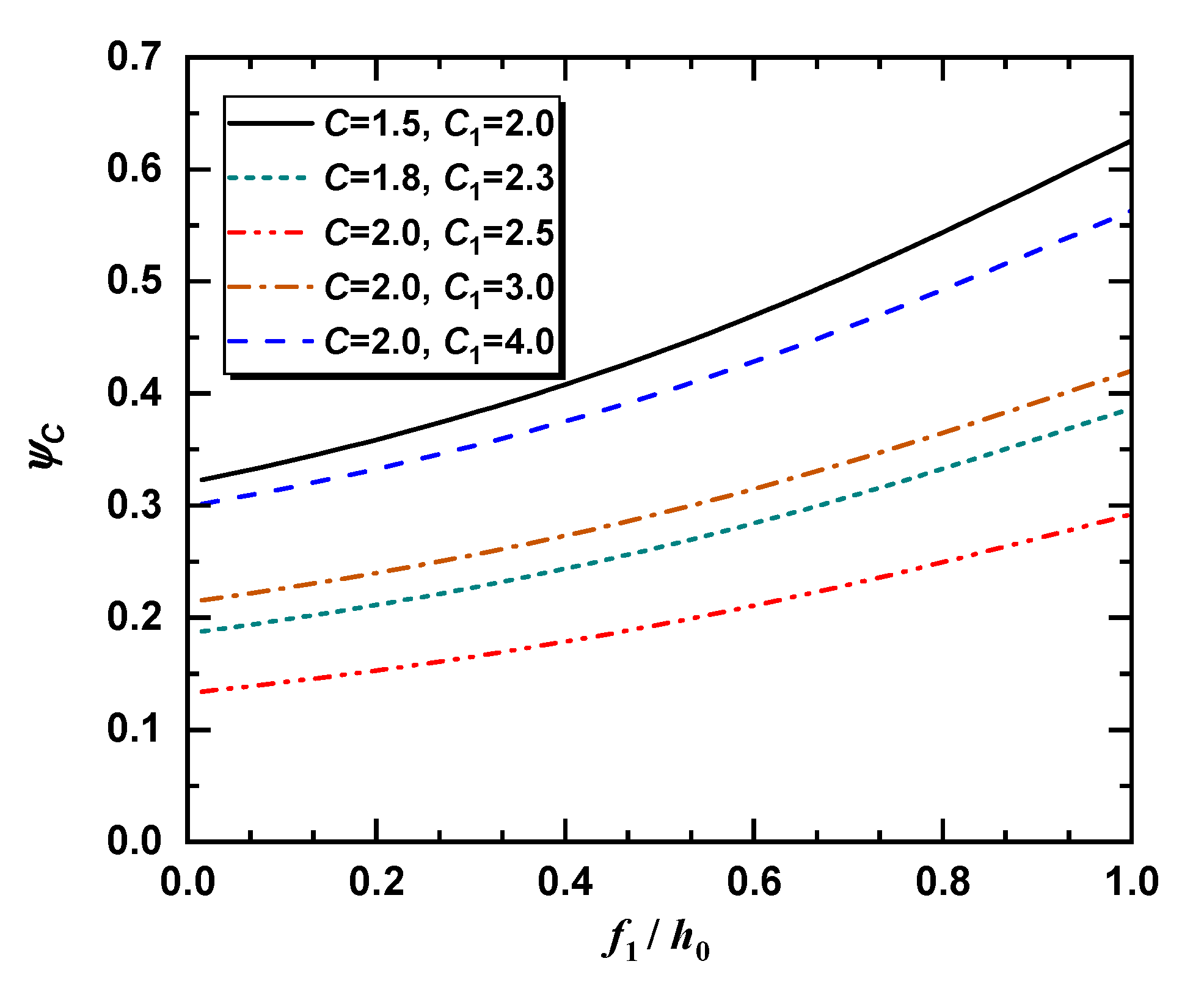
3.1. Relationship between and
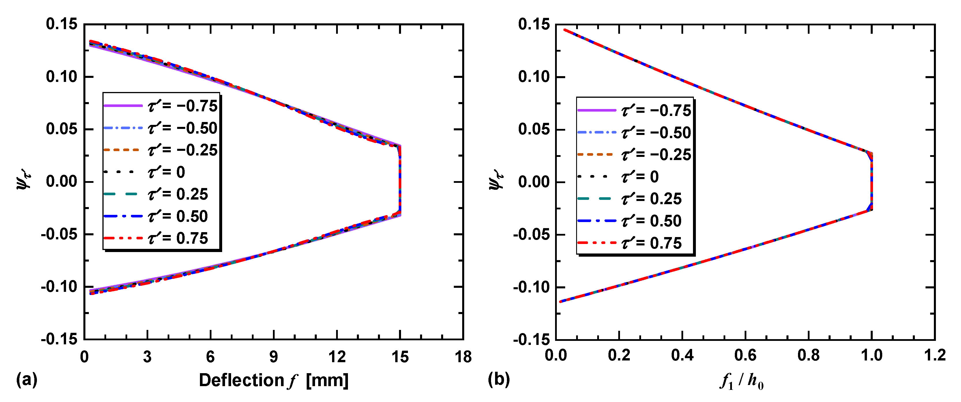
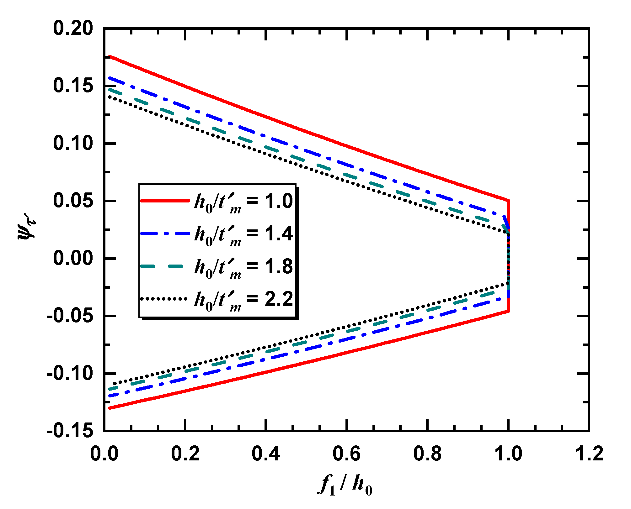
3.2. Effects of on the Neutral Point Radius
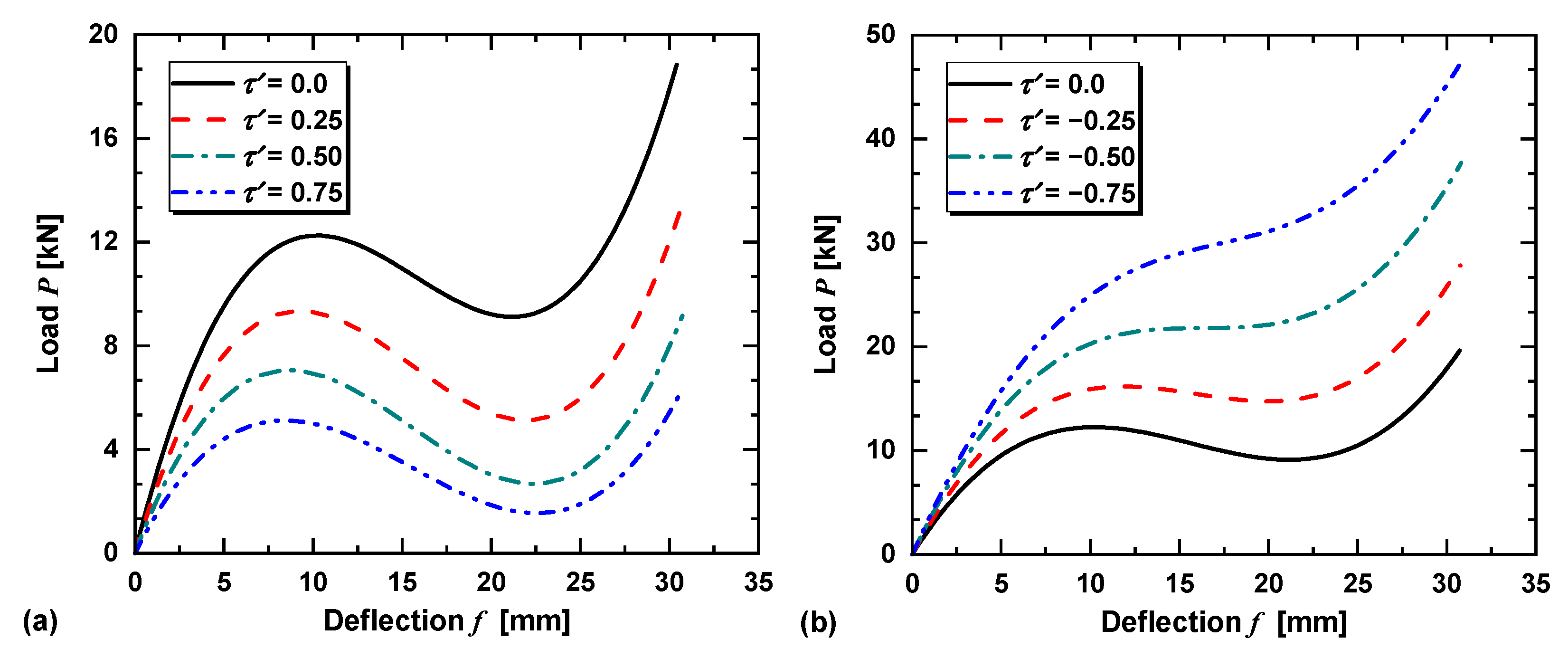
3.3. Effects of on the Load–Deflection Characteristics
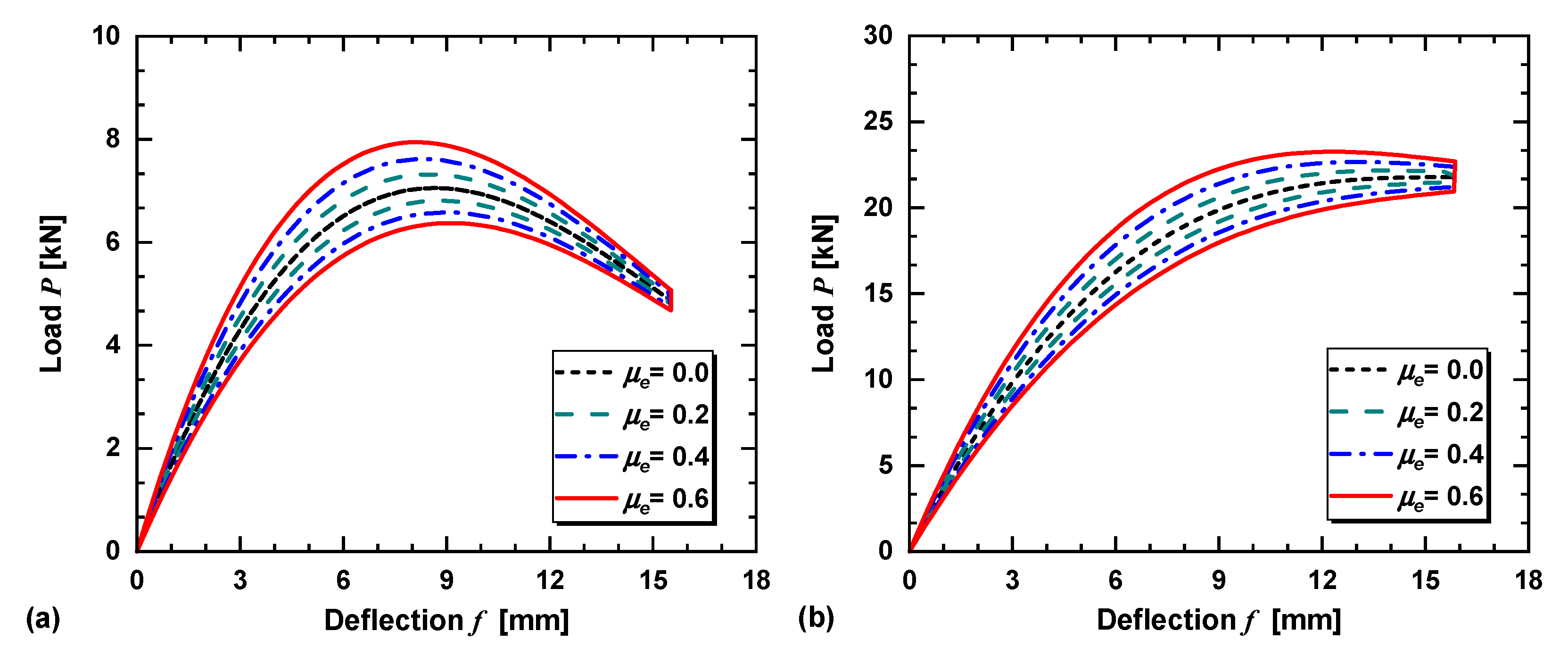
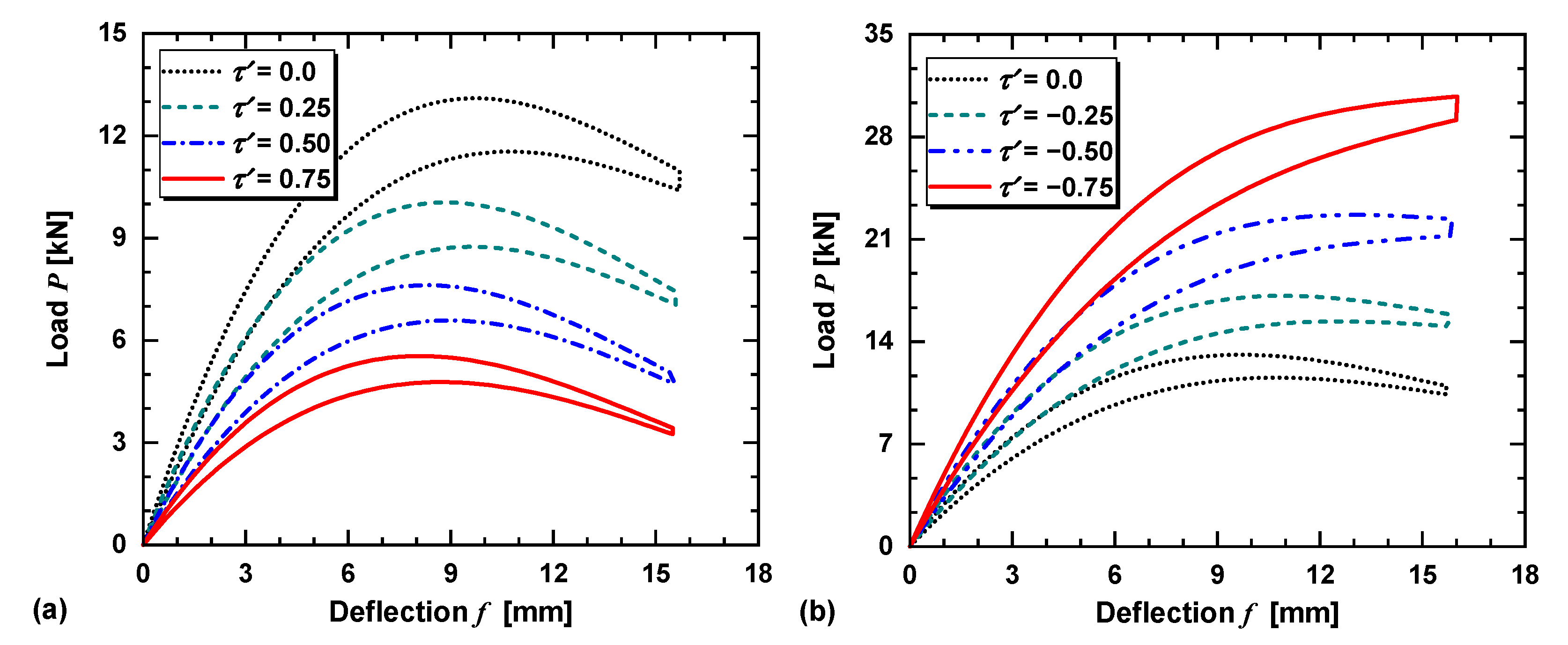
3.4. Effects of on Load–Deflection Characteristics
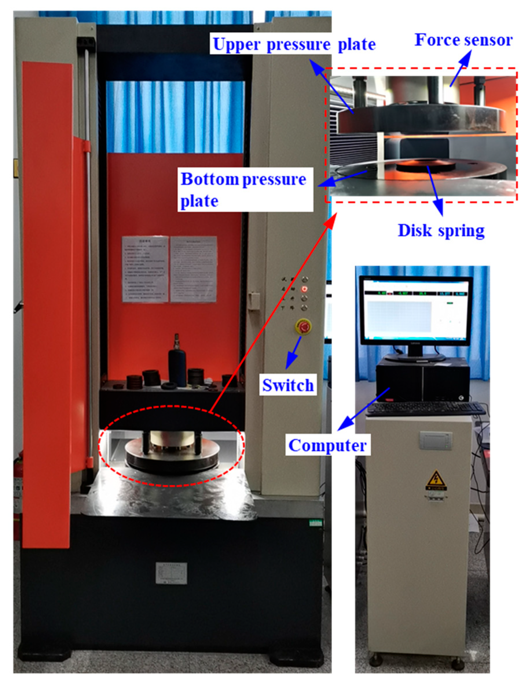
4. Analysis and Experimental Verification
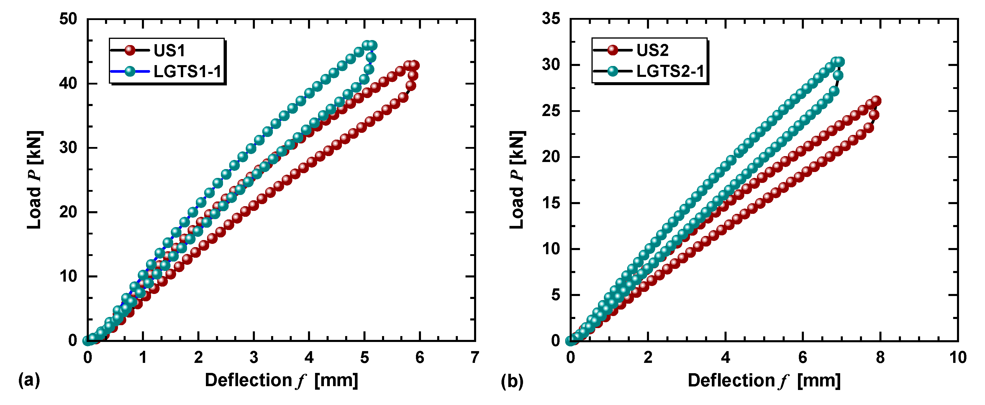
4.1. Experimental Results Analysis
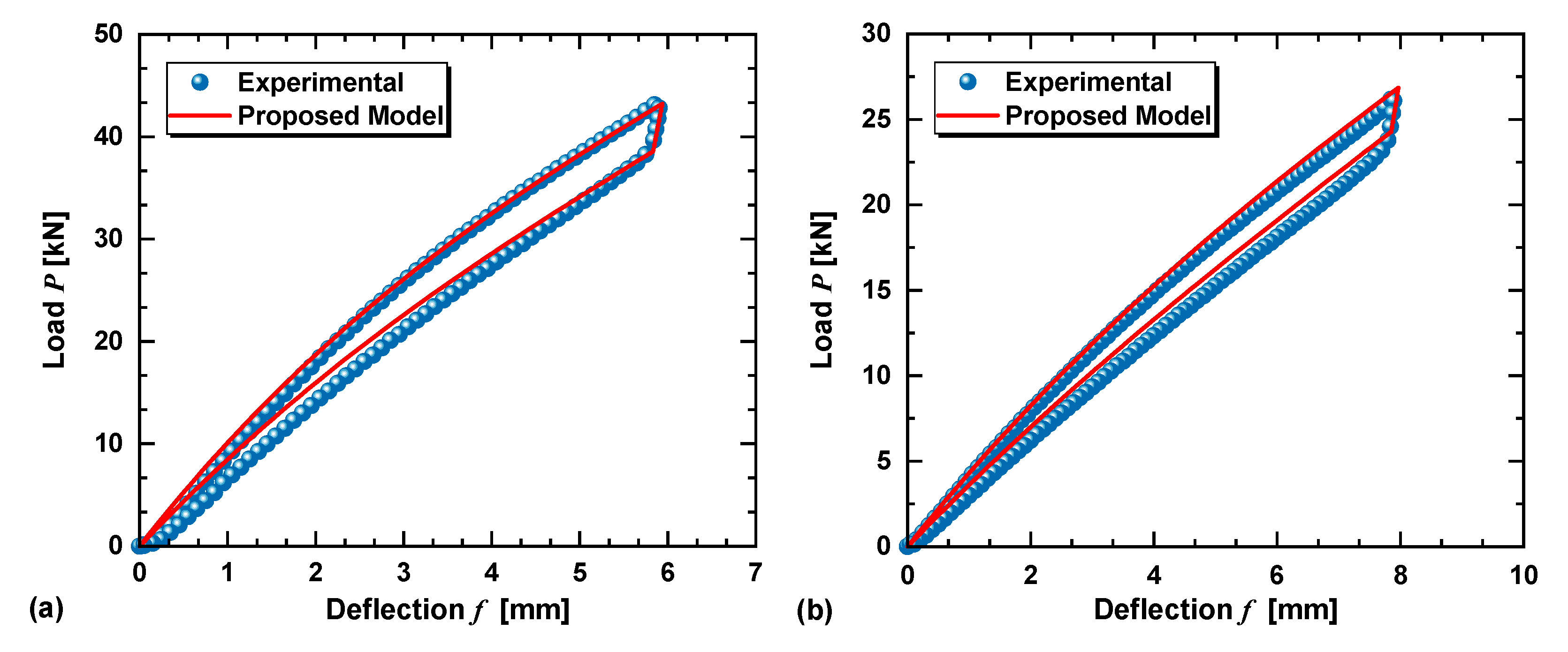
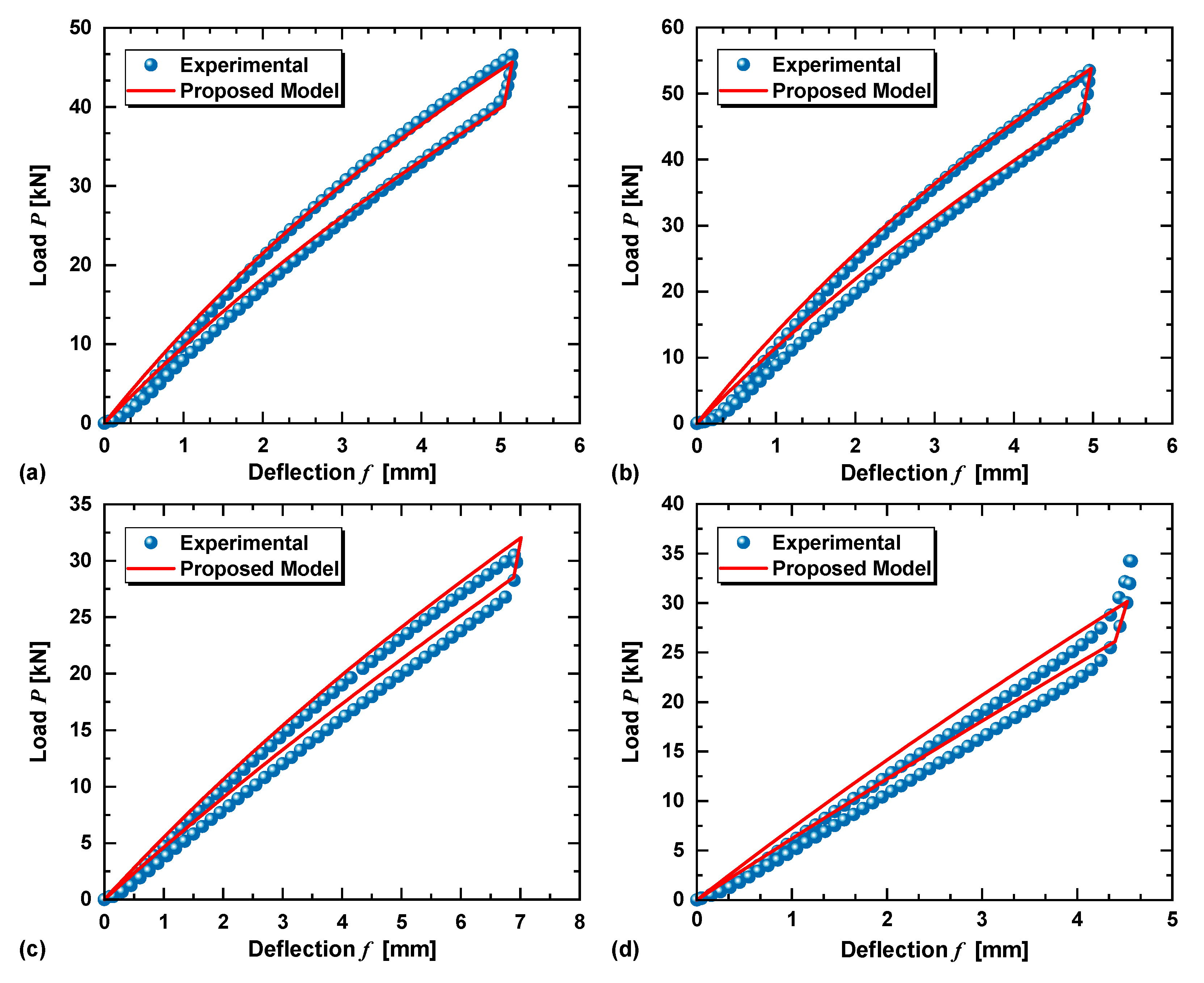
4.2. Verification of the Analytical Model
5. Conclusions
Author Contributions
Funding
Institutional Review Board Statement
Informed Consent Statement
Data Availability Statement
Acknowledgments
Conflicts of Interest
References
- Dharan, C.K.H.; Bauman, J.A. Composite disc springs. Compos. Part A Appl. Sci. Manuf. 2007, 38, 2511–2516. [Google Scholar] [CrossRef]
- Bagavathiperumal, P.; Chandrasekaran, K.; Manivasagam, S. Elastic load-displacement predictions for coned disc springs subjected to axial loading using the finite element method. J. Strain Anal. Eng. Des. 1991, 26, 147–152. [Google Scholar] [CrossRef]
- Patangtalo, W.; Aimmanee, S.; Chutima, S. A unified analysis of isotropic and composite Belleville springs. Thin Walled Struct. 2016, 109, 285–295. [Google Scholar] [CrossRef]
- Shou, M.; Liao, C.; Zhang, H.; Xie, L. A design methodology based on full dynamic model for magnetorheological energy absorber equipped with disc springs. Smart Mater. Struct. 2019, 28, 065020. [Google Scholar] [CrossRef]
- Kaya, N. Optima design of an automotive diaphragm spring with high fatigue resistance. Int. J. Veh. Des. 2006, 40, 126–143. [Google Scholar] [CrossRef]
- Karaduman, A.; Sultan, B.; Yildiz, A. Experimental and numerical fatigue-based design optimisation of clutch diaphragm spring in the automotive industry. Int. J. Veh. Des. 2019, 80, 330–345. [Google Scholar] [CrossRef]
- Shangguan, W.B.; Liu, X.L.; Rakheja, S.; Hou, Q. Effective utilizing axial nonlinear characteristics of diaphragm spring and waveform plate to enhance breakaway performances of a clutch. Mech. Syst. Signal Process. 2019, 125, 123–141. [Google Scholar] [CrossRef]
- Ramhormozian, S.; Clifton, G.C.; MacRae, G.A.; Davet, G.P. Stiffness-based approach for Belleville springs use in friction sliding structural connections. J. Constr. Steel Res. 2017, 138, 340–356. [Google Scholar] [CrossRef]
- Ramhormozian, S.; Clifton, G.C.; MacRae, G.A.; Davet, G.P.; Khoo, H.H. Experimental studies on Belleville springs use in the sliding hinge joint connection. J. Constr. Steel Res. 2019, 159, 81–94. [Google Scholar] [CrossRef]
- D’Antimo, M.; Latour, M.; Cavallaro, G.F.; Jaspart, J.P.; Ramhormozian, S.; Demonceau, J. F Short- and long-term loss of preloading in slotted bolted connections. J. Constr. Steel Res. 2020, 167, 105956. [Google Scholar] [CrossRef]
- Huang, X.C.; Su, Z.W.; Hua, H.X. Application of a dynamic vibration absorber with negative stiffness for control of a marine shafting system. Ocean Eng. 2018, 155, 131–143. [Google Scholar] [CrossRef]
- Shou, M.; Liao, C.; Zhang, H.; Li, Z.; Xie, L. Modeling and testing of magnetorheological energy absorbers considering inertia effect with non-averaged acceleration under impact conditions. Smart Mater. Struct. 2018, 27, 115028. [Google Scholar] [CrossRef]
- Ha, S.H.; Seong, M.-S.; Choi, S.-B. Design and vibration control of military vehicle suspension system using magnetorheological damper and disc spring. Smart Mater. Struct. 2013, 22, 065006. [Google Scholar] [CrossRef]
- Castagnetti, D.; Dallari, F. Design and experimental assessment of an electromagnetic energy harvester based on slotted disc springs. Proc. Inst. Mech. Eng. Part L J. Mater. Des. Appl. 2016, 231, 89–99. [Google Scholar] [CrossRef]
- Castagnetti, D. A Belleville-spring-based electromagnetic energy harvester. Smart Mater. Struct. 2015, 24, 094009. [Google Scholar] [CrossRef]
- Fang, C.; Liang, D.; Zheng, Y.; Yam, M.C.; Sun, R. Rocking bridge piers equipped with shape memory alloy (SMA) washer springs. Eng. Struct. 2020, 214, 110651. [Google Scholar] [CrossRef]
- Schremmer, G. The slotted conical disk spring. J. Eng. Ind. 1973, 95, 765–770. [Google Scholar] [CrossRef]
- Shen, W.; Fang, W. Design of a friction clutch using dual Belleville structures. J. Mech. Des. 2007, 129, 986–990. [Google Scholar] [CrossRef]
- Niu, F.; Meng, L.; Wu, W.; Sun, J.; Zhang, W.; Meng, G.; Rao, Z. Design and analysis of a quasi-zero stiffness isolator using a slotted conical disk spring as negative stiffness structure. J. Vibroeng. 2014, 16, 1769–1785. [Google Scholar]
- Almen, J.O.; Laszlo, A. The uniform-section disk spring. Trans. ASME 1936, 58, 305–314. [Google Scholar] [CrossRef]
- Kobelev, V. Exact shell solutions for conical springs. Mech. Based Des. Struct. Mach. 2016, 44, 317–339. [Google Scholar] [CrossRef]
- Zheng, E.L.; Jia, F.; Zhou, X.L. Energy-based method for nonlinear characteristics analysis of Belleville springs. Thin Walled Struct. 2014, 79, 52–61. [Google Scholar] [CrossRef]
- Patangtalo, W.; Hyer, M.; Aimmanee, S. On the non-axisymmetric behavior of quasi-isotropic woven fiber-reinforced composite Belleville springs. J. Reinf. Plast. Compos. 2015, 35, 334–344. [Google Scholar] [CrossRef]
- Foard JH, D.; Rollason, D.; Thite, A.N.; Bell, C. Polymer composite Belleville springs for an automotive application. Compos. Struct. 2019, 221, 110891. [Google Scholar] [CrossRef]
- Du, X.; Liao, C.; Gan, B.; Zhang, Y.; Xie, L.; Zhang, H. Analytical modeling and experimental verification for linearly gradient thickness disk springs. Thin Walled Struct. 2021, 167, 108153. [Google Scholar] [CrossRef]
- La Rosa, G.; Messina, M.; Risitano, A. Stiffness of variable thickness Belleville springs. J. Mech. Des. 1998, 123, 294–299. [Google Scholar] [CrossRef]
- Saini, P.K.; Kumar, P.; Tandon, P. Design and analysis of radially tapered disc springs with parabolically varying thickness. Proc. Inst. Mech. Eng. Part C J. Mech. Eng. Sci. 2007, 221, 151–158. [Google Scholar] [CrossRef]
- Chaturvedi, R.; Trikha, M.; Simha, K.R.Y. Theoretical and numerical analysis of stepped disk spring. Thin Walled Struct. 2019, 136, 162–174. [Google Scholar] [CrossRef]
- Pedersen, N.L.; Pedersen, P. Stiffness and design for strength of trapezoidal Belleville springs. J. Strain Anal. Eng. Des. 2011, 46, 825–836. [Google Scholar] [CrossRef]
- Karakaya, S. Investigatio of hybrid and different cross-section composite disc springs using finite element method. Trans. Can. Soc. Mech. Eng. 2012, 36, 399–412. [Google Scholar] [CrossRef]
- Ye, Z.M.; Yuan, Y.K. A study of Belleville spring and diaphragm spring in engineering. J. Appl. Mech. Trans. ASME. 1990, 57, 1026–1031. [Google Scholar]
- Fawazi, N.; Lee, J.-Y.; Oh, J.-E. A load-displacement prediction for a bended slotted disc using the energy method. Proc. Inst. Mech. Eng. Part C J. Mech. Eng. Sci. 2011, 226, 2126–2137. [Google Scholar] [CrossRef]
- Fawazi, N.; Yang, I.H.; Kim, J.S.; Lee, J.Y.; Kim, H.S.; Oh, J.E. An inverse algorithm of nonlinear load-displacement for a slotted disc spring geometric design. Int. J. Precis. Eng. Manuf. 2013, 14, 137–145. [Google Scholar] [CrossRef]
- Curti, G.; Montanini, R. On the Influence of Friction in the Calculation of Conical Disk Springs. J. Mech. Des. 1999, 121, 622–627. [Google Scholar] [CrossRef]
- Mastricola, N.P.; Dreyer, J.T.; Singh, R. Analytical and experimental characterization of nonlinear coned disk springs with focus on edge friction contribution to force-deflection hysteresis. Mech. Syst. Sig. Process. 2017, 91, 215–232. [Google Scholar] [CrossRef]
- Mastricola, N.P.; Singh, R. Nonlinear load-deflection and stiffness characteristics of coned springs in four primary configurations. Mech. Mach. Theory 2017, 116, 513–528. [Google Scholar] [CrossRef]
- Ozaki, S.; Tsuda, K.; Tominaga, J. Analyses of static and dynamic behavior of coned disk springs: Effects of friction boundaries. Thin Walled Struct. 2012, 59, 132–143. [Google Scholar] [CrossRef]
- Bisshopp, K.E.; Drucker, D.C. Large deflection of cantilever beams. Q. Appl. Math. 1945, 3, 272–275. [Google Scholar] [CrossRef]
- Romano, F.; Zingone, G. Deflections of beams with varying rectangular cross section. J. Eng. Mech. 1992, 118, 2128–2134. [Google Scholar] [CrossRef]
- Pielorz, A.; Nadolski, W. Nonlinear vibration of a cantilever beam of variable cross-section. Z. Angew. Math. Mech. 1986, 66, 147–154. [Google Scholar] [CrossRef]
- Zou, D.; Liu, G.; Rao, Z.; Tan, T.; Zhang, W.; Liao, W.H. A device capable of customizing nonlinear forces for vibration energy harvesting, vibration isolation, and nonlinear energy sink. Mech. Syst. Sig. Process. 2021, 147, 107101. [Google Scholar] [CrossRef]


| Parameters | Symbol | Value |
|---|---|---|
| Young’s modulus | E (MPa) | 206,000 |
| Poisson’s ratio | 0.3 | |
| Outer radius | (mm) | 100 |
| Inner radius | (mm) | 72 |
| Minimum inner radius | (mm) | 40 |
| Thickness | (mm) | 4 |
| Free height | (mm) | 7.2 |
| Number of tongues | 18 |
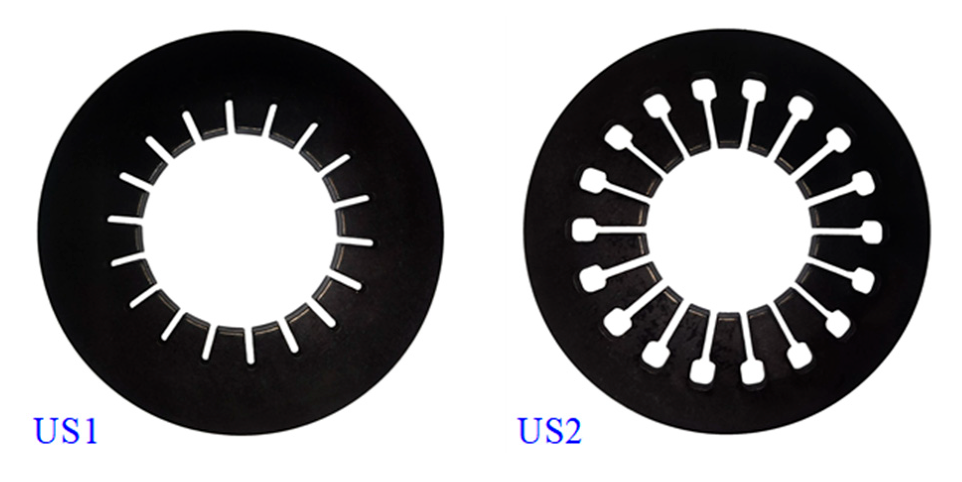
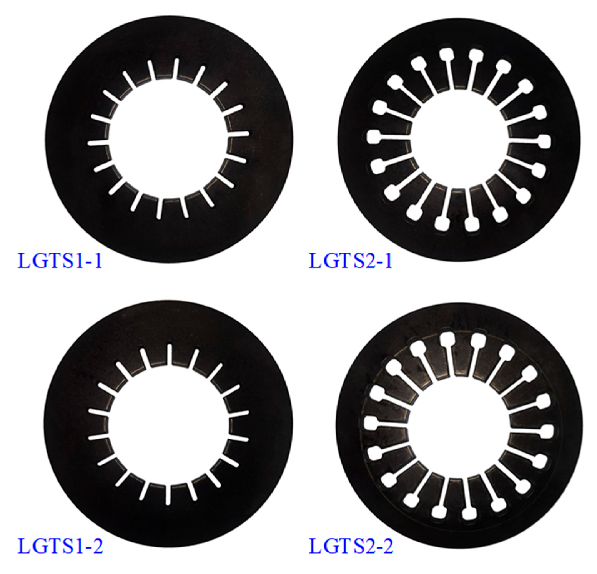
| Parameter | Symbol | US1 | US2 | LGTS1-1 | LGTS1-2 | LGTS2-1 | LGTS2-2 |
|---|---|---|---|---|---|---|---|
| Young’s modulus | E (MPa) | 206,000 | 206,000 | 20,600 | 20,600 | 206,000 | 206,000 |
| Poisson’s ratio | 0.3 | 0.3 | 0.3 | 0.3 | 0.3 | 0.3 | |
| Outer radius | (mm) | 75 | 75 | 75 | 75 | 75 | 75 |
| Inner radius | (mm) | 50 | 58 | 50 | 50 | 58 | 58 |
| Minimum inner radius | (mm) | 36 | 30 | 36 | 36 | 30 | 30 |
| Free height | (mm) | 4.1 | 3.2 | 4.1 | 4.4 | 3.2 | 2.8 |
| Thickness | (mm) | 6 | 6 | 6 | 6 | 6 | 6 |
| Thickness variation rate | 0 | 0 | −0.167 | −0.33 | −0.167 | −0.4 |
Disclaimer/Publisher’s Note: The statements, opinions and data contained in all publications are solely those of the individual author(s) and contributor(s) and not of MDPI and/or the editor(s). MDPI and/or the editor(s) disclaim responsibility for any injury to people or property resulting from any ideas, methods, instructions or products referred to in the content. |
© 2023 by the authors. Licensee MDPI, Basel, Switzerland. This article is an open access article distributed under the terms and conditions of the Creative Commons Attribution (CC BY) license (https://creativecommons.org/licenses/by/4.0/).
Share and Cite
Du, X.; Sun, Z. Modeling and Testing for Slotted Disk Springs Considering Linearly Gradient Thickness and Friction. Appl. Sci. 2023, 13, 11663. https://doi.org/10.3390/app132111663
Du X, Sun Z. Modeling and Testing for Slotted Disk Springs Considering Linearly Gradient Thickness and Friction. Applied Sciences. 2023; 13(21):11663. https://doi.org/10.3390/app132111663
Chicago/Turabian StyleDu, Xinxin, and Zengchun Sun. 2023. "Modeling and Testing for Slotted Disk Springs Considering Linearly Gradient Thickness and Friction" Applied Sciences 13, no. 21: 11663. https://doi.org/10.3390/app132111663
APA StyleDu, X., & Sun, Z. (2023). Modeling and Testing for Slotted Disk Springs Considering Linearly Gradient Thickness and Friction. Applied Sciences, 13(21), 11663. https://doi.org/10.3390/app132111663