Article

Research on the Residual Stress Field of a Compression Bushing-Lug Plate in Cold Expansion Strengthening

1
School of Mechatronics Engineering, Harbin Institute of Technology, Harbin 150001, China
2
Aerospace Precision Products Co., Ltd., Tianjin 300300, China
*
Author to whom correspondence should be addressed.
Appl. Sci. 2023, 13(21), 11694; https://doi.org/10.3390/app132111694
Submission received: 13 September 2023 / Revised: 7 October 2023 / Accepted: 20 October 2023 / Published: 26 October 2023

Abstract

:
The accurate acquisition of the residual stress field is the key to clarifying the cold expansion strengthening mechanism of compression bushings, optimizing the extrusion process parameters, and improving the structural fatigue life. In the actual cold expansion strengthening process, the resultant distribution of residual stresses is influenced by the relative extrusion amount, mandrel structure, material properties, and extrusion speed. In this article, the distribution patterns of residual stress after cold extrusion are investigated through a combination of finite element simulation and experimental measurements using a micro-region stress tester. To examine the redistribution law of the stress field of cold expansion reinforcement under external load, the compression bushing-lug-plate-reinforced structure is loaded and unloaded. The results show that large circumferential residual compressive stresses are distributed in the hole wall of the compression bushing after cold expansion. Radial residual stresses are also compressive stresses, although the values are small. In addition, the reinforced structure after cold extrusion presents a large difference in the stress redistribution rules compared with cold extrusion after the load is applied and removed.

1. Introduction

For advanced fighter jets and modern commercial aircraft, light weight and durability have become common goals for design and manufacturing engineers. The hole structure is widely used because it can realize the advantages of light equipment weight, reliable connection, and easy maintenance. Although the fastening holes serve to connect and transfer loads, the original structural and material continuity of the equipment device is disrupted [1,2,3]. Its service process is prone to the stress concentration phenomenon. Under alternating load, the whole wall will produce fatigue cracks or even fracture failure. Studies have shown that 50% to 90% of aircraft failures are attributed to the failure of hole structures, and fatigue damage has become the main form of damage to aircraft structures [4,5,6]. Therefore, improving the fatigue strength of the pore structure is essential to enhance the performance and prolong the life of the aircraft.
To enhance the fatigue life of the hole structure, the cold expansion strengthening technology of compression bushings is widely used [7,8,9,10]. It can reduce the hole edge stress under external load and effectively inhibit the crack generation at the hole edge [11,12,13]. Compression bushings have been massively applied to the fatigue strengthening of the important joints of many aircraft models at home and abroad [14,15]. The domestic academic system has invested a great deal of research in order to clarify the cold expansion strengthening mechanism. Lv et al. improved the fatigue life of fasteners by applying compressive residual stresses around their holes [16]. They used the finite element method (FEM) to study the distribution and variation of residual stresses around the hole. Additionally, they investigated the distribution and variation of residual stresses at the edge of the hole in the cold expansion specimens. Dey et al. found that increasing the yield strength of the aluminum workpiece and the percentage of expansion of the split sleeve cold expansion (SSCE) improved the hoop-oriented residual stresses around the cold-expanded holes [17]. However, the yield strength of the workpiece had a greater effect on the residual stress field. As the yield strength and expansion percentage of the workpiece increase, the process tension in the SSCE process also increases. Seifi et al. investigated the distribution of residual stresses generated during the cold expansion of two neighboring holes [18]. The results showed that parameters such as hole geometry, expansion ratio, and crack location affect the fatigue behavior. The effect of the expansion ratio varies compared to other parameters. The reduction in adjacent hole spacing decreases the total life and crack growth life. To quantify the distribution of residual stresses after cold expansion strengthening, many simulation methods have been proposed [19,20,21,22,23]. A comparison of the simulation results with experimental studies showed that the simplified simulation method could adequately predict the beneficial residual stresses around the holes due to cold expansion, including the residual stresses generated through thickness variations. Liu et al. developed a finite element model to investigate the residual stress field in cold-expanded holes and experimentally measured the residual stresses in cold-expanded holes to verify the simulation results [5]. The results show that the maximum values of circumferential residual compressive/tensile stresses in both the “infinite” and “finite” domains increase with the development of the interference values, and higher values of positive stresses are obtained at the boundary of the “finite” domain [24,25,26,27]. In addition to this, the main parameters affecting bushing repair can be analyzed qualitatively based on fatigue theory [28,29,30,31]. The results showed that the fatigue quality of the bushing decreases with the increase in the bushing’s outer diameter.
In the present study, cold expansion strengthening experiments and the finite element modeling of compression bushing-lug plates are executed. The distribution pattern of residual stresses after cold expansion under various relative expansions was investigated. Furthermore, the redistribution pattern of stress under external loading was explored. The influence of expansion parameters on the strengthening properties was also clarified. The strengthening law of cold extrusion was revealed. Theoretical support is provided for applying cold expansion strengthening technology to compression bushing-lug plates.

2. Materials and Methods

2.1. Finite Element Simulation Model

The pull-out of the mandrel in the cold expansion strengthening process of compression bushings is a relatively slow process, which can be treated as a quasi-static loading and unloading process in establishing the finite element model. Therefore, Standard, a static analysis module in ABAQUS 2019 software, can be the problem solver to establish a 3D finite element model for the cold expansion of compression bushings. To maximize the accuracy of the finite element analysis, hexahedral 20-node elements were selected. In the finite element analysis, SOLID186 solid elements were adopted to mesh the constructed model. The bushing component is the focus of this study, so the meshing of the bushing part is more dense. The mesh of the simulation model has been tested several times to avoid the sensitivity and dependence problem of mesh density in the simulation results. In order to improve the accuracy of mesh delineation and enhance the computational efficiency, a double symmetric model of 1/4 structure is established based on the symmetric structure of lug plates and compression bushings, as shown in Figure 1. First, the right-handed right-angle coordinate system is established. Finally, the assembly and mutual positions of the components before the initial expansion are defined. The intersection of the axis of the lug plate hole with the expansion surface is set to the origin of the coordinate system. The intersection of the symmetry plane in the length direction of the lug plates with the expansion plane is the X-axis, and the hole axis is the Z-axis. The loading variations are accomplished through the various extrusion amounts between the mandrel and the compression bushing. In this research, general extrusion amounts of 1.5% to 4% were examined and the higher extrusion amount of 4% was applied on the models. Before the cold extrusion simulation, the mandrel and lug sheet holes were set as master surfaces, while the inner and outer surfaces of the compression bushing were set as slave surfaces. Since most mandrels are pre-lubricated, the friction between the mandrels and the compression bushing could be omitted in the cold extrusion simulation. Instead, the installation of the compression bushing relied on the friction between the compression bushing and lug plate hole, so the friction coefficient of the contact pair between the compression bushing and lug plate hole was set to 0.1. During the simulation, all the degrees of freedom of the parts except the mandrel were fixed. This was to prevent the failure caused by the extrusion of the mandrel resulting in the follow-through of the other parts. The degrees of freedom of the mandrel along the axis were released, and the other degrees of freedom were fixed. As the mandrel moved along the axis, the tapered section of the mandrel gradually squeezed the bushing and lugs to implement the loading process.
Since the most important process in the cold expansion strengthening process of compression bushings is the axial pull-out process of the mandrel, the initial analysis step (initial) and the expansion analysis step (expansion) are mainly set up to establish the cold expansion strengthening model. In the initial analysis step, the positioning and initial contact of each component is completed. In the expansion analysis step, the mandrel expansion and gradual unloading of the bushing are carried out to realize the interference fit between the bushing and the lug plate. In addition, to further study the stress redistribution law of the reinforced structure under external loads, it is also necessary to set up the loading and unloading analysis step.

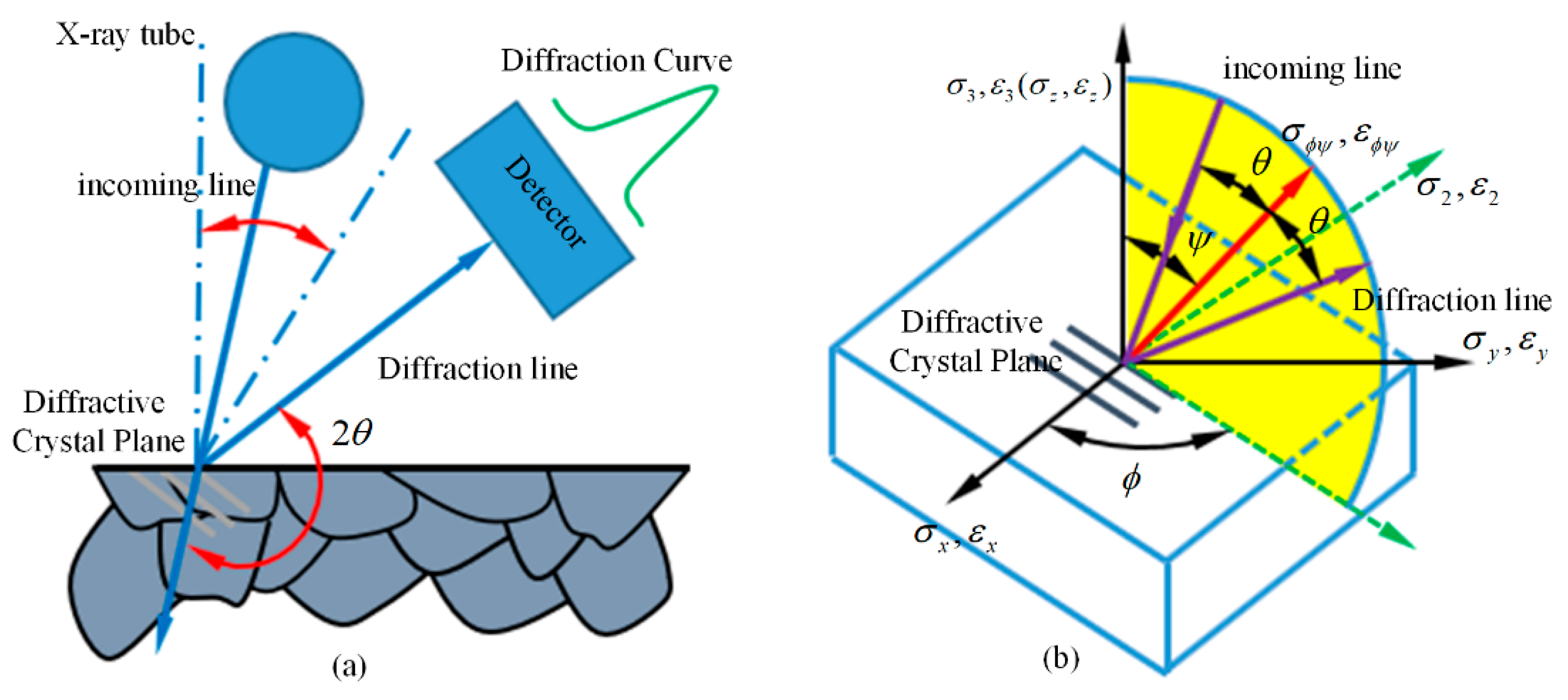
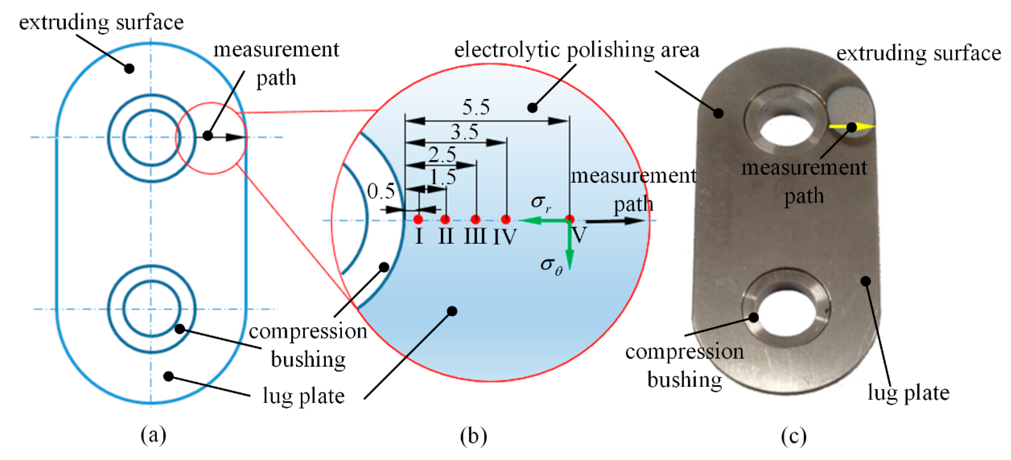
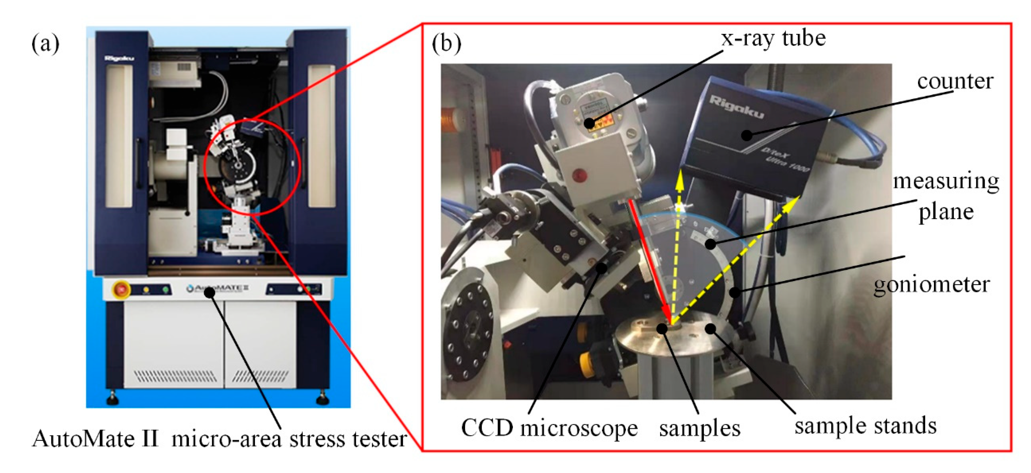
2.2. Experimental Principles and Equipment

During the cold extrusion experiment, the compacted assembly of bushing and lug is tightened in a vise to prevent the movement of the lugs. The equipment section of the mandrel is clamped through the bushing on a fixed pulling device. The extrusion of the mandrel bushing-lug subassembly is achieved with the contraction of the mandrel by the pulling device, which results in the application of the load. After the cold extrusion experiments, the mandrel is dismantled in reverse installation order. Then, the residual stress test of the lugs can be carried out. Figure 2a is a schematic diagram of the measurement of residual stresses in lug plates using X-ray diffraction, and the coordinate system for the determination of the X-ray diffraction method is shown in Figure 2b, where 2θ is the diffraction angle, and Ψ is the azimuthal angle normal to the diffracted crystal plane.
In summary, determining residual stresses on the surface of lug plates using X-ray diffraction is a matter of determining the diffraction angle at different azimuths and calculating it separately. The sample of this study is a reinforced structure after the expansion of compression bushing and lug plates, in which the material of the compression bushing is PH13-8Mo stainless steel and the material of the lug plates is TC4-DT titanium alloy. As the residual stress distribution of the reinforced structure of the compression bushing-lug plate, the stress state of the lug plate plays a decisive influence on the life of the entire reinforced structure, so this time, the main determination of the residual stress distribution is along the path of the TC4-DT titanium alloy lug plate. The modulus of elasticity of the TC4-DT titanium alloy lug plate is 109 GPa, and the Poisson’s ratio is 0.34.
In the preliminary pre-experiment and pre-simulation, as well as relevant references, it is known that the transition region between the rectangle and semicircle of the part is the region of maximum circumferential stress, so this region is selected for radial stress analysis. Moreover, the destruction of the bushing occurs first at the shaft end face, which is the location of the greatest axial stress. Figure 3a shows a schematic diagram of the location of the test point and the test direction of the sample. The stress measurement point was set as the direction of the extruded surface of the lug along the smallest cross-section in the figure. As to the residual stress in the thickness direction of the lug plate, it is usually determined by the geometrical requirement of the mechanical structure, which is lower than that at the shaft end face from the simulation results. Considering the experimental measurement and key issue of the application, the stress effect of the thickness direction is neglected in the simulation. The distances of the measurement points from the aperture wall of the lug plate were 0.5 mm, 1.5 mm, 2.5 mm, 3.5 mm, and 5.5 mm, respectively, and the radial and circumferential stresses were measured at each measurement point, as shown in Figure 3b. Figure 3c shows a sample of a lug plate of titanium alloy material determined in this study. The area to be determined was electrolytically polished to reduce the degree of influence of surface machining on the determination of cold expansion residual stresses.
Currently, there are many techniques used for stress measurement, among which X-ray diffraction is the most used in high-precision measurement methods [32], so X-ray diffraction equipment was also chosen for this experiment. The AutoMate II high-power micro-area stress tester from Rigaku, Japan, was used to determine residual stresses in lug plates. Figure 4 shows the equipment used in this residual stress measurement and the sample determination process. Since the effective depth of penetration of X-rays on metal surfaces is usually small, the values of residual stresses are strongly influenced by the surface condition. The surface of the measurement area of the sample must be suitably treated before measurement using X-ray diffraction. Before this measurement, alcohol was used to remove surface oil and dirt, and diluted hydrochloric acid was used to remove oxidized skin and rust spots further to reveal a bright metal surface. Subsequently, small-current-density electrolytic polishing was used to carry out short-term localized surface treatment on the measurement area of the samples, and the samples were cleaned and dried on time after polishing.
The Cu target rays were selected to measure residual stress in TC4 titanium alloy lug plates. According to the test-diffracted intensity profile, the appropriate tube voltage and current were selected to ensure that the particle counter could obtain sufficient ray intensity. The diffraction angle is a key parameter to determine the clarity of the diffraction pattern, and it was determined based on the pre-experiment that the diffraction angle chosen for this measurement was 140°. The specific measurement conditions for the stress testing process are shown in Table 1.

3. Results and Analysis

3.1. Finite Element Simulation Results

Figure 5 shows the finite element results of the stresses in the TC4-DT titanium alloy lug plate and compression bushing expansion. The results in Figure 5 show that the compression bushing mainly exists in the form of compressive stresses, while the lug plates mainly show tensile stresses, and the maximum compressive stress area is near the hole wall of the compression bushing along the width of the lug. This is mainly because, during the cold extrusion strengthening process, in addition to the extrusion process of the bushing and lugs with the conical section of the mandrel, there is also a slight pulling process due to the movement of the mandrel along the axial direction. As a result, the lug can show tensile stresses in the form of transition under the bushing. Along the path of the extruded surface, S11 is plotted as a function of the distance from the lug plate hole wall. Along the path of the extruded surface, S11 is plotted as a function of the distance from the lug plate hole wall. The circumferential stresses gradually increase with distance from the lug sheet aperture wall, forming tensile stresses. The residual stress at the lug sheet aperture wall is about zero, and the residual tensile stress at the edge is about 350 MPa. In contrast to the pattern presented by the annular stresses, the radial stress curves generally show a decreasing and then increasing trend. However, as the distance from the lug plate hole increases, the radial compressive stress values tend to increase and then decrease. The compressive stress reaches its maximum value of about 225 MPa at 1.5 mm from the wall of the lug plate.

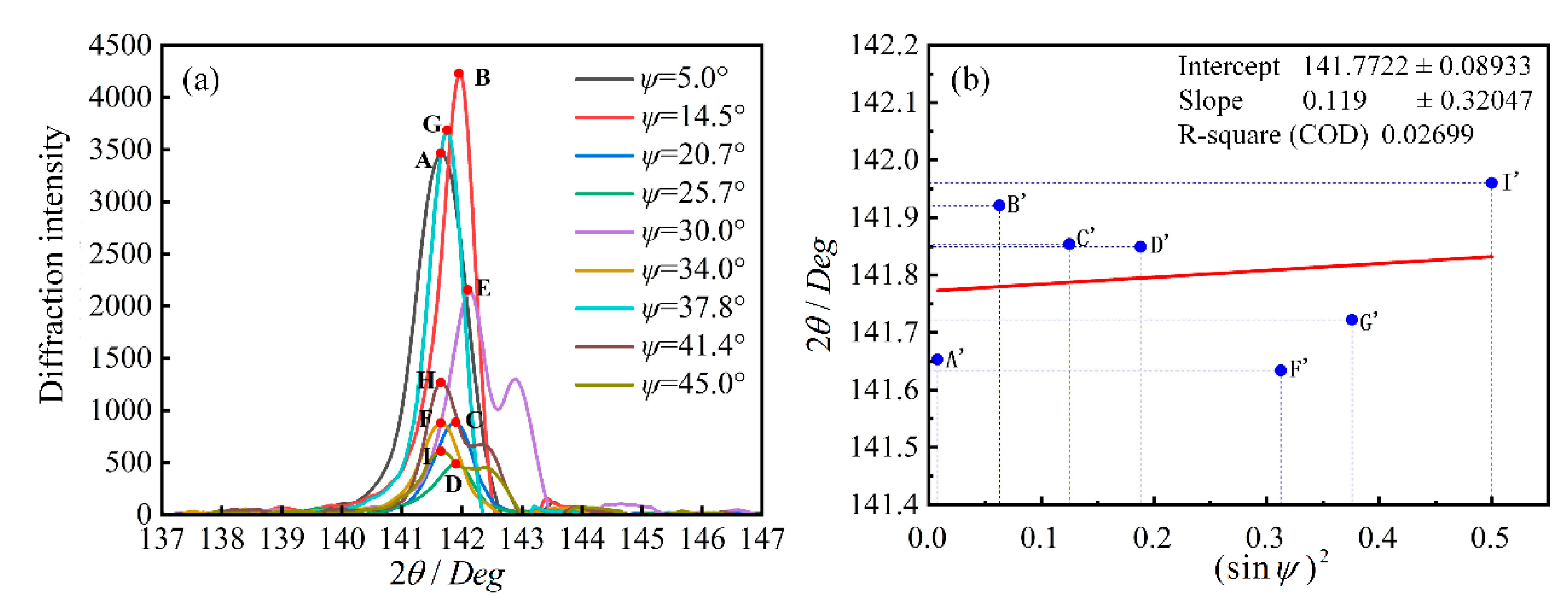
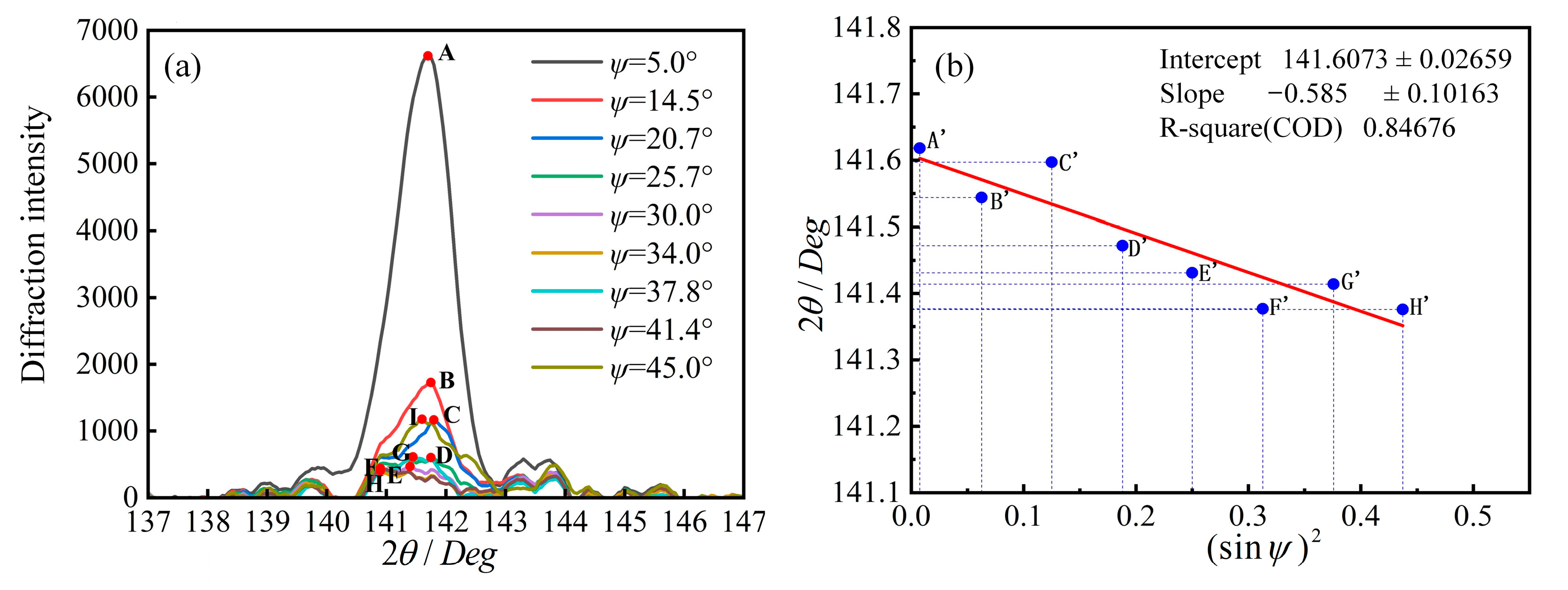
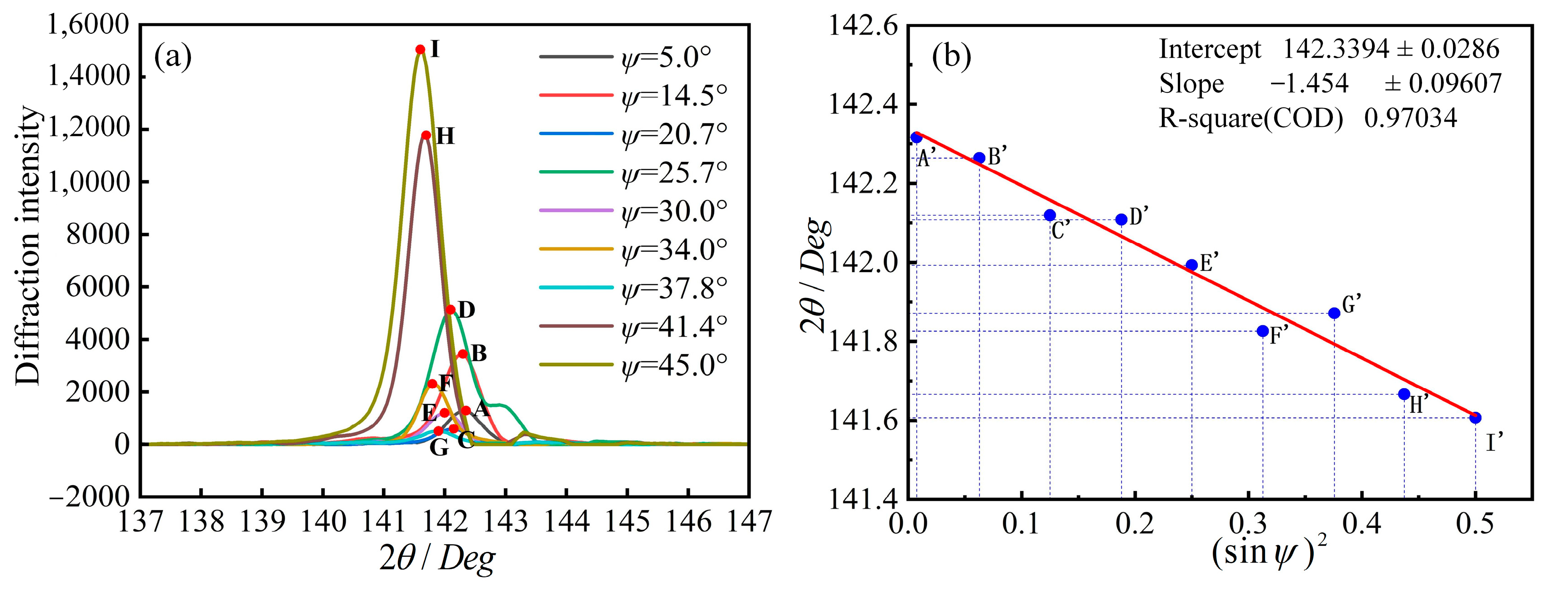
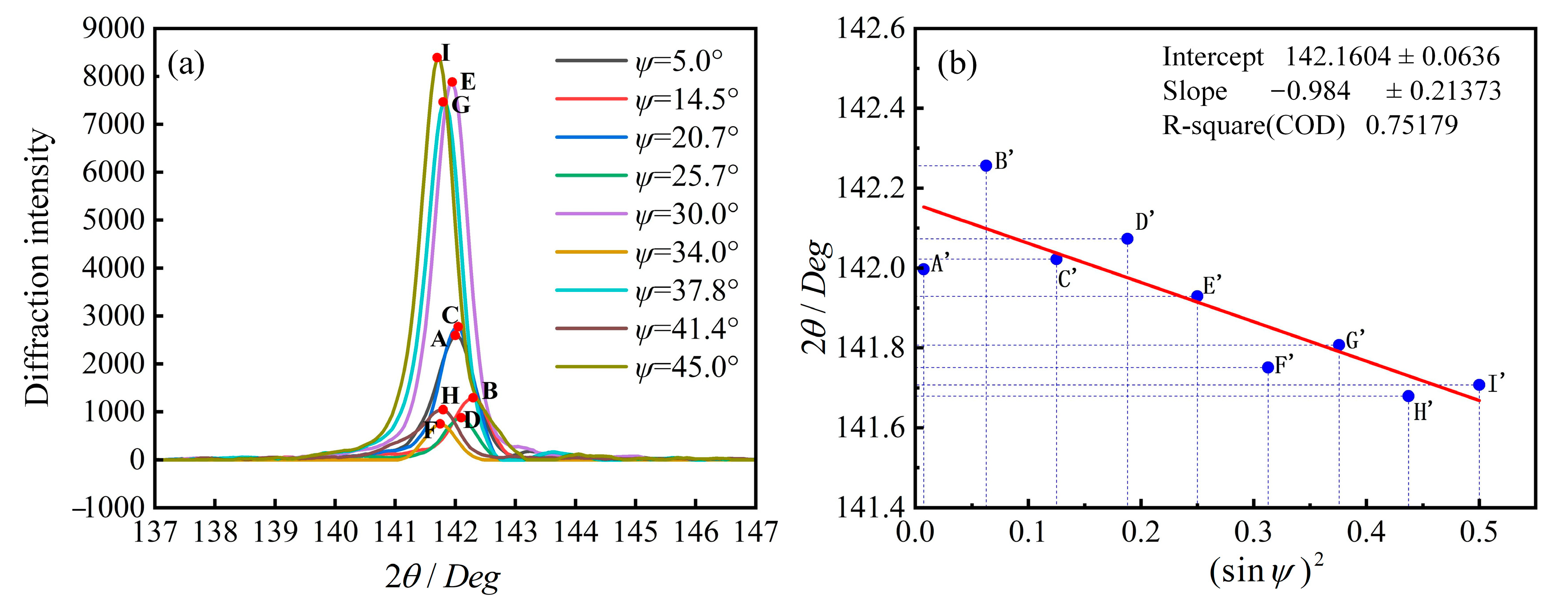
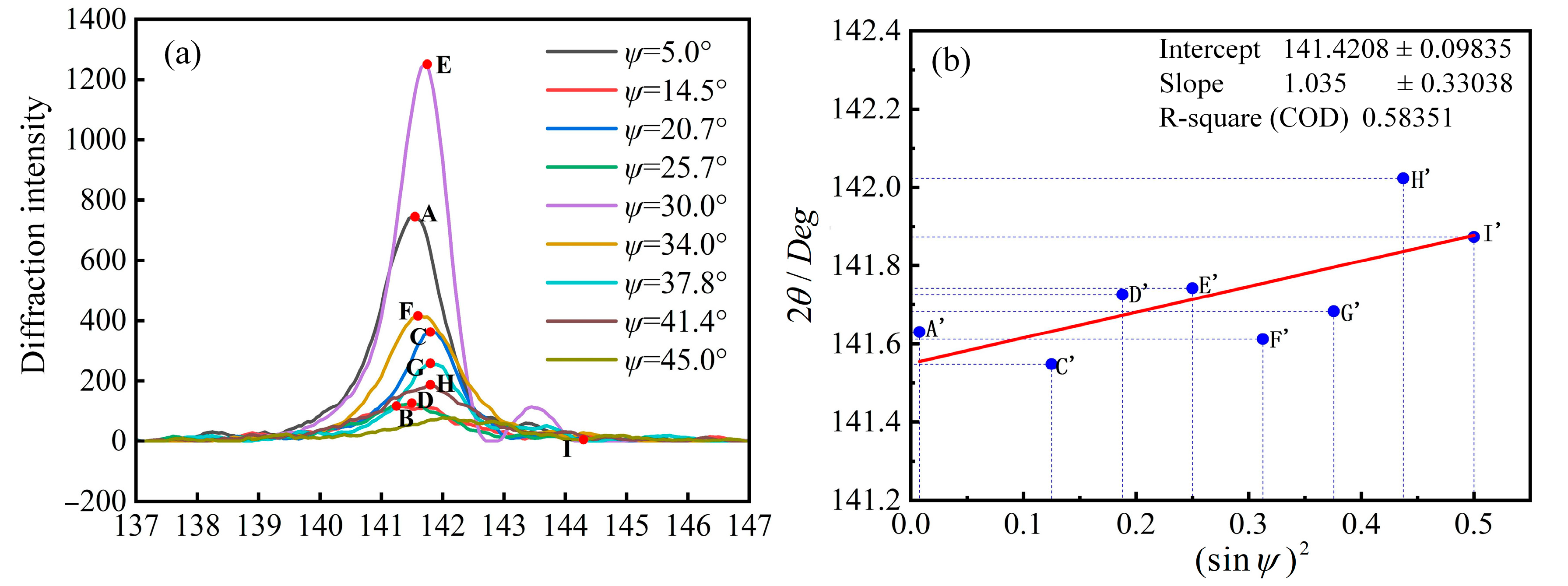
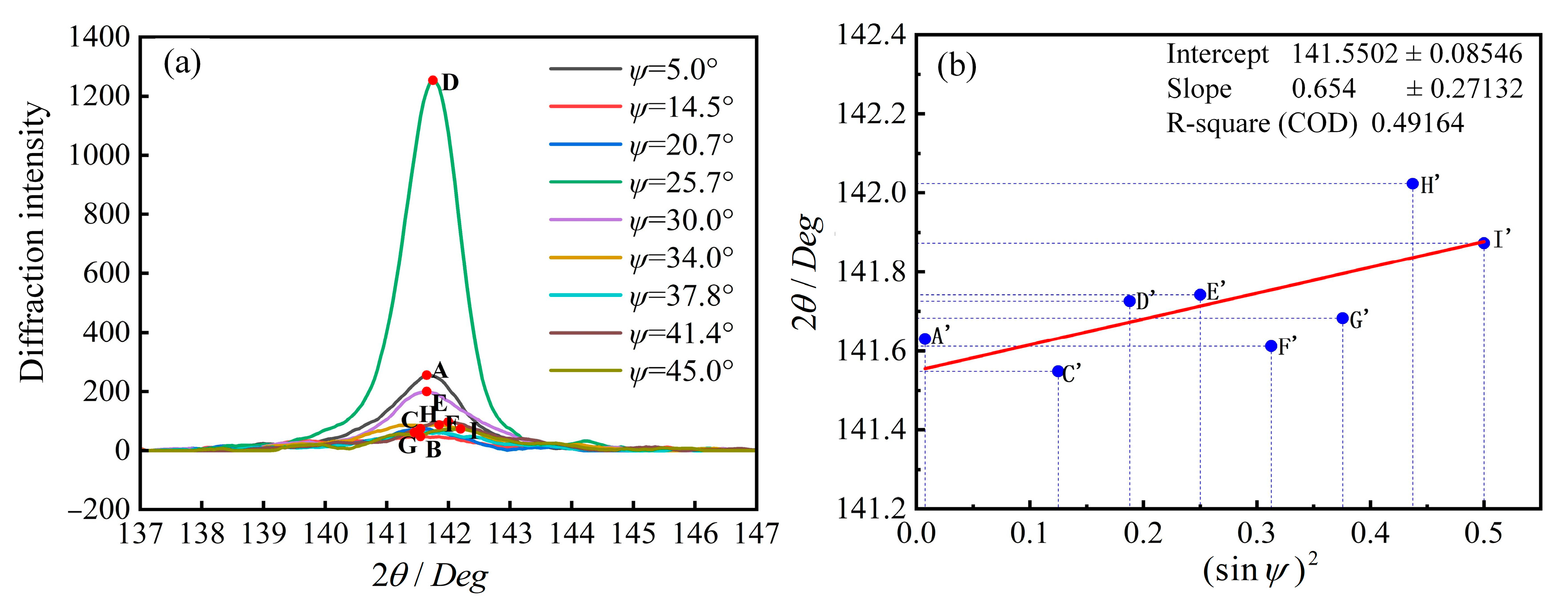
3.2. Raw Data Processing of Circumferential Stresses

Since the initial diffracted intensity curves obtained using the X-ray diffraction method are not processed accordingly, the curves have a high degree of fluctuation and contain much prominence. This interferes with the search for the diffracted intensity peaks and their corresponding diffraction angles, and the back-bottom of the diffraction peaks is caused by factors unrelated to the Bragg diffraction used for the measurement, so it is necessary to subtract the back-bottom from the initial diffracted intensity curves and to smooth the data.
The initial diffracted intensity curves were processed via data deduction back-bottoming and smoothing using Jade 6.0 software. The diffracted intensity curves of the circumferential stress at different azimuth angles for each detection point were obtained as shown in Figure 6a, Figure 7a, Figure 8a, Figure 9a and Figure 10a. The x axis 2θ is the diffraction angle and Ψ denotes the azimuthal angle. The y axis denotes the diffraction intensity and the diffraction angle separately. The diffraction angle corresponding to the peak value of each diffraction intensity curve at different azimuth angles was taken as the function value, and the fitted straight line between the corresponding diffraction angle and the sine square of the azimuth angle at each detection point was made, as shown in Figure 6, Figure 7, Figure 8, Figure 9 and Figure 10. At the beginning, the X diffraction pattern was not stable, so the coefficient of determination of the fitted curve was small, as shown in Figure 6b. However, as the experiment proceeded, the X diffraction pattern was gradually stabilized, and the coefficient of determination of the fitted curve was greater than 0.69 and reached 0.97 under the stable conditions, as shown in Figure 9b.
According to the diffraction angle and azimuth angle sine square of the fitting line, and then using the modulus of elasticity and Poisson’s ratio material parameters of the TC4 lug plate samples, the X-ray diffraction method was used to calculate the radial stress main data, which are listed in Table 2.

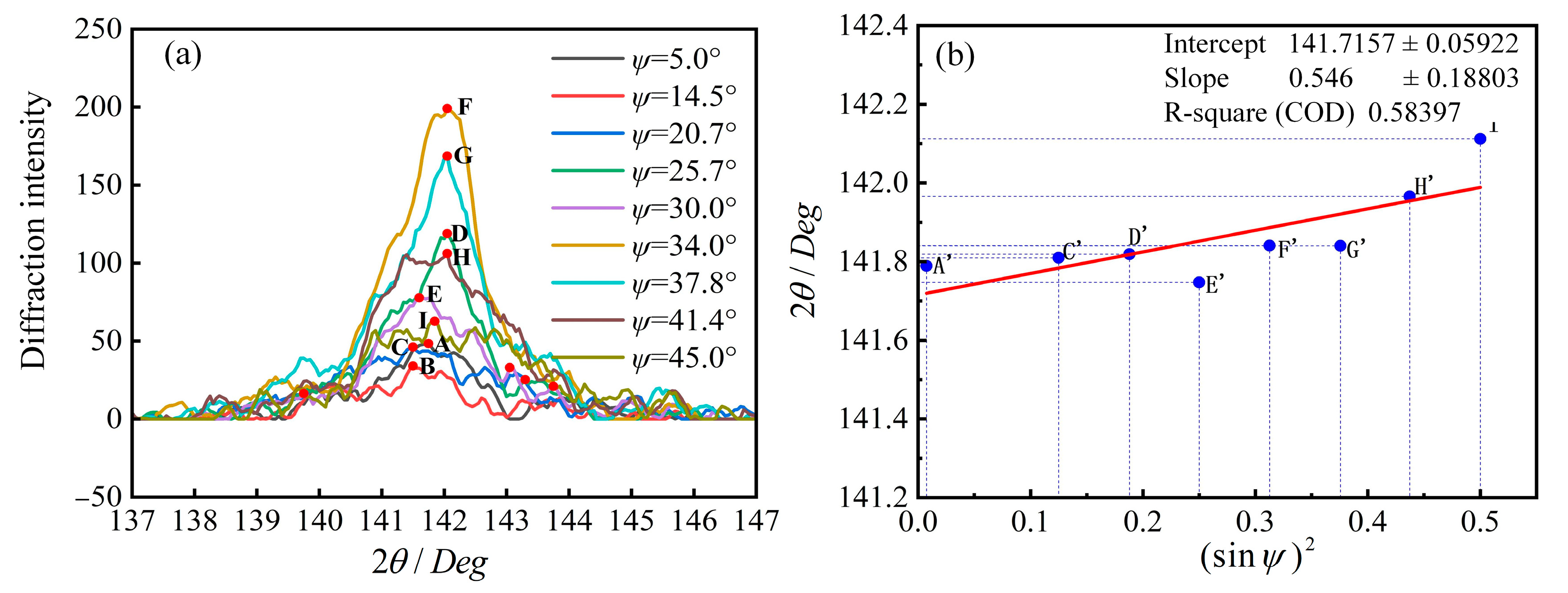
3.3. Raw Data Processing of Radial Stresses

The radial stress on the extruded face of the lug plate can be obtained using the following the method described in the whole text. Figure 11, Figure 12, Figure 13, Figure 14 and Figure 15 show the diffraction intensity curves at different azimuth angles for each detection point. According to the slope and intercept of the fitted straight line with the diffraction angle and azimuth angle sine squared, and then using the modulus of elasticity and Poisson’s ratio material parameters of the TC4 lug plate sample, the radial residual stress values distributed along the specified paths on the extruded surface of the lug plate after cold expansion were obtained, and the main data of the radial stress calculated using the X-ray diffraction method are listed in Table 3.

3.4. Verification of the Residual Stress Test Results

The annular and radial stresses on the extruded surface of the lugs along the specified paths were determined experimentally using the X-ray diffraction method. The residual stress distribution pattern of the compression bushing-lug plate after the cold expansion of the compression bushing was obtained using finite element simulation. The comparison curves of the experimental and simulation results for the circumferential and radial stresses are shown in Figure 16. Both material and operating conditions can have a significant effect on the stresses, so the curve in Figure 16 is only applicable to the stress conditions of this study. The four curves in Figure 16 represent the finite element simulation results and experimental measurements of the circumferential and radial stresses, respectively. With the results of circumferential stress, the finite element results are very close to the experimental measurements at a closer distance from the hole wall. When the distance from the hole wall is far, the experimental determination of stress results will have some deviation from the simulation results due to the interference of external factors. However, in determining radial stress, the experimental results are in good agreement with the finite element simulation results, and both results have the phenomenon of reverse yielding in the tested distance limitation range from hole wall. The environmental factors in the experiment are complex, while the simulation is an ideal condition, so the results of the experiment and the simulation cannot be completely consistent [33]. But, the changing trends of the curves are consistent, and the results of the experiment can validate the simulation results.
Combining the finite element simulation results and experimental measurements of the circumferential and radial stresses, both the circumferential and radial stresses, the finite element simulation results are very close to the results of the X-ray diffraction measurements. Thus, the experimental measurements based on the residual stresses verify the accuracy of the finite element simulation results.

4. Conclusions

In this paper, the structural residual stress field distribution after cold expansion was obtained based on finite element simulation and X-ray diffraction method, respectively. The influence law of the residual stress distribution state under different cross-section paths was obtained by altering the relative squeezing amount. In addition, the stress redistribution law of the structure under external load was also investigated. The specific results are as follows:
(1)
After cold expansion, large annular residual compressive stresses are distributed in the hole wall of the compression bushing, while the radial residual stresses also exist in the form of compressive stresses but with smaller values. The distribution of circumferential and radial stresses varies considerably on the expansion face, the intermediate face, and along the hole axis, and the increase in the relative expansion exacerbates the inhomogeneity of this distribution.
(2)
Compared to the hole structure without extrusion strengthening, the maximum circumferential stress on the hole wall of the hole structure after cold extrusion is significantly reduced during loading. The higher relative extrusion amount can effectively reduce the amplitude of annular stress on the hole wall, thereby improving fatigue life.
(3)
Combined with the X-ray diffraction method, the measured values of annular stress and radial stress distributed along the path of hazardous cross-section on the extruded surface of the lug plate after cold expansion were obtained. After comparing these with the simulation results obtained from the finite element model, it was found that experimental and simulation values were in good agreement, which verified the accuracy of the finite element results of the residual stresses.
This study provides theoretical support for the application of compression bushings in engineering. The fatigue life of compression bushings in complex loading applications can be investigated further for a new perspective.

Author Contributions

Conceptualization, Z.L.; methodology, Z.L.; software, Z.L.; validation, Z.L.; formal analysis, H.W.; investigation, H.W.; resources, Q.B.; data curation, B.W.; writing—original draft preparation, B.W.; writing—review and editing, H.W.; visualization, B.W.; writing—review and editing, W.L.; software, W.L.; supervision, W.L.; project administration, Q.B.; funding acquisition, Q.B. All authors have read and agreed to the published version of the manuscript.

Funding

This research received no external funding.

Institutional Review Board Statement

Not applicable.

Informed Consent Statement

Not applicable.

Data Availability Statement

Not applicable.

Conflicts of Interest

Wensheng Li was employed by Aerospace Precision Products Co., Ltd. The remaining authors declare that the research was conducted in the absence of any commercial or financial relationships that could be construed as a potential conflict of interest.

References

  1. Yang, K.; Chen, X.; Lv, X.; Ding, F.; Dang, B.; Li, F.; Wei, D.; Zhang, P. Effect of split-sleeve cold hole expansion on the fatigue performance of an additive manufactured TC18 alloy. J. Mater. Res. 2023, 38, 841–852. [Google Scholar] [CrossRef]
  2. Hu, J.; Mi, S.; Yang, Z.; Wang, C.; Yang, Y.; Tian, W. An experimental investigation on bearing behavior and failure mechanism of bolted composite interference-fit joints under thermal effects. Eng. Fail. Anal. 2022, 131, 105830. [Google Scholar] [CrossRef]
  3. Liu, H.; Hu, D.; Wang, R.; Wang, X.; Jin, S.; Gu, Y. Experimental and numerical investigations on the influence of cold expansion on low cycle fatigue life of bolt holes in aeroengine superalloy disk at elevated temperature. Int. J. Fatigue 2020, 132, 105390. [Google Scholar] [CrossRef]
  4. Faghih, S.; Behravesh, S.B.; Kumar Shaha, S.; Jahed, H. Effect of split sleeve cold expansion on fatigue and fracture of rolled AZ31B magnesium alloy. Theor. Appl. Fract. Mech. 2023, 123, 103715. [Google Scholar] [CrossRef]
  5. Liu, J.; Xu, H.L.; Zhai, H.B.; Yue, Z.F. Effect of detail design on fatigue performance of fastener hole. Mater. Des. 2010, 31, 976–980. [Google Scholar] [CrossRef]
  6. Wang, C.; Zou, F.; Zhou, E.; Fan, Z.; Ge, E.; An, Q.; Ming, W.; Chen, M. Effect of split sleeve cold expansion on microstructure and fatigue performance of 7075-T6 aluminum alloy holes. Int. J. Fatigue 2023, 167, 107339. [Google Scholar] [CrossRef]
  7. Özdemir, A.T. Experimental assessment of the redistribution of 3-D residual stresses during early fatigue at split-sleeve cold expanded reamed A/C fastener holes. Sci. Iran. 2017, 25, 1153–1168. [Google Scholar] [CrossRef]
  8. Karparvarfard, S.; Shaha, S.K.; Behravesh, S.B.; Jahed, H.; Williams, B.W. Fatigue characteristics and modeling of cast and cast-forged ZK60 magnesium alloy. Int. J. Fatigue 2019, 118, 282–297. [Google Scholar] [CrossRef]
  9. Aid, A.; Semari, Z.; Benguediab, M. Cold expansion effect on the fatigue crack growth of Al 6082: Numerical investigation. Struct. Eng. Mech. 2014, 49, 225–235. [Google Scholar] [CrossRef]
  10. Chakherlou, T.N.; Taghizadeh, H.; Aghdam, A.B. Experimental and numerical comparison of cold expansion and interference fit methods in improving fatigue life of holed plate in double shear lap joints. Aerosp. Sci. Technol. 2013, 29, 351–362. [Google Scholar] [CrossRef]
  11. Curto-Cárdenas, D.; Calaf-Chica, J.; Bravo Díez, P.M.; Preciado Calzada, M.; Garcia-Tarrago, M.-J. Cold Expansion Process with Multiple Balls-Numerical Simulation and Comparison with Single Ball and Tapered Mandrels. Materials 2020, 13, 5536. [Google Scholar] [CrossRef] [PubMed]
  12. Yan, W.Z.; Wang, X.S.; Gao, H.S.; Yue, Z.F. Effect of split sleeve cold expansion on cracking behaviors of titanium alloy TC4 holes. Eng. Fract. Mech. 2012, 88, 79–89. [Google Scholar] [CrossRef]
  13. Yuan, X.; Yue, Z.F.; Wen, S.F.; Li, L.; Feng, T. Numerical and experimental investigation of the cold expansion process with split sleeve in titanium alloy TC4. Int. J. Fatigue 2015, 77, 78–85. [Google Scholar] [CrossRef]
  14. Liu, X.; Cui, H.; Zhang, S.; Liu, H.; Liu, G.; Li, S. Experimental and numerical investigations on fatigue behavior of aluminum alloy 7050-T7451 single lap four-bolted joints. J. Mater. Sci. Technol. 2018, 34, 1205–1213. [Google Scholar] [CrossRef]
  15. Wan, N.; He, Q.; Jing, X.; Jiang, Y.; Zhou, H. Numerical and experimental investigation of the effect of cold extrusion process on residual stress and fatigue life of internal thread of high-strength steel. Int. J. Adv. Manuf. Technol. 2023, 127, 4713–4726. [Google Scholar] [CrossRef]
  16. Lv, Y.; Dong, M.; Zhang, T.; Wang, C.; Hou, B.; Li, C. Finite Element Analysis of Split Sleeve Cold Expansion Process on Multiple Hole Aluminum Alloy. Materials 2023, 16, 1109. [Google Scholar] [CrossRef]
  17. Dey, M.K.; Kim, D.; Tan, H. Finite element parametric study of the split sleeve cold expansion on residual stresses and pulling force. Proc. Inst. Mech. Eng. Part C J. Mech. Eng. Sci. 2022, 236, 2447–2461. [Google Scholar] [CrossRef]
  18. Seifi, R. Total fatigue lives, crack growth paths and cycles in cold expanded adjacent holes. Int. J. Fatigue 2018, 113, 69–77. [Google Scholar] [CrossRef]
  19. Bueckner, H.F. Novel principle for the computation of stress intensity factors. Z. Fuer. Angew. Math. Mech. 1970, 50, 9. [Google Scholar]
  20. Moftakhar, A.A.; Glinka, G. Calculation of stress intensity factors by efficient integration of weight functions. Eng. Fract. Mech. 1992, 43, 749–756. [Google Scholar] [CrossRef]
  21. Vagarali, S.S.; Langdon, T.G. Deformation mechanisms in h.c.p. metals at elevated temperatures—II. Creep behavior of a Mg-0.8% Al solid solution alloy. Acta Metall. 1982, 30, 1157–1170. [Google Scholar] [CrossRef]
  22. Su, M.; Amrouche, A.; Mesmacque, G.; Benseddiq, N. Numerical study of double cold expansion of the hole at crack tip and the influence on the residual stresses field. Comput. Mater. Sci. 2008, 41, 350–355. [Google Scholar] [CrossRef]
  23. Kumar, B.M.; Panaskar, N.J.; Sharma, A. A fundamental investigation on rotating tool cold expansion: Numerical and experimental perspectives. Int. J. Adv. Manuf. Technol. 2014, 73, 1189–1200. [Google Scholar] [CrossRef]
  24. Sangid, M.D. The physics of fatigue crack initiation. Int. J. Fatigue 2013, 57, 58–72. [Google Scholar] [CrossRef]
  25. Liu, J.; Wu, H.; Yang, J.; Yue, Z. Effect of edge distance ratio on residual stresses induced by cold expansion and fatigue life of TC4 plates. Eng. Fract. Mech. 2013, 109, 130–137. [Google Scholar] [CrossRef]
  26. Semari, Z.; Aid, A.; Benhamena, A.; Amrouche, A.; Benguediab, M.; Sadok, A.; Benseddiq, N. Effect of residual stresses induced by cold expansion on the crack growth in 6082 aluminum alloy. Eng. Fract. Mech. 2013, 99, 159–168. [Google Scholar] [CrossRef]
  27. Stephen, G.J.; Pasang, T.; Withy, B.P. The effect of pitting corrosion on split sleeve cold hole expanded, bare 7075-T651 aluminium alloy. J. Manuf. Process. 2013, 15, 115–120. [Google Scholar] [CrossRef]
  28. Kim, H.K.; Carlson, S.S.; Stanfield, M.L.; Paddea, S.; Hosseinzadeh, F.; Bouchard, P.J. Mitigating Cutting-Induced Plasticity Errors in the Determination of Residual Stress at Cold Expanded Holes Using the Contour Method. Exp. Mech. 2022, 62, 3–18. [Google Scholar] [CrossRef]
  29. Liu, K.; Yang, X.; Zhou, L.; Li, M.; Zhu, W. Numerical investigation of the effect of hole reaming on fatigue life by cold expansion. Trans. Can. Soc. Mech. Eng. 2022, 46, 400–411. [Google Scholar] [CrossRef]
  30. Geng, H.; Xu, X.; Cao, Q.; Lai, Z.; Li, L. Improving the fatigue performance of AZ31 sheet with hole via electromagnetic cold expansion process. Int. J. Adv. Manuf. Technol. 2022, 120, 5057–5071. [Google Scholar] [CrossRef]
  31. Zeng, C.; Tian, W.; Liu, X.Y.; Xue, J.T. Experimental and numerical studies of stress/strain characteristics in riveted aircraft lap joints. J. Mech. Sci. Technol. 2019, 33, 3245–3255. [Google Scholar] [CrossRef]
  32. Guo, J.; Fu, H.; Pan, B.; Kang, R. Recent progress of residual stress measurement methods: A review. Chin. J. Aeronaut. 2021, 34, 54–78. [Google Scholar] [CrossRef]
  33. Fang, Z.-C.; Wu, Z.-L.; Huang, C.-G.; Wu, C.-W. Review on residual stress in selective laser melting additive manufacturing of alloy parts. Opt. Laser Technol. 2020, 129, 106283. [Google Scholar] [CrossRef]
Figure 1. Cold expansion structure, finite element lug, and compression bushing model. (a) Schematic diagram of cold expansion strengthening. (b) Finite element model.
Applsci 13 11694 g001
Figure 2. Principle of X-ray diffraction method for measuring residual stresses in lug plates. (a) Schematic diagram of the X-ray diffraction method for measuring residual stresses in a lug plate. (b) Determination of the coordinate system for the X-ray diffraction method.
Applsci 13 11694 g002
Figure 3. Schematic diagram of the sample residual stress detection position and direction. (a) Schematic diagram of the location and direction of the detection point. (b) Local enlargement. (c) Physical picture of the test sample.
Applsci 13 11694 g003
Figure 4. Residual stress testing equipment and sample measurement process. (a) The AutoMate II high-power micro-area stress tester. (b) Local enlargement.
Applsci 13 11694 g004
Figure 5. The finite element results of the extruded annular stress of C4-DT titanium alloy lug plate and compression bushing. (a) Stress map. (b) Stress curve.
Applsci 13 11694 g005
Figure 6. Raw data of annular stress at detection point I. (a) Diffraction intensity profiles at different azimuth angles. (b) Straight lines fitting the diffraction angle to the azimuthal angle.
Applsci 13 11694 g006
Figure 7. Raw data of annular stress at detection point II. (a) Diffraction intensity profiles at different azimuth angles. (b) Straight lines fitting the diffraction angle to the azimuthal angle.
Applsci 13 11694 g007
Figure 8. Raw data of annular stress at detection point III. (a) Diffraction intensity profiles at different azimuth angles. (b) Straight lines fitting the diffraction angle to the azimuthal angle.
Applsci 13 11694 g008
Figure 9. Raw data of annular stress at detection point IV. (a) Diffraction intensity profiles at different azimuth angles. (b) Straight lines fitting the diffraction angle to the azimuthal angle.
Applsci 13 11694 g009
Figure 10. Raw data of annular stress at detection point V. (a) Diffraction intensity profiles at different azimuth angles. (b) Straight lines fitting the diffraction angle to the azimuthal angle.
Applsci 13 11694 g010
Figure 11. Raw data of radial stress at detection point I. (a) Diffraction intensity profiles at different azimuth angles. (b) Straight lines fitting the diffraction angle to the azimuthal angle.
Applsci 13 11694 g011
Figure 12. Raw data of radial stress at detection point II. (a) Diffraction intensity profiles at different azimuth angles. (b) Straight lines fitting the diffraction angle to the azimuthal angle.
Applsci 13 11694 g012
Figure 13. Raw data of radial stress at detection point III. (a) Diffraction intensity profiles at different azimuth angles. (b) Straight lines fitting the diffraction angle to the azimuthal angle.
Applsci 13 11694 g013
Figure 14. Raw data of radial stress at detection point IV. (a) Diffraction intensity profiles at different azimuth angles. (b) Straight lines fitting the diffraction angle to the azimuthal angle.
Applsci 13 11694 g014
Figure 15. Raw data of radial stress at detection point V. (a) Diffraction intensity profiles at different azimuth angles. (b) Straight lines fitting the diffraction angle to the azimuthal angle.
Applsci 13 11694 g015
Figure 16. Comparison between finite element results and experimentally determined residual stresses.
Applsci 13 11694 g016
Table 1. Residual stress determination conditions.
Type Parameter
Voltage40 kV
Current40 mA
Crystal structureHexagonal
Diffraction crystal plane{213}
Diffraction angle140°
Oscillation setting
Exposure time100 s
Collimator diameter1 mm
Peaking methodHalf height and width method
Table 2. Main data of radial stress calculated using the X-ray diffraction method.
Detection Point 2 θ 0 (Deg) 2 θ 0 sin 2 ψ Stress Constant
(MPa/Deg)
Radial Stress (MPa)
I141.7720.119−246.003−29.274
II141.607−0.585−247.149144.582
III142.131−0.992−243.515241.567
IV142.339−1.454−242.076351.979
V142.160−0.984−243.314239.421
Table 3. Main data of radial stress calculation using the X-ray diffraction method.
Detection Point 2 θ 0 (Deg) 2 θ 0 sin 2 ψ Stress Constant
(MPa/Deg)
Radial Stress (MPa)
I141.6520.678−246.836−167.355
II141.4211.035−248.441−257.136
III141.5500.654−247.545−161.894
IV141.7160.546−246.392−134.530
V141.7610.359−246.080−88.343
Disclaimer/Publisher’s Note: The statements, opinions and data contained in all publications are solely those of the individual author(s) and contributor(s) and not of MDPI and/or the editor(s). MDPI and/or the editor(s) disclaim responsibility for any injury to people or property resulting from any ideas, methods, instructions or products referred to in the content.

