


Autonomous Process Execution Control Algorithms of Solid Intelligent Backfilling Technology: Development and Numerical Testing


Abstract
:1. Introduction
2. Design for Solid Intelligent Backfilling Mining Process
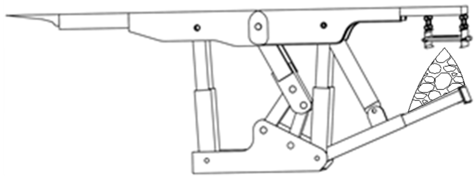
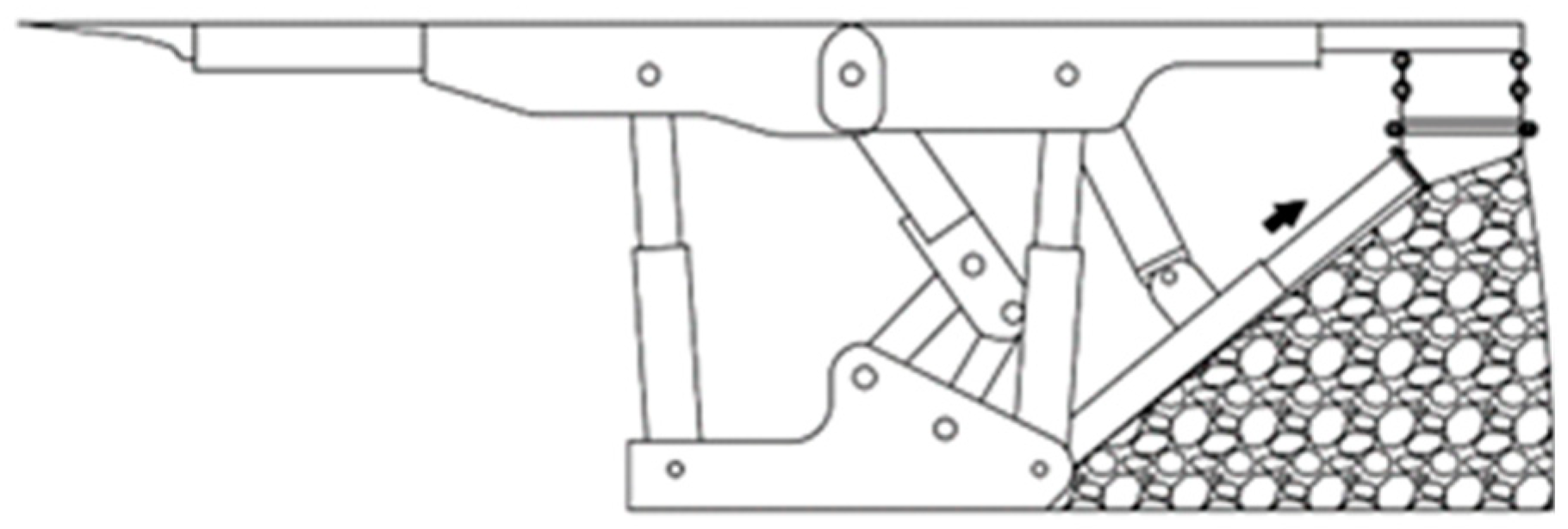
2.1. Issues in the Execution of Dumping and Tamping Process
2.2. The Solution for the Interference of Dumping and Tamping Processes
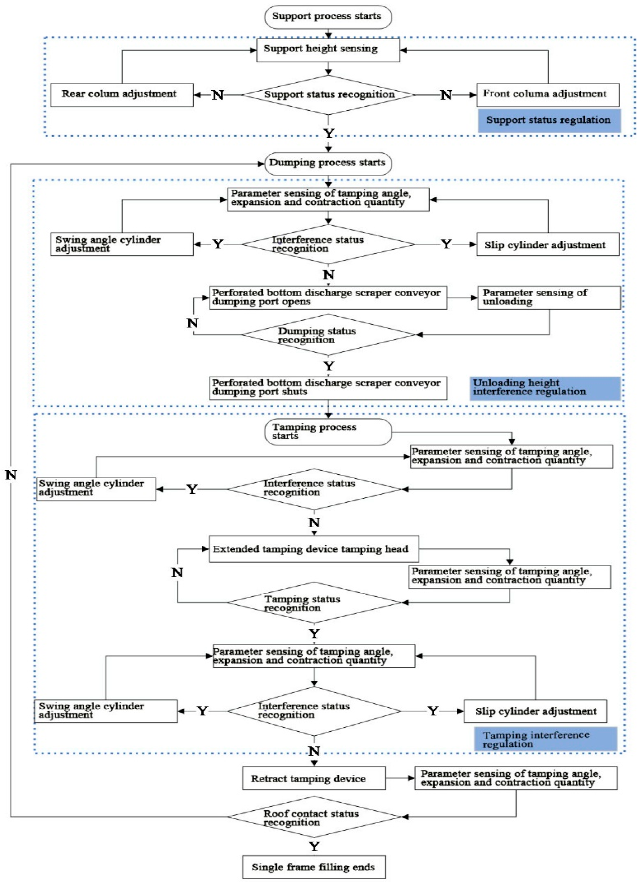
3. Interference Automatic Recognition and Tamping Path Planning
3.1. Interference Criticality Solving and Interference Automatic-Recognition Method
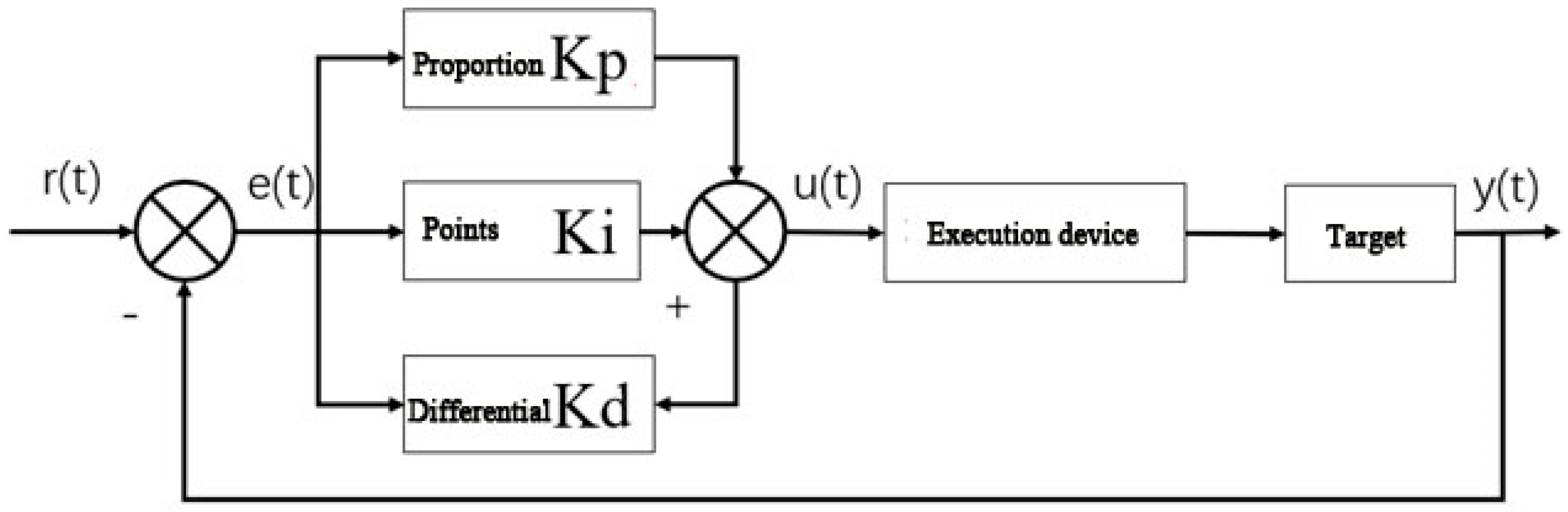
3.2. Automatic Control of the Tamping Device Hydraulic Cylinder
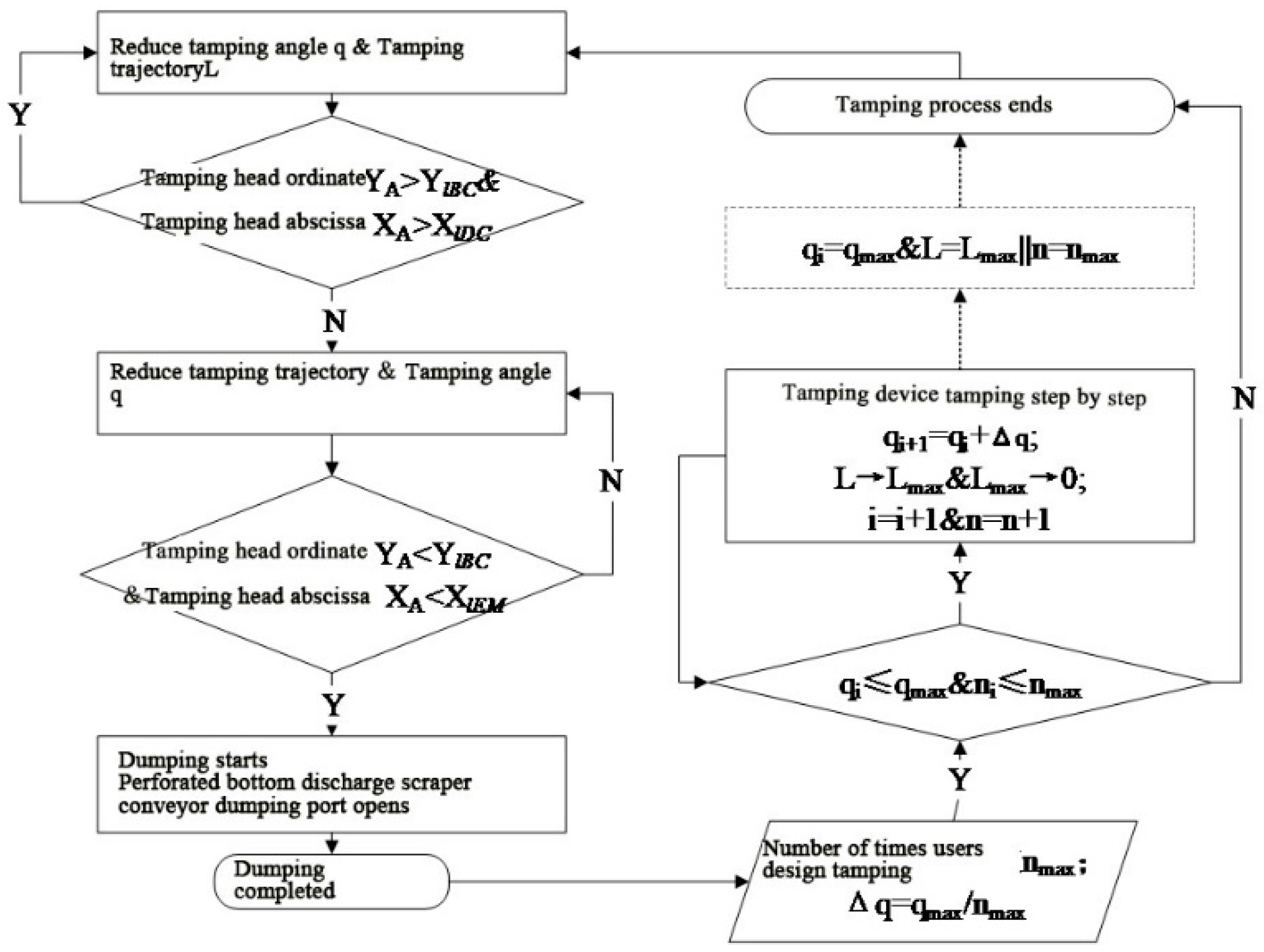
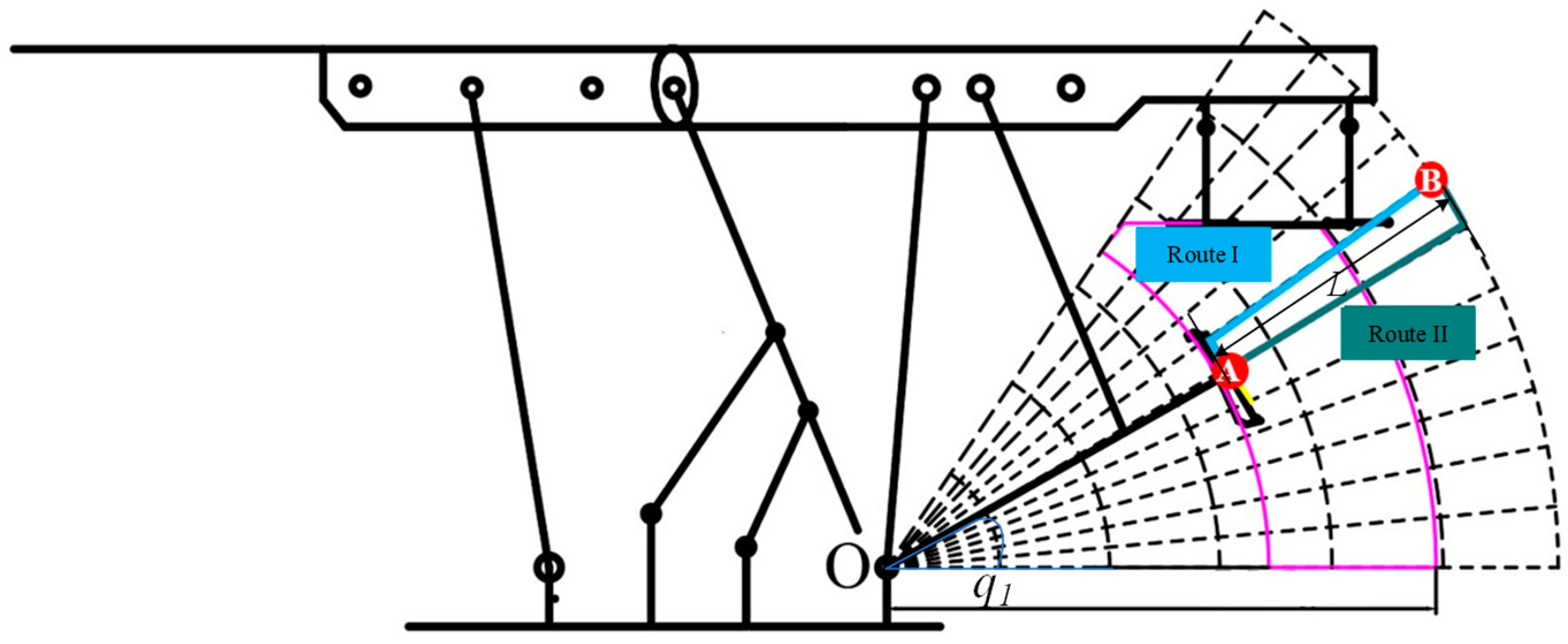
3.3. Automatic Optimization Path Planning of the Tamping Device
4. Establishment of the Simulation Test System and Design of Testing Methods
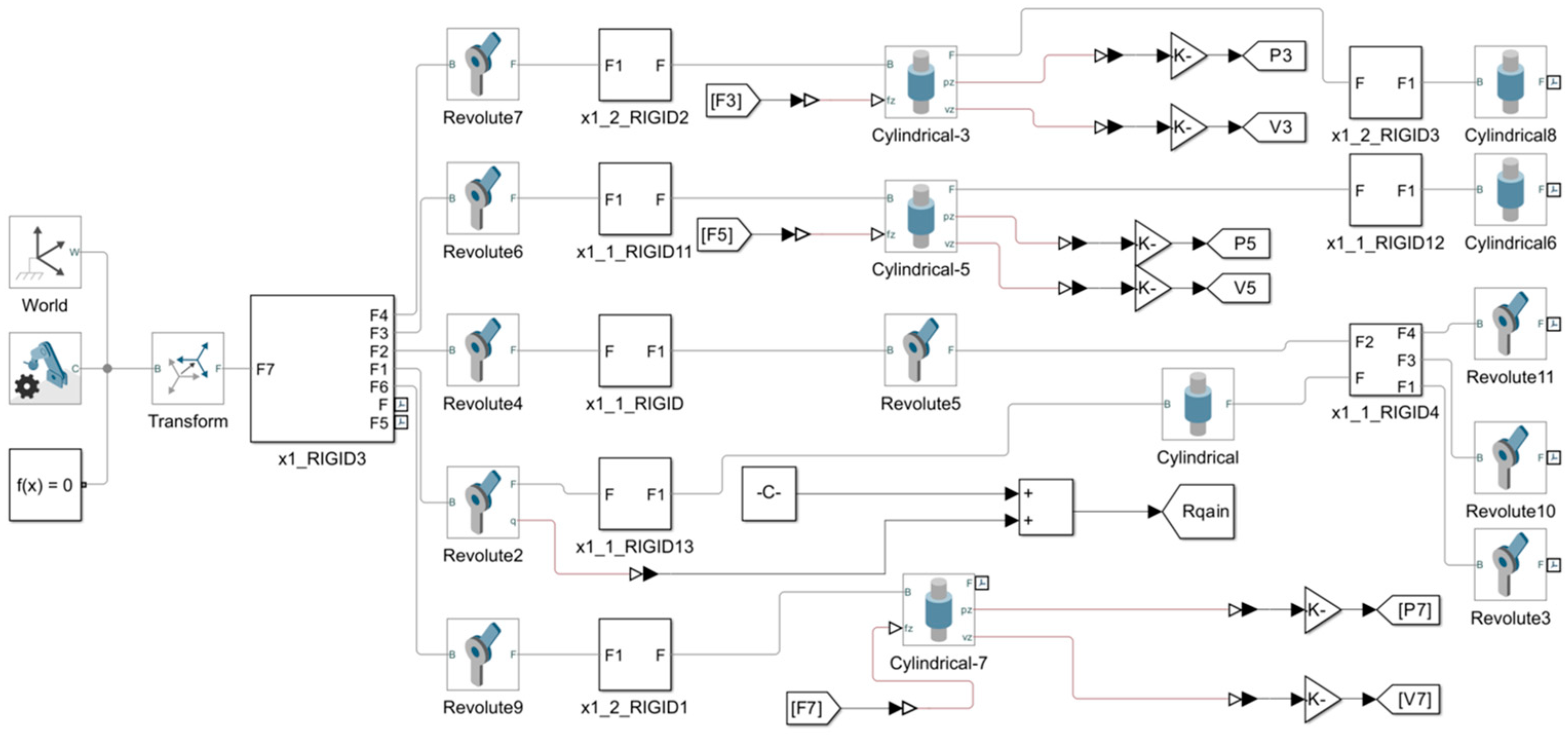
4.1. Design of the Simulation Test System Architecture
4.2. Establishment of the Simulation Test System
4.3. Design of the Simulation Testing Plan and Process Simulation
5. Engineering Cases
5.1. Overview of the Working Face and Process of the Solid Intelligent Backfilling
5.2. Model Operating-Condition Parameter Setting and Simulation Testing Scheme Design
5.3. Quantitative Analysis of the Test Results
6. Conclusions
Author Contributions
Funding
Institutional Review Board Statement
Informed Consent Statement
Data Availability Statement
Conflicts of Interest
References
- He, M.; Wang, Q.; Wu, Q. The future of mining: Thinking about the construction of intelligent 5G N00 mines. China Coal 2020, 46, 1–9. [Google Scholar]
- Wang, G.; Zhao, G.; Ren, H. Analysis on the key core technologies of smart coal mine and intelligent mining. J. Coal 2019, 44, 34–41. [Google Scholar] [CrossRef]
- Fan, J.; Li, C.; Yan, Z. The overall architecture and core scenarios of intelligent coal mines integrating 5G technology ecology. J. Coal Sci. 2020, 45, 1949–1958. [Google Scholar] [CrossRef]
- Zhang, F.; Ge, S.; Li, C. Research summary on digital twin technology for smart mines. Coal Sci. Technol. 2020, 7, 168–176. [Google Scholar] [CrossRef]
- Zhang, Q.; Zhang, J.; Wu, Z.; Chen, Y. Overview of Solid Backfilling Technology Based on Coal-Waste Underground Separation in China. Sustainability 2019, 11, 2118. [Google Scholar] [CrossRef]
- Bo, L.; Yang, S.; Liu, Y.; Zhang, Z.; Wang, Y.; Wang, Y. Coal Mine Solid Waste Backfill Process in China: Current Status and Challenges. Sustainability 2023, 15, 13489. [Google Scholar] [CrossRef]
- Hu, Y.; Li, K.; Zhang, B.; Han, B. Strength Investigation and Prediction of Superfine Tailings Cemented Paste Backfill Based on Experiments and Intelligent Methods. Materials 2023, 16, 3995. [Google Scholar] [CrossRef] [PubMed]
- Tran, V.Q. Using Artificial Intelligence Approach for Investigating and Predicting Yield Stress of Cemented Paste Backfill. Sustainability 2023, 15, 2892. [Google Scholar] [CrossRef]
- Wang, G.; Ren, H.; Zhao, G.; Du, Y. Digital model and giant system coupling technology system of smart coal mine. J. China Coal Soc. 2022, 47, 61–74. [Google Scholar] [CrossRef]
- Wang, G.; Ren, H.; Pang, Y.; Zhang, X. Research and engineering progress of coal mine intelligent (primary stage) technology system. Coal Sci. Technol. 2020, 48, 1–27. [Google Scholar]
- Wang, G.; Du, Y.; Ren, H.; Fan, J.; Wu, Q. Research and practice of top-level design of intelligent coal mines. Chin. J. Coal 2020, 45, 1909–1924. [Google Scholar] [CrossRef]
- Huang, Z. Exploration and research on transformation from intelligent single machine equipment to intelligent synergy in coal mine. Coal Sci. Technol. 2021, 49, 169–175. [Google Scholar] [CrossRef]
- Liu, Q.; Zhang, L.; Li, T.; Du, P. A three machine digital twin and collaborative modeling method for fully mechanized working face. J. Mine Au-Tomation 2023, 49, 47–55. [Google Scholar] [CrossRef]
- Wang, Y.; Shi, Y.; Wang, Y.Y.; Qi, P.L.; Wang, H.Q. Full pose measurement and virtual simulation of solid filling hydraulic support. J. Mine Autom. 2022, 48, 81–89. [Google Scholar] [CrossRef]
- Yuan, X.; Gao, F.; Lian, Z. Kinematics Simulation and Experiment Investigation of Shield Powered Support Based on MATLAB. Chin. Hydraul. Pneum. 2021, 45, 25–31. [Google Scholar] [CrossRef]
- Tian, J.; Li, Y.; Zhang, L.; Liu, Z. Adaptive control of temporary support force based on PSO-BP neural network. J. Mine Autom. 2023, 49, 67–74. [Google Scholar] [CrossRef]
- Meng, L.; Zhou, R.; Guo, Z. Design and research of hydraulic cylinder precise control test system. Coal Sci. Technol. 2023, 51, 237–245. [Google Scholar] [CrossRef]
- Zong, T.; Zhang, Q.; Shi, P. Critical characterization of solid-filled hydraulic support mechanism interference and autonomous demodulation method. Coal Sci. Technol. 2023, 51, 260–270. [Google Scholar]
- Yang, Y.; Wang, Y.; Zhang, Q.; Cheng, G. Mechanism of interference discrimination and adjustment in the mechanical independent compaction process of intelligent solid backfilling method. J. Min. Saf. Eng. 2022, 39, 921–929. [Google Scholar]
- Zhang, Q.; Wang, Y.; Zhang, J.; Zhang, Z. Research on intelligent filling mining method for coal mine solids. J. Coal 2022, 47, 2546–2556. [Google Scholar]
- Ren, H.; Li, S.S.; Li, X.; Fu, Z. Simulation analysis of the position and posture control of hydraulic support roof beam. Ind. Min. Autom. 2019, 45, 11–16. [Google Scholar]
- Zhang, Q.; Liu, Y.; Zhang, J.; Zhang, H.; Yin, W.; Wang, H. Influencing factors and control methods of mechanism interference in the autonomous compaction process of solid intelligent filling. J. Coal 2022, 47, 1043–1054. [Google Scholar] [CrossRef]
- Shi, P.; Zhang, J.; Yan, H.; Zhang, Y.; Zhang, Q. Evaluation of Operating Performance of Backfilling Hydraulic Support Using Six Hybrid Machine Learning Models. Minerals 2022, 12, 1388. [Google Scholar] [CrossRef]
- Gao, B.; Li, F. Posture Control of Hydraulic Proportional Drive Robot Arm Based on Inclination Sensor. Mach. Tool Hydraul. 2023, 51, 38–44. [Google Scholar]
- Fang, X.; Liang, M.; Li, S.; Zhang, L. Key technologies for multi-parameter accurate perception and safety decision-making in intelligent working face. J. Coal Sci. 2020, 45, 493–508. [Google Scholar] [CrossRef]
- Yang, Q.; Qu, D.; Xu, F. Path planning for mobile robots based on motion prediction of obstacles. Comput. Eng. Des. 2021, 42, 182–188. [Google Scholar] [CrossRef]
- Zhu, Y. Application of SolidWorks in hydraulic support design. Coal Min. Mach. 2013, 34, 237–239. [Google Scholar] [CrossRef]
- Huang, N.-B.; Kang, H.J. Observer-based dynamic parameter identification for wheeled mobile robots. Int. J. Precis. Eng. Manuf. 2015, 16, 1085–1093. [Google Scholar] [CrossRef]
- Han, S.; Wang, H.; Tian, Y. Model-free based adaptive nonsingular fast terminal sliding mode control with time-delay estimation for a 12 DOF multi-functional lower limb exoskeleton. Adv. Eng. Softw. 2018, 119, 38–47. [Google Scholar] [CrossRef]
- Cheng, J.; Zhu, M.; Wang, Y.H.; Yue, H.; Cui, W.X. Cascade construction of working face geological model for intelligent and precise coal mining and its key technologies. J. Coal 2019, 44, 2285–2295. [Google Scholar]


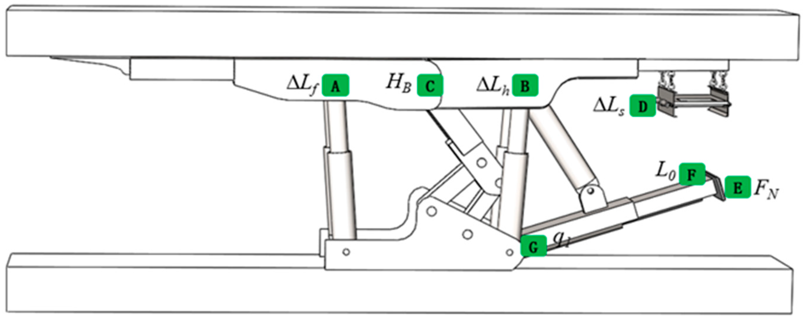
| No. | Parameter Type | Sensor Type | Installation Position |
|---|---|---|---|
| 1 | Front column path ∆Lf | Range sensor | Front-column hinge joint A |
| 2 | Rear column path ∆Lh | Range sensor | Rear-column hinge joint B |
| 3 | Front top-beam height HB | Range sensor | Front top-beam hinge joint C |
| 4 | Expansion and contraction quantities of perforated bottom discharge scraper conveyor ∆Ls | Range sensor | Scraper and jack hinge joint D |
| 5 | Tamping pressure FN | Pressure sensor | Tamping head junction E |
| 6 | Tamping path L0 | Range sensor | Tamping head junction F |
| 7 | Tamping angle q1 | Angle sensor | Tamping-device hinge joint G |
| Working Face Name | Working Face Length/m | Mining Distance/m | Mining Height/m | Average Inclination Angle/° | Recoverable Reserves/10,000 t |
|---|---|---|---|---|---|
| 1# | 58 | 633 | 4.4 | 8 | 21.6 |
| 2# | 58 | 880 | 4.6 | 12 | 31.5 |
| 3# | 58 | 730 | 4.5 | 11 | 25.5 |
| No. | Device Name | Operation Movement | Execution Device | Process Category |
|---|---|---|---|---|
| 1 | Backfilling hydraulic support | Roof guard Moving frame, lifting frame Sensing of parameters, such as support height Pose interference recognition | Cylinder guard Cylinder bottom, column Sensing element Recognition module | Support process Support process Sensing process Recognition process |
| 2 | Tamping device | Tapping angle change Sensing of parameters, such as sampling angle Pose interference demodulation | Tamping cylinder Slant-angle cylinder Sensing element Tamping cylinder, slant-angle cylinder, etc. | Tamping process Tamping process Sensing process Pose adjustment process |
| 3 | Perforated bottom discharge conveyor | Material transportation Dumping port switch Body position slip Sensing parameters, such as dumping height Pose interference demodulation | Scraper chain Dumping cylinder Slip cylinder Sensing element Dumping cylinder, Slip cylinder | Unloading process Unloading process Unloading process Sensing process Pose adjustment process |
| Design Object | Key Design Information | |||
|---|---|---|---|---|
| Assembly design | Working environment | Inclination angle/° | Mining height/mm | Device model |
| 8 | 4400 | Four-column type | ||
| Initial state | Tamping angle/° | Tamping path/mm | Column path/mm | |
| 7 | 60 | 3000 | ||
| Drive design | Drive cylinder | Front and rear columns | Slant-angle cylinder, tamping cylinder | |
| Key parameters | Front and rear column paths | Tamping angle, tamping path | ||
| Process plan | Process category | Support process | Tamping process | |
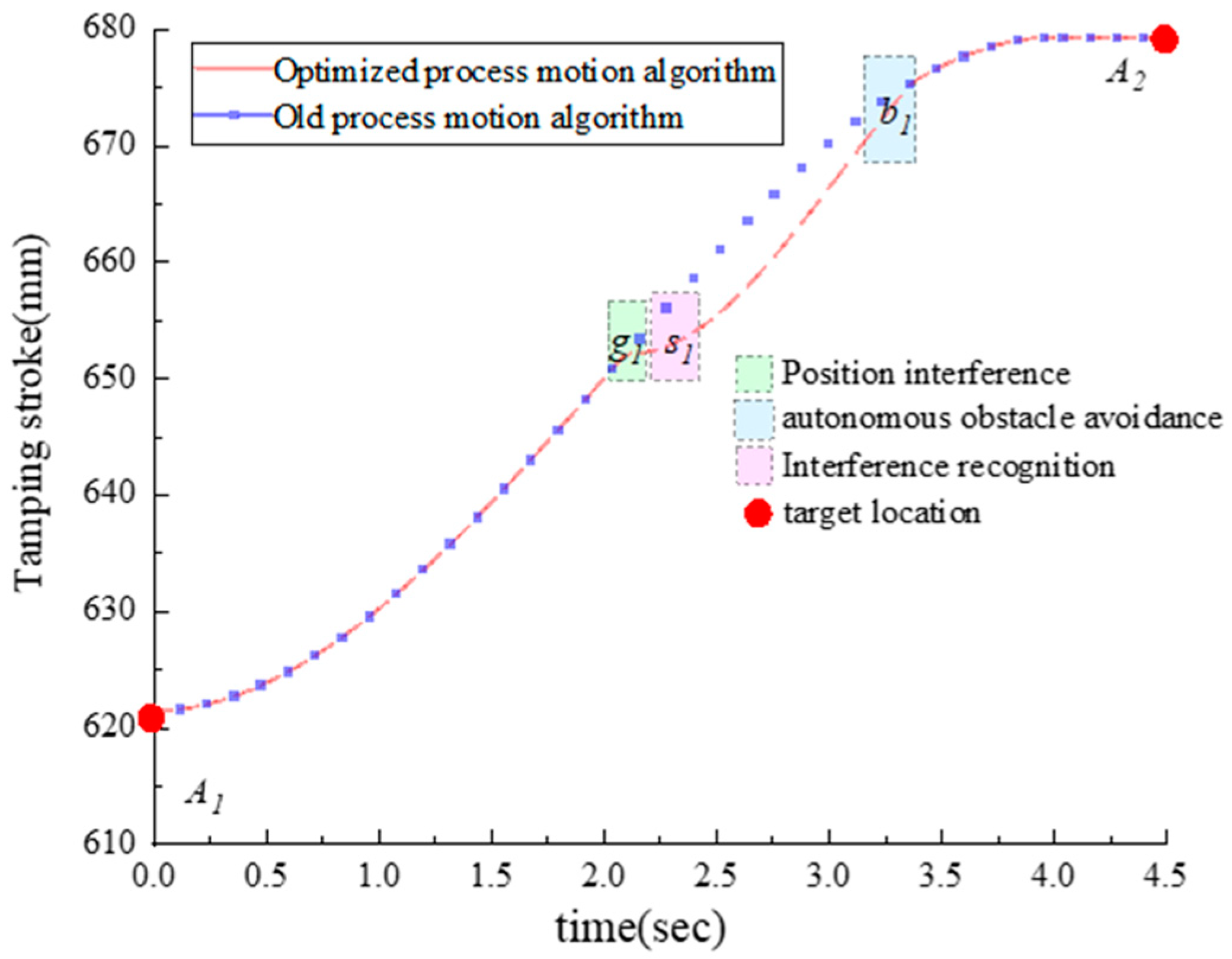
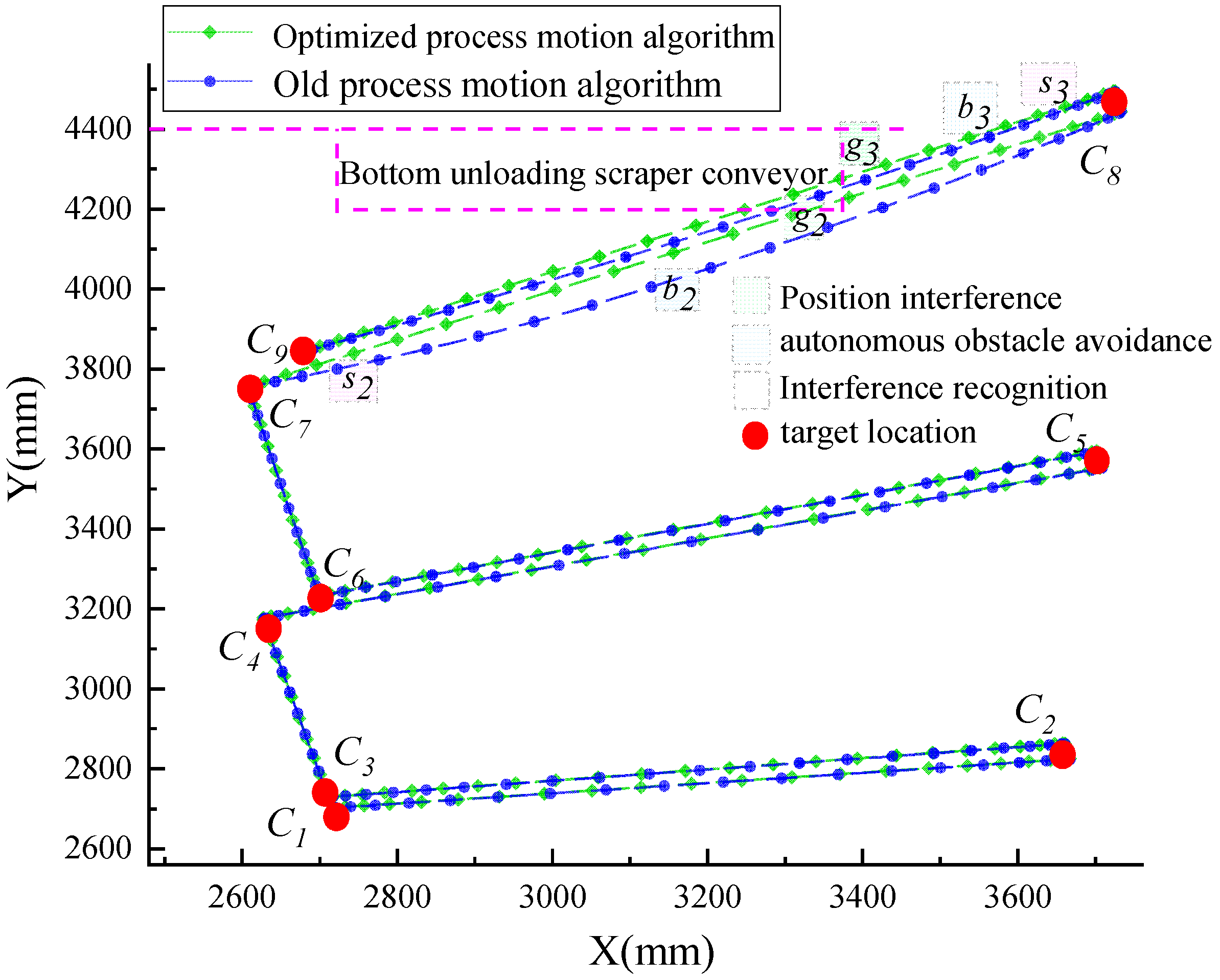
| Motion path | A1-A2 | C1-C2-C3-C4-C5-C6-C7-C8-C9 | ||
Disclaimer/Publisher’s Note: The statements, opinions and data contained in all publications are solely those of the individual author(s) and contributor(s) and not of MDPI and/or the editor(s). MDPI and/or the editor(s) disclaim responsibility for any injury to people or property resulting from any ideas, methods, instructions or products referred to in the content. |
© 2023 by the authors. Licensee MDPI, Basel, Switzerland. This article is an open access article distributed under the terms and conditions of the Creative Commons Attribution (CC BY) license (https://creativecommons.org/licenses/by/4.0/).
Share and Cite
Zong, T.; Li, F.; Zhang, Q.; Sun, Z.; Lv, H. Autonomous Process Execution Control Algorithms of Solid Intelligent Backfilling Technology: Development and Numerical Testing. Appl. Sci. 2023, 13, 11704. https://doi.org/10.3390/app132111704
Zong T, Li F, Zhang Q, Sun Z, Lv H. Autonomous Process Execution Control Algorithms of Solid Intelligent Backfilling Technology: Development and Numerical Testing. Applied Sciences. 2023; 13(21):11704. https://doi.org/10.3390/app132111704
Chicago/Turabian StyleZong, Tingcheng, Fengming Li, Qiang Zhang, Zhongliang Sun, and Haonan Lv. 2023. "Autonomous Process Execution Control Algorithms of Solid Intelligent Backfilling Technology: Development and Numerical Testing" Applied Sciences 13, no. 21: 11704. https://doi.org/10.3390/app132111704
APA StyleZong, T., Li, F., Zhang, Q., Sun, Z., & Lv, H. (2023). Autonomous Process Execution Control Algorithms of Solid Intelligent Backfilling Technology: Development and Numerical Testing. Applied Sciences, 13(21), 11704. https://doi.org/10.3390/app132111704