Wedge Design and Dynamic Characteristics Analysis of Unequal-Length Wedge Slant Support Clutch

Abstract
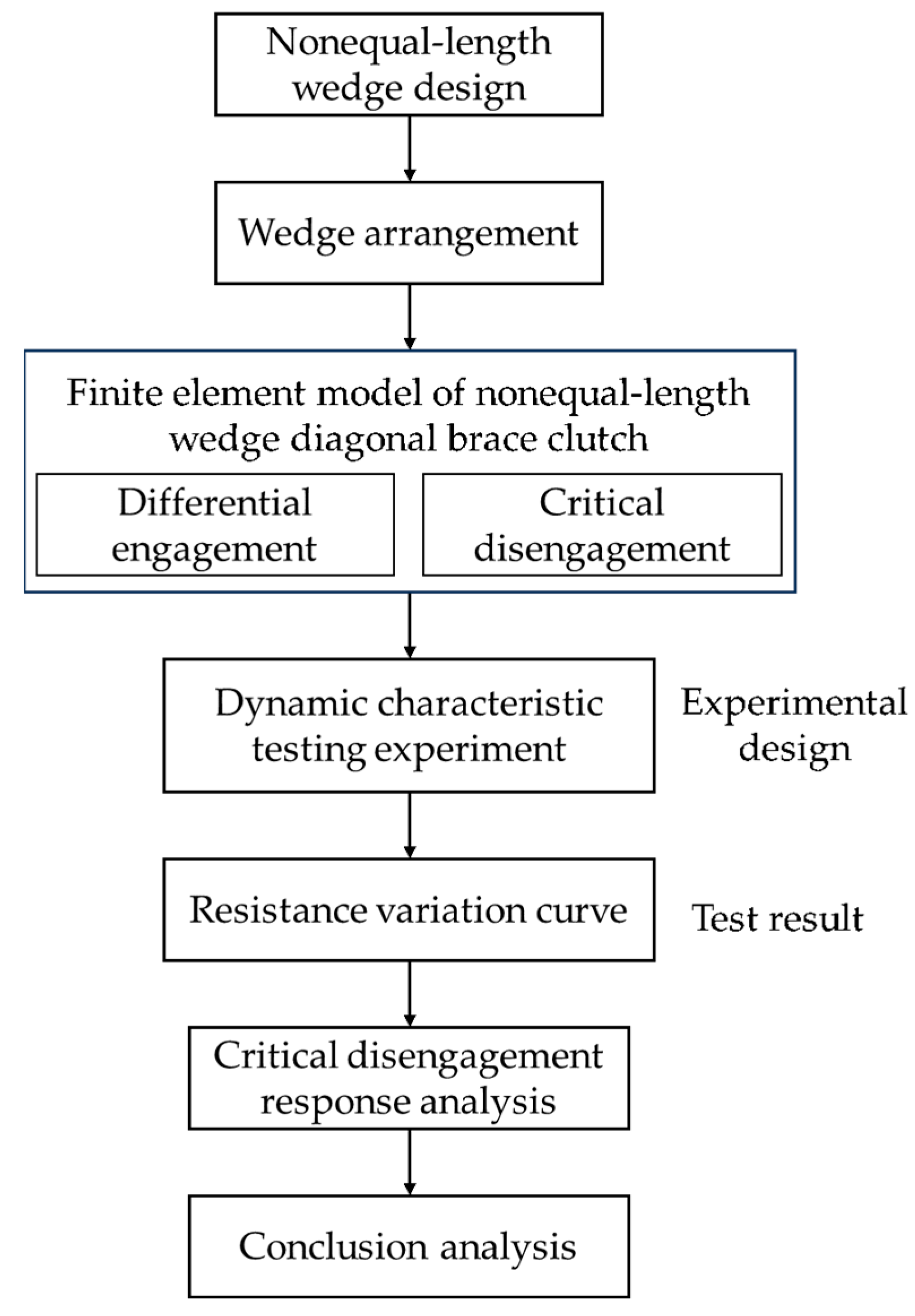
:1. Introduction
2. Unequal-Length Wedge Diagonal Brace Clutch Design
2.1. Working Principle of Unequal-Length Wedge Diagonal Brace Clutch
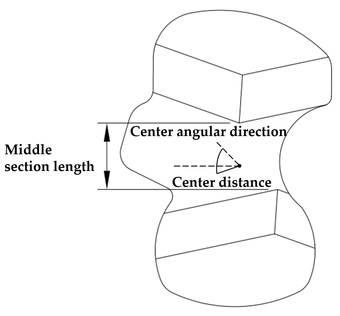
2.2. Unequal-Length Wedge Design
2.2.1. Wedge Difference Quantity
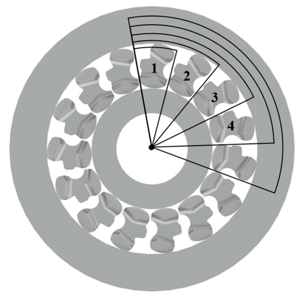
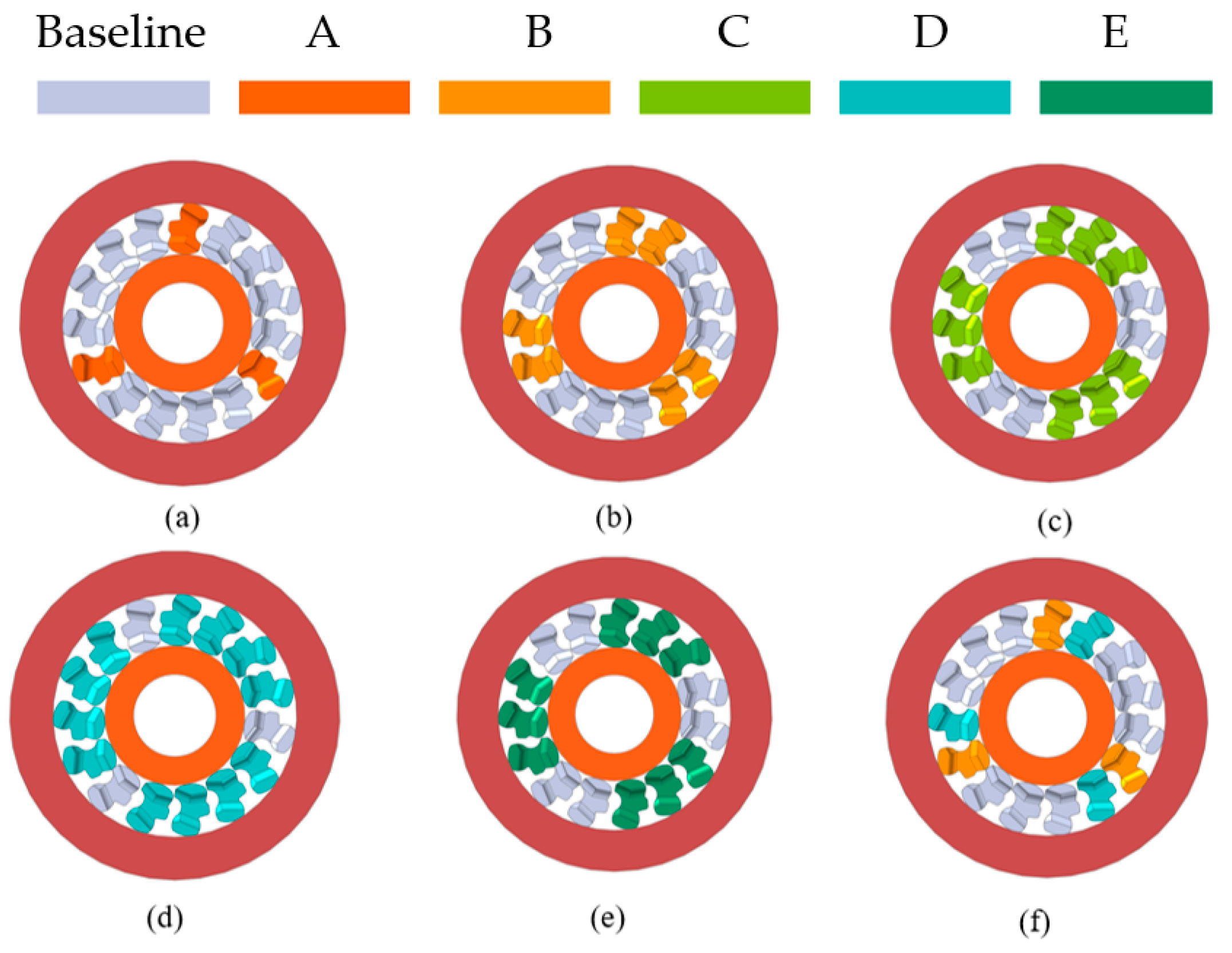
2.2.2. Wedge Distribution
2.2.3. Number of Wedges
2.2.4. Verification of Design Parameters
3. Analysis of Dynamic Characteristics of Differential Engagement of Slant Support Clutch
3.1. Establishment of Dynamic Model for Clutch Differential Engagement
3.2. Analysis of Simulation Results
3.2.1. Conventional Slant Support Clutch
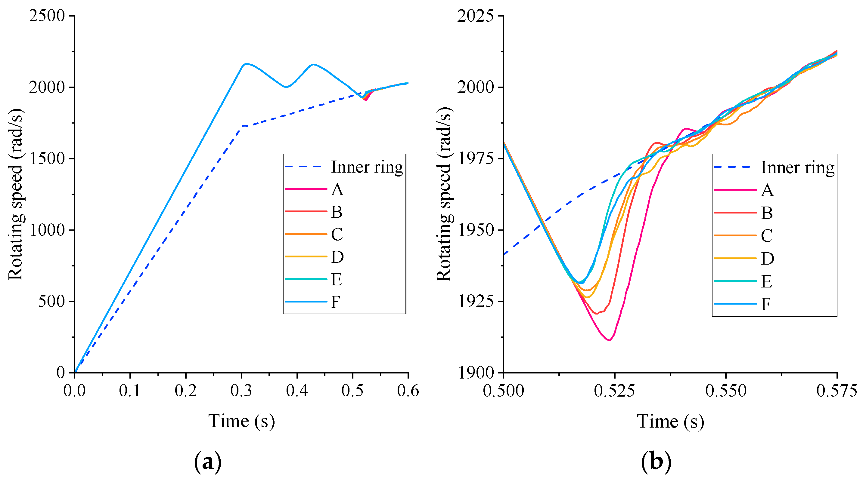
- Approximately 0.1 s after the speed of the clutch outer ring is withdrawn, the speed of the inner and outer rings remains the same. During this period, the speed decrease rate of the outer ring of the clutch remains constant until 0.526 s. At this point, the wedge is completely detached from the inner ring until the speed of the outer ring decreases to approximately 1900 rad/s and the bonding conditions are re-established.
- The phenomenon of PCE on the wedge block is speculated to be caused by the excessive deformation between the inner and outer rings of the clutch and wedge block.
- Owing to the excessive impact, the wedge deflects further, which is similar to the phenomenon of overload deflection in an all-phase clutch. There is always a certain difference between the speed of the outer ring and that of the inner ring of the clutch, and the torque transmission performance of the slanted support clutch declines significantly.
- During the simulation process, there was an overload deflection phenomenon, and under actual working conditions, the clutch could have been in a failed or damaged state and, thus, unable to meet the usage requirements.
3.2.2. Two Sets of Unequal-Length Wedge Slant Support Clutch
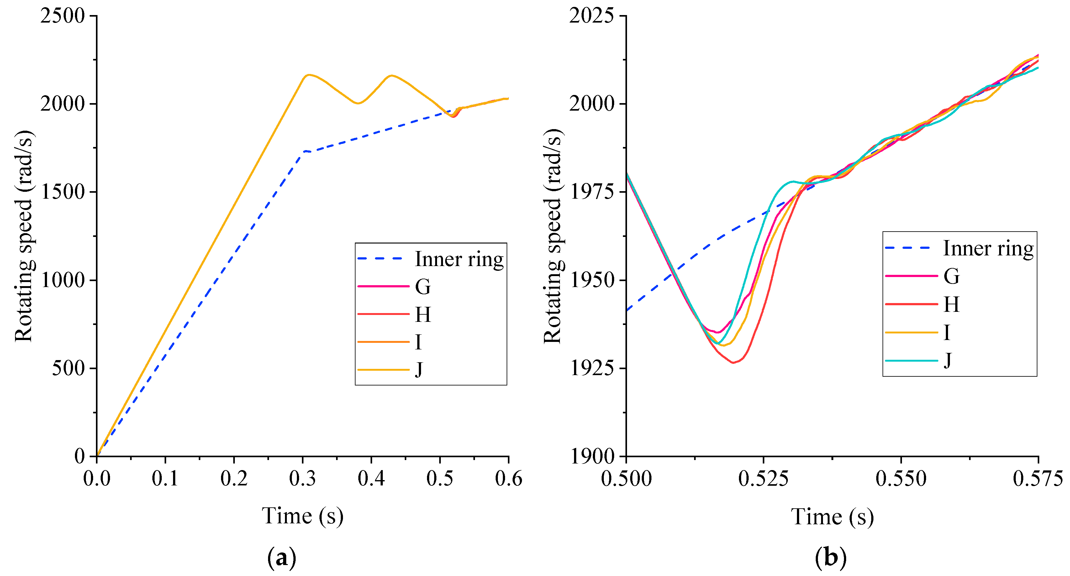
3.2.3. Three Sets of Unequal-Length Wedge Slant Support Clutch
4. Dynamic Characteristics Analysis of Critical Disengagement of Slant Support Clutch
4.1. Critical Disengagement State of Clutch
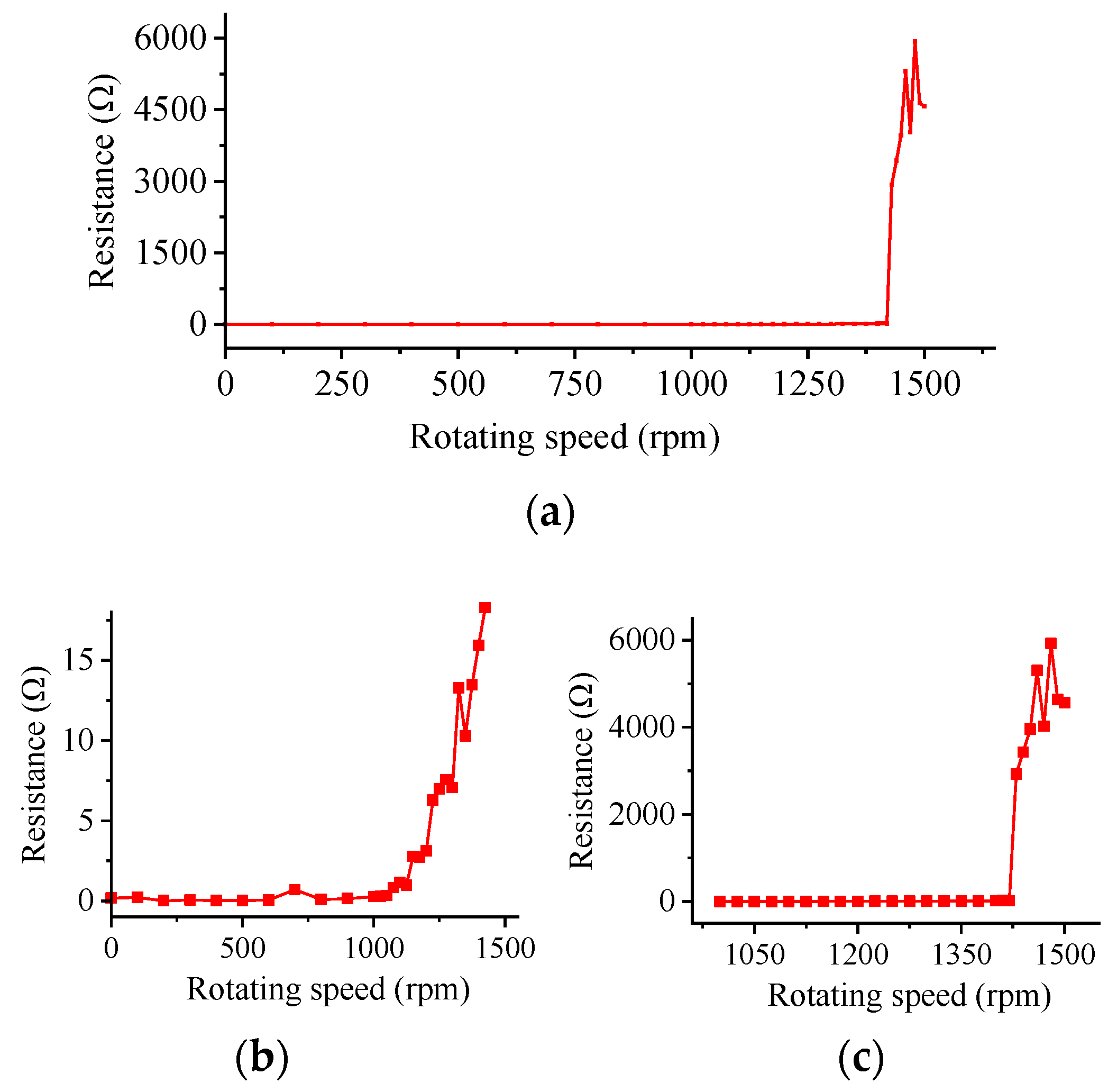
4.2. Simulation Analysis of Critical Disengaging Speed
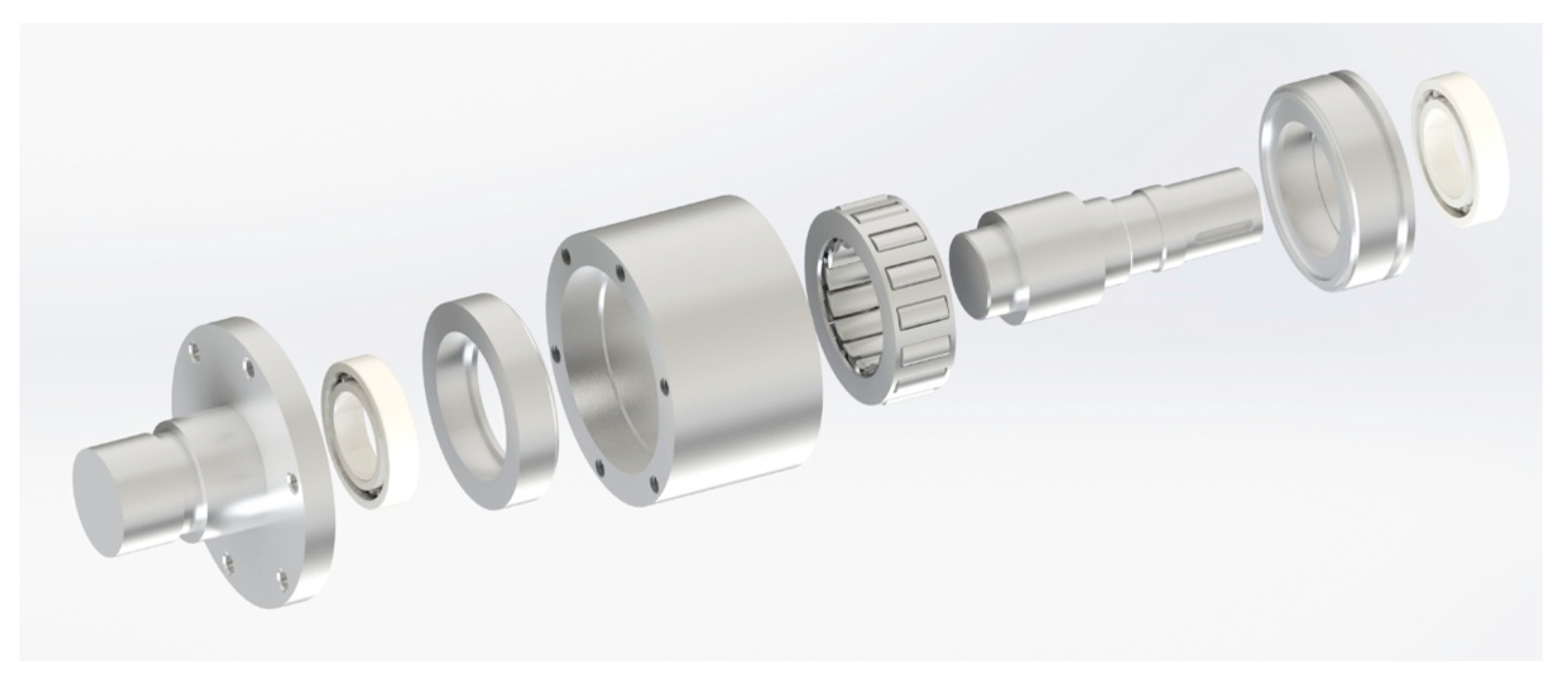
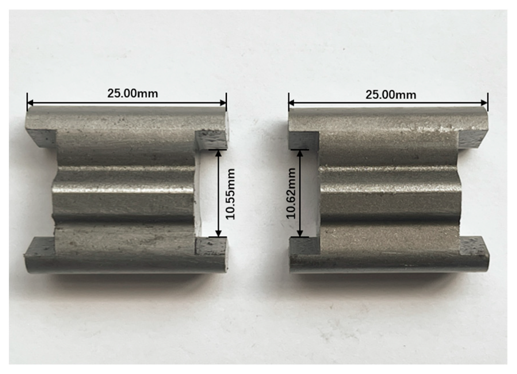
5. Dynamic Characteristic Testing Experiment
6. Conclusions
- The design parameters of unequal-length wedge were provided, and the wedge angle constraint, lift constraint, PCE constraint, and other conditions were verified. A series of “slow contact” clutch design schemes were determined, and the engagement performance of the unequal-length wedge slant support clutch was verified through experiments.
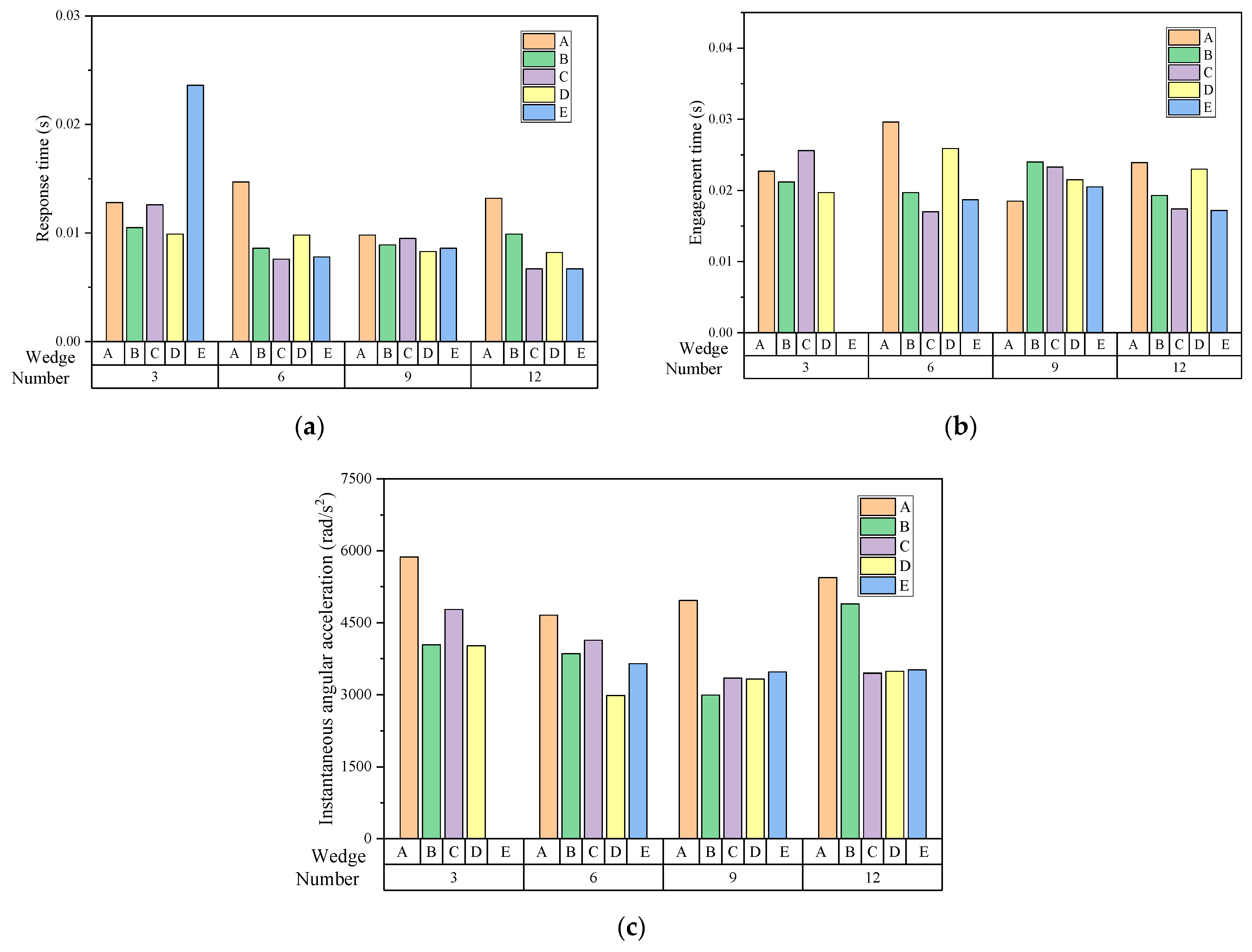
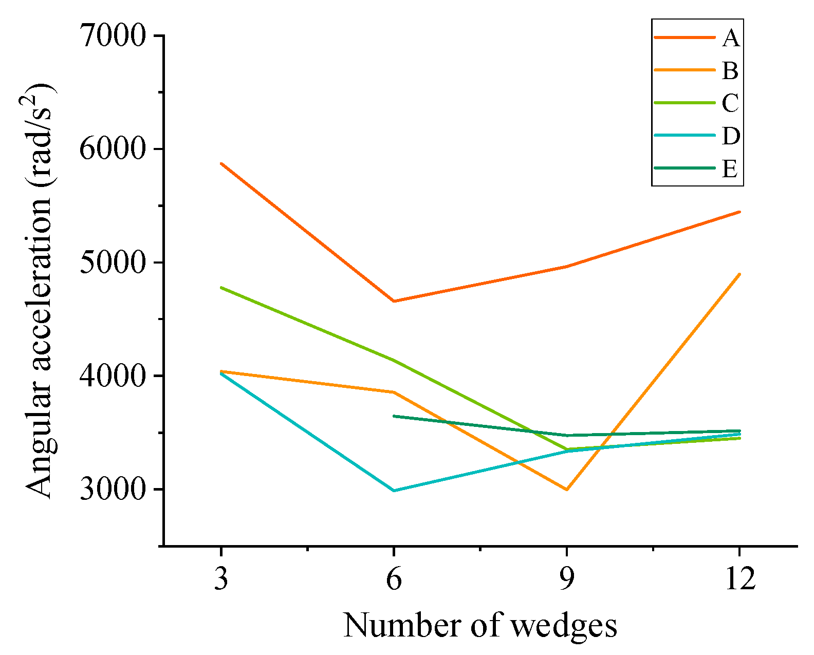
- Under the condition of using the same type of wedge, the instantaneous angular acceleration of the outer ring of the “slow connect”-type clutch demonstrated a significant trend of first decreasing and then increasing with the increase in the number of long wedges. The response and engagement times of the clutch demonstrated a decreasing trend with an increase in the number of long wedges. Under the same number of wedges, the instantaneous angular acceleration, clutch response time, and engagement time of the outer ring of the clutch decreased with an increase in the wedge difference.
- There is a direct proportional relationship between the wedge difference and critical detachment speed. For every 0.005 mm increase in wedge difference, the critical detachment speed of the wedge increased by approximately 2%. The effectiveness of the critical detachment mathematical model was demonstrated through experimental verification.
Author Contributions
Funding
Data Availability Statement
Conflicts of Interest
References
- Xue, H.; Liu, G.; Yang, X.; Han, B. Key technologies research of helicopter transmissions. AMM 2015, 743, 55–60. [Google Scholar] [CrossRef]
- Kish, J. Helicopter Freewheel Unit Design Guide; [Department of Defense, Department of the Army], Army Research and Technology Laboratories, Applied Technology Laboratory: Adelphi, MD, USA, 1977.
- Chen, L.W.; Chen, Y.C. Wedge-shaped track design and contact analysis of overrunning clutches. Proc. Inst. Mech. Eng. Part D J. Automob. Eng. 2008, 222, 1647–1656. [Google Scholar] [CrossRef]
- Xu, T.; Lowen, G.G. A New Damping Model for Nonlinear Stiffness Systems With Variable Preload Displacements and Constant Amplitude Decay Ratios. In Proceedings of the International Design Engineering Technical Conferences and Computers and Information in Engineering Conference, Scottsdale, AZ, USA, 13–16 September 1992; American Society of Mechanical Engineers: New York, NY, USA, 1992; Volume 9402. [Google Scholar]
- Huang, C.; Liu, M.; Zhao, Y. An Analytical Model of Multiarc Sprag Clutch considering Geometry and Internal Interaction during Engagement. Shock Vib. 2017, 2017, 2393578. [Google Scholar] [CrossRef]
- Huang, C.; Zhao, Y.; Liu, M.; Fu, Z. Dynamic modelling and vibration analysis of dual-rotor system with inter-shaft sprag clutch and bearings. In Proceedings of the 2019 22nd International Conference on Electrical Machines and Systems (ICEMS), Harbin, China, 11–14 August 2019. [Google Scholar]
- Huang, C. Wedging Optimization and Vibration Characteristics of Slant Support Clutch Rotor System. Ph.D. Thesis, Harbin Institute of Technology, Harbin, China, 2020. [Google Scholar]
- Qing, M.; Yan, H.; Tan, W. Research on the Failure Judgment of Sprag Clutch Based on Wear Loss. AMM 2013, 378, 329–334. [Google Scholar] [CrossRef]
- Qing, M.; Yan, H.; Tan, W. The Effects of the Manufacturing Errors of a Group of Sprags on the Engagement Properties of Sprag Clutch. Adv. Mater. Res. 2013, 744, 18–22. [Google Scholar] [CrossRef]
- Liu, Z.; Yan, H.; Cao, Y. Design and analysis of logarithmic spiral type sprag one-way clutch. J. Cent. South Univ. 2015, 22, 4597–4607. [Google Scholar] [CrossRef]
- Liu, Z.; Yan, H.; Cao, Y.; Lai, Y. Bifurcation and Chaos Analysis of the Spur Gear Transmission System for One-Way Clutch, Two-Shaft Assembly. Shock Vib. 2017, 2017, 8621514. [Google Scholar] [CrossRef]
- Yan, H.; Wang, Z.; Zhu, C. The influence of the position of the wedge center of gravity on the performance of the slant support clutch. Chin. J. Mech. Eng. 2021, 32, 253. [Google Scholar]
- Yan, H.; Wen, B.; Wang, Z. Wear Analysis of Support Spring of Sprag Clutch during State of Overrunning. Math. Probl. Eng. 2022, 2022, 3417760. [Google Scholar] [CrossRef]
- Huang, C.; Zhao, Y.; Liu, M. Analytical modeling and optimization of logarithmic sprag clutch considering profile modification. Shock Vib. 2018, 2018, 4190303. [Google Scholar] [CrossRef]
- Han, T.; Bai, Z.; Quan, J. Failure analysis of overrunning clutch for turbine starter. Bearing 2023, 7, 56–61. [Google Scholar]
- Ma, L.; Meng, H.; Han, H. Research on the Wear and Failure of Cylindrical Rollers in Alien Wheel Overrunning Clutch. Met. Process. (Cold Work.) 2020, 1, 84–86. [Google Scholar]
- Xue, Y.; Wang, Z.; Chen, D.; Tao, S.; Lu, Y. Design and Test of a New Type of Overrunning Clutch. Machines 2022, 10, 1188. [Google Scholar] [CrossRef]
- Liu, H.; Ning, F. High speed overrunning slant support clutch differential engagement impact load estimation. Mech. Transm. 2011, 35, 21–22. [Google Scholar]
- Zhu, Z. Research on Design Technology of High Speed Overrunning Slant Support Clutch. Master’s Thesis, Nanjing University of Aeronautics and Astronautics, Nanjing, China, 2004. [Google Scholar]
- ISO 24195:2022(EN); Road Vehicles—Vocabulary and Characteristics for Engineering of Starting Devices. ISO: Geneva, Switzerland, 2022.
- China Aerospace Shenyang Engine Research Institute. A Method for Determining the Release Speed of Ratchet Clutch. China Patent No. CN202011628428.2, 19 October 2021.


| Item | Wedge A | Wedge B | Wedge C | Wedge D | Wedge E |
|---|---|---|---|---|---|
| Wedge difference quantity (mm) | +0.005 | +0.010 | +0.015 | +0.020 | +0.025 |
| Length of middle segment (mm) | 1.3550 | 1.3600 | 1.3650 | 1.3700 | 1.3750 |
| Center distance (mm) | 0.3233 | 0.3228 | 0.3224 | 0.3221 | 0.3218 |
| Center corner (°) | 6.50 | 5.62 | 4.74 | 3.85 | 2.96 |
| Model | B | D | ||
|---|---|---|---|---|
| Number of Wedges | Location | Number of Wedges | Location | |
| 1 | 3 | 1 | 3 | 2 |
| 2 | 6 | 1, 2 | 3 | 3 |
| 3 | 3 | 1 | 6 | 2, 3 |
| 4 | 6 | 1, 3 | 6 | 2, 4 |
| Parameter | Baseline | Wedge A | Wedge B | Wedge C | Wedge D | Wedge E |
|---|---|---|---|---|---|---|
| Internal wedge angle V (°) | 3.6308 | 3.6241 | 3.6184 | 3.6139 | 3.6106 | 3.6071 |
| External wedge angle W (°) | 2.0745 | 2.0707 | 2.0674 | 2.0648 | 2.0629 | 2.0610 |
| External normal contact force Fo (N) | 5908.69 | 5919.74 | 5928.98 | 5936.39 | 5941.96 | 5947.55 |
| Internal normal contact force Fi (N) | 5900.70 | 5911.76 | 5921.02 | 5928.44 | 5934.02 | 5939.61 |
| Wedge | Response Time (s) | Engagement Time (s) | Instantaneous Angular Acceleration (rad/s2) |
|---|---|---|---|
| Baseline | 0.0188 | 0.0386 | 7673.64 |
| A | 0.0126 | 0.0237 | 5233.96 |
| B | 0.0095 | 0.0211 | 3947.51 |
| C | 0.0091 | 0.0208 | 3929.67 |
| D | 0.0091 | 0.0225 | 3457.31 |
| E | 0.0084 | 0.0194 | 3545.20 |
| Mode | Number of Wedges | Response Time (s) | Engagement Time (s) | Instantaneous Angular Acceleration (rad/s2) | |
|---|---|---|---|---|---|
| B | D | ||||
| G | 3 | 3 | 0.0105 | 0.0212 | 4691.38 |
| H | 6 | 3 | 0.0105 | 0.0230 | 3897.46 |
| I | 3 | 6 | 0.0075 | 0.0200 | 3009.08 |
| J | 6 | 6 | 0.0087 | 0.0219 | 3231.20 |
| mean value | 0.0093 | 0.0215 | 3707.28 | ||
| Wedge | Critical Disengagement Speed (rpm) | Change Rate (%) | |
|---|---|---|---|
| Min | Max | ||
| Baseline | 12,111.55 | 12,801.28 | 0% |
| A | 12,287.73 | 12,996.79 | 1.53% |
| B | 12,377.38 | 13,096.44 | 2.32% |
| C | 12,455.76 | 13,183.66 | 3.00% |
| D | 12,635.14 | 13,383.56 | 4.57% |
| E | 12,764.48 | 13,528.00 | 5.70% |
| Wedge | Critical Disengagement Speed (rpm) | Change Rate (%) |
|---|---|---|
| Baseline | 11,676.82 | 0% |
| A | 12,056.42 | 3.30% |
| B | 12,280.78 | 5.20% |
| C | 12,408.36 | 6.20% |
| D | 12,775.58 | 9.40% |
| E | 13,059.49 | 11.80% |
| Wedge | Critical Disengagement Speed (rpm) | Relative Error | |
|---|---|---|---|
| Theoretical Scope | Test Value | ||
| Baseline | [1268.32, 1340.54] | 1325 | 1.12% |
| E | [1224.68, 1360.94] | 1430 | 5.14% |
Disclaimer/Publisher’s Note: The statements, opinions and data contained in all publications are solely those of the individual author(s) and contributor(s) and not of MDPI and/or the editor(s). MDPI and/or the editor(s) disclaim responsibility for any injury to people or property resulting from any ideas, methods, instructions or products referred to in the content. |
© 2023 by the authors. Licensee MDPI, Basel, Switzerland. This article is an open access article distributed under the terms and conditions of the Creative Commons Attribution (CC BY) license (https://creativecommons.org/licenses/by/4.0/).
Share and Cite
Zhu, C.; Wu, J.; Wu, X.; Lei, M.; Yan, H. Wedge Design and Dynamic Characteristics Analysis of Unequal-Length Wedge Slant Support Clutch. Appl. Sci. 2023, 13, 11718. https://doi.org/10.3390/app132111718
Zhu C, Wu J, Wu X, Lei M, Yan H. Wedge Design and Dynamic Characteristics Analysis of Unequal-Length Wedge Slant Support Clutch. Applied Sciences. 2023; 13(21):11718. https://doi.org/10.3390/app132111718
Chicago/Turabian StyleZhu, Chu, Jiangming Wu, Xueshen Wu, Mingtao Lei, and Hongzhi Yan. 2023. "Wedge Design and Dynamic Characteristics Analysis of Unequal-Length Wedge Slant Support Clutch" Applied Sciences 13, no. 21: 11718. https://doi.org/10.3390/app132111718