Article

Speed Reduction Capabilities of Two-Geometry Roundabouts

Faculty of Civil Engineering, University of Zagreb, 10000 Zagreb, Croatia
*
Author to whom correspondence should be addressed.
Appl. Sci. 2023, 13(21), 11816; https://doi.org/10.3390/app132111816
Submission received: 29 September 2023 / Revised: 25 October 2023 / Accepted: 27 October 2023 / Published: 29 October 2023

Abstract

:
Several types of modern roundabouts are alternatives to standard ones. They are either in use or at the development stage today. One such intersection is the two-geometry roundabout. Its circulatory roadway has an elliptical outer edge and a circular inner edge that is defined by a circular central island resulting in variable circulatory roadway width. The investigation presented in this paper aims to determine the influence of this variable width on the design of other geometric elements and its impact on roundabouts’ speed reduction capabilities. There is not enough experimental data collected to make a comparison to other roundabout types, so this investigation is based on computer simulations and speed estimations. The investigation is conducted on 40 four-legged single-lane roundabout schemes. These were designed in the Autodesk AutoCAD 2021 software through computer simulations of vehicle movement and the resulting swept paths of a tractor with a semi-trailer generated by the Autodesk Vehicle Tracking 2020 software. The results show that truck aprons must be included in the design of two-geometry roundabouts with a major axis between 18 and 25 m to achieve appropriate circulatory roadway widths, personal car path deflection, and the resulting relative speed and speed consistency.

1. Introduction

Modern roundabouts are intersections with a raised central island and a circulatory roadway at which the yield-at-entry rule is applied. At these types of intersections, the traffic is continuous and circulates at low speed in one direction on a circulatory roadway toward the exits at the intersection legs [1]. When adequately designed, modern roundabouts provide numerous benefits compared to conventional intersections, such as improved intersection safety and capacity, better vehicle speed management, reduced maintenance costs, and reduced pollution generated by road traffic [2,3,4,5,6,7].
The benefits of modern roundabouts result from the fact that they are designed to control traffic speeds [8,9]. This control is achieved through the selection of appropriate design elements that result in adequate vehicle path curvature upon entry, around the central island, and upon exit. It is considered that the driving speed through the roundabout is mostly influenced by the deflection of the vehicle path, which is caused by the roundabout’s central island. The influence of deflection on roundabout performance is evaluated either by measuring the deflection provided by roundabouts’ design elements (for example, using the procedure given in [10]) or by defining the radius (or radii) of the centerline of a vehicle traveling along the so-called fastest path through the roundabout and then calculating the vehicle speed [11]. This theoretical fastest path is representative of the most used trajectory by drivers under free flow conditions when minimizing their driving discomfort [12]. In the latter approach, speed prediction models that are based on fundamental functions of vehicle dynamics are used. For example, the FHWA model, described in [13], predicts the speed for five locations on the fastest paths (right-turn, left-turn, through circulating, exit, or entry movements) based on the vehicle path radii, side friction factor, and superelevation on these locations. On the other hand, the CROW model, described in [14], gives a single value of vehicle speed for all specific locations on the through path: the entry, around the central island, and the exit. It predicts the expected driving speed through the roundabout based on the vehicle path radius. This radius is calculated using measured roundabout design elements and it is assumed to be constant along the vehicle through path. There are also empirically derived speed prediction models, such as a multiple linear regression model developed for Italian roundabouts (described in [15]) or a model for speed prediction that includes the central island diameter and the average of entry, circulating, and exit widths as derived variables (described in [8]). The investigations that led to the development of these models showed that the FHWA model overestimates entry and exit speed values. At the same time, investigation results given in [16] showed that the CROW model results in an even larger estimated speed compared to the FHWA model and that these differences are proportional to the path radius.
As described in detail in [1], roundabout design, i.e., the selection of roundabouts’ design elements, is an iterative process that is comprised of the following steps. The first step is the selection of the roundabout size, considering the spatial limitations and the number and alignment of the legs. The second step is the selection of the circulatory roadway width. The third step is the selection of the splitter island shape, which is conditioned by the required level of traffic flow channeling, as well as the design of the right carriageway edge. The fourth step is the control of the selected geometry, i.e., the swept path analysis for a design vehicle (a vehicle identified as the least maneuverable vehicle expected to use the intersection), the fastest path analysis for personal cars, and visibility checks. When design elements meet the conditions of these performance checks, a detailed roundabout design is conducted. This iterative process can be simplified by designing the circulatory roadway and the right carriageway edge according to the results of the design vehicles’ swept path analyses. These analyses are conducted with software for vehicle movement simulation today. This approach is an effective way to determine the optimal roundabout design elements because it incorporates the optimization technique rather than a trial-and-error process [17,18,19].
Today, several types of modern roundabouts represent an alternative to standard single-lane or double-lane roundabouts. They differ in one or more design elements, have different impacts on traffic safety, capacity, mobility, and the environment, and are either in usage worldwide (for example, hamburger, turbo, and peanut roundabouts) or still in the development phase (for example, flower, target, and elliptical roundabouts and roundabouts with segregated left-turn slip-lanes) [20,21,22]. One such alternative modern roundabout is the so-called two-geometry roundabout. This roundabout has variable circulatory roadway width due to the different roadway edge shapes: the outer edge is elliptical, and the inner edge, which is defined by the shape of a central island, remains circular [22]. This peculiarity differentiates them from elliptical roundabouts, i.e., roundabouts with elliptical outer and inner edges. Its circular central island should provide increased deflection of personal vehicle paths which results in lower vehicle speed [22].
As the number of constructed two-geometry roundabouts is still low, there is not yet enough experimental data collected to make a robust comparison to other modern roundabout types [22]. Therefore, computer simulations must be conducted to determine the optimum geometry of these intersections and their overall applicability in the road network. The main gap to be filled is the influence of the variable circulatory roadway width (which can be significantly wider compared to the standard single-lane roundabouts [22]) on the design of other geometric elements. Additionally, their impact on traffic safety, i.e., the vehicle path deflection around the central island these roundabouts provide, and, consequently, their capability for personal vehicles’ speed reduction and consistency should be investigated.
In this paper, 40 four-legged single-lane roundabout schemes were designed in the Autodesk AutoCAD 2021 software utilizing computer simulations of vehicle movement and the resulting swept paths generated by the Autodesk Vehicle Tracking 2021 software. The reliability of this software is discussed in the paper [23], where the simulated swept path widths are compared with the ones determined using a precise GNSS device at a test site. The results of this investigation showed that from a statistical point of view, these swept path widths did not differ, so the software can be used for further investigation. The design vehicle selected for the investigation presented in this paper was a tractor with a semi-trailer. This long, articulated vehicle was selected because these types of vehicles face issues while maneuvering the roundabout due to their large turning envelope requirements [19,24]. The investigation included the determination of the vehicle path deflection provided by the designed central island and the determination of passenger vehicle speed through the designed roundabout schemes based on the following approaches: (1) by measuring the deflection provided by the designed roundabout’s geometrical features; (2) by measuring the designed roundabout’s geometrical features and calculating the fastest path radii and vehicle speed using the CROW model; (3) by constructing the fastest through paths, measuring the path radii upon entry, around the central island, and upon exit (according to the FHWA model) and then calculating the vehicle speed for each location using the CROW model. The aim was to determine whether the designed two-geometry roundabout elements provide the appropriate vehicle speed reduction. Additionally, the consistency between consecutive geometric elements on personal vehicle fastest paths was investigated. The results showed that two-geometry roundabouts can easily be designed by utilizing computer simulations of design vehicle movement and the resulting swept paths. At the same time, the initially analyzed roundabout schemes did not provide sufficient safety. Namely, the resulting circulatory roadway widths were significantly larger than the recommended values and the achieved deflection did not provide the required speed reduction. Therefore, it was concluded that truck aprons must be included in the design of two-geometry roundabouts to achieve sufficient personal vehicle speed reduction and consistency.
The paper is organized as follows. Input parameters and methods used in the investigation are presented in Section 2. The results of the investigation are given in Section 3. These results are discussed and interpreted from the perspective of the investigated roundabout design elements’ applicability and safety in Section 4. In the same section possible future research directions are highlighted. Conclusions are drawn in Section 5.

2. Experiment Design and Methodology

The investigation presented in this paper was conducted on 40 single-lane roundabout schemes designed in the Autodesk AutoCAD 2021 software. A total of 32 initial schemes (Figure 1a) were constructed by varying the major axis of the elliptical outer edge of a two-geometry roundabout (a) from 18 to 25 m, with a 1 m increment. According to previous research given in [19], these outer radii are commonly used for single-lane roundabouts worldwide. An increment of 1 m was chosen to capture the dispersity of the results and to create a sample that is representative, manageable, and easy to present at the same time.
According to [22], the minor axis of the elliptical outer edge of a two-geometry roundabout (b) is determined using the following equation:
0.75 < b/a < 0.90.
In this investigation, for each major axis (a), four two-way geometry roundabouts were designed by varying the minor axis of the elliptical outer edge of a two-geometry roundabout (b), as shown in Table 1. Eight initial schemes were created to represent a standard modern roundabout with an outer radius (R = a) between 18 and 25 m, designed with a 1 m increment. Roundabout approach leg axes in all schemes intersect in the center of the roundabout’s outer edge, as shown in Figure 1a. Approach legs are radial to the outer edge, and their axes intersect in the center of the roundabout. A triangular splitter island, 15 m long, 3 m wide, and placed 0.5 m from the roundabout outer edge, was selected for this investigation.
Carriageway widths and carriageway edge design elements were determined using computer simulations of the design vehicle movement and the resulting swept paths generated by the Autodesk Vehicle Tracking 2020 software. Vehicle Tracking is a third-party computer-aided design (CAD) software released for AUTODESK. It can track the swept paths of selected design vehicles with the help of its algorithm and automate the entire design process. The design vehicle used in this investigation was a tractor with a semi-trailer based upon a Scania R500 LA6x2/4MNA (Södertälje, Sweden) tractor with a generic 13.6 m long and 2.55 m wide trailer (Figure 2), which is defined as a standard European long vehicle in the Vehicle Tracking 2020 database.
The input parameter necessary for defining the swept path at roundabouts is the design vehicle steering path, i.e., the front axle center point path. For this investigation, the front axle center point paths for the circular movement around the central island (shown in blue in Figure 1b) were constructed with a circular arc with a radius that is offset by 2 m from the roundabout’s minor axis (R′ = b − 2). Paths for the right turn (shown in pink in Figure 1b) were constructed with an entry line that was offset by 1.75 m from the splitter island on the roundabout entry, an exit line that was offset by 2.0 m from the splitter island on the roundabout exit, and a circular arc (R″) tangential to these lines. Paths for straight passage (shown in orange and green in Figure 1b) were constructed following the principles of hairpin bend geometry, i.e., with an entry line, three consecutive circular arcs, and an exit line, as elaborated in [25]. Entry and exit lines were offset by 1.75 m from the splitter island on the roundabout entry and exit. The first and second radii on this path in the direction of the major axis are 2 m smaller than the roundabout’s major axis (R = a − 2), while the third radius is equal in size to the major axis. The center of the second arc is located on the approach leg axis and 2 m from the approach leg axis intersection. The first and second radii on this path in the direction of the minor axis are 2 m smaller than the roundabout’s minor axis (R′ = b − 2), while the third radius is equal in size to the major axis. The center of the second arc is located at the approach leg axis intersection. Minimal safety lateral widths of 0.25 m were ensured along the elevated splitter islands, central island, and outer carriageway edge in every roundabout scheme, according to the instructions given in [26].
The resulting swept paths were used to determine the central island radii (Rc), circulatory roadway width along the major axis (x), circulatory roadway width along the minor axis (y), and carriageway edge design elements (Rentry, Rexit, R′entry, and R′exit). The entry width was set to 3.5 m, while the exit width was set to 4.0 m (Figure 1c).
The following performance checks were conducted on the resulting roundabout schemes: (1) estimation of the vehicle path deflection around the central island (D) (Figure 3a), (2) calculation of the expected driving speed through the roundabout based on the measured distance between the tangent of entry radius and the tangent of the exit radius (L) and deflection (U) (Figure 3b), and (3) calculation of the expected driving speed based on the fastest through path analyses (Figure 3c).
The influence of the vehicle path deflection around the central island was analyzed by measuring the distances (D) between the edge of the central island and the line connecting opposing splitter islands, as shown in Figure 3a [10].
The calculation of expected driving speed through the roundabout was conducted through two approaches. The first approach included the calculation of the expected driving speed through the roundabout according to the instructions given in [14] (CROW model, Figure 3b). Firstly, the distance between the tangent of the entry radius and the tangent of the exit radius (L and L′) and deflection (U and U′) were measured for the major and minor axis directions of each roundabout scheme, as shown in Figure 3b. Then, the vehicle path radius (R) was calculated as [14]:
R = 0.25 × L 2 + 0.50 × U + 2 2 U + 2 .
Finally, a calculation of the expected driving speed through the roundabout for the major and minor axis directions of each roundabout scheme was conducted using the CROW model, where the relation between speed (V) and the vehicle path radius (R) was as follows [14]:
V = 7.4 × R .
The second approach included the estimation of vehicle speed based on the fastest through paths constructed on final roundabout schemes. The fastest path is the smoothest, flattest path possible for a single vehicle in the absence of other traffic and ignoring all lane markings, traversing through the entry, around the central island, and out the relevant exit [16]. The fastest paths were constructed in Autodesk AutoCAD 2021 software using cubic splines, piecewise polynomials of the third degree with function values, and second derivatives that agree at the points (nodes) where they join. Nodes were defined in such a way that they result in a spline curve tangent with the following minimum clearances: 1 m from the painted edge line of the splitter island and 1.5 m from the right carriageway edge and the central island (Figure 3c). Following the construction of the fastest through paths, the critical radii along these paths were determined:
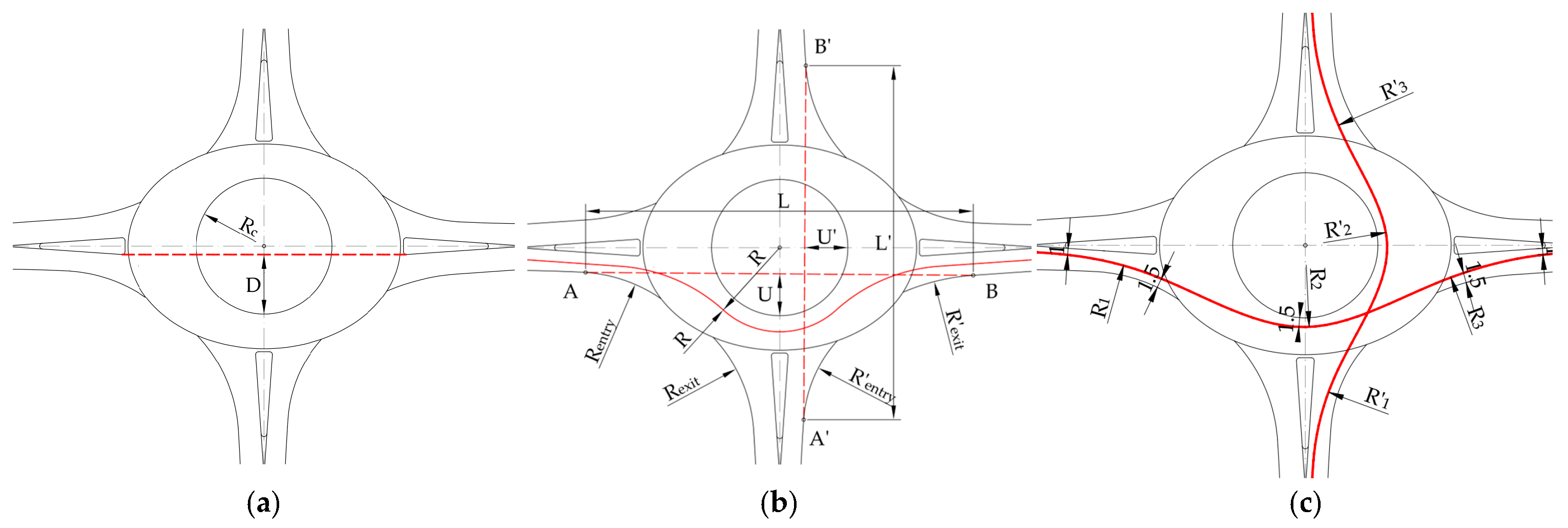
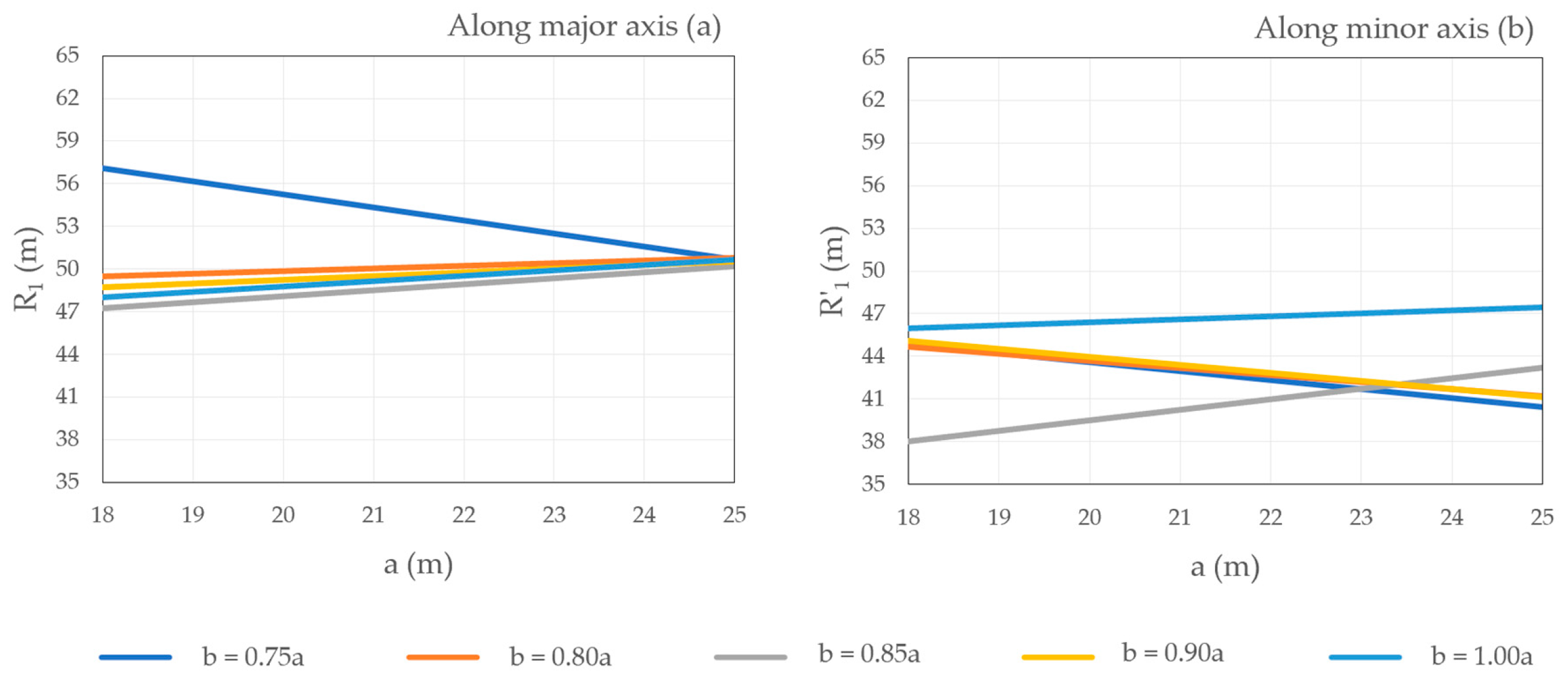
  • the entry path radii (R1 and R′1), which are the minimum radii on the fastest through paths before the entrance line;
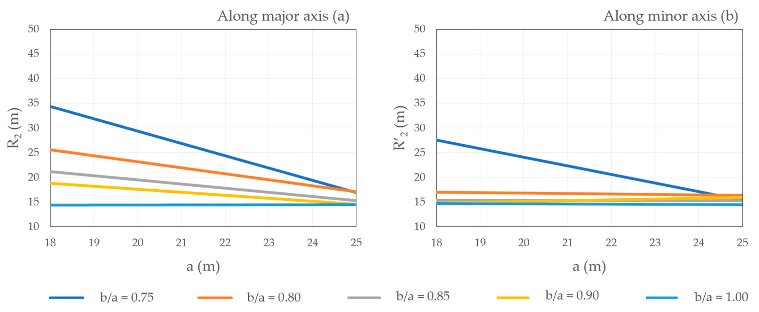
  • the circulating path radii (R2 and R′2), which are the minimum radii on the fastest through paths around the central island; and
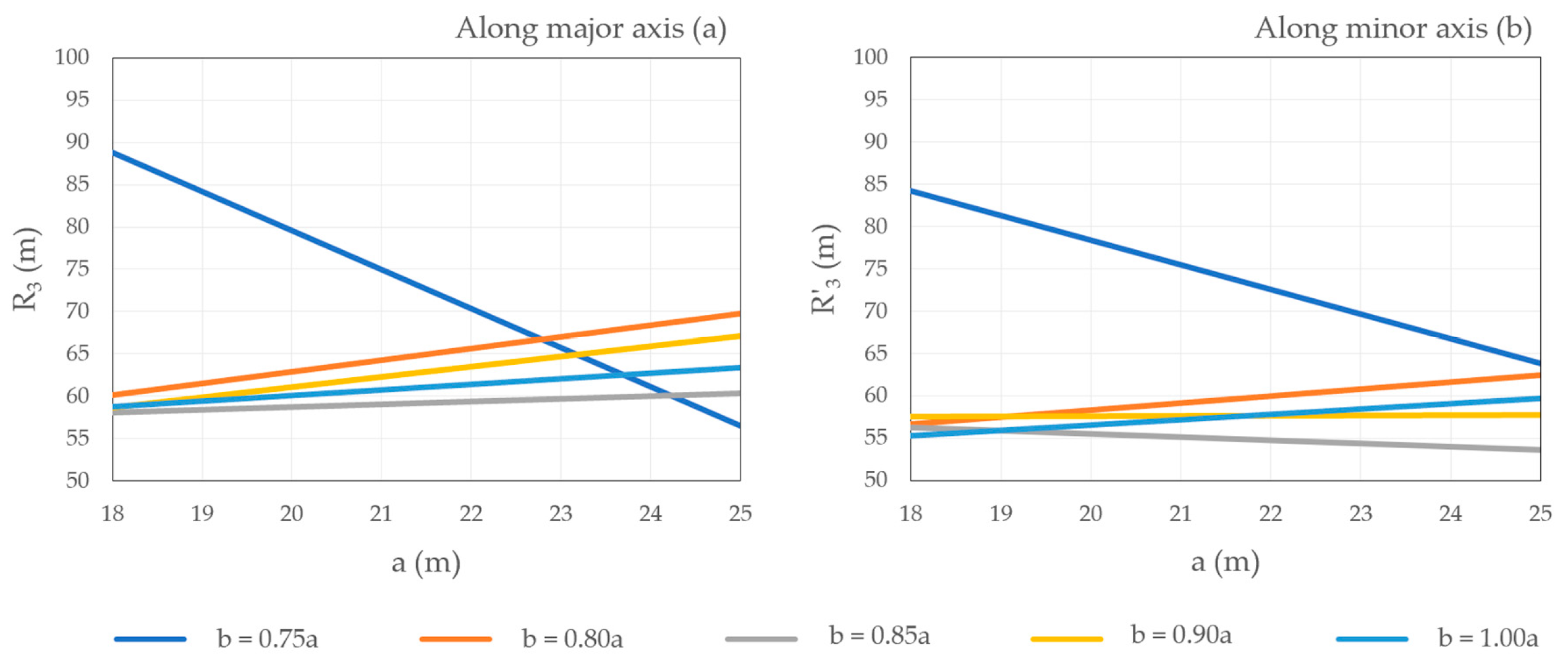
  • the exit path radii (R3 and R′3), which are the minimum radii on the fastest through paths into the exit.
Finally, estimations of vehicle speed based on the speed–radius relationship (3) were conducted for every path radius: the entry speed (V1 along R1 and V′1 along R′1, Figure 3c), the circulating speed (V2 along R2 and V′2 along R′2, Figure 3c), and the exit speed (V3 along R3 and V′3 along R′3, Figure 3c). The resulting relative speed between the consecutive fastest path elements on the entrance path, the path around the central island (V1–V2), and elements on the path around the central island exit path (V3–V2) was also investigated.
Six conditions were investigated for all designed roundabout schemes in the first part of the investigation:
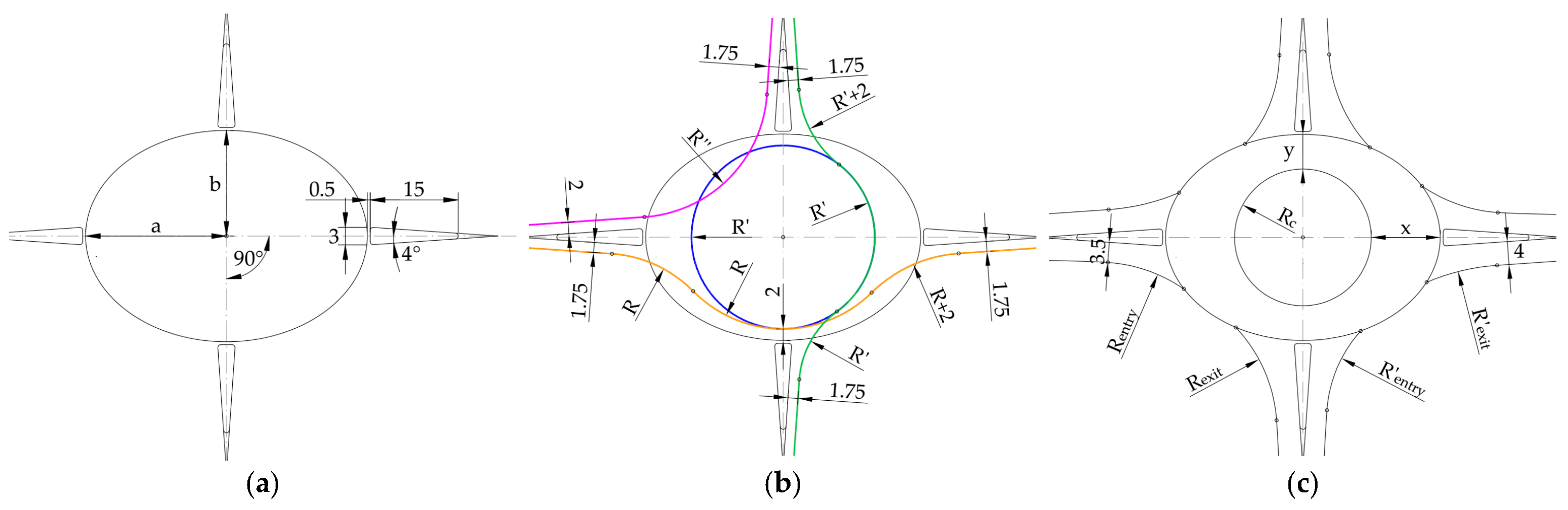
  • Condition 1: circulatory roadway width in single-lane roundabouts (x and y) should be smaller than 5.5 m so that drivers do not use a wide roadway as two lanes and sufficient deflection is achieved [1].
  • Condition 2: circulatory roadway width in the direction of the minor axis (y) should be between 4 and 6 m [22].
  • Condition 3: vehicle path deflection around the central island (D) should be greater or equal to double the entrance width (which is 7.0 m in this investigation) for the roundabout’s design to be deemed satisfactory [10].
  • Condition 4: the deflected vehicle path radius (R1) should not exceed 80–100 m [22].
  • Condition 5: the calculated expected driving speed through the roundabout for the major and minor axis directions (V) should be lower than 35 km/h [14].
  • Condition 6: for vehicles to safely negotiate the roundabout, the maximum relative speed between consecutive fastest path elements (V1–V2 and V3–V2) should not exceed 25 km/h [16].
To meet the requirements of Condition 1 and Condition 2, the second part of the investigation was conducted on 40 modified roundabout schemes. The modification included the definition of the fixed circulatory roadway width along minor axes (y) of 5.5 m. Conditions 3–5 were investigated for these modified roundabout schemes.
To provide the visualization of the dependence between the measured values of the distance between the tangent of the entry radius and the tangent of the exit radius along the major and minor axis (L and L′), the deflection along the major and minor axis (U and U′), personal vehicles’ fastest path radii along the major and minor axis (Ri and R′i, where i = 1–3), and the axis length, these values along both the major and minor axis were plotted for all analyzed roundabout schemes. One hundred simple linear regression models were defined taking the major axis (a) as an independent variable and measured values (L, L′, U, U′, Ri and R′i, where i = 1–3) for different (b/a) relations as dependent variables. It should be emphasized here that these simple linear regression models were not intended for use in the two-geometry roundabout’s design. Their purpose is to provide the visualization of the investigation results in as simple a way as possible.

3. Results

In this section, the results of the investigation and their interpretation are provided. The section is divided into two subsections. In the first subsection, the results of the investigation for 40 roundabout schemes with variable circulatory roadway widths along minor axes (y) that were defined by the resulting design vehicles’ swept paths are presented. In the second subsection, the results of the investigation for 40 roundabout schemes with fixed circulatory roadway widths along minor axes (y = 5.5 m) are presented.

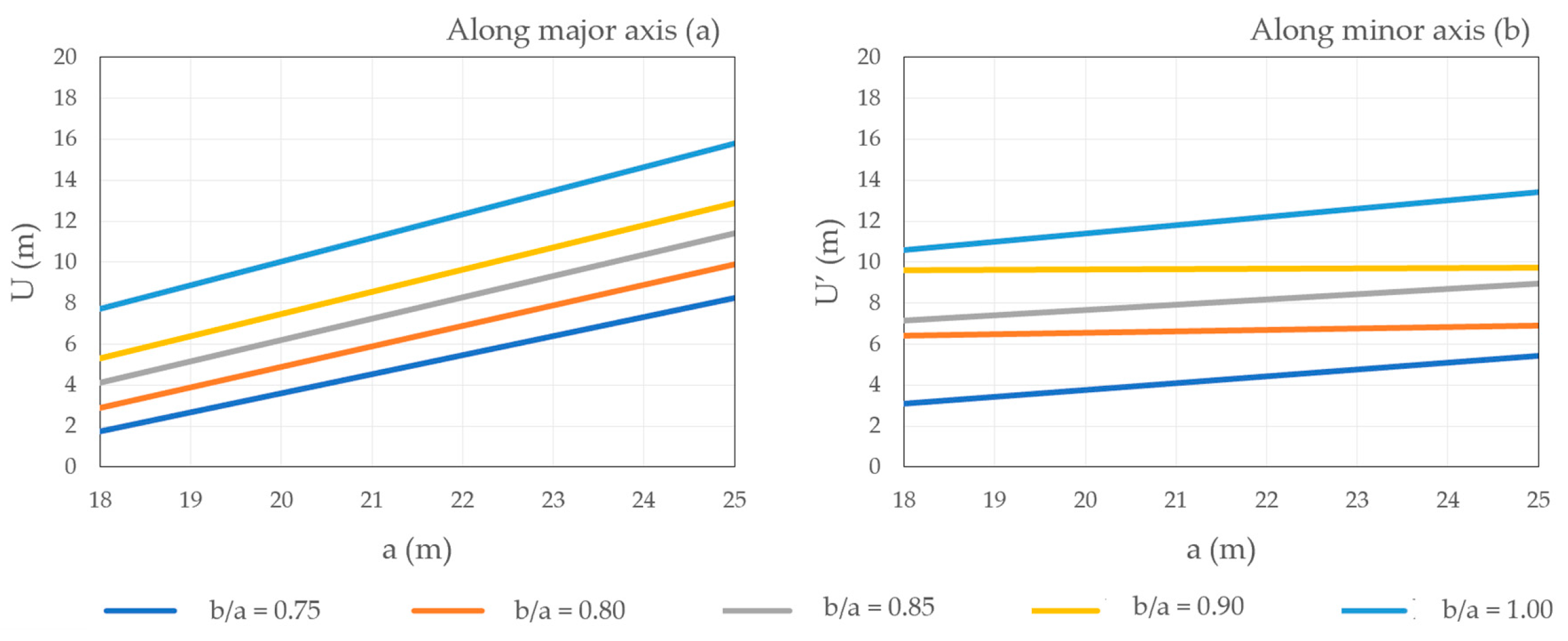
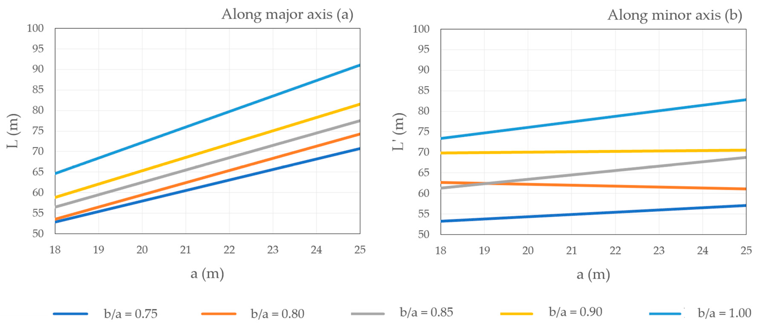
3.1. Roundabout Schemes with Variable (y)

The results of the swept path analyses for the circular movement were the circulatory roadway widths (x) and (y) given in Table 2. The resulting widths along the major axis (x) of analyzed two-geometry roundabout schemes with variable (y) did not meet Condition 1 (x, y < 5.5 m), as they were up to two times wider than the recommended value. This was expected, due to the applied swept path construction. Namely, swept paths for the circular movement were constructed based on a front axle center point path shaped as an arc around the circular central island for a long design vehicle. This arc was constructed with a radius that was offset by 2 m from the roundabout’s minor axis. Only one resulting circulatory roadway width along the minor axis (y) was smaller than 5.5 m—the one for the largest analyzed (a) and (b/a = 0.90). At the same time, Condition 1 was met by three standard geometry roundabout schemes with variable (y) and (a = b = 23–25 m), as shown in Table 2.
Condition 2 (y < 6.0 m) was met by 13 two-geometry roundabout schemes with variable (y). At the same time, Condition 2 was met by seven standard geometry roundabout schemes with variable (y) (Table 2). It can be noted that the resulting circulatory roadway width along the minor axis (y) was inversely proportional to the roundabout size, namely, the major and minor axes (a and b). This was not the case with the resulting circulatory roadway width along the major axis (x), as these values for (b/a = 0.75, 0.80, and 0.85) after initial reduction started to rise (Table 2).
The results of the swept path analyses for the right turn and straight passage were the distances between the tangent of the entry radius and the tangent of the exit radius along the major and minor axes (L and L′) and the deflection along the major and minor axes (U and U′) given in Table 3 and Table 4. It can be noted that these distances and the deflections are proportional to the length of the major axis (a). In general, measured distances between the tangent of the entry radius and the tangent of the exit radius along the major axis (L) are larger than measured distances along the minor axis (L′). The only deviation from this behavior can be noted for a major axis (a) of 24 m and (b/a) of 0.90. At the same time, measured deflections along the major axis (U) are generally smaller than measured deflections along the major axis (U′). The only deviation from this behavior can be noted for a major axis (a) of 18 m and (b/a) of 0.75.
To provide the visualization of the investigation results (given in Table 3 and Table 4 and Appendix A, Table A1 and Table A2) in as simple a way as possible, 50 simple linear regression models were defined taking the major axis (a) as an independent variable and measured values (L, L′, U, U′, Ri, and R′i, where i = 1–3) for different (b/a) relations as dependent variables (Figure 4, Figure 5, Figure 6, Figure 7 and Figure 8). It should be emphasized here that these simple linear regression models were not intended for use in the two-geometry roundabout’s design. The modeled simple linear dependency of the distance between the tangent of the entry radius and the tangent of the exit radius along the major axis (L), the distance between the tangent of the entry radius and the tangent of the exit radius along the minor axis (L′), the deflection along the major axis (U), and the deflection along the minor axis (U′) and the major axis length (a) for roundabout schemes with variable (y) is shown in Figure 4 and Figure 5. It can be noted that the parameters (L) and (U) were significantly influenced by (a) for every designed roundabout scheme with variable (y), while this dependency is less significant for the parameters (L′) and (U′), especially for (b/a = 0.80) and (b/a = 0.90a).
The calculated vehicle path radius (R) and measured personal vehicle fastest paths radii Ri and R′i (i = 1–3) for the variable circulatory roadway width along the minor axis (y) are given in Appendix A, Table A1. The modeled simple linear dependency of the personal vehicle’s fastest path radii (Ri and R′i, where i = 1–3) and the major axis length (a) for roundabout schemes with variable (y) is shown in Figure 6, Figure 7 and Figure 8. It can be noted that:
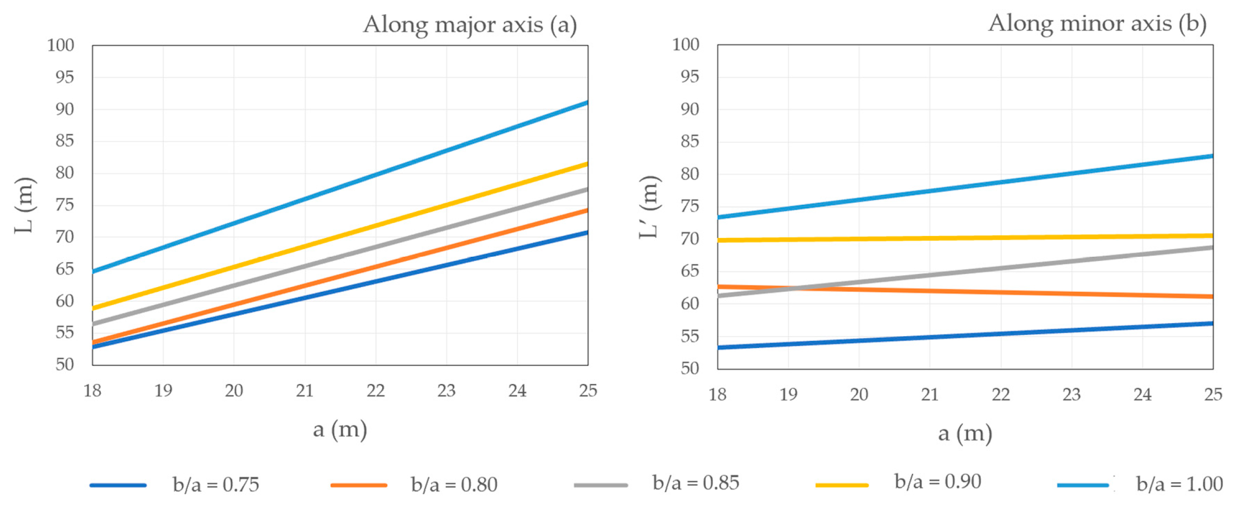
  • radii for (b/a = 0.75) showed the greatest discrepancy caused by large path radii values in roundabouts with the smallest major and minor axes,
  • for (b/a = 1.00), either no influence could be noted, or radii were inversely proportional to (a), and
  • for the rest of the roundabout schemes, either no influence could be noted, or radii were proportional to (a).
Analyses of the vehicle path deflection around the central island have shown that Condition 3 (D > 7.00.m) was met by 88% of the designed two-geometry roundabout schemes with variable (y) and by all standard roundabout schemes with variable (y) (Appendix A, Table A2). Condition 3 was not met by the two-geometry roundabouts with the smallest major and minor axes:
  • major axis (a) of 18 m and (b/a = 0.75, 0.80), and
  • major axis (a) of 19 and 20 m and (b/a = 0.75).
Condition 4 (R1 < 100 m) was not met by one analyzed two-geometry roundabout with variable (y) (Appendix A, Table A1): the one with a major axis (a) of 18 m and (b/a = 0.75) for both directions. This condition was met by all analyzed standard roundabout schemes.
The results of the calculation of the expected driving speed through the roundabout (V) for the major and minor axis directions of each roundabout scheme, which was conducted according to Equation (3), showed that Condition 5 (V < 35 km/h) was not met by all analyzed roundabout schemes with variable (y) (Appendix A, Table A2). The results of the estimation of vehicle speed based on the fastest through paths (V2) showed that these values were over 35 km/h in five analyzed two-geometry roundabout schemes for the major axis direction and three analyzed two-geometry roundabout schemes for the minor axis direction (Appendix A, Table A2). Therefore, this condition was not met for (V2) in the two-geometry roundabouts with the smallest major and minor axes:
  • major axis (a) of 18 m and (b/a = 0.75, 0.80) for both directions,
  • major axis (a) of 19 m and (b/a = 0.75) for both directions, and
  • major axis (a) of 20 and 21 m and (b/a = 0.75) for the major axis direction.
Condition 6, regarding the relative speed between consecutive fastest path elements on exit and around the central island (V3–V2), was not met by 98% of analyzed paths constructed in two-geometry roundabout schemes (Appendix A, Table A2). Regarding the relative speed between consecutive fastest path elements on entry and around the central island (V1–V2), this condition was not met by 6% of analyzed paths. These paths were constructed in two-geometry roundabouts with variable (y) with the smallest major and minor axes (Appendix A, Table A2):
  • major axis (a) of 18 m and (b/a = 0.75) for both directions,
  • major axis (a) of 18 m and (b/a = 0.80) for the major axis direction, and
  • major axis (a) of 19 m and (b/a = 0.75) for the major axis direction.

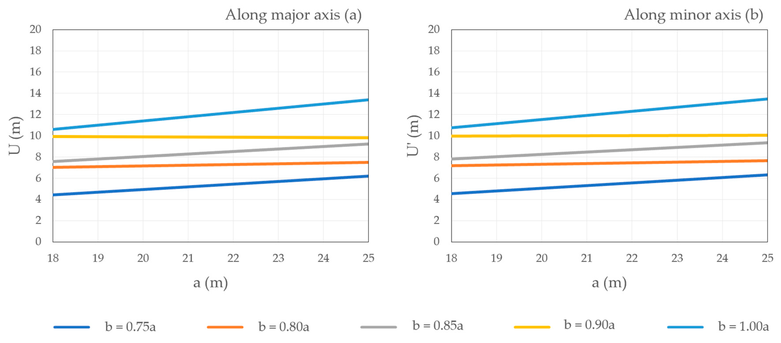
3.2. Roundabout Schemes with Fixed (y)

In the second part of the investigation, the circulatory roadway width along the minor axis (y) was fixed to 5.5 m to meet the requirements of Condition 1 and Condition 2. This resulted in reduced circulatory roadway widths along the major axis (x), as shown in Table 5. It can be noted that the resulting circulatory roadway width along the major axis (x) was proportional to roundabout size, namely, the major and minor axes (a and b).
The results of the swept path analyses for the right turn and straight passage were the distances between the tangent of the entry radius and the tangent of the exit radius along the major and minor axes (L and L′) and the deflection along the major and minor axes (U and U′), given in Table 6 and Table 7. It can be noted that these distances and the deflections are proportional to the length of the major axis (a). Measured distances between the tangent of the entry radius and the tangent of the exit radius along the major and minor axis (L and L′) did not change after the intervention in circulatory roadway width along the minor axis (y). At the same time, measured deflections along the major axis (U) are all smaller than measured deflections along the major axis (U′). It can be also noted that these measured deflections are smaller than the deflections on roundabout schemes with variable (y) and that this difference is inversely proportional to the length of the major axis (a).
To provide the visualization of the investigation results (given in Table 6 and Table 7 and Appendix A, Table A3 and Table A4) in as simple a way as possible, 50 simple linear regression models were defined taking the major axis (a) as an independent variable and measured values (L, L′, U, U′, Ri, and R′i, where i = 1–3) for different (b/a) relations as dependent variables (Figure 9, Figure 10, Figure 11, Figure 12 and Figure 13). It should be emphasized here that these simple linear regression models were not intended for use in the two-geometry roundabout’s design. The modeled simple linear dependency of the distance between the tangent of the entry radius and the tangent of the exit radius along the major axis (L), the distance between the tangent of the entry radius and the tangent of the exit radius along the minor axis (L′), the deflection along the major axis (U), and the deflection along the minor axis (U′) and the major axis length (a) for roundabout schemes with fixed (y) is shown in Figure 9 and Figure 10. It can be noted that compared to the roundabout schemes with variable (y), the parameters (L) and (L′) remained the same and that parameters (U) and (U′) were slightly larger. Their dependency on (a) remained the same.
The calculated vehicle path radius (R) and measured personal vehicle fastest paths radii Ri and R′i (i = 1–3) for the variable circulatory roadway width along the minor axis (y) are given in Appendix A, Table A3. The modeled simple linear dependency of the personal vehicles’ fastest path radii (Ri and R′i, where i = 1–3) and the major axis length (a) is shown in Figure 11, Figure 12 and Figure 13 for roundabout schemes with fixed (y). It can be noted that compared to the roundabout schemes with variable (y), these radii were smaller. Radii for (b/a = 0.75) showed the greatest discrepancy, caused by large path radii values at roundabouts with the smallest major and minor axes.
Analyses of the vehicle path deflection around the central island have shown that Condition 3 (D > 7.00.m) was not met by one analyzed two-geometry roundabout (Appendix A, Table A4): the one with a major axis (a) of 18 m and (b/a = 0.75) for both directions. This condition was met by all analyzed standard roundabout schemes with fixed (y).
Condition 4 (R1 < 100 m) was met by all analyzed two-geometry roundabouts (Appendix A, Table A3) and by all analyzed standard roundabout schemes with fixed (y).
The results of the calculation of the expected driving speed through the roundabout (V) for the major and minor axis directions of each roundabout scheme, which was conducted according to Equation (3), showed that Condition 5 (V < 35 km/h) was not met by all analyzed paths (Appendix A, Table A4). The results of the estimation of vehicle speed based on the fastest through paths (V2) showed that Condition 5 was met by all analyzed paths.
Condition 6, regarding the relative speed between consecutive fastest path elements on entry and around the central island (V1–V2), was met by all analyzed paths (Appendix A, Table A4). This condition regarding the relative speed between the consecutive fastest path elements on exit and around the central island (V3–V2) was not met by 92% of analyzed paths (Appendix A, Table A4).

4. Discussion

The main reasons for the implementation of alternative roundabout types are the disadvantages of standard roundabouts regarding specific location circumstances, resulting in low levels of traffic safety or low capacities as well as negative impacts on the environment and mobility [20,21,22]. According to [22], the main advantages of two-geometry roundabouts are: (1) they occupy less space than standard modern roundabouts, (2) they are easily passable by long vehicles due to their variable circulatory roadway width, and (3) they ensure low vehicle speed because the required personal vehicle path deflection is created by their circular central island.
The investigation presented in this paper has shown that analyzed two-geometry roundabouts are indeed easily passable by the selected long design vehicle. However, the design vehicles’ swept paths used in the roundabout design resulted in extremely large circulatory roadway widths along the major axis (x), ranging from 7.95 to 12.25 m. This could result in personal car drivers trying to use this wide circulatory roadway as multiple lanes, thus reducing traffic safety. Circulatory roadway widths along the minor axis (y), ranging from 5.45 to 7.35 m, were mostly wider than the recommended values of 5.5 m [1] and 6.0 m [22]. These wide circulatory roadways should be avoided, but at the same time, the circulatory roadway must allow the unobstructed passage of long vehicles. The solution is to reduce circulatory roadway width to an appropriate size by introducing truck aprons in the roundabout design. A truck apron is a paved edge of the central island raised relative to the circulatory roadway and constructed with a greater cross slope to deter car drivers from crossing it, thus providing greater safety on roundabouts. In the second part of the investigation, the circulatory roadway width along the minor axis (y) was fixed to 5.5 m to meet the requirements of Condition 1 and Condition 2. This intervention in the initial roundabout schemes reduced the circulatory roadway widths along the major axis (x) and increased deflection around the central island, which is favorable in terms of traffic safety and speed reduction.
The position of the right carriageway edge entry and exit radii (Rentry, Rexit, R′entry, and R′exit, Figure 1c), designed according to the design vehicles’ swept paths, resulted in values of the expected driving speed through the roundabout (V) higher than the recommended 35 km/h [14] in every analyzed roundabout scheme, including the standard roundabouts. These differences were especially pronounced for two-geometry roundabout schemes with smaller major axis (a) values (up to 16 km/h on schemes with (a) of 18 m). Here, it should be noted that this recommended speed limit at roundabouts is conservative compared to the ones given in roundabout design guidelines and regulations used worldwide. For example, Swiss and American guidelines limit the speed to 40 km/h, and French and Italian guidelines to 50 km/h [19]. At the same time, the CROW model (Equation (3)), used in this investigation for the estimation of vehicle speed, results in higher speed values compared to the FHWA model given in [13], which includes superelevation and side friction factors [16,19].
According to [2,8,9,13,27], consistency between the speeds of various movements within the intersection can help to minimize the crash rate between conflicting traffic streams. In the first part of the investigation, 94% of the analyzed paths constructed for the two-geometry roundabout schemes met the requirement for a maximum relative speed on entry (V1–V2), while only 1 (2%) of the analyzed paths met the requirement for a maximum relative speed on exit (V3–V2). For roundabouts that did not meet these requirements, lower speed for the fastest entering and exiting movements should be provided. It is relatively simple to reduce the speed for the fastest entering movements in single-lane roundabouts. Possible options are the introduction of a truck apron (thus adjusting the design vehicle’s swept path and designed entry width/radii parameters) or shifting the approach alignment to the left. Shifting the approach alignment to the left would increase the speed for the fastest exiting movements. Therefore, the issue of relative speed was addressed by fixing the circulatory roadway widths (y) to 5.5 m in the second part of the investigation. This intervention completely fixed the issue of maximum relative speed on entry (V1–V2); however, 92% of the analyzed paths at the exit did not meet the condition of maximum relative speed (V3–V2 < 25 km/h).
To provide deeper insight into the impact of two-geometry roundabouts on traffic safety, the relative speeds between conflicting traffic streams and between consecutive geometric elements in personal vehicles’ fastest paths will be investigated further. The investigation will be conducted on the initial two-geometry roundabout schemes with fixed (y) that will be fitted with truck aprons. These truck aprons will be designed according to the conditions of personal vehicles’ path deflection around the central island and will be at least 1 m wide. Truck aprons will also help reduce the relative speed on the entry and exit, as they will influence the design of the right carriageway edge, reducing and shifting the entry and exit radii (Rentry, Rexit, R′entry, and R′exit, Figure 1c) closer to the outer edge of the circulatory roadway. The expected driving speed through the roundabouts will be estimated by a procedure that includes superelevation and side friction factors. Furthermore, designed two-geometry roundabout schemes will be compared with standard single-lane roundabouts according to their capacity and the surface they occupy. The roundabouts’ capacity will be determined according to the regression Swiss Bovy model, which considers the joint influence of geometric parameters on the capacity [28].

5. Conclusions

The investigation presented in this paper aimed to determine two-geometry roundabouts’ speed reduction capabilities and to investigate consistency between consecutive geometric elements in personal vehicles’ fastest through paths. The investigation was based on computer simulations and speed estimations conducted on 40 four-legged single-lane roundabout schemes that were designed in the Autodesk AutoCAD software. Roundabout elements were designed according to the swept paths of a tractor with a semi-trailer generated by the computer simulations of vehicle movement using Autodesk Vehicle Tracking 2020 software. Investigated schemes included 32 two-geometry four-legged single-lane roundabouts with a major axis (a) between 18 and 25 m and minor axis (b) between 0.75a and 0.90a and eight standard four-legged single-lane roundabouts with outer radii between 18 and 25 m. For designed roundabout schemes, six conditions referring to the circulatory roadway widths, the vehicle path deflection around the central island, the radius of the deflected vehicle path, the expected driving speed through the roundabout, and the relative speed between consecutive fastest personal vehicle path elements were investigated.
The results have shown that to meet the abovementioned conditions, the two-geometry roundabout design presented in this paper must be adjusted. The adjustment is needed as the required circulatory roadway width and personal vehicle path deflection cannot be achieved due to the conditions of the swept path for the long design vehicle. It can be concluded that truck aprons must be included in the design of two-geometry roundabouts with a major axis between 18 and 25 m. This is essential for achieving sufficient traffic safety, i.e., appropriate circulatory roadway widths, personal car path deflection, and the resulting relative speed on these alternative roundabout types.

Author Contributions

Conceptualization, S.A. and I.M.; methodology, S.A.; formal analysis, S.A., M.A. and I.M.; investigation, S.A. and M.A.; resources, S.A., M.A., I.M. and S.B.; visualization, S.A. and M.A.; writing—original draft preparation, S.A.; writing—review and editing, M.A., I.M. and S.B. All authors have read and agreed to the published version of the manuscript.

Funding

The APC was funded by the University of Zagreb, Program “Support for scientific and artistic research in 2022/2023”, grant number GF21.

Institutional Review Board Statement

Not applicable.

Informed Consent Statement

Not applicable.

Data Availability Statement

Not applicable.

Conflicts of Interest

The authors declare no conflict of interest.

Appendix A

Table A1. Calculated vehicle path radius (R) and measured personal vehicle fastest paths radii Ri and R′i (i = 1–3) for the variable circulatory roadway width along the minor axis (y).
Major AxisMinor AxisMajor Axis Direction (Axis a)Minor Axis Direction (Axis b)Standard Geometry (b = a)
a
(m)
b
(m)
R
(m)
R1
(m)
R2
(m)
R3
(m)
R′
(m)
R′1
(m)
R′2
(m)
R′3
(m)
R = R′
(m)
R1 = R′1
(m)
R2 = R′2
(m)
R3 = R′3
(m)
1813.5048.05130.9240.51371.8245.69150.8634.53315.2629.4745.6614.8567.69
14.4038.7191.7629.7399.7233.8964.3824.93101.60
15.3035.0765.6422.8494.2731.5859.0019.4594.89
16.2033.6159.8419.5888.8630.0448.5418.1292.57
1914.2542.2383.3629.92138.7036.5168.3924.89168.3530.6649.9014.6070.50
15.2036.3865.9422.8396.0330.7852.7618.9381.92
16.1531.9160.2820.7378.9629.4947.9016.0076.77
17.1031.2153.4117.8169.8131.4048.3915.8467.25
2015.0037.0668.1125.21103.9932.1656.3320.84114.3729.3144.6913.4788.76
16.0033.4555.0720.3485.0431.8051.7117.7884.18
17.0031.9453.8218.4371.2628.9847.0017.0074.80
18.0030.0251.1317.1071.3828.7746.9115.5775.42
2115.7539.2759.7724.96157.5529.9449.3317.9279.5930.5143.2914.7488.76
16.8032.0053.3620.3279.4928.4942.2215.1364.06
17.8530.8751.2317.4565.0827.9740.7815.0060.47
18.9026.7547.8317.2957.1226.9243.3716.6866.65
2216.5035.0459.7221.4580.9930.5044.3615.8468.6330.9247.4614.1359.25
17.6032.2253.0420.1773.9329.3547.4414.4558.97
18.7031.3050.2416.9663.6528.8043.7014.8561.35
19.8032.0449.6316.0066.2629.7244.1715.9360.10
2317.2532.7055.5121.7068.3628.9054.5517.1370.0631.8250.0414.2085.30
18.4031.9453.9920.3965.7328.4843.6614.7362.15
19.5530.5747.1216.1160.7328.3542.1115.2557.34
20.7030.6147.7414.9758.5329.3844.6714.6456.25
2418.0033.2754.6120.2272.4328.4043.1615.0154.6632.9152.9514.6965.82
19.2032.0950.1718.4963.0129.7339.8117.9255.36
20.4031.6148.6416.4358.7229.2747.3014.8057.27
21.6031.5945.6215.4260.2732.2950.8914.9858.21
2518.7534.0253.6519.8168.2228.0141.5613.8155.6133.9652.9314.7068.15
20.0032.2149.8818.1760.9128.1048.2014.5153.60
21.2531.3846.1416.9059.8330.6551.8414.6657.81
22.5032.3348.2615.1158.6231.4444.2814.4555.48
Table A2. Investigation results for Condition 3 (D > 7 m), Condition 5 (V > 35 km/h, V2 > 35 km/h), and Condition 6 (V1–V2 < 25 km/h, V3–V2 < 25 km/h) for the variable circulatory roadway width along the minor axis (y).
Major AxisMinor AxisMajor Axis Direction (Axis a)Minor Axis Direction (Axis b)Standard Geometry (b = a)
a
(m)
b
(m)
D
(m)
V
(km/h)
V2
(km/h)
V1–V2
(km/h)
V3–V2
(km/h)
D′
(m)
V′
(km/h)
V′2
(km/h)
V′1–V′2
(km/h)
V′3–V′2
(km/h)
D
(m)
V
(km/h)
V2
(km/h)
V1–V2
(km/h)
V3–V2
(km/h)
1813.504.7514738964.75043478810.540292132
14.405.9464031345.943372238
15.307.2443525367.242332439
16.208.3433324378.341322040
1914.255.8484027475.84537245911.641282434
15.207.0453525377.041322235
16.158.2423424328.240302235
17.109.4413123319.441292231
2015.006.8453724386.84234224512.740272243
16.008.1433322358.142312237
17.009.3423223319.340312033
18.0010.54131223210.540292135
2115.757.7463720567.74031213513.841282041
16.809.1423321339.139291930
17.8510.34131222910.339291929
18.9011.43831202511.438301930
2216.508.7443423328.74129203214.941282329
17.6010.04233213010.040282329
18.7011.34130222911.340292029
19.8012.64230233112.640302028
2317.259.6423421279.64031243116.142282440
18.4011.04233212711.039282030
19.5512.34130212812.339291927
20.7013.64129222813.640282127
2418.0010.54333213010.53929202617.142282532
19.2011.94232212711.940311524
20.4013.34230222713.340282228
21.6014.64229212814.642292428
2518.7511.34333212811.33927202818.243282533
20.0012.84232212612.839282326
21.2514.24130202714.241282528
22.5015.64229232815.641282127
Table A3. Calculated vehicle path radius (R) and measured personal vehicle fastest paths radii Ri and R′i (i = 1–3) for the fixed circulatory roadway width along the minor axis (y).
Major AxisMinor AxisMajor Axis Direction (Axis a)Minor Axis Direction (Axis b)Standard Geometry (b = a)
a
(m)
b
(m)
R
(m)
R1
(m)
R2
(m)
R3
(m)
R′
(m)
R′1
(m)
R′2
(m)
R′3
(m)
R = R′
(m)
R1 = R′1
(m)
R2 = R′2
(m)
R3 = R′3
(m)
1813.5035.5463.8922.5194.8031.2348.4320.9398.9828.1441.4313.5259.55
14.4030.1155.8819.7889.0526.5641.4317.1881.73
15.3030.0252.7117.6268.9827.9943.3414.2963.58
16.2030.3749.4116.3970.0127.2141.3614.7870.97
1914.2532.3661.3820.5481.9728.4442.9816.9980.9629.6645.9514.1760.26
15.2030.7555.4718.2462.7326.2039.8014.7470.03
16.1528.5950.6016.4554.1426.5242.2113.1166.55
17.1029.1749.5415.9663.0429.3843.6813.8356.75
2015.0030.7856.4719.3672.5927.0042.4413.4758.3229.0142.4214.1258.06
16.0029.8651.2418.0960.7928.5342.4514.0355.19
17.0029.6350.2216.5757.2826.9543.5715.3061.64
18.0028.6546.5716.0660.6727.4843.5014.0859.41
2115.7534.1658.6020.6486.7825.7939.6315.6466.7430.0643.5616.1062.28
16.8029.6050.3917.9461.1726.4438.0913.2651.27
17.8529.4144.7816.0756.1926.7037.5612.7953.00
18.9025.7245.4016.2151.7325.9439.0315.8063.38
2216.5031.8958.2419.0163.0327.9039.9213.5252.3430.7646.9414.2658.82
17.6030.3449.8518.4062.1427.7140.9113.3451.08
18.7030.2149.0316.2856.9627.8342.3613.3252.85
19.8031.5048.4716.0159.8829.2243.2414.6153.39
2317.2530.5152.6320.0458.6727.0146.2413.8355.5931.8250.0414.2085.30
18.4030.7751.4418.7160.7527.4940.0413.4255.18
19.5529.9347.0616.7857.5127.7840.0113.0951.75
20.7030.3346.1915.4858.9729.1241.0013.3655.16
2418.0031.6950.6219.4864.3427.1241.8413.3048.8632.9152.9514.6965.82
19.2031.2652.2617.7758.4728.9938.8813.3850.55
20.4031.3147.5116.8856.5729.0046.1413.8152.81
21.6031.5044.5416.1459.3132.2047.4714.7561.02
2518.7532.6752.8418.9260.8626.9738.9213.3449.1133.9652.9314.7068.15
20.0031.6749.8517.8661.1727.6544.5113.8450.82
21.2531.2045.7616.8658.1230.4846.3714.1556.48
22.5032.3348.2615.1158.6231.4444.2814.4555.48
Table A4. Investigation results for Condition 3 (D > 7 m), Condition 5 (V > 35 km/h, V2 > 35 km/h), and Condition 6 (V1–V2 < 25 km/h) for the fixed circulatory roadway width along the minor axis (y).
Major AxisMinor AxisMajor Axis Direction (Axis a)Minor Axis Direction (Axis b)Standard Geometry (b = a)
a
(m)
b
(m)
D
(m)
V
(km/h)
V2
(km/h)
V1–V2
(km/h)
V3–V2
(km/h)
D′
(m)
V′
(km/h)
V′2
(km/h)
V′1–V′2
(km/h)
V′3–V′2
(km/h)
D
(m)
V
(km/h)
V2
(km/h)
V1–V2
(km/h)
V3–V2
(km/h)
1813.506.5443524376.54134184011.439272030
14.407.4413322377.438311736
15.308.3413123308.339282131
16.209.2413022329.239281934
1914.257.3423424337.33931183612.040282230
15.208.2413224278.238281834
16.159.2403023249.238272134
17.1010.14030232910.140282128
2015.008.0413323308.03827212913.040282029
16.009.0403121269.040282027
17.0010.04030222610.038292029
18.0011.04030212811.039282129
2115.758.8433423358.83829173114.041301929
16.809.8403121279.838271926
17.8510.94030202610.938261927
18.9011.93830202311.938291729
2216.509.5423224269.53927202615.041282329
17.6010.64132212710.639272026
18.7011.74130222611.739272127
19.8012.84230222812.840282026
2317.2510.34133212410.33828232816.142282440
18.4011.44132212611.439272028
19.5512.64030202612.639272026
20.7013.74129212813.740272028
2418.0011.04233202711.03927212517.142282532
19.2012.24131222512.240271926
20.4013.44130212513.440272326
21.6014.64230202714.642282329
2518.7511.84232222612.03827192518.243282533
20.0013.04231212713.039282225
21.2514.34130202614.341282328
22.5015.64229232815.641282127

References

  1. Ahac, S.; Dragčević, V. Geometric Design of Suburban Roundabouts. Encyclopedia 2021, 1, 720–743. [Google Scholar] [CrossRef]
  2. Hydén, C.; Várhelyi, A. The effects on safety, time consumption and environment of large scale use of roundabouts in an urban area: A case study. Accid. Anal. Prev. 2000, 32, 11–23. [Google Scholar] [CrossRef] [PubMed]
  3. Fernandes, P.; Teixeira, J.; Guarnaccia, C.; Bandeira, J.M.; Macedo, E.; Coelho, M.C. The Potential of Metering Roundabouts: Influence in Transportation Externalities. Transp. Res. Rec. J. Transp. Res. Board 2018, 2672, 21–34. [Google Scholar] [CrossRef]
  4. Distefano, N.; Leonardi, S. Experimental Investigation of the Effect of Roundabouts on Noise Emission Level from Motor Vehicles. Noise Control Engr. J. 2019, 67, 282–294. Available online: https://hdl.handle.net/20.500.11769/371965 (accessed on 19 July 2023). [CrossRef]
  5. Jandacka, D.; Decky, M.; Hodasova, K.; Pisca, P.; Briliak, D. Influence of the Urban Intersection Reconstruction on the Reduction of Road Traffic Noise Pollution. Appl. Sci. 2022, 12, 8878. [Google Scholar] [CrossRef]
  6. Ziolkowski, R. Roundabouts as an effective tool of traffic management. J. Sustain. Archit. Civ. Eng. 2014, 9, 26–34. [Google Scholar] [CrossRef]
  7. Macioszek, E. The road safety at turbo roundabouts in Poland. Arch. Transp. 2015, 33, 57–67. [Google Scholar] [CrossRef]
  8. Chen, Y.; Persaud, B.; Sacchi, E.; Bassani, M. Investigation of models for relating roundabout safety to predicted speed. Accid. Anal. Prev. 2013, 50, 196–203. [Google Scholar] [CrossRef] [PubMed]
  9. Šurdonja, S.; Dragčević, V.; Deluka-Tibljaš, A. Analyses of maximum-speed path definition at single-lane roundabouts. J. Traffic Transp. Eng. (Engl. Ed.) 2018, 5, 83–95. [Google Scholar] [CrossRef]
  10. Merkblatt für die Anlage von Kreisverkehren, K 10000; FGSV (Forschungsgesellschaft für Strassen-und Verkehrswesen): Köln, Germany, 2006.
  11. Gallelli, V.; Vaiana, R.; Iuele, T. Comparison between simulated and experimental crossing speed profiles on roundabout with different geometric features. Procedia -Social Behav. Sci. 2014, 111, 117–126. [Google Scholar] [CrossRef]
  12. Bastos, S.A.; Seco, A. Trajectory deflection influence on the performance of roundabouts. In Proceedings of the European Transport Conference (ETC) Association for European Transport, Strasbourg, France, 18–20 September 2005. [Google Scholar]
  13. Rodegerdts, L.; Bansen, J.; Tiesler, C.; Knudsen, J.; Myers, E.; Johnson, M.; Moule, M.; Persaud, B.; Lyon, C.; Hallmark, S.; et al. NCHRP Report 672: ROUNDABOUTS: An Informational Guide, 2nd ed.; Transportation Research Board: Washington, DC, USA, 2010. [Google Scholar]
  14. CROW: Eenheid in Rotondes; CROW Publication no.126; CROW: Ede, The Netherlands, 1998.
  15. Bassani, M.; Sacchi, E. Experimental investigation into speed performance and consistency of urban roundabouts: An Italian case study. In Proceedings of the 3rd International Conference on Roundabouts, Transportation Research Board, Carmel, IN, USA, 18–20 May 2011. [Google Scholar]
  16. Ahac, S.; Džambas, T.; Dragčević, V. Review of fastest path procedures for single-lane roundabouts. In Road and Rail Infrastructure IV; Lakušić, S., Ed.; The University of Zagreb Faculty of Civil Engineering: Zagreb, Croatia, 2016; pp. 885–891. [Google Scholar]
  17. Ahmed, H.; Easa, S.M. Multi-Objective Evaluation Model of Single-Lane Roundabouts. Transp. Res. Rec. 2021, 2675, 395–410. [Google Scholar] [CrossRef]
  18. Diachuk, M.; Easa, S.M. Guidelines for roundabout circulatory and entry widths based on vehicle dynamics. J. Traffic Transp. Eng. 2018, 5, 361–371. [Google Scholar] [CrossRef]
  19. Ahac, S. Design of Suburban Roundabouts Based on Rules of Vehicle Movement Geometry. Ph.D. Thesis, University of Zagreb, Zagreb, Croatia, April 2014. [Google Scholar]
  20. Tollazzi, T. Alternative Types of Roundabouts: An Informational Guide, Springer Tracts on Transportation and Traffc; Series editor Roger P. Roess; Springer: New York, NY, USA, 2015; Volume 6. [Google Scholar]
  21. Alozi, A.R.; Hussein, M. Multi-criteria comparative assessment of unconventional roundabout designs. Int. J. Transp. Sci. Technol. 2022, 11, 158–173. [Google Scholar] [CrossRef]
  22. Pratelli, A.; Souleyrette, R.R.; Brocchinia, L. Two-Geometry Roundabouts: Design Principles. Transp. Res. Procedia 2022, 64, 299–307. [Google Scholar] [CrossRef]
  23. Džambas, T.; Dragčević, V.; Bezina, Š.; Grgić, M. Reliability of vehicle movement simulation results in roundabout design procedure based on the rules of design vehicle movement geometry. In Road and Rail Infrastructure VI; Lakušić, S., Ed.; The University of Zagreb Faculty of Civil Engineering: Zagreb, Croatia, 2021; pp. 507–515. [Google Scholar] [CrossRef]
  24. Carrasco, M.S. Turning vehicle simulation: Interactive computer-aided design and drafting application. Transp. Res. Rec. 1995, 1500, 1–11. [Google Scholar]
  25. Ahac, S.; Ahac, M.; Džambas, T.; Dragčević, V. The Design Vehicle Steering Path Construction Based on the Hairpin Bend Geometry—Application in Roundabout Design. Appl. Sci. 2022, 12, 11019. [Google Scholar] [CrossRef]
  26. Stančerić, I.; Dobrica, T.; Ahac, S.; Dragčević, V.; Tenžera, D. Offtracking control requirements for quality roundabout design. In Road and Rail Infrastructure III; Lakušić, S., Ed.; The University of Zagreb Faculty of Civil Engineering: Zagreb, Croatia, 2014; pp. 263–268. [Google Scholar]
  27. Novák, J.; Ambros, J.; Frič, J. How Roundabout Entry Design Parameters Influence Safety. Transp. Res. Rec. 2018, 2672, 73–84. [Google Scholar] [CrossRef]
  28. Čudina Ivančev, A.; Ahac, M.; Ahac, S.; Dragčević, V. Comparison of Single-Lane Roundabout Entry Degree of Saturation Estimations from Analytical and Regression Models. Algorithms 2023, 16, 164. [Google Scholar] [CrossRef]
Figure 1. Roundabout design procedure. (a) Initial scheme; (b) Front axle center point path parameters and elements (path for the circular movement around the central island is shown in blue, path for the right turn is shown in pink, path for straight passage in major axis direction is shown in orange, path for straight passage in major axis direction is shown in green); (c) Final roundabout design elements.
Applsci 13 11816 g001
Figure 2. Design vehicle (Scania R500 LA6x2/4MNA tractor with a generic 13.6 m long and 2.55 m wide trailer).
Applsci 13 11816 g002
Figure 3. Roundabout performance checks. (a) Deflection around the central island (measured between the edge of the central island and the line connecting the right edges of the opposite splitter islands shown in red dashed line), according to [10]; (b) Parameters for the determination of the expected driving speed through the roundabout according to [14] (fastest path is represented by the red solid line, while the distances between the tangent of the entry radius and the tangent of the exit radius are represented by the red dash line); (c) Parameters for the fastest path (represented by the red solid line) analyses according to [16].
Applsci 13 11816 g003
Figure 4. The linear dependency of the distance between the tangent of the entry radius and the tangent of the exit radius (L and L′) and the major axis length (a) for roundabout schemes with variable (y).
Applsci 13 11816 g004
Figure 5. The linear dependency of the deflection (U and U′) and the major axis length (a) for roundabout schemes with variable (y).
Applsci 13 11816 g005
Figure 6. The linear dependency of the entry path radii (R1 and R′1) and the major axis length (a) for roundabout schemes with variable (y).
Applsci 13 11816 g006
Figure 7. The linear dependency of the circulating path radii (R2 and R′2) and the major axis length (a) for roundabout schemes with variable (y).
Applsci 13 11816 g007
Figure 8. The linear dependency of the exit path radii (R3 and R′3) and the major axis length (a) for roundabout schemes with variable (y).
Applsci 13 11816 g008
Figure 9. The linear dependency of the distance between the tangent of the entry radius and the tangent of the exit radius (L and L′) and the major axis length (a) for roundabout schemes with fixed (y).
Applsci 13 11816 g009
Figure 10. The linear dependency of the deflection (U and U′) and the major axis length (a) for roundabout schemes with fixed (y).
Applsci 13 11816 g010
Figure 11. The linear dependency of the entry path radii (R1 and R′1) and the major axis length (a) for roundabout schemes with fixed (y).
Applsci 13 11816 g011
Figure 12. The linear dependency of the circulating path radii (R2 and R′2) and the major axis length (a) for roundabout schemes with fixed (y).
Applsci 13 11816 g012
Figure 13. The linear dependency of the exit path radii (R3 and R′3) and the major axis length (a) for roundabout schemes with fixed (y).
Applsci 13 11816 g013
Table 1. Major (a) and minor (b) two-geometry roundabout axes.
ab/a = 0.75b/a = 0.80b/a = 0.85b/a = 0.90
1813.5014.4015.3016.20
1914.2515.2016.1517.10
2015.0016.0017.0018.00
2115.7516.8017.8518.90
2216.5017.6018.7019.80
2317.2518.4019.5520.70
2418.0019.2020.4021.60
2518.7520.0021.2522.50
Table 2. Circulatory roadway widths along the major axis (x) and the minor axis (y) for roundabout schemes with variable (y).
a (m)b/a = 0.75b/a = 0.80b/a = 0.85b/a = 0.90b/a = 1.00
x (m)y (m)x (m)y (m)x (m)y (m)x (m)y (m)x = y (m)
1811.857.3510.607.009.356.658.206.406.05
1911.757.0010.506.709.306.458.106.205.95
2011.756.7510.456.459.256.258.056.055.80
2111.856.6010.456.259.206.058.106.005.75
2211.856.3510.556.159.255.957.955.755.60
2311.956.2010.555.959.255.807.955.655.45
2412.056.0510.655.859.255.657.955.555.45
2512.256.0010.755.759.355.607.955.455.35
Table 3. Distances between the tangent of the entry radius and the tangent of the exit radius along the major axis (L) and deflections along the major axis (U) for roundabout schemes with variable (y).
a (m)b/a = 0.75b/a = 0.80b/a = 0.85b/a = 0.90b/a = 1.00
L (m)U (m)L (m)U (m)L (m)U (m)L (m)U (m)L (m)U (m)
1854.061.8853.512.7757.174.0961.205.3764.637.65
1954.522.5257.263.8758.475.0962.766.4669.668.85
2056.093.5159.264.9262.766.2464.897.5271.4410.14
2162.984.5961.755.9465.207.3162.378.0375.6011.12
2263.135.5165.326.8968.838.3174.119.8079.1512.32
2364.026.3768.387.9270.859.3174.8010.7583.3613.55
2467.997.3471.448.8675.2110.4078.9011.8387.4414.62
2571.668.2074.339.8077.2711.3082.5312.8891.6615.79
Table 4. Distances between the tangent of the entry radius and the tangent of the exit radius along the minor axis (L′) and deflections along the minor axis (U′) for roundabout schemes with variable (y).
a (m)b/a = 0.75b/a = 0.80b/a = 0.85b/a = 0.90b/a = 1.00
L′ (m)U′ (m)L′ (m)U′ (m)L′ (m)U′ (m)L′ (m)U′ (m)L′ (m)U′ (m)
1851.481.7050.412.8655.534.4357.745.3964.637.65
1951.922.7752.983.9956.665.2563.516.6269.668.85
2053.213.7658.715.1859.976.3663.707.6271.4410.14
2154.934.6758.666.1362.147.4263.868.4975.6011.12
2259.625.7862.827.1166.178.4571.229.8579.1512.32
2359.926.3764.858.1368.399.4773.3810.8683.3613.55
2463.197.6069.249.1272.4410.5580.4012.0487.4414.62
2565.058.4169.349.9776.8611.5481.5713.0291.6615.79
Table 5. Circulatory roadway widths along the major axis (x) and the minor axis (y) for roundabout schemes with fixed (y).
a (m)b/a = 0.75b/a = 0.80b/a = 0.85b/a = 0.90b/a = 1.00
x (m)y (m)x (m)y (m)x (m)y (m)x (m)y (m)x = y (m)
1810.005.509.105.508.205.507.305.505.50
1910.255.509.305.508.355.507.405.505.50
2010.505.509.505.508.505.507.505.505.50
2110.755.509.705.508.655.507.605.505.50
2211.005.509.905.508.805.507.705.505.50
2311.255.5010.105.508.955.507.805.505.50
2411.505.5010.305.509.105.507.905.505.50
2511.755.5010.505.509.255.508.005.505.50
Table 6. Distances between the tangent of the entry radius and the tangent of the exit radius along the major axis (L) and deflections along the major axis (U) for roundabout schemes with fixed (y).
a (m)b/a = 0.75b/a = 0.80b/a = 0.85b/a = 0.90b/a = 1.00
L (m)U (m)L (m)U (m)L (m)U (m)L (m)U (m)L (m)U (m)
1854.063.3453.514.2757.175.2461.206.2764.638.20
1954.524.0257.265.0758.476.0462.767.1669.669.30
2056.094.7659.265.8762.766.9964.898.0771.4410.30
2162.985.6961.756.6965.207.8662.378.5375.6011.37
2263.136.3665.327.5468.838.7674.1110.0579.1512.42
2364.027.0768.388.3770.859.6174.8010.9083.3613.55
2467.997.8971.449.2175.2110.5578.9011.8887.4414.62
2571.668.7074.3310.0577.2711.4082.5312.8891.6615.79
Table 7. Distances between the tangent of the entry radius and the tangent of the exit radius along the minor axis (L′) and deflections along the minor axis (U′) for roundabout schemes with fixed (y).
a (m)b/a = 0.75b/a = 0.80b/a = 0.85b/a = 0.90b/a = 1.00
L′ (m)U′ (m)L′ (m)U′ (m)L′ (m)U′ (m)L′ (m)U′ (m)L′ (m)U′ (m)
1851.483.5550.414.3655.535.3757.746.2964.638.20
1951.924.2752.985.1956.666.2063.517.3269.669.30
2053.215.0158.716.1359.977.1163.708.1771.4410.30
2154.935.9258.666.8862.147.9763.868.9975.6011.37
2259.626.6362.827.7666.178.9071.2210.1079.1512.42
2359.927.0764.858.5868.399.7773.3811.0183.3613.55
2463.198.1569.249.4772.4410.7080.4012.0987.4414.62
2565.058.9169.3410.2276.8611.6481.5713.0291.6615.79
Disclaimer/Publisher’s Note: The statements, opinions and data contained in all publications are solely those of the individual author(s) and contributor(s) and not of MDPI and/or the editor(s). MDPI and/or the editor(s) disclaim responsibility for any injury to people or property resulting from any ideas, methods, instructions or products referred to in the content.

