Article

Anthropological Comparative Analysis of CCTV Footage in a 3D Virtual Environment

by
Krzysztof Maksymowicz
1,
Aleksandra Kuzan
2,*,
Łukasz Szleszkowski
1 and
Wojciech Tunikowski
3
1
Department of Forensic Medicine, Wroclaw Medical University, 50-368 Wrocław, Poland
2
Department of Medical Biochemistry, Wroclaw Medical University, 50-368 Wrocław, Poland
3
Faculty of Architecture, Wroclaw University of Science and Technology, 50-317 Wrocław, Poland
*
Author to whom correspondence should be addressed.
Appl. Sci. 2023, 13(21), 11879; https://doi.org/10.3390/app132111879
Submission received: 3 April 2023 / Revised: 24 October 2023 / Accepted: 26 October 2023 / Published: 30 October 2023
(This article belongs to the Special Issue Intelligent Digital Forensics and Cyber Security)

Abstract

:
The image is a particularly valuable data carrier in medical forensic and forensic analyses. One of the analyses, as mentioned above, is to assess whether a graphically captured object is the same object examined in reality. This is a complicated process due to perspective foreshortening, making it difficult to determine the scale and proportion of objects in the frame, as well as the subsequent correct reading of their actual measurements. This paper presented a method for the 3D reconstruction of silhouettes of people recorded in a photo or video, with the aim of identifying these people through subsequent comparative studies. The authors presented an algorithm for dealing with graphic evidence, using the example of the analysis of spatial correlation of the silhouette of the perpetrator of the actual event (recorded via CCTV footage) with the silhouette of the suspect (scanned in 3D in custody). In this paper, the authors posed the thesis that the isometric (devoid of perspective foreshortening) display mode that 3D platforms offer, and the animation of the figure to the desired identical poses, provides the possibility of not only obtaining linear measurements of the person but also of orthophotographic visualization of body proportions, allowing their comparison with another silhouette, which is difficult to achieve in perspective view of the studied image.

1. Introduction

An image is a particularly valuable data source in medico-legal and forensic assessments [1]. Analysis of photographs and video footage from closed-circuit television (CCTV) cameras can provide a lot of key information about the sequence of events during criminal incidents [2,3,4]. One of the primary analyses mentioned above is to assess whether a graphically recorded object corresponds to the object examined in reality.
The examined case showed a real need for verification of the object in the footage. The object in question was the figure of the perpetrator, compared to the actual comparative material for the purposes of personal identification. The comparative material was the body figure of the suspect detained in the case. The incident was an armed robbery at commercial premises. Two CCTV cameras present at the crime scene simultaneously recorded the footage of the incident, showing the figure of the masked perpetrator. In the course of the conducted procedural actions, the suspect was detained and taken into custody. The image of the body figure of the suspect was captured during photo shoots at the place of incarceration. The aim of the analysis was to demonstrate or exclude a correlation between the spatial geometry of the figure of the perpetrator (CCTV video footage) and the figure of the suspect (image recorded during photo shoots at the place of detention).
The main problem and challenge of this type of analysis is to determine the physical dimensions of the examined object whose image was recorded. It is especially complicated when the examined object is in motion and, additionally, its geometry changes during the motion. One such object is the human body, whose shape and size are an indispensable subject of comparative studies [5].
The main parameters for comparing the object with its recorded image are color, geometry, and dimensions. The problem of object analysis in video footage was considered in several aspects. The first was the perspective distortion, which makes it impossible to read the actual measurements in the image. In addition, the footage from CCTV cameras often shows lens distortion characteristic of lenses with short focal lengths, often used in CCTV systems to provide a wider field of view. The lines that are actually parallel become curves in the image of a short focal length camera. This significantly hinders the use of manual descriptive geometry to reconstruct the dimensions of objects in the image.
Another factor is scale reconstruction, i.e., determination of the actual dimensions of the entire scene visible in the video footage or selected objects within that scene. The method of scale reconstruction can be determined using many factors, ranging from the nature of the technical quality of the source material itself (e.g., resolution, glitches, and number of frames) to the specificity of space and objects shown in it (e.g., orthogonal, polygonal, oval, multi-colored, and monochromatic) to its available documentation (e.g., kinetics of the recorder and the number of different shots of the same space).
Another aspect is the measurement of the object visible in the footage or photo. The human figure is a particularly complex object to measure accurately and reliably [6]. The human body is a morphic form; the lack of clear edges or vertices makes measurements difficult, especially when the body is foreshortened, even without lens distortions. The problem of measurement is related to both the difficulty of applying a ruler to the actual material (i.e., a person) and determining the extreme parts of the geometry in the image (Figure 1).
This study proposed a method of extracting 3D models from video footage [7,8] for anthropometric measurements, which gives the opportunity to view and measure such models in a mode devoid of perspective distortion in isometric views, which, in effect, provides meaningful and reliable results of geometric correlation compared to measurements using classical methods [9]. The application of methods contained in this study did not seem to exhibit an active and authoritative reflection of the literature.

Related Works

The authors analyzed the relevant literature. No work was found that would correspond to the methodological steps taken, but there were identical partial elements observed. The authors present their conclusions from this analysis in Table 1.

2. Materials and Methods

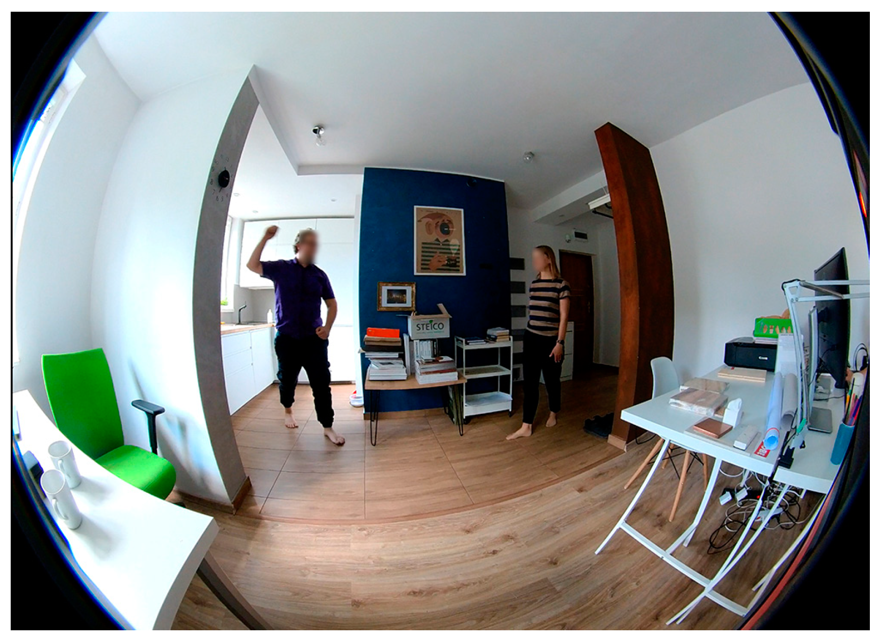
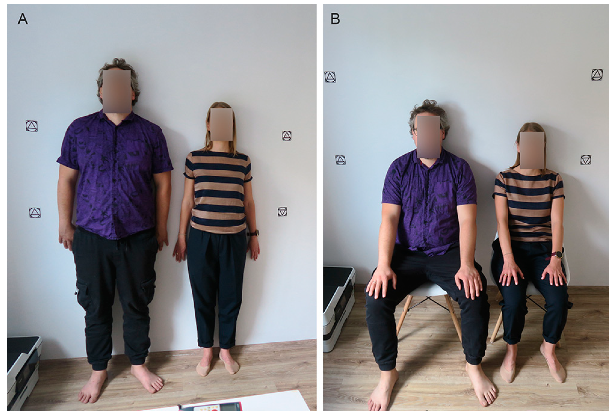
Examination of the evidence was preceded by a series of experimental tests conducted under laboratory conditions. This study was carried out in an enclosed space in daylight without additional artificial lighting. The study participants consisted of two re-enactors of the same age: a man with a height of 184 cm and a woman whose height was 165 cm. This study was conducted in stages. In the first stage, the movement of the re-enactors was recorded in a set space. The footage was taken with a camera that introduced a significant lens distortion (Figure 2). Next, a 3D scan of the re-enactors were made in the studio (Figure 3). The scans were made in various poses (with a view to analyzing changes in the human figure in different poses of the body in motion). The scans were made using the photogrammetric method. Markers, i.e., distinctive points with a set specific and precise distance from each other, were placed in the scan space. The distances were measured using a laser rangefinder. A 3D scan of the scene’s surroundings was then made using Lidar technology with an automatic real-scale reconstruction algorithm (Figure 4). The scan was additionally verified via measurements with a laser finder. Next, all data were imported into an application enabling 3D animation and modeling. Animated characters were created, with anthropometric values corresponding to 3D scans of the re-enactors, and the accuracy of these models was verified based on 3D scans in various poses (Figure 5). The distortion of the recorded video footage was then eliminated based on the created 3D scan (Figure 6), and the parameters and location of the camera that made the recording was reconstructed. This allowed for the creation of the 3D models of the characters seen in the footage (Figure 7). Next, all the obtained figures were brought back to the corresponding ‘zero’ poses, i.e., standing straight ahead, in a relaxed position, with the limbs at rest next to the body. The images were superimposed, and the error limits were analyzed (Figure 8 and Figure 9, Table 2). This procedure, as detailed above, was applied to subsequent re-enactors and subsequent spaces. The authors intend to present the entire validation process in their next publication. After performing validation tests, the authors analyzed the actual evidence. A methodology of this research that is analogous to validation is presented below.
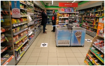
This analysis can be treated as a case study. The materials subjected to this analysis were CCTV camera footage from the crime scene (collected unintentionally) and the images obtained during photo shoots (collected intentionally, with deliberately chosen parameters). The footage from the crime scene comprised two videos from two identical CCTV cameras (BCS camera—model BCS-THC5130IR-V; 1/3”1.4 megapixel CMOS sensor; number of pixels 130(H) × 1049(V); video frame rate 25/50/fps/720p; shutter speed 1/3 s–1/0000 s; sensitivity 0.01 Lux/F1.2(AGC ON); 0 Lux(IR on); lens 2.7–12 mm; angle of view 105.5°–32.9°) (Figure 10). Therefore, the videos were characterized by similar technical parameters (the image is well lit, in color, with a relatively high resolution). The cameras used lenses with a short focal length, which resulted in a curvature of the parallel lines in the recorded footage (so-called fisheye distortions) [14]. This is a typical parameter for this category of devices, allowing cameras to obtain a wide field of view. Footage from both cameras captured the entire incident, showing the body figure of the perpetrator and the crime scene room.
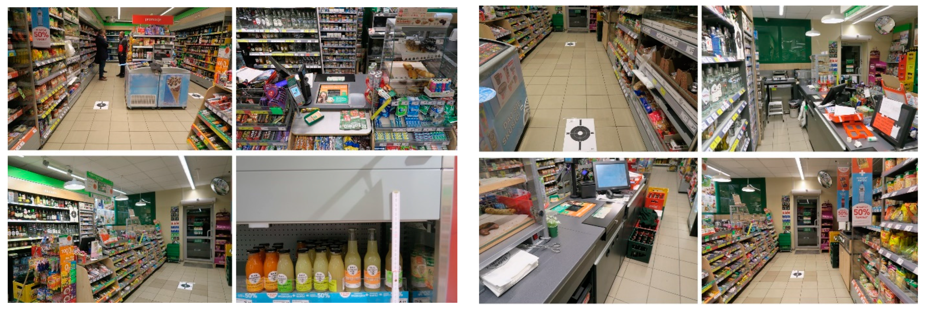
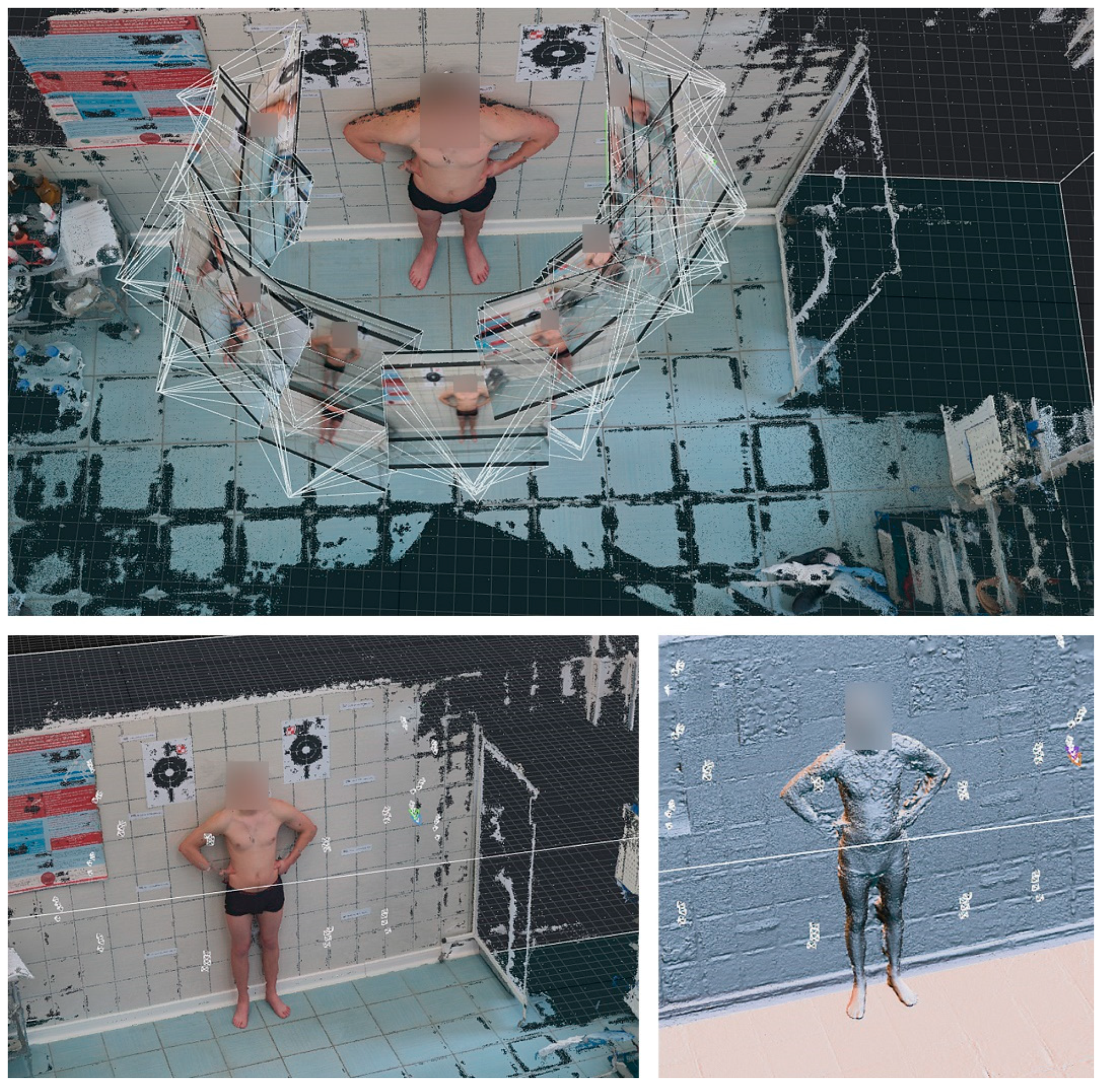
The comparative material was an image of the figure of the suspect, obtained during photo shoots for the purposes of subsequent photogrammetric reconstruction (resulting in a 3D spatial image of the figure of the suspect) [15] (Figure 11) (Camera: Canon G7X; Canon 600D; Tokio, Japan). Additional markers were put on the body of the suspect. Due to the uniformity of skin color and texture, these markers assisted the computational algorithm of the software in generating a 3D model from the photographs. A total of three photo shoots were performed, each in a different body pose of the suspect to locate the center of each joint (areas where the limbs bend) more precisely. Size reference charts and rulers were placed close to the body of the suspect to provide precise measurement points for three-dimensional modeling, enabling the generation of a 3D model of the body figure of the suspect in full-scale size.
The parameters and specifications of the equipment and software used in this study are summarized in Table 3.
Additional material obtained for analysis was an image of the crime scene (commercial premises) (Figure 12). A photo shoot of the crime scene was also made, with the aim of creating a 3D model. Due to the multi-color and diversified arrangement of the site of the crime scene, no additional markers were placed, which usually assist the software algorithm. Next, an architectural inventory of the space was carried out, where spatial measurements were taken with a laser rangefinder.
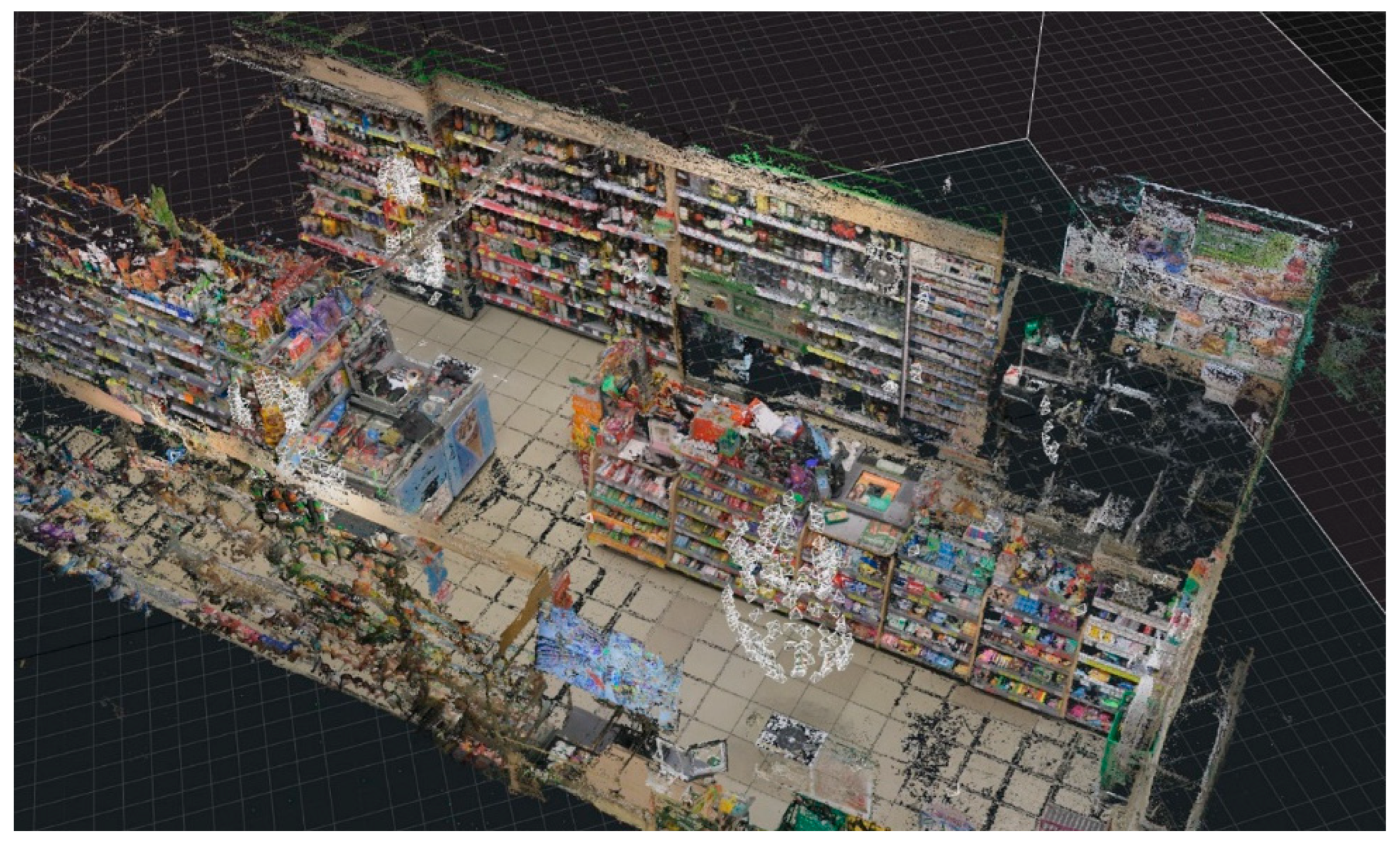
Both evidential videos were shortened to the fragments only showing the key phases of the incident, which were then synchronized, generating pairs of frames depicting the same sequences in time, including the most ergonomically extreme poses of the figure of the suspect. The image distortion was removed with editing software Adobe After Effects (Adobe Inc., San Jose, CA, USA). The converging lines of the linear perspective were straightened in order to subsequently correlate this image with the 3D scene image. The images prepared in this way were processed to better visualize the figure of the perpetrator and were kept for comparison with the 3D image [16]. The subsequent steps were performed in 3D modeling and animation software Autodesk 3D Studio Max, v. 2020 (Autodesk Inc., San Rafael, CA, USA). A 3D model of the crime scene’s surroundings was created and resized to full-scale size based on the dimensions obtained with the rangefinder (Figure 13).
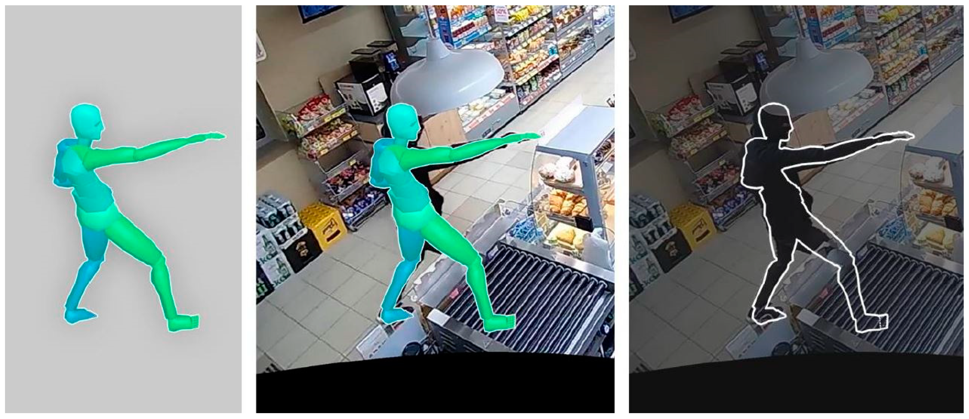
Then, using the application, the lens distortion was eliminated in order to use the resulting background as a pattern for reconstructing the proportions of the silhouette model (Figure 14). As a result, a model of an editable human silhouette was placed in the space of the 3D scene, placed in the place of the figure shown in the recording, and moved from the “zero” pose to the pose corresponding to the recording, and its anthropometric values and dimensions were adjusted to the visible evidence image (Figure 15). Then, in the geometry of the 3D scan of the suspect’s silhouette (Figure 16), a skeleton with the possibility of its animation was placed (Figure 17).
Then, the spatial position of the cameras was reconstructed based on frames from the video recording and a computer application. Virtual cameras in the 3D model of the event space made it possible to observe the model from the same position as the surveillance camera recording the evidence image. Then, animations were made to return to the “zero pose”, allowing for comparisons with another silhouette.
Finally, the reconstructed 3D models of the silhouettes of the perpetrator (reconstructed based on the video image in terms of the reconstructed 3D camera and scale via a 3D scan of the scene) and the suspect were imported and obtained via reconstructions based on 3D scans of their bodies. Images of the silhouettes of both models in different isometric shots, free of perspective and lens distortions, were compared.
The summary of the methodology was made tabular (Table 4 and Table 5) and graphically (Figure 18).
Table 4. Summary of the research materials used.
Research Material
ThumbnailDescriptionPurpose
1.Applsci 13 11879 i001Two video recordings showing the crime scene of the incident and the figure of the perpetrator in different poses.
It contains information about the anthropometric values of the perpetrator (image of body proportions, but impossible to correlate or read at this stage due to the lack of video scale and distorted proportions resulting from the used focal length of the lens).
Evidence for comparative studies.
Reconstruction of a virtual camera corresponding to the CCTV camera from which the 3D scene will then be observed in real scale (point two of the table in question).
2.Applsci 13 11879 i002The physical site of the incident.Creation of a 3D scan, which is the scene for the virtually reconstructed CCTV camera (point one of the table in question) to recreate the figure of the perpetrator in the correct proportions and dimensions.
3.Applsci 13 11879 i003The physical outline of the suspect’s body.Creation of a 3D scan to study the correlation of spatial geometry in a 3D environment.
Table 5. Summary of the computer applications used.
Computer Software
IconDescriptionApplication:
1.Applsci 13 11879 i004ADOBE PHOTOSHOP (v. 24.0)—a comprehensive graphics program for creating and editing raster graphics.Single image editing, descriptions, and metrics.
2.Applsci 13 11879 i005ADOBE AFTER EFFECTS (v.24.0)—comprehensive video editing and animation software.Video editing and frame extraction.
3.Applsci 13 11879 i006AGISOFT METASHAPE (v.1.5.0)—a program for converting photographs into a textured 3D model (photogrammetry).Creating a 3D scan of the crime scene and creating a 3D scan of the figure of the suspect.
4.Applsci 13 11879 i007PIXEL FARM PFTRACK (v. 4.1.5)—software that allows for the extraction of camera movement and spatial position based on video footage, as well as analysis and correction of lens distortions.Reconstruction and correction of video lens distortion resulting from the short focal length of the CCTV camera.
5.Applsci 13 11879 i008AUTODESK 3D STUDIO MAX (v. 2020)—software offering a wide range of tools for creating, handling, and editing 3D models and animations in a scalar system.Integration of all elements in 3D space, transforming them to the real scale, animation of poses of the figures, and spatial correlation of the human figures.
Figure 18. Graphical visualization of the procedure’s methodology.
Applsci 13 11879 g018
  • A—evidence, video footage of the incident with the figure of the perpetrator.
  • B—photographic and measurement documentation of the crime scene after the incident.
  • C—photographic and measurement documentation of the figure of the suspect (comparative material).
  • A1—obtaining evidence from the case files—video sequence.
  • A2—selection of critical fragments of the video sequence (radically different poses of the perpetrator in order to obtain a meaningful reading of the proportions) and export of selected frames.
  • A2r—result of the A2 process, selected individual images (frames).
  • A3—correction of the lens distortion (necessary for image interpretation in a 3D application scene) and reconstruction of camera positions and parameters.
  • A3r—result of the A3 process, reconstructed 3D camera corresponding to the camera of the evidential video footage.
  • B1—post-incident visit to the space of the crime scene.
  • B2—placement of markers at the crime scene and taking control measurements with a laser rangefinder for the subsequent calibration of the point cloud of a photogrammetric 3D scan.
  • B3—performance of a photo shoot, with a view to subsequent photogrammetric reconstruction.
  • B3r—result of the B3 process, a sequence of images for photogrammetric reconstruction.
  • B4—creating a 3D scan scale reconstruction based on markers and rangefinder measurements.
  • B4r—result of the B4 process, a colored scalar point cloud.
  • AB1—synthesis of the results of work on material A and material B; import of the reconstructed 3D camera to the 3D scan space.
  • AB1r—synthesis of work on material A and material B, placing the evidence in the point cloud of the 3D camera, allowing for examinations of the 3D scan from the viewpoint of the evidential footage camera. Insertion of an editable human figure into the space of the 3D scene, positioning this figure in the location of the figure seen in the footage, animation from the ‘zero pose’ to the pose corresponding to the footage, and adjusting its anthropometric values and dimensions to the visible evidential image. Animation returning to the zero pose for comparison with another human figure. Export of the figure prepared in this way for further work in the 3D environment.
  • C1—visual examination of the suspect.
  • C2—placement of markers at the site of scanning of the suspect and on their body, taking control measurements with a laser rangefinder for the subsequent calibration of the point cloud of a photogrammetric 3D scan.
  • C3—performance of a photo shoot, with a view to subsequent photogrammetric reconstruction.
  • C3r—result of the C3 process, a sequence of images for photogrammetric reconstruction.
  • C4—creating a 3D scan scale reconstruction based on markers and rangefinder measurements.
  • C4r—result of the B4 process, a colored scalar point cloud.
  • C5—insertion of an editable human figure in the space of the 3D model of the figure of the suspect, animation from the zero pose to the pose corresponding to the pose from the 3D scan, and adjusting its anthropometric values and dimensions to this scan. Animation returning to the zero pose for comparison with another human figure. Export of the figure prepared in this way for further work in the 3D environment.
  • ABC1—synthesis of the results of work on materials A, B, and C. Import of the reconstructed 3D models of two figures—that of the perpetrator (reconstructed to scale using the substituted 3D scan of the crime scene based on the video footage from the viewpoint of the reconstructed 3D camera) and that of the suspect (obtained via reconstruction based on a 3D body scan). Comparison of results, involving views of the figures of both models from various isometric viewpoints, free of perspective and lens distortions.

3. Results

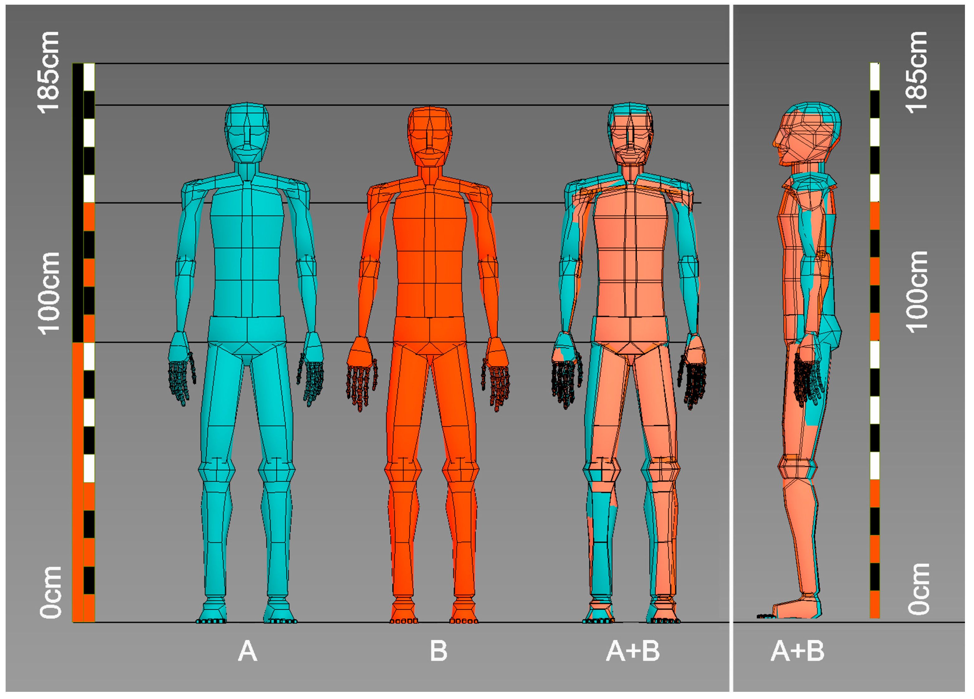
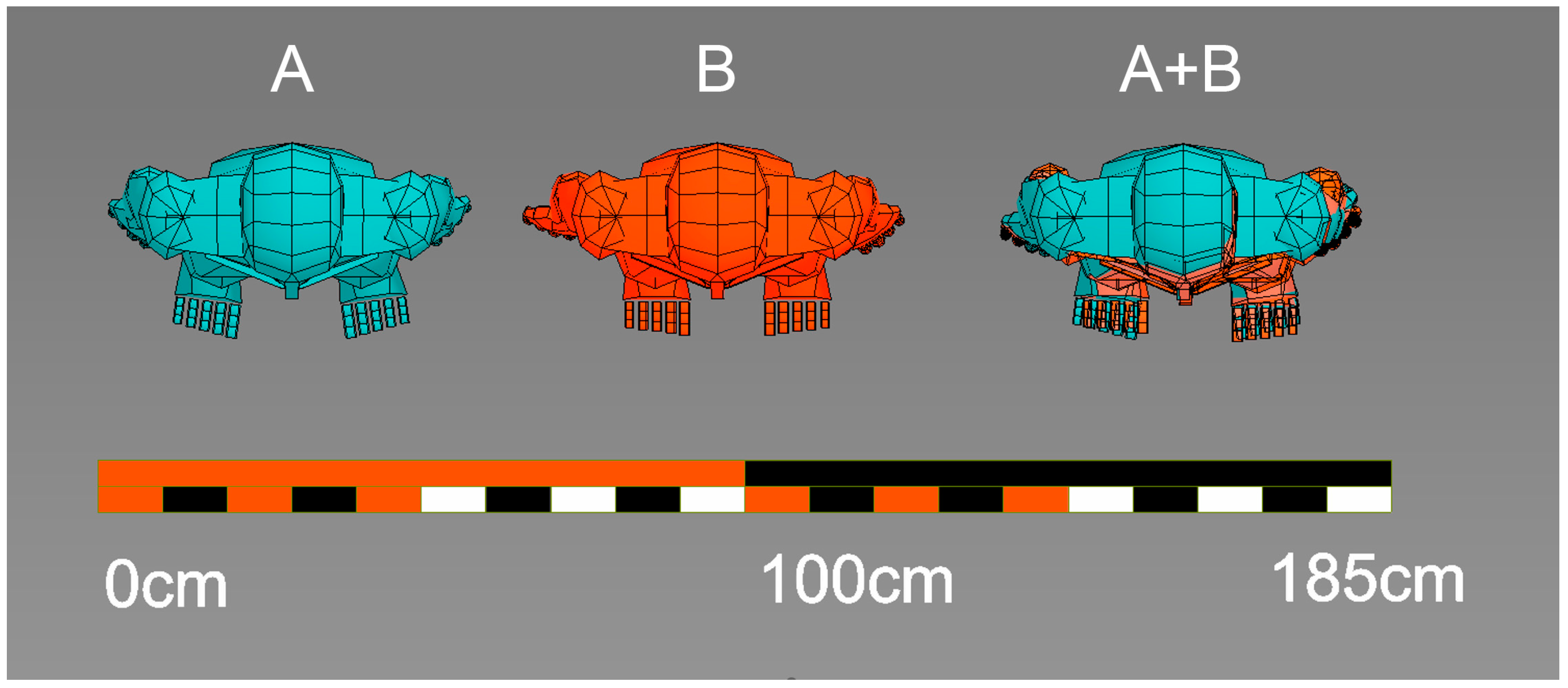
The result of this research is a virtual juxtaposition of two 3D models of silhouettes. The first silhouette is a reconstructed silhouette of the perpetrator based on the evidence recording. The second is the silhouette of the suspect, based on a 3D scan of a real person. These silhouettes were brought to identical poses in animation and juxtaposed on a real scale (both silhouettes with the correct dimensions and proportions resulting from the reconstruction). Then, isometric images of both silhouettes standing next to each other were created, and these images were superimposed on each other under cross-talk mode. The sequences were created from several shots, each time maintaining the isometric display mode, i.e., without perspective distortions, thus enabling a real comparison of proportions and sizes. The silhouettes were presented in frontal, side, and top views, and in axonometric views (Figure 19, Figure 20 and Figure 21). These images gave the opportunity to not only assess the scalar correlation, i.e., the overall dimensions of the figures shown, but also to compare and check the proportions of the bodies, i.e., the lengths of individual anatomical parts of the body (feet, shanks, thighs, torso, forearms, arms, head, etc.).

4. Discussion

Video image analysis is widely used in forensic medicine and criminology [10]. One such application is the search for spatial correlations between human figures [17]. Generally, the features that are verified include the height [18,19], size, and shape of the head and face [20], as well as the foot size. Assessment of the head size is generally problematic and imperfect due to the presence of hair and, in some cases, headgear, as well as the used method and format of video recording (limiting the quality and resolution). The same problem applies to determining the size of feet; they are often foreshortened, which prevents accurate readings of their actual size. In the described case, the verifiable elements were all the characteristics discussed above—dimensions of the limbs, head, and torso. Therefore, proportions were measured on the whole figure and not on its fragments, which minimized the measurement error associated with the low resolution of the video image. This method also identifies the same type among people of similar heights and foot sizes but with different lengths and proportions of the limbs, which makes it more precise and effective (Figure 21). Determination of the complete set of anthropometric measurements may be the focus of subsequent analyses, e.g., studies of gait [21].

4.1. Problems and Issues Underlying 3D Reconstruction of Objects Based on Their Images

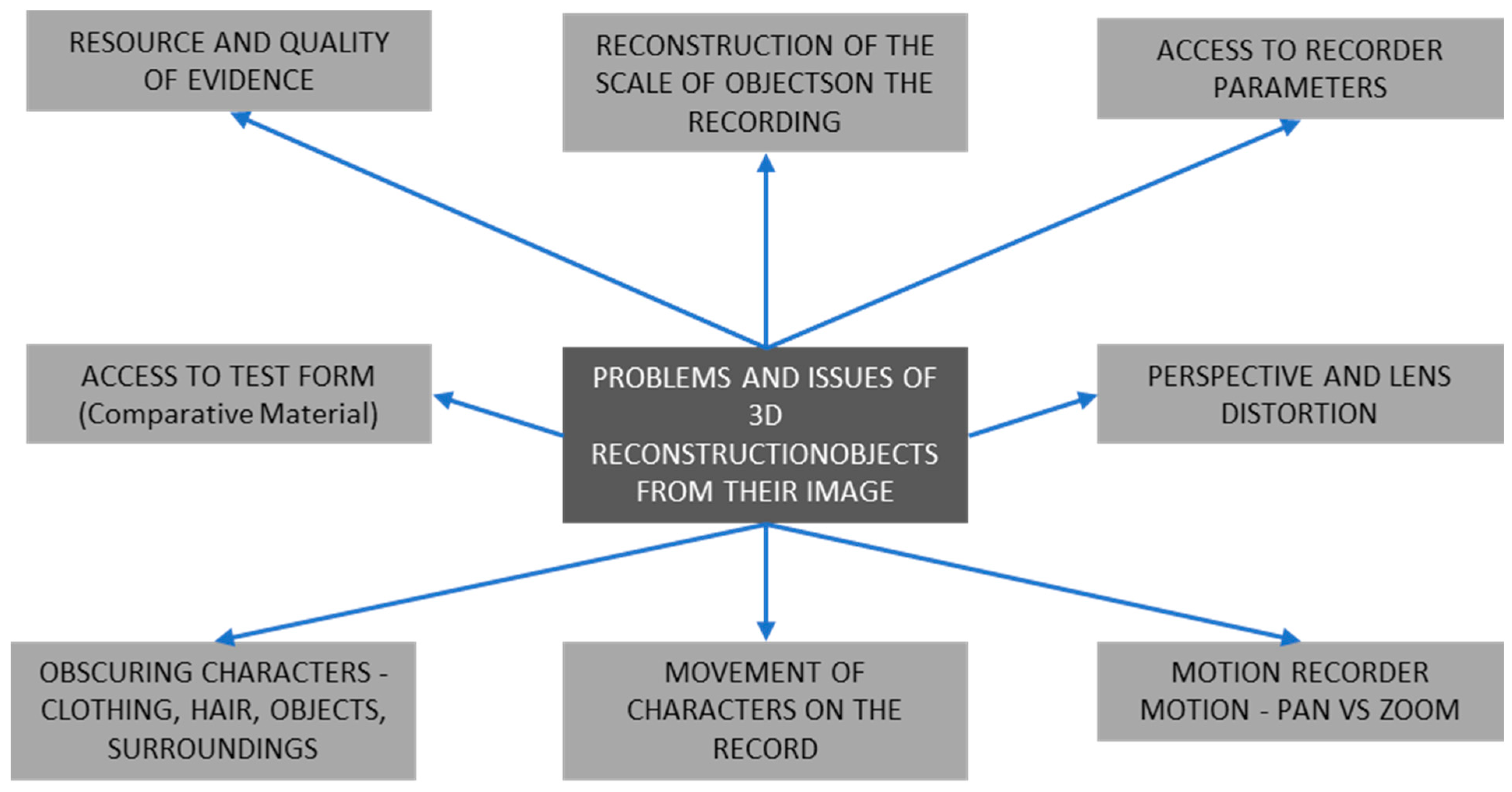
This paper presents a method of the 3D reconstruction of objects visible on the recording in order to analyze their geometry and dimensions for further comparative research. There are a number of issues associated with this process, which are outlined in the graph below (Figure 22) and described later in this/current section.

4.2. Resource and Quality of Evidence

Based on the amount of evidence, the authors understood the number of shots showing the examined object at the same time. The test could have been carried out even on a single static image of the tested object (i.e., one photo), but each subsequent shot had a positive effect on the accuracy of the reconstruction and the exclusion of possible anomalies (for example, specific positions of the object in relation to the camera). A multitude of static shots, as well as video recordings, will improve the results. In turn, the technical quality of the image has a direct impact on the precision of the results. The parameters of image quality include resolution, color distortion, and glitches that change the geometry of the image (e.g., in digitized scans of video tapes or analog scans of photos). Therefore, a decrease in quality affects the credibility of the reconstruction, and in extreme cases it may also make it impossible to perform the examination. The authors wrote about the direct impact of the decline in quality later in the current section titled measurement error.

4.3. Reconstruction of the Scale of Objects on the Recording

To reconstruct the geometry of an object shown in a video or photo, the dimensions of the accompanying objects in the frame need to be known. The larger the area of the studied space is known, i.e., possible to reproduce in the preserved geometry and scale, the more accurate the reconstruction. Therefore, in the course of this study, a 3D scan of the examined space was made. It should be noted whether the elements have not changed their location in relation to the examined image. Due to this, the authors most likely used fixed points, i.e., the division of floor tiles, the shelves of the serving counter, etc. However, it is not always possible to access the scene of the event to perform a 3D scan on a real scale. In such situations, reference objects need to be sought with known dimensions in the frame. These include objects of repetitive production, e.g., elements of equipment, products, household appliances, and cars, as well as construction elements, paving stones, standard bricks, and others. The presence of such elements on the video recording gives an opportunity to reconstruct the scale of the entire space and, as a result, also determine the dimensions of the examined object [11].

4.4. Access to Recorder Parameters

Knowing the type of camera that was used to capture the image is important. The algorithms of most photogrammetric applications take into account data such as focal length, sensor type, and recording resolution. Knowing these data not only makes it easier to reconstruct the position and parameters of the virtual camera, but also affects the accuracy of this reconstruction. Having knowledge about the camera model, you can also possess it physically, and perform a perspective distortion test by performing the so-called distortion charts, i.e., record distortions of the checkerboard resulting from the curvature of the lens sensor. This element greatly facilitates further work. However, not having the above-mentioned data does not make it impossible to perform further stages of this study.

4.5. Access to Test Form (Comparative Material)

The test can be performed based on measurements of the real figure, as in the presented case, by performing its 3D scan. However, this is not an absolute condition. An analogous algorithm can be used when comparing figures in two video recordings or even two photographs. However, it is strongly recommended, if such access is available, to perform a 3D scan in several different poses. This gives knowledge about the actual system of proportions in motion. If the figure in the comparative recording is also in motion and changes its poses, performing a 3D scan is not necessary from the point of view of reconstruction, but it significantly shortens the process of recreating the 3D silhouette, which affects the economy of the examination.

4.6. Perspective and Lens Distortion

Perspective distortion is the main problem in the reading of dimensions, as well as in the correct assessment of the geometry of objects in the image [12]. Virtually every image recorded with classic photo/video recorders is burdened with a foreshortening. Thus, there is no method to precisely read the dimensions of an object in an image without applying the reconstruction operations. Even if there is a ruler with a scale mark in the frame of the image, the fact of foreshortening will effectively falsify the reading. Therefore, the authors indicated the method of comparing objects in an environment free of perspective distortions, i.e., in a 3D environment (in which it is possible to look at the object in an isometric way). There are manual methods of relating selected lengths and proportions in the image to others [22], consequently giving a chance for primitive measurement, but they lose their effectiveness when there are no objects with edges or parallel planes in the image (as it is not possible to determine the directions of perspective convergence) and when the image is additionally burdened with lens distortion, distorting the lines that are actually parallel to the image [23]. Therefore, in the authors’ opinion, it is necessary to use both algorithms that correct lens distortion and foreshortening.

4.7. Problem with Reading Character Proportions—Clothing, Goodness, and Hair

In the preparation of 3D models of the silhouettes of both the perpetrator and the suspect, both clothing and brawn were omitted. Comparative material may potentially be analyzed in different clothing, and the nutritional status of the suspect may change over time (he may gain or lose weight dramatically from the time of the event until the time of registration of the comparative material). Thus, the lengths separated by the joints of the body were analyzed. In order to precisely and reliably recreate the skeleton based on the scan of the suspect, it was created based on several 3D models of the silhouette in various poses, including bent limbs. In this way, the nodes (places of bending the limbs) were correctly located in space, corresponding to their position of the actual location of the joints in the body. The correctness of the spatial topography of the location of the perpetrator’s joints on the evidence recording was also verified. The positioned figure was verified and corrected in several extremely different poses, showing the full range of motion of the character’s limbs.

4.8. Character Movement in the Recording

As described in the point above the current section, the movement of the figure in the recording is a factor that increases the accuracy and reliability of the reconstruction. The movement of a figure in the frame, depending on its specificity, provides valuable information. A character changing the position of his body, i.e., moving his limbs, squatting, bending, etc., provides material for the analysis and localization of joint and skeletal topography. This is the basis for a faithful and precise reconstruction of the anthropometric values of the figure, and thus the basic pattern for comparison with other people. Movement in the frame space, on the other hand, provides two more types of data. The first is the step spacing, which may be subjected to a separate anthropometric analysis (due to the examination, it is possible to precisely measure the spacing of steps, their length, and recreate the layout and trajectory on an isometric horizontal projection) [13]. The second change of position into the frame is verified through the correctness of the reconstruction of the camera optics. In other words, if the virtual 3D silhouette has the correct proportions and size in front of the frame, as well as in its depth, it proves the compatibility of all data and the correct reconstruction of the camera and the character. This means that the character is ready to undergo correlation analysis with the reference material.

4.9. Motion Recorder Motion—Pan vs. Zoom

Camera movement can be beneficial rather than undesirable. Three aspects of camera movement can be considered here—two analog and one optical/digital. When the camera is located in one position but rotates, changing the observation point, in principle it can be said that this movement does not provide new desired data, but is also not detrimental to the reconstruction (until we do not lose sight of the examined object). If the camera changes its position, this can be beneficial for reconstruction, as it automatically provides multiple shots of the same space from different positions as it moves. Both the space that will serve as a set of reference objects for the reconstruction of the scale, as well as subsequent shots of the examined object itself, which was a human figure in this study, greatly increases the chances of a precise reconstruction. The third movement of the camera is the movement resulting from the change in focal length, the so-called zoom. This is an undesirable phenomenon and is disturbing, and sometimes makes reconstructions impossible. If we do not have data about the recorder, including the value of the zoom range, the camera reconstruction applications may not be able to cope with such a recording, which, in turn, will prevent further work.

4.10. Measuring Error Analysis

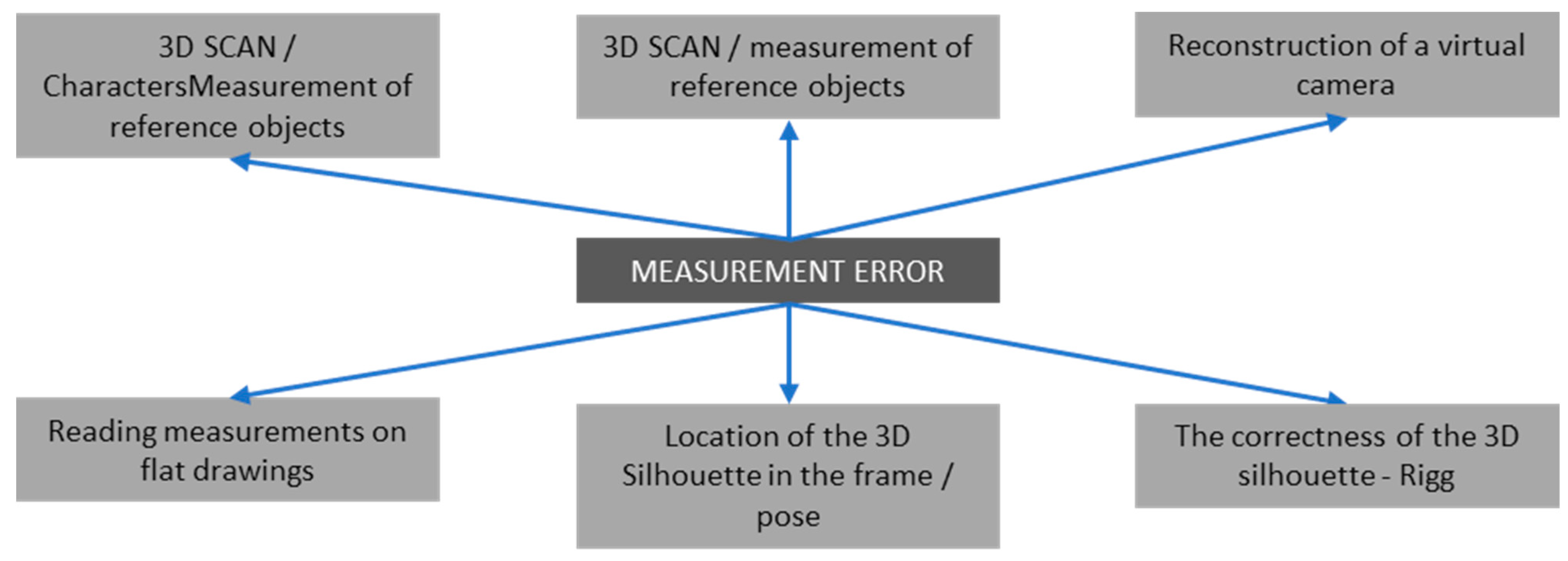
In the process of the 3D reconstruction of objects from their images, errors can be made that affect the final result. The main ones are shown in the diagram below (Figure 23) and described later in this section.

4.10.1. 3D Scan/Measurement of Reference Objects

If the scan is not performed with a scanner with its own scale measurement algorithm, care should be taken to ensure that the reference measurements on the markers are correct. This affects the scaled 3D scan and the final effect of the reconstruction.

4.10.2. Reconstruction of a Virtual Camera

An incorrectly reconstructed camera may affect the final size of the 3D scene. This is a critical stage of reconstruction, so all possible data should be used, such as camera data; if there is physical access to it, then construct distortion charts, and then visually verify the compatibility of the 3D scene elements from the scan with the image taken using the reconstructed camera.

4.10.3. Location of the 3D Silhouette in the Frame/Pose

Positioning, animating, and determining the length of the limbs is a manual process. This is performed by the animator based on the placed image of the character; hence, the measurement error may result at this point from the individual assessment of the graphic material. The figure shows the ranges in exemplary measurement errors in the real scale of the 3D scene to visualize the dependence of an incorrect selection of limb sizes.

4.10.4. The Correctness of the 3D Silhouette—Rigg

If only the research material allows for it, it is essential to verify the proportions of the created 3D silhouette in at least a few poses, including shots of the comparative material, as one image can provide an incorrect assessment of the location of the limbs in space. The result may still be the correct figure in terms of scale and dimensions, but the proportions of the reproduced figure may be distorted.

4.10.5. Reading Measurements on Flat Drawings

Finally, prepared flat charts, providing isometric views of the figures, can also be misread and interpreted; hence, every researcher using this study should become familiar with the rules of reading the linear scale. The authors of the study, on the other hand, should avoid errors in applying linear scale metrics or measurement grids on the study’s boards.

4.11. Additional/Other Notes

Similarly, an unlimited amount of comparative material can theoretically be analyzed. Virtually any images or real objects can be combined. However, at the current stage, the methodology is a conglomerate of several different techniques, uses different computer applications, and leaves a large field of work burdened with the subjectivity of the animator. The authors undertook preliminary work on the creation of a computer application that could combine the considered algorithms and constitute an integral tool for exactly this type of analysis, and the extraction of selected 3D models for the purposes of subsequent analyses.
When interpreting the results of the correlation test, it should be kept in mind that the analysis, in terms of the process, is exclusionary in the absence of correlations between the comparative material and the evidence. However, if a correlation is shown, the above does not necessarily mean that the suspect is the perpetrator, but only indicates a high probability of analogy in the structure and size of the body of the perpetrator and the suspect.

5. Conclusions

CCTV camera recordings are potentially a useful and effective material for medico-legal and forensic assessments. The analysis in the 3D environment allows for determining the anthropometric features of people captured on the recorded visual material, taking into account their height, body build, relative proportions of the limbs and trunk, sized pelvic and shoulder girdles, and the geometry of the head, face, and feet. We conclude that the analysis of anthropometric features in the 3D environment should be carried out on the basis of the image of the body in various sequences of its arrangement. At the same time, changing elements in geometry, such as hair, clothing, and body structure, should be excluded. Thus, the contours do not have to be the same when trying to correlate the analyzed figures.
What distinguishes the authors’ work from research in related fields is the comparison of reconstructed objects in a 3D environment. The isometric (without foreshortening) display mode offered by 3D platforms, and the animation of the characters to the desired identical poses, not only makes it possible to measure the character linearly, but also to correctly assess and examine the correlation of the proportions of the whole body, which is difficult to obtain in the perspective view of the frame video or photo.
To summarize, a comparative analysis in a 3D environment of the evidence image from the CCTV camera and the comparative image obtained using various techniques (photos, videos, and 3D scans) allows for proving or excluding the existence of correlations between physical features and dimensions of space, human silhouettes, and objects.

Author Contributions

Conceptualization, K.M.; methodology, Ł.S. and W.T.; software, Ł.S. and W.T.; formal analysis, K.M.; investigation, K.M., Ł.S. and W.T.; resources, K.M. and Ł.S.; data curation, A.K.; writing—original draft preparation, K.M. and W.T.; writing—review and editing, Ł.S., A.K.; visualization, W.T.; supervision, K.M.; project administration, K.M. All authors have read and agreed to the published version of the manuscript.

Funding

This research received no external funding.

Institutional Review Board Statement

Not applicable.

Informed Consent Statement

Written consent has been obtained from the from the court prosecutor to use the material on the condition that identifying features are not disclosed.

Data Availability Statement

Data supporting reported results can be received from the first author after a reasonable request (without identifying the suspect).

Conflicts of Interest

The authors declare no conflict of interest.

References

  1. Milliet, Q.; Delémont, O.; Margot, P. A forensic science perspective on the role of images in crime investigation and reconstruction. Sci. Justice 2014, 54, 470–480. [Google Scholar] [CrossRef] [PubMed]
  2. Rahman, S.Z.A.; Abdullah, S.N.H.S.; Hao, L.E.; Abdulameer, M.H.; Zamani, N.A.; Darus, M.Z.A. Mapping 2D to 3D forensic facial recognition via bio-inspired active appearance model. J. Teknol. 2016, 78, 121–129. [Google Scholar] [CrossRef]
  3. Han, I. Car speed estimation based on cross-ratio using video data of car-mounted camera (black box). Forensic Sci. Int. 2016, 269, 89–96. [Google Scholar] [CrossRef] [PubMed]
  4. Arsié, D.; Schuller, B.; Rigoll, G. Multiple Camera Person Tracking in Multiple Layers Combining 2D and 3D Information. In Workshop on Multi-Camera and Multi-Modal Sensor Fusion Algorithms and Multiple Camera P; ECCV: Marseille, France, 2008. [Google Scholar]
  5. Johnson, M.; Liscio, E. Suspect Height Estimation Using the Faro Focus(3D) Laser Scanner. J. Forensic Sci. 2015, 60, 1582–1588. [Google Scholar] [CrossRef] [PubMed]
  6. Mitzel, D.; Diesel, J.; Osep, A.; Rafi, U.; Leibe, B. A fixed-dimensional 3D shape representation for matching partially observed objects in street scenes. In Proceedings of the Proceedings—IEEE International Conference on Robotics and Automation, Seattle, WA, USA, 26–30 May 2015; Institute of Electrical and Electronics Engineers Inc.: Piscataway, NJ, USA, 2015; Volume 2015, pp. 1336–1343. [Google Scholar]
  7. Buck, U.; Naether, S.; Räss, B.; Jackowski, C.; Thali, M.J. Accident or homicide—Virtual crime scene reconstruction using 3D methods. Forensic Sci. Int. 2013, 225, 75–84. [Google Scholar] [CrossRef] [PubMed]
  8. Buck, U.; Naether, S.; Braun, M.; Bolliger, S.; Friederich, H.; Jackowski, C.; Aghayev, E.; Christe, A.; Vock, P.; Dirnhofer, R.; et al. Application of 3D documentation and geometric reconstruction methods in traffic accident analysis: With high resolution surface scanning, radiological MSCT/MRI scanning and real data based animation. Forensic Sci. Int. 2007, 170, 20–28. [Google Scholar] [CrossRef] [PubMed]
  9. Russo, P.; Gualdi-Russo, E.; Pellegrinelli, A.; Balboni, J.; Furini, A. A new approach to obtain metric data from video surveillance: Preliminary evaluation of a low-cost stereo-photogrammetric system. Forensic Sci. Int. 2017, 271, 59–67. [Google Scholar] [CrossRef] [PubMed]
  10. Xiao, J.; Li, S.; Xu, Q. Video-Based Evidence Analysis and Extraction in Digital Forensic Investigation. IEEE Access 2019, 7, 55432–55442. [Google Scholar] [CrossRef]
  11. De Angelis, D.; Sala, R.; Cantatore, A.; Poppa, P.; Dufour, M.; Grandi, M.; Cattaneo, C. New method for height estimation of subjects represented in photograms taken from video surveillance systems. Int. J. Leg. Med. 2007, 121, 489–492. [Google Scholar] [CrossRef] [PubMed]
  12. Liscio, E.; Guryn, H.; Le, Q.; Olver, A. A comparison of reverse projection and PhotoModeler for suspect height analysis. Forensic Sci. Int. 2021, 320, 110690. [Google Scholar] [CrossRef] [PubMed]
  13. Nguyen, N.H.; Hartley, R. Height measurement for humans in motion using a camera: A comparison of different methods. In Proceedings of the 2012 International Conference on Digital Image Computing Techniques and Applications (DICTA), Fremantle, Australia, 3–5 December 2012. [Google Scholar] [CrossRef]
  14. Seckiner, D.; Mallett, X.; Roux, C.; Meuwly, D.; Maynard, P. Forensic image analysis—CCTV distortion and artefacts. Forensic Sci. Int. 2018, 285, 77–85. [Google Scholar] [CrossRef]
  15. Luhmann, T.; Robson, S.; Kyle, S.; Harley, I. Close Range Photogrammetry: Principles, Techniques and Applications; Whittles Publishing: Dunbeath, UK, 2011. [Google Scholar]
  16. Jameson, J.; Zamani, N.A.; Abdullah, S.N.S.H.; Ghazali, N.N.A.N. Multiple Frames Combination Versus Single Frame Super Resolution Methods for CCTV Forensic Interpretation. J. Inf. Assur. Secur. 2013, 8, 230–239. [Google Scholar]
  17. Bulut, Ö.; Sevim, A. The Efficiency of Anthropological Examinations in Forensic Facial Analysis. Turk. J. Police Stud./Polis Bilim. Derg. 2013, 15, 139–158. [Google Scholar]
  18. Lee, J.; Lee, E.D.; Tark, H.O.; Hwang, J.W.; Yoon, D.Y. Efficient height measurement method of surveillance camera image. Forensic Sci. Int. 2008, 177, 17–23. [Google Scholar] [CrossRef] [PubMed]
  19. Hoogeboom, B.; Alberink, I.; Goos, M. Body height measurements in images. J. Forensic Sci. 2009, 54, 1365–1375. [Google Scholar] [CrossRef] [PubMed]
  20. Buck, U.; Naether, S.; Kreutz, K.; Thali, M. Geometric facial comparisons in speed-check photographs. Int. J. Leg. Med. 2011, 125, 785–790. [Google Scholar] [CrossRef] [PubMed]
  21. Bouchrika, I.; Goffredo, M.; Carter, J.; Nixon, M. On using gait in forensic biometrics. J. Forensic Sci. 2011, 56, 882–889. [Google Scholar] [CrossRef] [PubMed]
  22. Criminisi, A.; Zisserman, A.; Van Gool, L.J.; Bramble, S.K.; Compton, D. New approach to obtain height measurements from video. Investig. Forensic Sci. Technol. 1999, 3576, 227–238. [Google Scholar] [CrossRef]
  23. Tosti, F.; Nardinocchi, C.; Wahbeh, W.; Ciampini, C.; Marsella, M.; Lopes, P.; Giuliani, S. Human height estimation from highly distorted surveillance image. J. Forensic Sci. 2022, 67, 332–344. [Google Scholar] [CrossRef] [PubMed]
Figure 1. Body measurement issues in perspective (A,C) versus isometric view (B,D). The “?” points shows distance that can not be measured (because of perspective view focal distortion). The “X” and “Y” points shows distance that can be measured (because ortographic view is geometrically undistorted).
Applsci 13 11879 g001
Figure 2. Video footage of the re-enactors in motion with a high-lens distortion effect.
Applsci 13 11879 g002
Figure 3. Photo session for further photogrammetry scans. (A)—standing postures, (B)—seated postures. In the background, the black and white markers stickers can be seen on the wall. The distances between markers are precise and were measured with a laser finder. Markers positions will be used for a reconstruction scale and proportions validation.
Applsci 13 11879 g003
Figure 4. Lidar 3D scan of the surroundings with a dimensions check.
Applsci 13 11879 g004
Figure 5. Reconstruction of the figures of the re-enactors based on a 3D scan. (A) Point cloud, (B) point cloud with 3D models, and (C) 3D models.
Applsci 13 11879 g005
Figure 6. Elimination of the distortion of the recorded video footage with 3D scan data. (A) A distorted image (curved lines), and an (B) undistorted image (straight lines).
Applsci 13 11879 g006
Figure 7. Three-dimensional reconstruction of the characters seen in the video footage. 3D model Shading: (A)—Wire frame, (B)—Solid.
Applsci 13 11879 g007
Figure 8. Correlation between the results and analysis of measurement error (measurement). (A) Man figure (3D scan reconstruction—green volume, and video reconstruction—yellow outline). (B) Woman figure (3D scan reconstruction—blue volume, and video reconstruction—red outline).
Applsci 13 11879 g008
Figure 9. Correlation between the results and analysis of measurement error (dimension grid).
Applsci 13 11879 g009
Figure 10. Fragments of the monitoring recording at the scene. (A) View from the first camera. (B) View from the second camera.
Applsci 13 11879 g010
Figure 11. Comparative material—photo shoot of the suspect at the place of incarceration.
Applsci 13 11879 g011
Figure 12. Additional material—photo shoot of the crime scene.
Applsci 13 11879 g012
Figure 13. Creating a 3D scan of the event site.
Applsci 13 11879 g013
Figure 14. Lens distortion removal. Physically straight lines are curved on lens distorted image (examples indicated with yellow color). The same lines after lens distortion removal are straight (indicated with blue color).
Applsci 13 11879 g014
Figure 15. Determining the spatial silhouette in the frame of the reconstructed camera with a background without lens distortion.
Applsci 13 11879 g015
Figure 16. Creating a 3D scan of a suspect’s silhouette.
Applsci 13 11879 g016
Figure 17. Anthropometric adjustment locating a suspicious skeleton capable of 3D animation in a 3D scan.
Applsci 13 11879 g017
Figure 19. Imposition of isometric images of reconstructed silhouettes. Silhouette “A” (blue)—a figure reconstructed from a video recording. Silhouette “B” (red silhouette) was reconstructed based on a 3D scan of the suspect. “A + B”—graphical imposition of visualizations of both silhouettes on a real scale. Frontal and side views.
Applsci 13 11879 g019
Figure 20. Imposition of isometric images of reconstructed silhouettes. Silhouette “A” (blue)—a figure reconstructed from a video recording. Silhouette “B” (red silhouette) was reconstructed based on a 3D scan of the suspect. “A + B”—graphical imposition of visualizations of both silhouettes on a real scale. Top view.
Applsci 13 11879 g020
Figure 21. Imposition of isometric images of reconstructed silhouettes. Silhouette “A” (blue) a figure reconstructed from a video recording. Silhouette “B” (red silhouette) was reconstructed based on a 3D scan of the suspect. “A + B”—graphical imposition of visualizations of both silhouettes on a real scale. Axonometric view.
Applsci 13 11879 g021
Figure 22. Problems and issues underlying the 3D reconstruction of objects from their images.
Applsci 13 11879 g022
Figure 23. Factors that may generate a measurement error.
Applsci 13 11879 g023
Table 1. Related works analysis.
Paper or Publication Closest to the Field:Common Elements:Research Potential beyond the Analyzed Position:
Johnson, M.; Liscio, E.
Suspect Height Estimation Using the Faro Focus (3D) Laser Scanner.
J. Forensic Sci. 2015, 60, 1582–1588, doi:10.1111/1556-4029.12829 [5]
3D-scaling objects based on a 3D scan survey; and lens distortion issue solving solution.
  • 3D comparison model to model—analysis of whole body to body pattern in real scale (not only height but also every body part’s length and joint position).
  • Video 3D analysis in motion (multiple pose use for correct body position).
  • Complex automatized lens distortion solving solution optimized via 3D scan data (correct and precise algorithm of distortion grid analysis and correction).
  • Possibility of reference physical person body pattern analysis.
  • Possibility of video-to-video or picture-to-picture 3D comparison from different sources (different recorder, time, quality, and resolution).
Xiao, J.; Li, S.; Xu, Q. Video-Based Evidence Analysis and Extraction in Digital Forensic Investigation.
IEEE Access 2019, 7, 55432–55442, doi:10.1109/ACCESS.2019.2913648 [10]
Rich theoretical background of the field.
De Angelis, D.; Sala, R.; Cantatore, A.; Poppa, P.; Dufour, M.; Grandi, M.; Cattaneo, C.
New method for height estimation of subjects represented in photograms taken from video surveillance systems. Int. J. Legal Med. 2007, 121, 489–492, doi:10.1007/S00414-007-0176-4. [11]
New method of object measurements in pictures; no 3D scan data involved; and no lens distortion issue solving solution.
Liscio, E.; Guryn, H.; Le, Q.; Olver, A.
A comparison of reverse projection and PhotoModeler for suspect height analysis.
Forensic Sci. Int. 2021, 320, doi:10.1016/J.FORSCIINT.2021.110690. [12]
New method of objects measurements in pictures; no 3D scan data involved; and lens distortion issue solving solution.
Nguyen, N.H.; Hartley, R.
Height measurement for humans in motion using a camera: A comparison of different methods.
2012 Int. Conf. Digit. Image Comput. Tech. Appl. DICTA 2012 2012, doi:10.1109/DICTA.2012.6411679. [13]
New method of object measurements in pictures; no 3D scan data involved; and lens distortion issue solving solution.
Table 2. Correlation between the results and analysis of measurement error (dimension grid—color coded).
Reconstructed 3D Model:3D Model Color in FiguresOverall Height Measure
(Centimeters)
Overall Measure Error (Percentage)
Man (3D scan)------------------------------------184 cm1.08%
Man (video)------------------------------------182 cm
Woman (3D scan)------------------------------------165 cm1.80%
Woman (video)------------------------------------168 cm
Table 3. A description of the detailed research methodology.
Study stage:Video footage of the re-enactors in motion3D scan of the re-enactors3D scan of the surroundingsReconstruction of the figures of the re-enactors based on a 3D scanReconstruction of the characters seen in the video footageCorrelation between the results and analysis of measurement error
Thumbnail Figure 2Figure 3Figure 4Figure 5Figure 6 and Figure 7Figure 8, Figure 9 and Figure 11
Method Video footagePhotogrammetryLidar3D modeling and animation3D modeling and animation3D modeling and animation
ParticipantsTwo, a man and a womanTwo, a man and a womanNoneNoneNoneNone
EquipmentInsta 360Canon G7XiPhone 14 Pro MaxPersonal computerPersonal computerPersonal computer
SoftwareInsta StudioAgisoft MetashapeiPhone 14 Pro MaxAutodesk 3D Studio MaxAutodesk 3D Studio MaxAutodesk 3D Studio Max
GoalThe video footage is to be the main basis of the reconstruction material (it is to simulate the evidence in analyses at the post-implementation stage of the method)A 3D scan needed to create 3D models of the re-enactors for further correlation of 3D geometry with the figure in the video footage A 3D scan needed to analyze the elimination of lens distortion and reconstruct the real scale of the video footageA 3D reconstruction of the figures to correlate their shapes and dimensions with the subsequently obtained result of video sequence reconstruction A 3D reconstruction of the figures to correlate their shapes and dimensions with the previously obtained result of video sequence reconstructionsSuperimposition of the results in a 3D environment, without perspective distortions, in identical poses—a reliable and complementary comparison of the anthropometric values of the figures
ResultVideo sequenceA three-dimensional real-scale point cloudA three-dimensional real-scale point cloudAnimated 3D modelsAnimated 3D modelsAn interactive 3D scene + flat 2D images
Validation/commentA 360 camera with an ultra-wide angle lens was used to create the real-life conditions of CCTV camerasIn order to validate the results of the correctness of the 3D reconstruction of the re-enactors, markers, with known set distances from each other, were placed in the space of photographs used for subsequent photogrammetric reconstruction. These dimensions were determined with a laser finder.In order to validate the results of the correctness of the 3D reconstruction of the re-enactors, markers, with known set distances from each other, were placed in the space of photographs used for subsequent photogrammetric reconstruction. These dimensions were determined with a laser finder.The correctness of joint locations and limb lengths of the 3D skeleton was validated based on scans of various poses of the re-enactors The reconstruction involved a prepared 3D scene based on the recreated camera of the video footage. The superimposed images were presented on a real scale, and the measurement error was read.
Disclaimer/Publisher’s Note: The statements, opinions and data contained in all publications are solely those of the individual author(s) and contributor(s) and not of MDPI and/or the editor(s). MDPI and/or the editor(s) disclaim responsibility for any injury to people or property resulting from any ideas, methods, instructions or products referred to in the content.