Article

Parametric Analysis of Nonlinear Oscillations of the “Rotor–Weakly Conductive Viscous Fluid–Foundation” System under the Action of a Magnetic Field

by
Almatbek Kydyrbekuly
1,
Algazy Zhauyt
2 and
Gulama-Garip Alisher Ibrayev
1,*
1
Department of Mechanics, Al-Farabi Kazakh National University, Almaty 050040, Kazakhstan
2
Department of Electronics and Robotics, Almaty University of Power Engineering and Telecommunications named after G. Daukeyev, Almaty 050013, Kazakhstan
*
Author to whom correspondence should be addressed.
Appl. Sci. 2023, 13(21), 12089; https://doi.org/10.3390/app132112089
Submission received: 18 September 2023 / Revised: 17 October 2023 / Accepted: 18 October 2023 / Published: 6 November 2023

Abstract

:
The generalized dynamic model of the rotor system, presented in this paper, is the first model that takes into account the interconnected oscillations of the “rotor–weakly conductive fluid–foundation” system under the action of parameters such as fluid and rotor motion, linear eccentricity, friction forces, foundation vibration and nonlinear characteristics of rolling bearings, as well as the action of a magnetic field on the fluid. Consistent equations of motion for the “rotor–weakly conductive fluid–foundation” system were derived and solved analytically. Forced and natural oscillations of the system were analyzed, and the distinctive features of the rotor system dynamics were revealed. The values of frequencies and amplitudes, which are one of the main factors determining the dynamic behavior of the system, were obtained and studied.

1. Introduction

In many theoretical and practical studies on the dynamics of rotor systems containing liquid, only oscillations of the rotor with liquid are considered, without taking into account the electromagnetic properties of the liquid and the mobility of the foundation [1]. This assumption leads to certain errors in assessing the dynamic and kinematic characteristics of the rotor system [2]. Studies of dynamic systems such as rotary systems show the importance of taking into account the electromagnetic properties of the fluid, the nonlinear properties of the shaft supports, foundation vibration and the need to develop measures to reduce them [3,4]. The intensive development of magnetic and electrohydrodynamics (hereinafter referred to as MEHD) started in the 1960s by the Melcher group in the USA. In Europe, these studies were started by French and Spanish scientific centers [5] and others [6], where the issues of the possibility of using electrohydrodynamic effects in production and the importance of developing a general theory of MEHD were considered. In 1966, Taylor was the first to show how the application of a uniform electric field can deform the shape of a weakly conductive liquid depending on its electrohydrodynamic properties [7]. In the USSR, this direction was developed by authors such as V.V. Gogosov and I.E. Tarapov [8]. As a result, already in the 1970–1980s, the main provisions and systems of MEHD equations were developed, and the conditions under which various MEHD models are valid were considered. Intensive MEHD studies using applied physics methods were carried out in [9], where gas-dynamic flows with similarly charged particles were studied and new directions in MEHD were analyzed: MEHD turbulence, unsteady effects, and new methods for diagnosing MEHD flows. Some MEHD problems on the stability of an inhomogeneously heated low-conductivity liquid were studied in [10]. A large amount of work on the study of electrophysical processes in dielectric liquids initiated by high-intensity fields was carried out by the authors of [11]. The results of recent MEHD studies are presented in [12].
Oscillations of the free surface of a viscous fluid in a rotating cylindrical vessel and stability of rotational motions were first considered by Stewartson [13] and Kostandyan; further, their studies were continued in the works of Bauer [14], Kimura [15], and Eidel. In these papers, linearized equations of a system acting on a vessel from the liquid side are studied, where it is assumed that the free surface of the liquid differs little from the unperturbed cylindrical shape. A similar formulation of the problem and a similar mathematical model was used in [14,15,16,17], where the oscillations of a rotating cylinder partially filled with an ideal and viscous fluid were studied.
This problem originates in the works of Kelvin (1877, 1880), Lamb (1945), Zhukovsky (1948, 1949) and Chetaev (1957), and was first solved in a general form by B.I. Rabinovich in 1951 [18]. In 1952, N.N. Moiseev, independent of [18], obtained similar equations of motion, which can be found in more detail in [19]. Among the works of modern authors devoted to various aspects of this direction, we should mention the following papers: in [20], the analytical and numerical results obtained in the study of the motion of a system consisting of a rigid body with a cavity filled with a viscous fluid are presented; in [21,22,23], chaotic motions of a rigid body and with a cavity filled with a liquid are studied; in [24], the experimental work was carried out to study the oscillations and displacements of the free surface of a liquid for the case when the cavity is filled with two different liquids; in [25], a quasi-analytical model of oscillations of magnetic fluids under low gravity under the action of external inhomogeneous magnetic fields is presented [26], and the problem of free and forced oscillations is solved for models with axisymmetric geometries and loads in a linear formulation by the Ritz and finite element methods.
The analysis of the studies of rotor systems with a cavity partially filled with liquid shows that the electromagnetic properties of the liquid were taken into account only in a few works [27]. Therefore, the study of the problem where the effect of a magnetic field on the oscillation of an oscillatory system is evaluated becomes especially important. The solution to this problem is complicated by the fact that the motion of a rotating rotor and the motion of a weakly conductive viscous fluid in its cavity are interconnected under the action of the electromagnetic field. The system being solved includes the equations of movement of a solid body, the equations of a continuous medium and boundary conditions for the liquid [28,29].

2. Materials and Methods

The rotor system rotates on rolling bearings (see Figure 1). In this case, elastic deformations in the rolling bearing occur in the radial and axial directions and are nonlinear [1]. The radial compliance of the bearings is caused by the deformation of the rolling elements and roller ways at the points of contact [2]. Consider a symmetrical vertical rotor of mass m, having a cylindrical cavity of radius R, and a static imbalance e. A cylinder of height h is partially filled with a weakly conductive viscous liquid. The angular velocity of the rotor (shaft) Ω0 = constπ is considered sufficiently large as it is beyond its critical velocity.
The equations of the bearing static equilibrium are compiled in accordance with the Hertz theory [26,27,28]. The rolling bearing has a nonlinear stiffness characteristic of the type:
F C = c 0 δ r + c 1 δ r 3
where FC is a component of the restoring force in the radial direction, δr is the deformation in the radial direction, c0 and c1 are stiffness coefficients for the linear and cubic terms.
The outer ring is rigidly connected to the foundation of mass M, which is mounted on an elastic support, with a linear stiffness coefficient c 2 . To compile the equation of motion of the system, a fixed coordinate system OXY is introduced. In an equilibrium state, the geometric center of the shaft (rotor) and the center of gravity of the foundation coincide with the origin of the fixed coordinate system [3]. The coordinates in the displaced position of the center of the shaft (rotor) O1 are denoted by x 1 and y 1 , and the center of gravity of the rotor is denoted by x and y. The coordinates of the center of gravity of the foundation O2 are denoted by x 2 and y 2 , c 0 and c 1 are the coefficients of rigidity of the rotor support (rigidity of the rolling bearing), χ and χ 0 are the coefficients of external friction [4,5,6]. It is assumed that the rotor performs a plane-parallel motion, and there is no rotation of the foundation around the coordinate axes. In this case, the equations of motion of the system are written as:
m x ¨ + 2 c 0 x x 2 + 2 c 1 x x 2 3 + χ x ˙ = m e Ω 0 2 cos Ω 0 t + F x m y ¨ + 2 c 0 y y 2 + 2 c 1 y y 2 3 + χ y ˙ = m e Ω 0 2 sin Ω 0 t + F y m x ¨ 2 + 2 c 2 x 2 2 c 0 x x 2 2 c 1 x x 2 3 + χ 0 x ˙ 2 = 0 m y ¨ 2 + 2 c 2 y 2 2 c 0 x y 2 2 c 1 y y 2 3 + χ 0 y ˙ 2 = 0
where Fx and Fy are components of the fluid reaction force:
F x = R h 0 2 π σ n | r = R cos Ω 0 t + ϕ d ϕ
F y = R h 0 2 π σ n | r = R sin Ω 0 t + ϕ d ϕ
where h is the height of the rotor cavity and σn|r=R is the normal pressure of the viscous fluid on the rotor wall.
The interaction of the azimuthal magnetic field induced in the liquid with radial and axial currents creates magnetic forces that deform the free surface of the liquid along the axis [7]. For a liquid with low conductivity, the magnetic Reynolds number is Rem << 1 at σ << 1 and is unchanged in other scales. In this case, the induced magnetic field can be neglected in comparison with the applied external magnetic field, and the magnetic induction equation is not considered [9]. In the first approximation, the induced currents can be considered radial, and the influence of axial currents can be neglected.
Then, the Lorentz force vector is written as:
F L = σ F μ F 2 H 2 V ¯
where σF, μF, and H are electrical conductivity, magnetic permeability and intensity of a constant magnetic field; V is the velocity vector of a fluid particle in a moving coordinate system.
Taking into account (4), the differential equations of motion of a weakly conductive viscous fluid in a polar coordinate system rotating together with the rotor are written as:
u t 2 Ω 0 υ + u u r + υ r u ϕ υ 2 r ν f r ϕ + b m u = 1 ρ P r x ¨ cos Ω 0 t + ϕ y ¨ sin Ω 0 t + ϕ υ t + 2 Ω 0 u + u υ r + υ r υ ϕ + u υ r + ν f r + b m υ = 1 ρ r P ϕ + x ¨ sin Ω 0 t + ϕ y ¨ cos Ω 0 t + ϕ
where P, u, and υ are the pressure, radial and tangential velocity components of a liquid particle in a polar coordinate system, b m = σ F μ f 2 H 2 ρ is a parameter that determines the effect of a magnetic field on a liquid particle; ρ and ν are the density and the coefficient of the kinematic viscosity of the liquid; f is the Laplacian of the stream function [10,11,12], i.e.,
f = 1 r u ϕ υ r υ r
The continuity equation for ρ = const:
u r r + υ ϕ = 0
The boundary conditions of the hydrodynamic problem have the following form on the wall of the rotor:
u | r = R = 0
u | r = R = 0
On the free surface of the liquid:
υ ρ 1 r u ϕ + υ r υ r r = r 0 = 0
P + 1 2 ρ Ω 0 2 r 2 r 0 2 + 2 ν ρ u r r = r 0 + ξ ϕ , t = 0
where ξ ( φ , t ) is the displacement of the free surface of a liquid from an equilibrium position:
ξ ϕ , t t = u r = r 0 = 0
Excluding the unknown pressure P from system Equation (5), taking into account Equations (6) and (7), we obtain:
f t + b f ν Δ f = u f r + υ r f ϕ
where ∆ is the Laplace operator in the polar coordinate system.
Equation (12) is solved by the method of successive approximations [30]. In the equilibrium position of the rotor and the foundation, i.e., in the absence of oscillations of the system [31], the viscous fluid rotates with the rotor as a single solid body. Then:
u 0 = 0 ,   υ 0 = 0 ,   f 0 = 0
Taking into account Equation (12), Equation (13) in the first approximation takes the form:
f 1 t + b f 1 ν Δ f 1 = 0
Further, for convenience of notation, we omit the index 1 in Equation (14), as well as in the functions u1, υ1, and P1 in the first approximation [32,33].
The continuity equation and the boundary conditions of the hydrodynamic problem in the first approximation are determined by Equations (7)–(11). Differential Equations (1) and (14) with boundary conditions Equations (7)–(11) are consistent equations of motion of the rotor, foundation and weakly conductive viscous fluid [34]. To calculate the hydrodynamic force, the movement of the rotor and the foundation, it is convenient to represent them on the complex plane in the following form:
z = A e i Ω 0 t + B e i ω t
z 2 = C e i Ω 0 t + D e i ω t
Taking Equations (14) and (15) into account, the equations of motion of a viscous fluid Equation (5) take the form:
u t 2 Ω 0 υ + b m u ν r f ϕ = 1 ρ P r + ω 2 B e i σ t ϕ υ t + 2 Ω 0 u + b m υ + ν f r = 1 ρ r P ϕ i ω 2 B e i σ t ϕ
P = P A Ω 0 2 r ρ e i ϕ
where σ = ω Ω 0 is the frequency of oscillations of the free surface of the liquid (the velocity of wave propagation on the free surface of the liquid in the forward direction) and ω is the frequency of free oscillations (self-oscillations) of the system [35].
It is advisable to use special functions to solve Equation (17) taking into account Equation (7) and boundary conditions Equations (8)–(11).
Taking Equations (15)–(17) into account, we represent the velocity components of the liquid particle u and υ, as well as the pressure P and the function f in the form:
G r , ϕ , t = g r e i σ t ϕ
where we consider forced oscillations of the fluid, as free fluctuations of the liquid quickly decay due to external friction and the viscosity of the liquid [36].
Taking Equation (19) into account, we can represent the function f as:
f r , ϕ , t = R r e i σ t ϕ
After substituting Equation (20) into Equation (14), we will have the first-order Bessel equation with respect to R(r), the solution to which is written as:
R r = z 1 α r = C 1 I 1 α r + C 2 N 1 α r
where
α = b m + i σ ν
where I 1 ( α r ) and N 1 ( α r ) are Bessel and Neumann functions of the first order; C 1 and C 2 are constants of integration, which are determined from the boundary conditions.
Using the continuity Equation (7) from relation Equation (6), taking into account Equations (20) and (21), we obtain the inhomogeneous Euler equation, solving which we obtain an expression for the component u of the fluid particle velocity in the form:
u = C 3 + C 4 r 2 + i α 2 r z 1 α r e i σ t ϕ
Taking Equation (23) into account, from the continuity equation, we find an expression for the component υ of the fluid particle velocity:
u = C 3 C 4 r 2 i α 2 r z 1 α r + i z 0 α r α e i σ t ϕ
Now using Equations (19), (23) and (24) from the second equation of system Equation (17), we obtain an expression for P :
P = i ρ r 2 Ω 0 + σ i b m C 3 + 2 Ω 0 σ + i b m r 2 C 4 2 Ω 0 σ + i b m ν σ i b m r z 1 α r ν r z 1 α r + i B ω 2 e i σ t ϕ
The integration constants C 1 , C 2 , C 3 and C 4 are determined using the boundary conditions Equations (8)–(11). Taking into account Equations (18), (24) and (25) from Equations (2) and (3), we find the complex expression for the reaction force of a weakly conductive viscous fluid in the complex plane:
F r = m L Ω 0 2 A e i Ω 0 t + m L ω 2 B Φ e i ω t
where F r = F x + i F y , m L = π ρ R 2 h is the mass of fluid required to completely fill the rotor cavity:
Φ = σ ν Δ 0 f 12 α I 0 α R I 1 α R R f 11 α N 0 α R N 1 α R R + 1
where
Δ 0 = f 11 f 14 f 12 f 13 f 11 = 2 R 2 α r 0 2 I 0 α R 4 R r 0 2 I 1 α R + 4 r 0 + i σ i b m ν r 0 I 1 α r 0 2 α I 0 α r 0 f 13 = ν α 2 σ i b m ω 2 i σ b m q 2 Ω 0 2 σ 2 + 2 Ω 0 σ i b m + 4 ν i σ r 0 2 I 0 α R + + ν R σ i b m r 0 2 Ω 0 2 + 2 Ω 0 σ σ 2 + i σ b m + 4 ν σ i r 0 2 I 1 α R ν σ i b m r 0 Ω 0 2 + 2 Ω 0 σ + 4 ν i σ r 0 2 I 1 α r 0 2 ν i σ α r 0 2 I 0 α r 0
Replacing the Bessel functions in the expressions for f 11 and f 13 by the Neumann functions of the same order, we obtain expressions for the functions f12 and f14. The quantity q = R r 0 characterizes the degree of filling of the rotor cavity with liquid.
Now, when the fluid reaction force F r is known, we can determine the amplitude of forced oscillations and self-oscillations of the system [8,37,38,39,40].
Taking into account the identity of the first equation to the second, and the third to the fourth in system Equation (1), we will further consider a system of the form:
m x ¨ + 2 c 0 x x 2 + 2 c 1 x x 2 3 + χ x ˙ = m e Ω 0 2 cos Ω 0 t + F x M x ¨ 2 + 2 c 2 x 2 2 c 0 x x 2 2 c 1 x x 2 3 + χ 0 x ˙ 2 = 0
Substituting the real parts from Equations (15), (16) and (26) into Equation (29), using the method of the imaging function, and making dimensionless each term of system Equation (29), we obtain a system of nonlinear algebraic equations for unknown dimensionless amplitudes a, b, c and d. We obtain:
l 11 a + l 13 c = μ s 2   l 12 b + l 14 d = 0   l 13 c a c η a c a c 2 + 2 b d 2 = 0   l 14 d b d η b d b d 2 + 2 a c 2 = 0
where
l 11 = μ 1 s 2 + i p s ;   l 12 = μ + μ L Φ τ 2 + i p τ ;   l 13 = g 0 s 2 + i p 0 s ;   l 14 = g 0 τ 2 + i p 0 τ . n 0 2 = 2 c 0 M ;   n 1 = 2 c 1 M ;   n 2 2 = 2 c 2 M ;   μ = m M ;   μ L = m L M ;   m L = π ρ R 2 H ;   μ 1 = μ + μ L ;   p = χ M n 0 ; p 0 = χ 0 M n 0 ;   g 0 = c 2 c 0 ;   η = 3 μ n 1 e 2 4 n 0 2 ;   a = A e ;   b = B e ; c = C e ;   d = D e
where τ = ω n 0 and s = Ω 0 n 0 are the dimensionless frequency of natural vibrations of the system and the angular velocity of the rotor, respectively.
From the formulas that determine the unknowns a, b, c and d, it is obvious that the amplitudes of the forced and natural oscillations of the system depend on the natural frequency of the system and they are interdependent [41]. This is one of the specific features of a nonlinear system. From formulas Equations (15) and (16), it follows that one more frequency is superimposed on the forced oscillations of the system, i.e., the system makes oscillations consisting of the sum of two harmonic oscillations [42]. In this case, the system performs a processional motion that differs from a circular precession [43].
From the first and second equations of system Equation (30), we have:
c = β 13 + β 11 a
a c = a 1 β 11 β 13
d = l 12 l 14 b
b d = b 1 + l 12 l 14
b 2 = λ 2 a 2 + λ 1 a + λ 0
where
β 11 = l 11 l 13 ;   β 13 = μ s 2 l 13 ;   β 10 = l 12 l 14 + l 12 + l 14 η l 12 + l 14 ;   λ 0 = 2 l 14 2 1 β 11 2 l 12 + l 14 2 ; λ 1 = 4 l 14 2 1 β 11 β 13 l 12 + l 14 2 ;   λ 2 = β 10 2 β 13 l 14 2 l 12 + l 14 2
Now, from the third equation of system Equation (30), taking into account Equations (32), (33), and (35), we obtain an equation of the third power with respect to a:
a 3 + δ 2 a 2 + δ 1 a + δ 0 = 0
δ 2 = 3 μ s 2 β 12 ;   δ 1 = l 11 l 13 3 + β 15 μ s 2 β 12 β 14 + β 16 β 14 ;   δ 0 = μ s 2 l 13 3 β 16 β 12 β 14 ;   β 12 = l 11 + l 13 ; β 14 = 3 η β 12 2 ;   β 15 = 6 η β 12 μ s 2 ;   β 16 = 3 η μ 2 s 4 2 η β 10 l 13 2 l 13 2
The cubic Equation (36) is solved analytically by the Cardano method and numerically by the Newton–Raphson method. The coefficients of Equation (36) are, in the general case, complex (when friction forces are taken into account). If friction forces are neglected, i.e., at p = p 0 = 0 , the coefficients of Equation (36) become real [44]. In general, Equation (36) has three real roots. Taking into account Equation (37), from the solution of Equation (36), the unknown dimensionless amplitude of forced oscillations of the rotor a is found, then from Equations (32), (33) and (35), the dimensionless amplitude of forced oscillations of the foundation c is determined, as well as the dimensionless amplitudes of self-oscillations of the rotor b and the foundation d . As can be seen from Equations (31)–(36), each value of the amplitude of the forced oscillations of the rotor a corresponds to three values of the amplitude of the forced oscillations of the foundation c and self-oscillations of the rotor and foundation b and d .
Extreme values of the amplitude of forced oscillations depending on the angular velocity can be found from the following formulas:
a Ω 0 = 0 ;   b Ω 0 = 0 ;   c Ω 0 = 0 ;   d Ω 0 = 0 .
From the solution of this equation, we can find the values of the angular velocity of the rotor Ω 0 , at which the amplitudes of the forced and self-oscillations of the rotor and foundation will have maximum values [45].
From the obtained results, it is obvious that, in contrast to a linear system, in a nonlinear system, the amplitudes of natural oscillations (self-oscillations) of the rotor and foundation depend on the natural oscillation frequency of the system ω .
Using smooth variations in ω at different values of Ω 0 in the interval of changes in the rotor, foundation, liquid and magnetic field parameters (rotor dimensions, rotor mass m and foundation mass M , coefficients of rigidity of rolling bearings and supports c0, c1, c2 and external resistance coefficients χ, χ0, the extent of filling of the rotor q, liquid viscosity ν, magnetic field, etc.), it is possible to plot the dependences of the amplitude of forced oscillations and self-oscillations of the system, i.e., Amplitude–frequency characteristics of the rotor and the foundation [46].
By varying the frequencies of natural oscillations of the system ω in a wide range at the most required operating modes of the rotor speeds Ω 0 (the angular speeds of rotor rotation required for the technological process) and other fixed parameters of the system using a PC, one can find the extreme values of the amplitudes of forced and self-oscillations of the rotor and the foundation (peaks of skeletal curves).
Based on the analysis of the results obtained, it is possible to find the optimal values of the system parameters, at which the amplitudes of forced oscillations and self-oscillations of the rotor and foundation will be minimal [47], i.e., so that they are significantly reduced over the entire range of the rotor system operation. In this case, the elastic foundation plays the role of a dynamic damper of rotor oscillations [48].

3. Special Cases

(1) In the case of an ideal fluid, i.e., for v = 0 and b 0 from Equations (26) and (27), we obtain the hydrodynamic force and the function Φ in the form:
F r = F x + i F y = A m L Ω 0 2 exp i Ω 0 t + B m L ω 2 Φ exp i ω t
Φ = σ 2 2 Ω 0 σ Ω 0 2 + i γ b m σ γ σ 2 2 Ω 0 σ Ω 0 2 + i b m σ
or in the dimensionless form:
F r e M n 0 2 = a μ L s 2 exp i Ω 0 t + b μ L τ 2 Φ exp i ω t Φ = τ 2 4 τ s + s 2 + i γ b n τ s γ τ 2 2 γ + 1 τ s + γ + 1 s 2 + i b n τ s .
where γ = q 2 + 1 q 2 1 ,       b n = b m n 0 .
The case considered here, when the rotor cavity is partially filled with an ideal weakly conductive liquid, was chosen only for reasons of obtaining more or less simple formulas for an engineering assessment of the physical meaning of the process occurring in a nonlinear system [49].
(2) For synchronous precession of the rotor when ω = Ω 0 , σ = 0 , we have φ = 1 , F r = A + B m L Ω 0 2 exp i Ω 0 t , i.e., the foundation and the centrifuge perform circular synchronous precession. The main feature of synchronous precession is that the fluid is motionless with respect to the rotor cavity [13]. There is no wave motion of the fluid. In this case, the rotor and its foundation make forced movements caused by the unbalance of the rotor, and its cavity behaves as if it is completely filled with liquid. In this case, the magnetic field does not affect the motion of the system [50].
(3) For v = 0 , b m = 0 and τ s 1 + 1 γ 1 ± γ + 1 , the fluid reaction force tends to infinity, which will entail an unlimited increase in the amplitude of forced and natural oscillations of the rotor and its foundation [16].
(4) For v = 0 , b m and the reaction force of the liquid will take the form F r = A m L Ω 0 2 e x p ( i Ω 0 t ) + B m L ω 2 γ e x p ( i ω t )   . In the case γ = 1 ((when the rotor cavity is completely filled with liquid), we obtain exactly the same picture as described in subparagraph 1. When q or γ (the amount of liquid in the cavity rapidly decreases), the amplitude of natural oscillations tends to infinity.

4. Free Oscillations of System

Let us consider a rotor system under the assumption that the rotor is balanced, with no imbalance, and solve the problem of oscillations of the rotor and the foundation [15], when the cavity of the first is partially filled with a weakly conductive viscous liquid. Using the equations of motion of system Equation (29) without imbalance, we obtain their solution in the form:
x = b 1 cos ω t
x 2 = d 1 cos ω t
Substituting Equations (40) and (41) into system Equation (29) and using the mapping function method, we obtain:
l 12 b 1 + l 14 d 1 = 0 l 14 d 1 b 1 d 1 η 0 b 1 d 1 3 = 0
where the coefficients of system Equation (42) have the same form, but the amplitudes of natural oscillations b 1 and d 1 have a linear dimension and the parameter η = η 0 = 3 μ n 1 4 n 0 2 .
From the first system of Equation (42), we find:
d 1 = l 12 l 14 b 1
Substituting Equation (43) into the second equation of system Equation (42), we obtain expressions for the amplitude of natural oscillations of the rotor and foundation:
b 1 = l 14 2 l 14 l 12 + l 12 + l 14 η 0 l 12 + l 14 3 2
B = Re b 1 2 + Im b 1 2 2
D = Re d 1 2 + Im d 1 2 2
From the earlier and the last formulas [14], it is obvious that the amplitudes of natural oscillations of the rotor B and foundation D depend on the natural frequency ω of the nonlinear system [17,18,19]. For various fixed values of the angular speed of the rotor Ω 0 , by smoothly changing the value of the natural frequency ω , it is possible to construct backbone curves, i.e., the dependence of the amplitudes b 1 and d 1 on ω and Ω 0 .

5. Results and Discussion

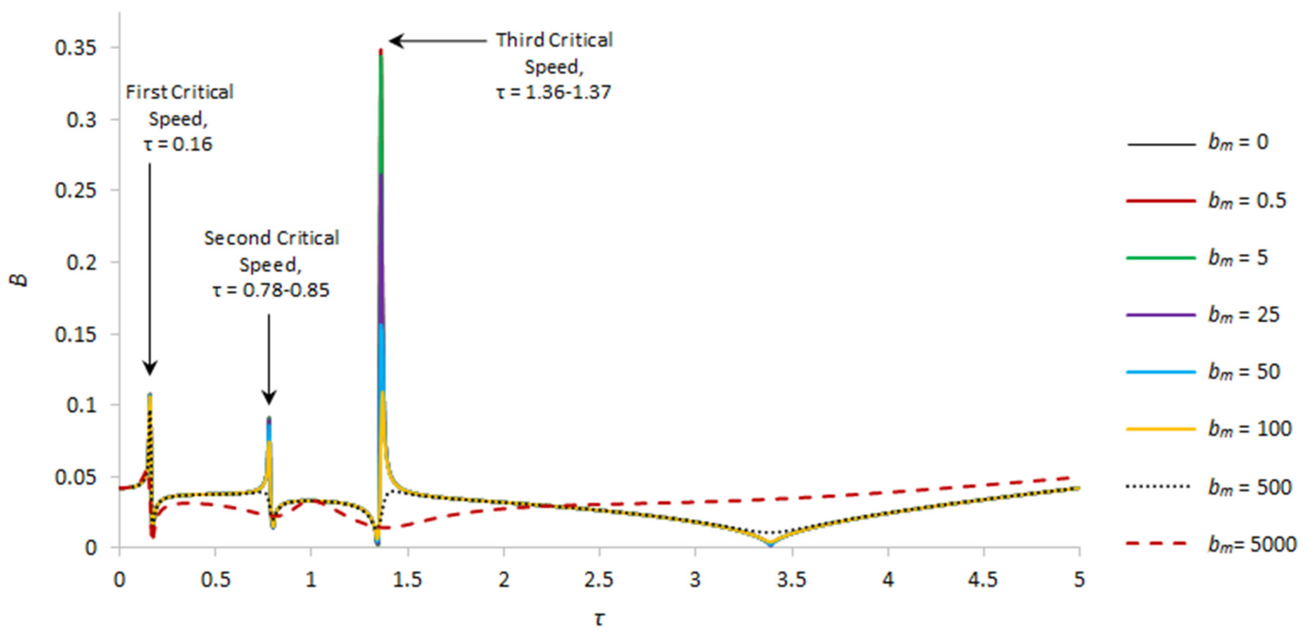
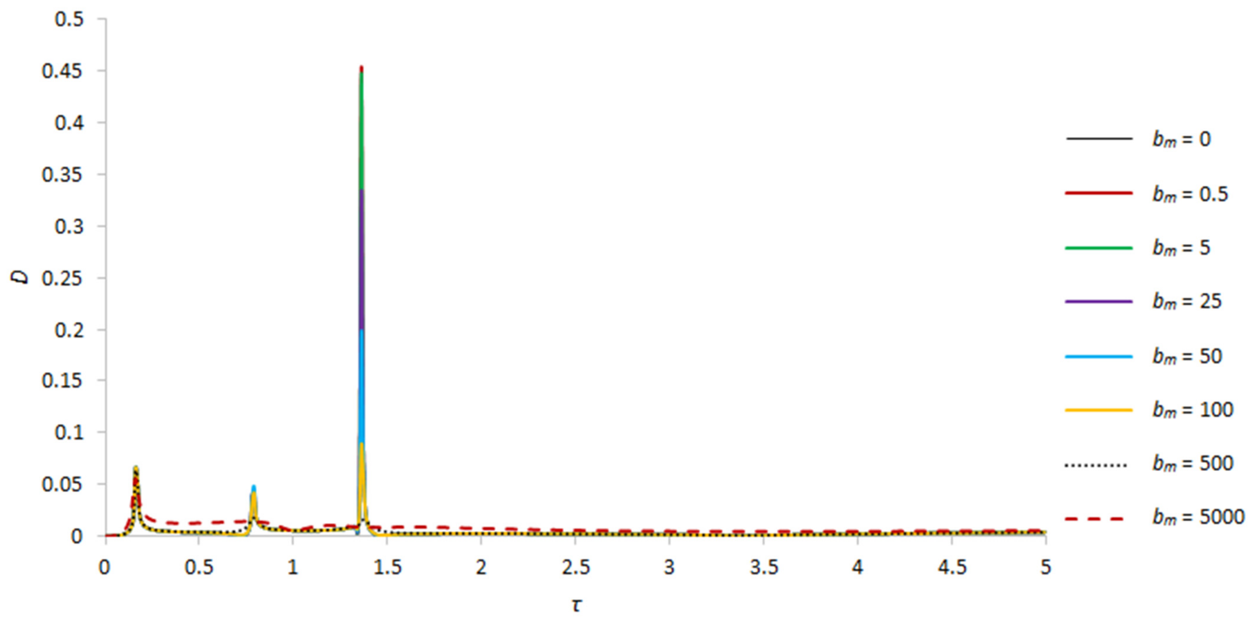
To evaluate the dependence of the damping and shift in frequencies of natural oscillations on the magnetic field, the operation of the rotor system with different values of parameters bm and γ at the maximum amplitudes of the rotor system, which are observed at the main resonance, i.e., at s = 1, was considered (see Figure 2, Figure 3, Figure 4, Figure 5, Figure 6, Figure 7, Figure 8, Figure 9, Figure 10 and Figure 11).
In the general case, three critical frequencies are observed in the system (see Figure 2 and Figure 3). This means that due to the presence of liquid even in a small amount in the rotor cavity, two additional critical frequencies are superimposed with amplitudes, the values of which increase until the cavity is filled by one third [20]. A further increase in the amount of liquid in the cavity leads to the complete suppression of the second critical frequency, thus, at γ = 1 (complete filling of the cavity with liquid), two critical frequencies will be observed in the system.
An increase in the value of the parameter that characterizes the effect of a magnetic field on a liquid particle, in general, positively affects the dynamics of the system. When varying the bm parameter, a significant influence is observed for the amplitudes at the third critical frequency [21]. With an increase in bm, the amplitudes of the second critical frequency are damped more weakly, and the amplitudes of the first critical frequency practically do not change, as they are also present in the absence of liquid in the rotor cavity. It should be noted that at a sufficiently high magnetic field strength, i.e., at bm = 5000, the oscillations of the system are practically similar to the case of an empty rotor, as the liquid in this case, as if “solidifies” and behaves like a solid body [22]. No shift in critical frequencies is observed in all cases, except for bm = 5000. For clarity and convenience of application of the results in engineering practice, the authors plotted the dependencies of critical amplitudes for different values of the parameters bm and γ (see Figure 2 and Figure 3).
With a small amount of liquid in the rotor cavity, for example, at γ = 13.8 (r0 = 0.93R), three critical frequencies are observed at τ = 0.16, τ = 0.78, and τ = 1.36, and three zones of self-oscillations, the maximum amplitudes of the rotor and foundation are observed at the third critical speed in cases bm = 0.100. Due to the small amount of liquid, the second critical frequency has smaller amplitudes compared to the first. With an increase in the bm parameter to 500, a slight shift in the second and third critical frequencies is observed towards an increase in the angular velocities of the rotor rotation [23,24]. In the case of a sufficiently high magnetic field strength, the second critical frequency shifts in the direction of increasing dimensionless frequency up to τ = 1, whereas the third critical frequency of the rotor and foundation is completely damped. The numerical values of the amplitudes for this case are presented in Table 1. Dashes in the table indicate the absence of critical frequencies or the complete damping of the natural oscillation amplitudes in this interval [25].
Table 1. Critical Speeds.
B, γ = 13.8First Critical Speed
Amplitude Value
Second Critical Speed
Amplitude Value
Third Critical Speed
Amplitude Value
bm = 00.1068045741, τ = 0.160.090720226, τ = 0.780.345717672, τ = 1.36
bm = 0.50.106796702, τ = 0.160.090718, τ = 0.780.345709, τ = 1.36
bm = 50.106725474, τ = 0.160.09065, τ = 0.780.341007, τ = 1.36
bm = 250.10640083, τ = 0.160.089259, τ = 0.780.256448, τ = 1.36
bm = 500.105976946, τ = 0.160.085366, τ = 0.780.155548, τ = 1.36
bm = 1000.105071989, τ = 0.160.073742909, τ = 0.780.109144682, τ = 1.36
bm = 5000.095853985, τ = 0.160.039189072, τ = 0.790.03976382, τ = 1.43
bm = 50000.054819732, τ = 0.150.032983197, τ = 1
D, γ = 13.8First Critical Speed
Amplitude Value
Second Critical Speed
Amplitude Value
Third Critical Speed
Amplitude Value
bm = 00.066385927, τ = 0.160.040110122, τ = 0.780.453737506, τ = 1.36
bm = 0.50.066382727, τ = 0.160.040109872, τ = 0.780.45372321, τ = 1.36
bm = 50.066353881, τ = 0.160.040087202, τ = 0.780.447400839, τ = 1.36
bm = 250.066224805, τ = 0.160.045069061, τ = 0.790.334005995, τ = 1.36
bm = 500.066061617, τ = 0.160.048328381, τ = 0.790.198268343, τ = 1.36
bm = 1000.065730061, τ = 0.160.041947113, τ = 0.790.088761642, τ = 1.36
bm = 5000.063037959, τ = 0.160.01798351, τ = 0.790.016219871, τ = 1.37
bm = 50000.054819732, τ = 0.160.014450226, τ = 0.85
Figure 2. Amplitude–frequency characteristics of natural oscillations of the rotor for s = 1 and γ = 13.8.
Applsci 13 12089 g002
Figure 3. Amplitude–frequency characteristics of natural oscillations of the foundation for s = 1 and γ = 13.8.
Applsci 13 12089 g003
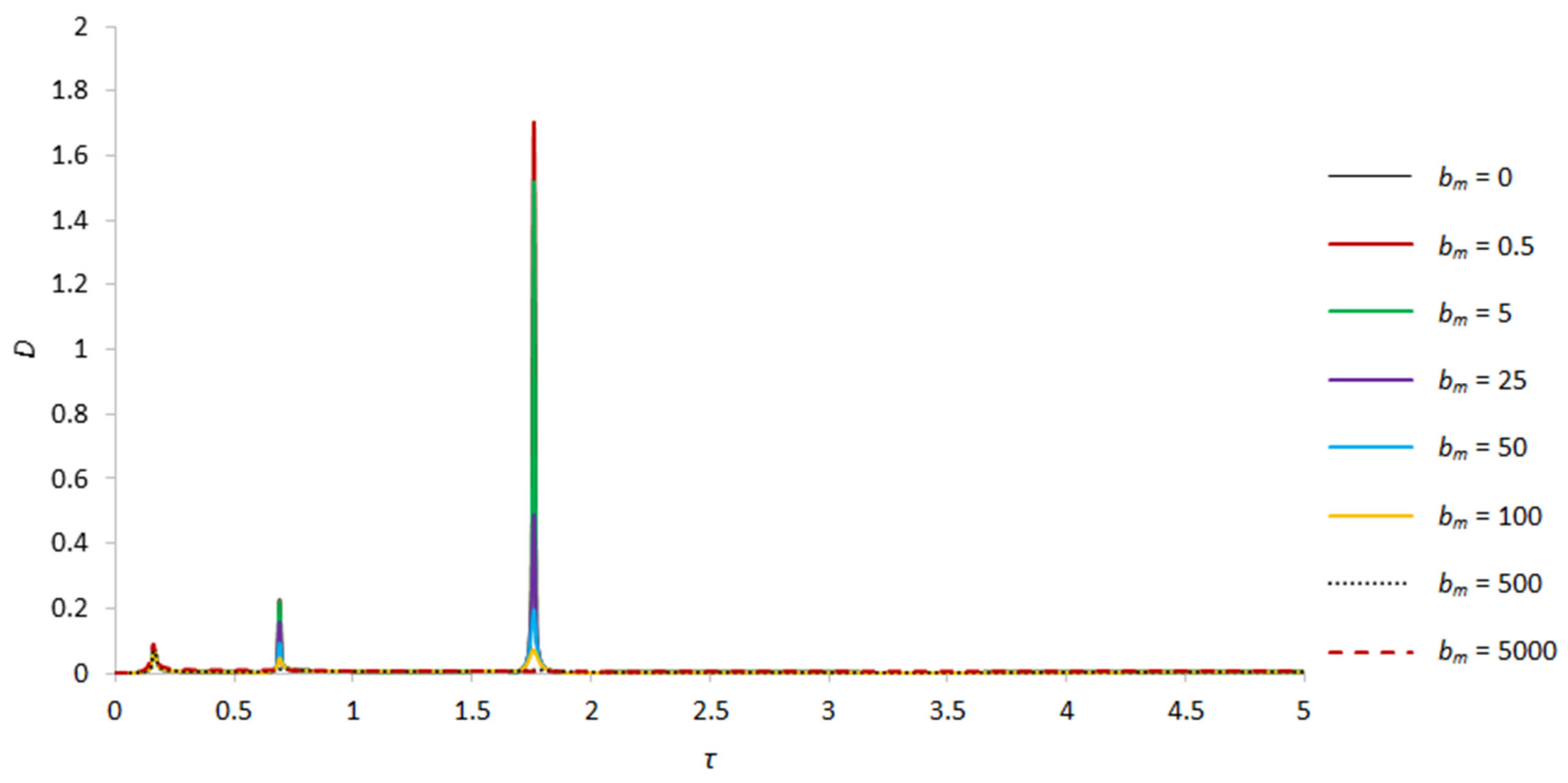
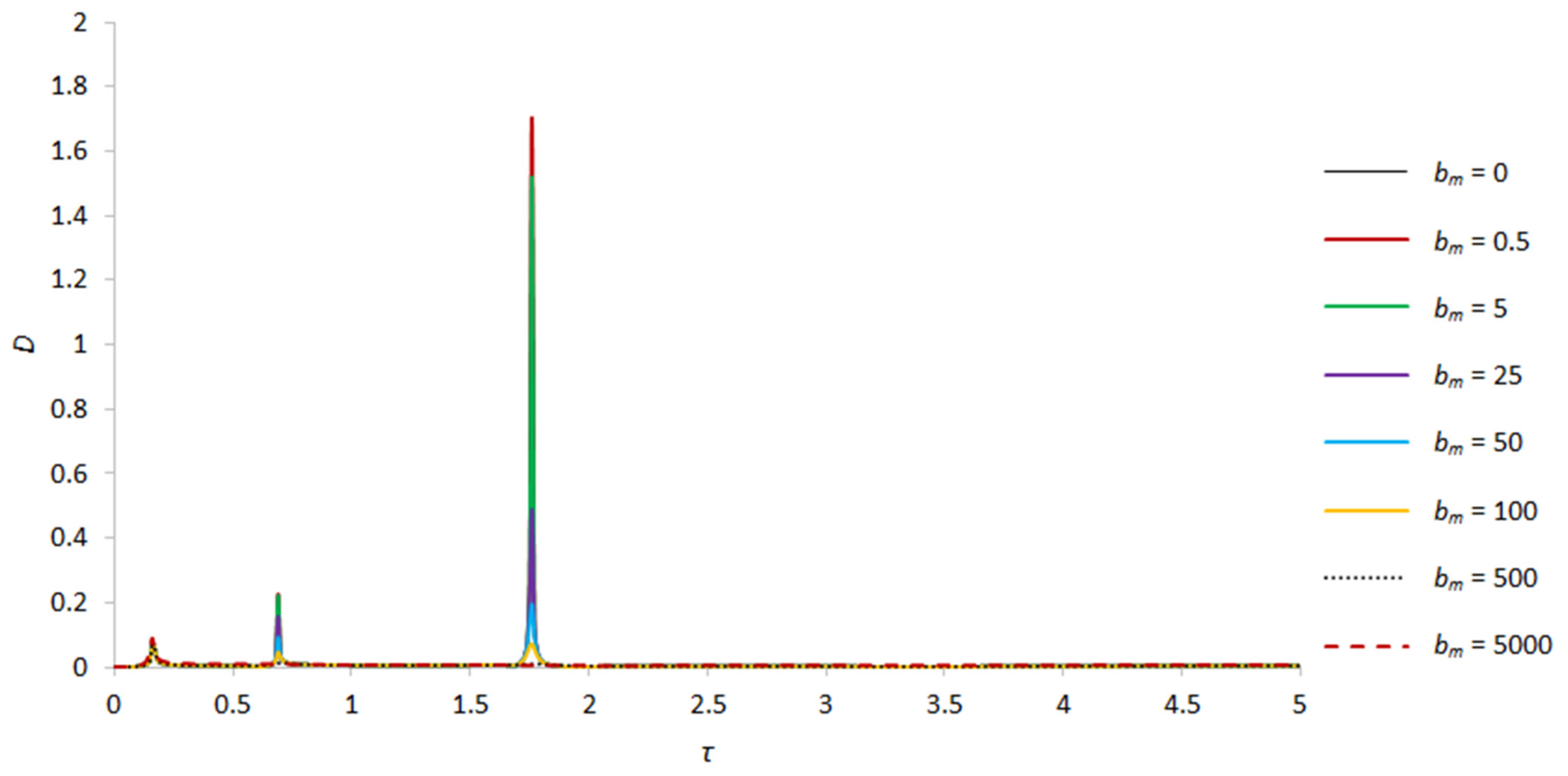
As the extent of filling increases, as mentioned above, the amplitudes of the second and third critical frequencies increase (see Figure 4 and Figure 5). For example, at γ = 4.56 (r0 = 0.8R) and bm = 0, the maximum values of the rotor amplitudes at the second and third critical frequencies are 3.3-fold and 5.4-fold greater than the values for the same case at γ = 13.8, and are 2.64-fold and 17.45-fold greater than the amplitudes at the first critical frequency, i.e., at τ = 0.16. Moreover, an increase in the amount of liquid in the rotor cavity affects the displacement of the second and third critical frequencies [26]. For example, in this case, the second critical frequency occurs a little earlier, compared with the case of γ = 13.8, at τ = 0.69, whereas the third critical frequency appears a little later, at τ = 1.76. With an increase in the parameter bm, for example, at bm = 500 and bm =5000, the oscillation amplitudes at the second and third critical speeds of the rotor and foundation, as expected, are damped up to their complete damping [27], which also indicates a positive effect of the high-frequency magnetic field on the system. The numerical values of the amplitudes for this case are presented in Table 2.
Table 2. Critical Speeds.
B, γ = 4.56First Critical Speed
Amplitude Value
Second Critical Speed
Amplitude Value
Third Critical Speed
Amplitude Value
bm = 00.110805396, τ = 0.160.292896271, τ = 0.691.917205238, τ = 1.76
bm = 0.50.110797785, τ = 0.160.292762234, τ = 0.691.915895568, τ = 1.76
bm = 50.110729214, τ = 0.160.286890823, τ = 0.691.710435466, τ = 1.76
bm = 250.110422857, τ = 0.160.205546804, τ = 0.690.558152699, τ = 1.76
bm = 500.110036396, τ = 0.160.124228936, τ = 0.690.231023687, τ = 1.76
bm = 1000.10925273, τ = 0.160.066849372, τ = 0.690.104944945, τ = 1.76
bm = 5000.102684806, τ = 0.16
bm = 50000.08448214, τ = 0.15
D, γ = 4.56First Critical Speed
Amplitude Value
Second Critical Speed
Amplitude Value
Third Critical Speed
Amplitude Value
bm = 00.07047227, τ = 0.160.226388549, τ = 0.691.704994351, τ = 1.76
bm = 0.50.070468917, τ = 0.160.226287308, τ = 0.691.70381006, τ = 1.76
bm = 50.07043893, τ = 0.160.221699183, τ = 0.691.520112352, τ = 1.76
bm = 250.070309814, τ = 0.160.157597686, τ = 0.690.488944743, τ = 1.76
bm = 500.070157935, τ = 0.160.034896767, τ = 0.70.194103909, τ = 1.76
bm = 1000.069885617, τ = 0.160.045941501, τ = 0.690.072065559, τ = 1.76
bm = 5000.069093807, τ = 0.160.012824952, τ = 0.70.010085603, τ = 1.77
bm = 50000.089252733, τ = 0.16
Figure 4. Amplitude–frequency characteristics of natural oscillations of the rotor for γ = 4.56, s = 1.
Applsci 13 12089 g004
Figure 5. Amplitude–frequency characteristics of natural oscillations of the foundation for γ = 4.56, s = 1.
Applsci 13 12089 g005
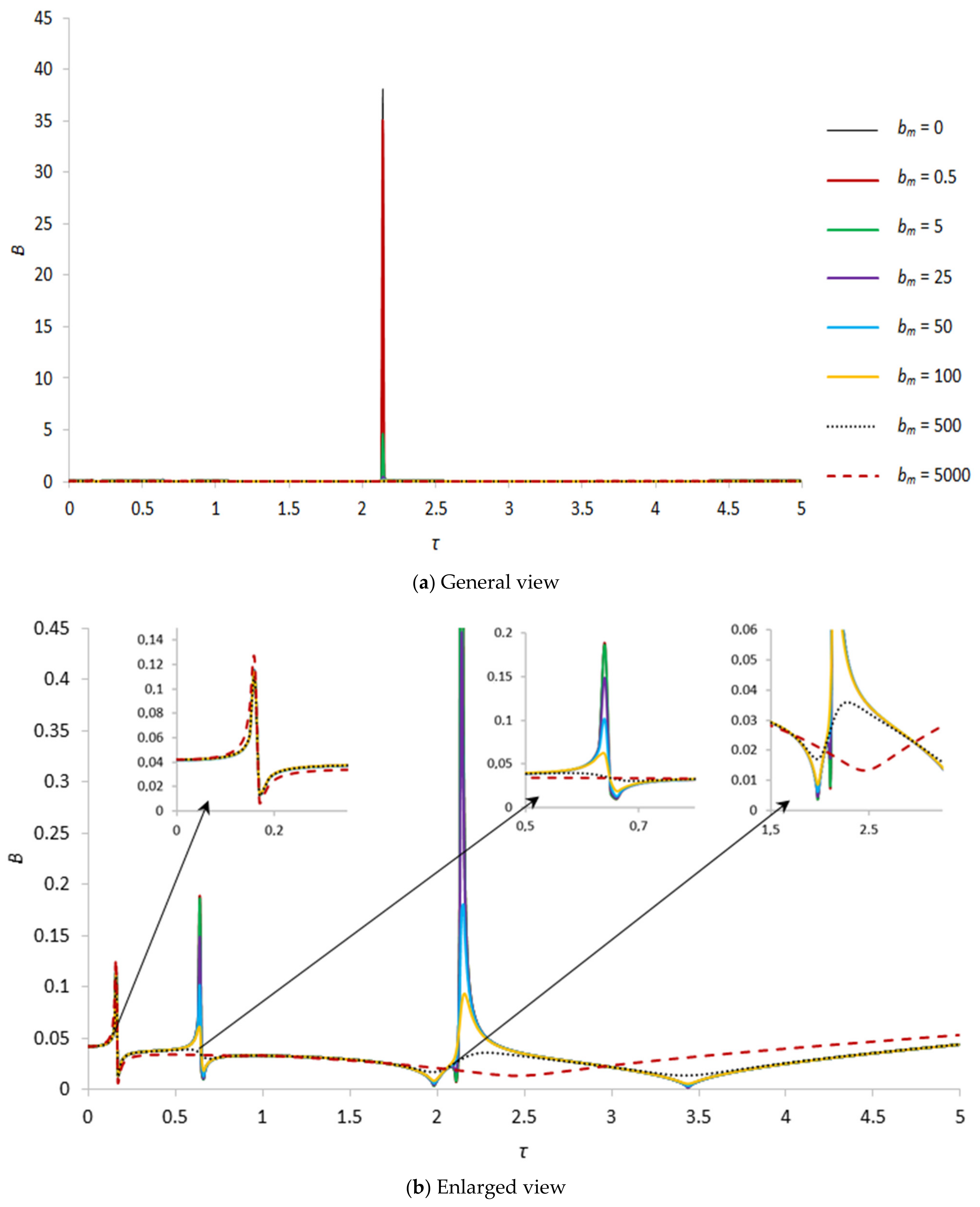
When the rotor cavity is filled with liquid by one third, i.e., at γ = 2.6, the system still has three critical frequencies (τ = 0.16, τ = 0.64 and τ = 2.14, see Figure 6 and Figure 7). In this case, the maximum values of the rotor amplitudes at the third critical frequency are 19.8-fold greater than the amplitudes in the similar case at γ = 4.56 (bm = 0), whereas the amplitudes of the second critical frequency are comparable with the previous case. An increase in the parameter that determines the influence of the magnetic field on a fluid particle from 0 to 0.5 leads to damping of the rotor and foundation amplitudes corresponding to the third critical frequency [28]. A significant decrease in the amplitudes of the second critical frequency occurs with an increase in bm to 25. Further, as bm increases to 500, the amplitudes of the second and third critical frequencies are almost completely suppressed. A change in the parameter that determines the influence of the magnetic field on a liquid particle has practically no effect on the amplitudes of the first critical frequency, except for large values of the magnetic field strength. It should be noted that in this case the third critical frequency shifts quite strongly to the right, in the direction of increasing natural frequencies, from 1.76 to 2.14, which also imposes certain restrictions on the choice of operating speed range in the absence of magnetic field influence [29]. The numerical values of the amplitudes for this case are presented in Table 3.
Table 3. Critical Speeds.
B, γ = 2.6First Critical Speed
Amplitude Value
Second Critical Speed
Amplitude Value
Third Critical Speed
Amplitude Value
bm = 0 0.188180917, τ = 0.6438.0983794, τ = 2.14
bm = 0.5 0.188128512, τ = 0.6435.05368501, τ = 2.14
bm = 50.114550189, τ = 0.160.185743424, τ = 0.644.620198303, τ = 2.14
bm = 250.114543039, τ = 0.160.148131171, τ = 0.640.442357104, τ = 2.14
bm = 500.113852547, τ = 0.160.100918717, τ = 0.640.180448011, τ = 2.15
bm = 1000.113189756, τ = 0.160.06088884, τ = 0.640.093096022, τ = 2.16
bm = 5000.109089699, τ = 0.16
bm = 50000.124710542, τ = 0.16
D, γ = 2.6First Critical Speed
Amplitude Value
Second Critical Speed
Amplitude Value
Third Critical Speed
Amplitude Value
bm = 00.074299992, τ = 0.160.130906778, τ = 0.6437.42981166, τ = 2.14
bm = 0.50.074296638, τ = 0.160.130872119, τ = 0.6434.43775859, τ = 2.14
bm = 50.074266809, τ = 0.160.129169584, τ = 0.644.531230535, τ = 2.14
bm = 250.074142119, τ = 0.160.101854993, τ = 0.640.417323892, τ = 2.14
bm = 500.074004213, τ = 0.160.067028512, τ = 0.640.148186179, τ = 2.14
bm = 1000.073787317, τ = 0.160.036021818, τ = 0.640.053425977, τ = 2.14
bm = 5000.074595252, τ = 0.160.01092513, τ = 0.660.007393946, τ = 2.14
bm = 50000.140446071, τ = 0.16
Figure 6. Amplitude–frequency characteristic of natural oscillations of the rotor for s = 1 and γ = 2.6; (a) general view; (b) enlarged view.
Applsci 13 12089 g006
Figure 7. Amplitude–frequency characteristic of natural oscillations of the foundation for s = 1 and γ = 2.6; (a) general view; (b) enlarged view.
Applsci 13 12089 g007
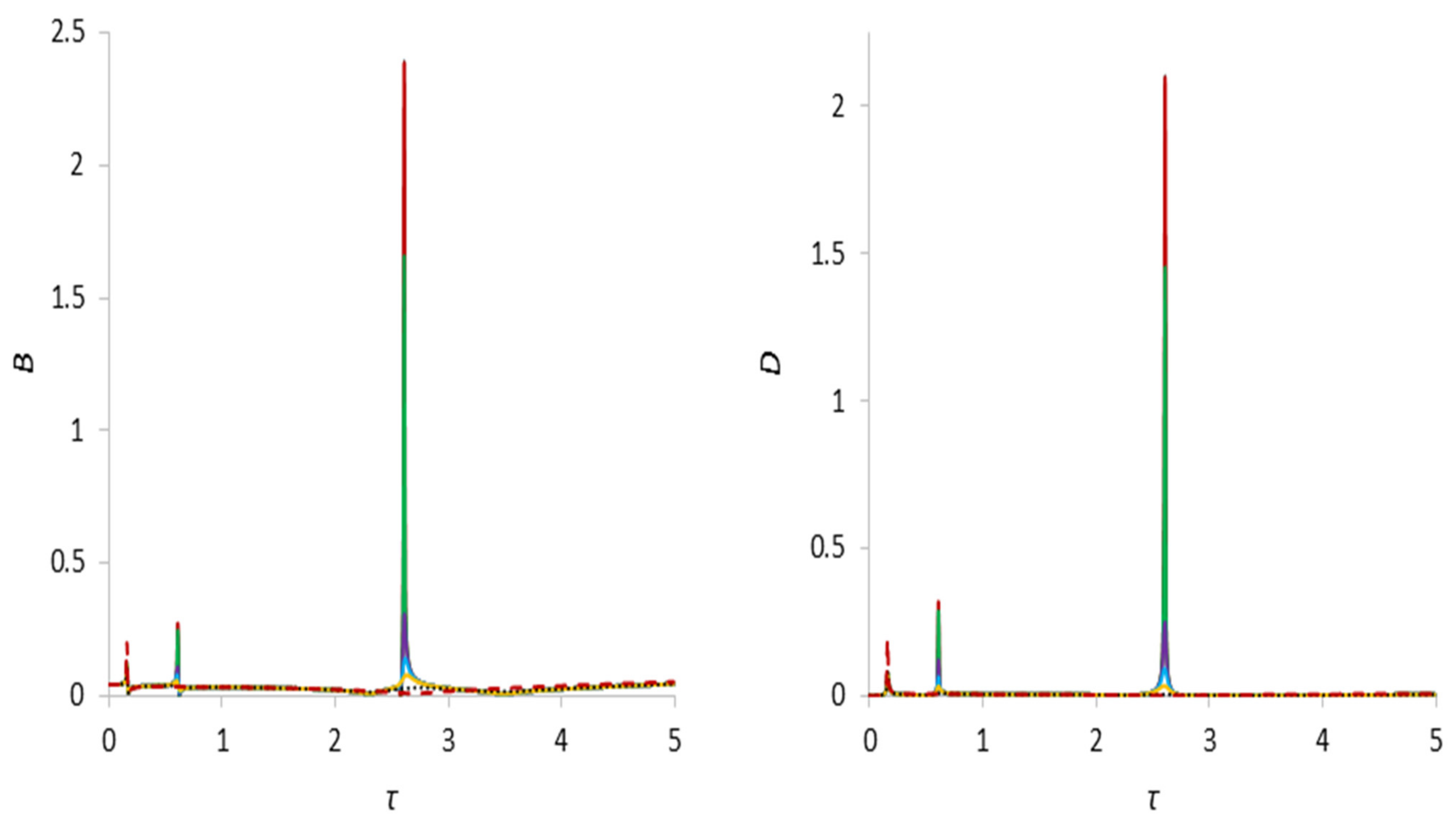
When the rotor cavity is half and two-thirds full, i.e., at γ = 1.67 and γ = 1.25, the character of changes in the amplitude and frequency of natural oscillations of the system is similar to the case when the rotor cavity is one-third filled. In this case, the system oscillates with smaller amplitudes by almost an order of magnitude lower than when the rotor cavity is one-third full (see Figure 8 and Figure 9). In the case of half filling, the second and third critical frequencies are still greater than the first critical frequency [51]. Accordingly, a stronger shift in critical frequencies is observed compared to those listed above, for example, the second critical frequency appears already at τ = 0.61, while the third already at τ = 2.61.
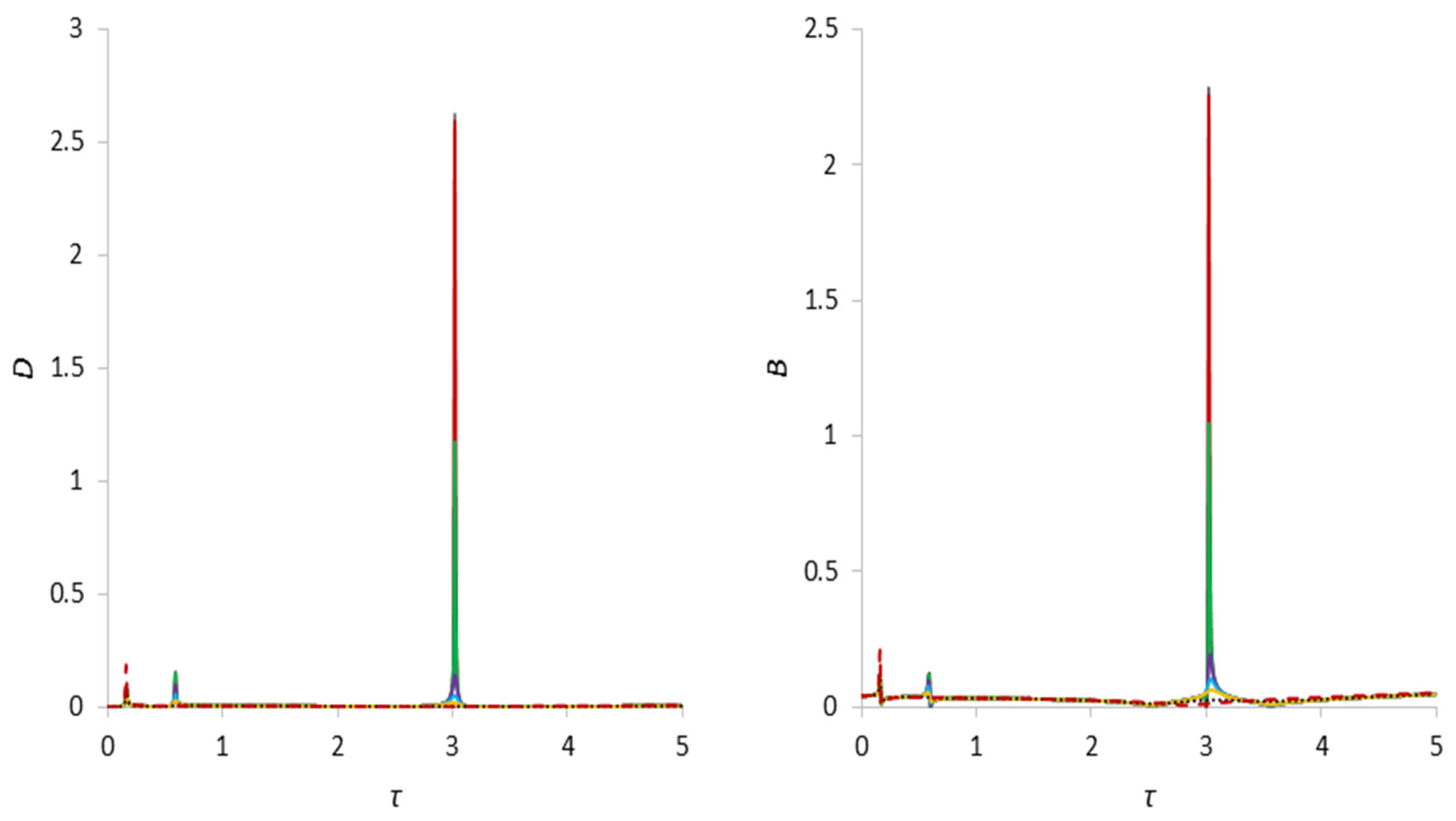
When the cavity is filled by two-thirds, the amplitudes of the first and second critical frequencies are commensurate with each other and with the above case. The second critical frequency shifts in the direction of decreasing angular velocities and appears at τ = 0.59, whereas the third critical frequency shifts to the left in the direction of its increase and appears at τ = 3.02. With an increase in the parameter bm, the oscillation amplitudes at the second and third critical speeds of the rotor and foundation, as before, are damped until their full damping. The numerical values of the amplitudes for this case are presented in Table 4 and Table 5.
Table 4. Critical Speeds.
B, γ = 1.67First Critical Speed
Amplitude Value
Second Critical Speed
Amplitude Value
Third Critical Speed
Amplitude Value
bm = 00.118574461, τ = 0.160.27197385, τ = 0.612.395991343, τ = 2.61
bm = 0.50.11856806, τ = 0.160.271326026, τ = 0.612.386092738, τ = 2.61
bm = 50.118510785, τ = 0.160.244571454, τ = 0.611.657566825, τ = 2.61
bm = 250.118263621, τ = 0.160.108761599, τ = 0.610.307975554, τ = 2.61
bm = 500.117971542, τ = 0.160.079987206, τ = 0.610.141437807, τ = 2.61
bm = 1000.117443017, τ = 0.160.058212949, τ = 0.60.078056973, τ = 2.61
bm = 5000.115713077, τ = 0.16
bm = 50000.200140464, τ = 0.16
D, γ = 1.67First Critical Speed
Amplitude Value
Second Critical Speed
Amplitude Value
Third Critical Speed
Amplitude Value
bm = 00.078416443, τ = 0.160.319661082, τ = 0.612.101480075, τ = 2.61
bm = 0.50.078413261, τ = 0.160.318899815, τ = 0.612.092707266, τ = 2.61
bm = 50.078385116, τ = 0.160.286969287, τ = 0.611.448573522, τ = 2.61
bm = 250.078270549, τ = 0.160.122332756, τ = 0.610.248941102, τ = 2.61
bm = 500.078151336, τ = 0.160.064906783, τ = 0.610.091711735, τ = 2.61
bm = 1000.077991713, τ = 0.160.03343016, τ = 0.60.034567932, τ = 2.61
bm = 5000.080131667, τ = 0.16
bm = 50000.193818388, τ = 0.16
Table 5. Critical Speeds.
B, γ = 1.25First Critical Speed
Amplitude Value
Second Critical Speed
Amplitude Value
Third Critical Speed
Amplitude Value
bm = 00.121638282, τ = 0.160.122951082, τ = 0.592.281429046, τ = 3.02
bm = 0.50.121632639, τ = 0.160.122901957, τ = 0.592.25145796, τ = 3.02
bm = 50.121582276, τ = 0.160.121641647, τ = 0.591.035804071, τ = 3.02
bm = 250.121367604, τ = 0.160.098499341, τ = 0.580.166361948, τ = 3.02
bm = 500.121120227, τ = 0.160.078839058, τ = 0.580.103151902, τ = 3.02
bm = 1000.120694759, τ = 0.160.055532351, τ = 0.580.06308127, τ = 3.02
bm = 5000.120406103, τ = 0.16
bm = 50000.210144507, τ = 0.16
D, γ = 1.25First Critical Speed
Amplitude Value
Second Critical Speed
Amplitude Value
Third Critical Speed
Amplitude Value
bm = 00.081552542, τ = 0.160.154403646, τ = 0.592.6271788, τ = 3.02
bm = 0.50.081549629, τ = 0.160.154341266, τ = 0.592.59220114, τ = 3.02
bm = 50.081523936, τ = 0.160.152395469, τ = 0.591.173065248, τ = 3.02
bm = 250.081421162, τ = 0.160.098951316, τ = 0.580.14148849, τ = 3.02
bm = 500.081318754, τ = 0.160.03067025, τ = 0.590.051515196, τ = 3.02
bm = 1000.081199692, τ = 0.160.055532351, τ = 0.590.020073614, τ = 3.02
bm = 5000.083967196, τ = 0.16
bm = 50000.186578729, τ = 0.16
Figure 8. Amplitude–frequency characteristic of natural oscillations of the rotor and foundation for s = 1 and γ = 1.67.
Applsci 13 12089 g008
Figure 9. Amplitude–frequency characteristic of natural oscillations of the rotor and foundation for s = 1 and γ = 1.25.
Applsci 13 12089 g009
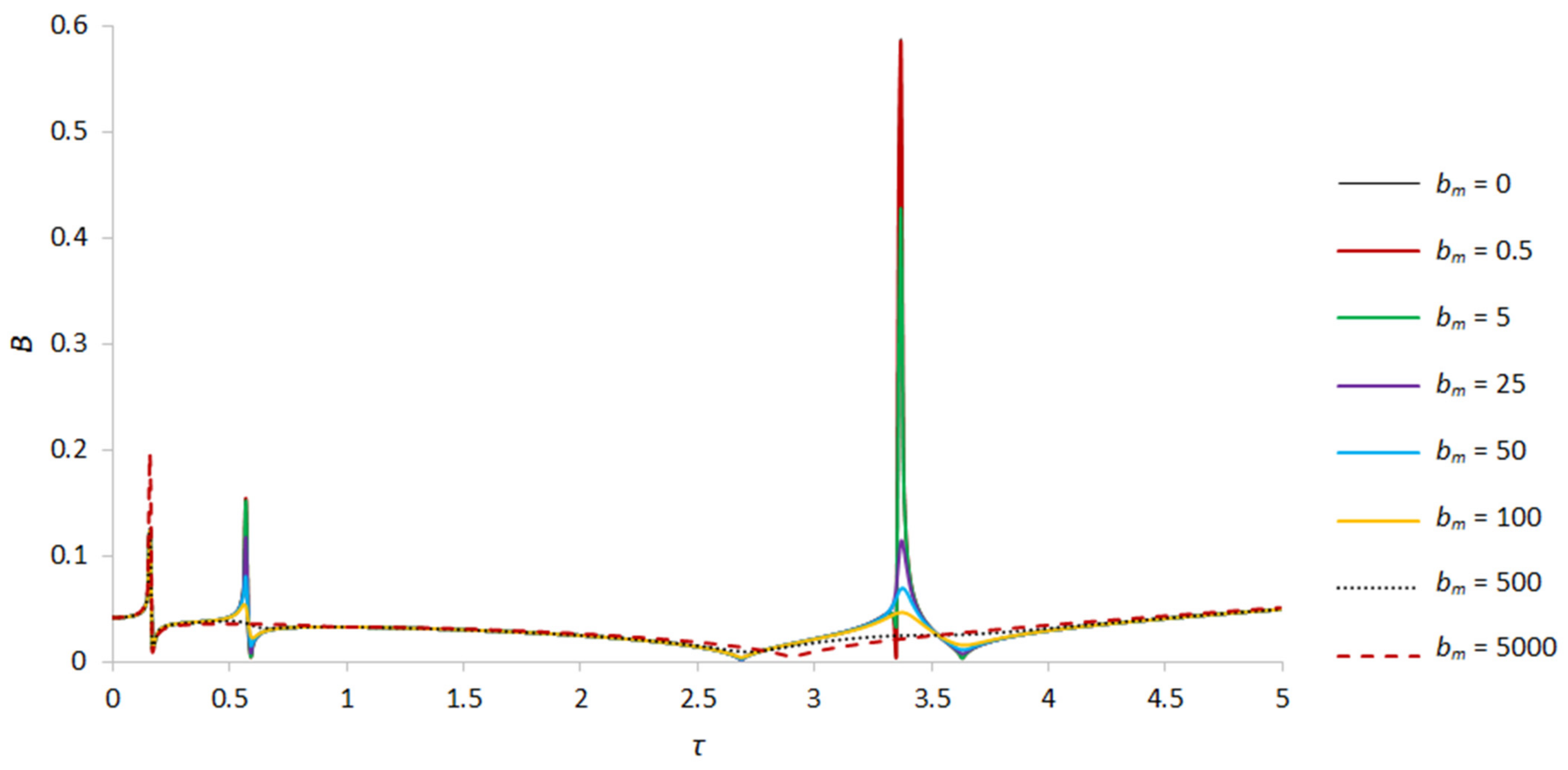
When the rotor cavity is almost completely filled with liquid, for example, at γ = 1.03 (r0 = 0.125R), the amplitudes at the second critical frequency are smaller than the amplitudes at the first critical frequency, whereas the amplitudes at the third critical frequency are several-fold smaller than the values observed in the case when the cavity is filled with liquid by half and by two thirds (see Figure 10 and Figure 11). The shift in critical frequencies due to an increase in the amount of liquid in the cavity in this case is even more pronounced. For example, the second critical frequency in this case appears already at τ = 0.57 and the third already at τ = 3.36. This means that with an increase in filling, the second critical frequency shifts to the first critical frequency until it merges with it, whereas the third critical frequency shifts in the direction of increasing frequency to the right and is almost completely damped with an increase in the amount of fluid in the rotor cavity. As before, with an increase in the parameter characterizing the influence of the magnetic field on a liquid particle bm, the amplitudes of the second and third critical frequencies are damped up to their complete dampening. The numerical values of the amplitudes for this case are presented in Table 6.
Table 6. Critical Speeds.
B, γ = 1.03First Critical Speed
Amplitude Value
Second Critical Speed
Amplitude Value
Third Critical Speed
Amplitude Value
bm = 00.123836133, τ = 0.160.154082698, τ = 0.570.582653298, τ = 3.37
bm = 0.50.123831142, τ = 0.160.15403417, τ = 0.570.580389919, τ = 3.37
bm = 50.123786664, τ = 0.160.151690752, τ = 0.570.425847453, τ = 3.37
bm = 250.123598669, τ = 0.160.117230408, τ = 0.570.114353556, τ = 3.37
bm = 500.123385864, τ = 0.160.080130589, τ = 0.570.069492128, τ = 3.38
bm = 1000.123033788, τ = 0.160.054080999, τ = 0.560.046679793, τ = 3.37
bm = 5000.123518243, τ = 0.16
bm = 50000.196425395, τ = 0.16
D, γ = 1.03First Critical Speed
Amplitude Value
Second Critical Speed
Amplitude Value
Third Critical Speed
Amplitude Value
bm = 00.083803356, τ = 0.160.101565041, τ = 0.570.124078552, τ = 3.35
bm = 0.50.083800714, τ = 0.160.101535013, τ = 0.570.123990942, τ = 3.35
bm = 50.08377746, τ = 0.160.099920685, τ = 0.570.115971317, τ = 3.35
bm = 250.083685484, τ = 0.160.075582465, τ = 0.570.050630183, τ = 3.35
bm = 500.08359651, τ = 0.160.048524802, τ = 0.570.022746045, τ = 3.35
bm = 1000.083504258, τ = 0.160.028624914, τ = 0.580.010481636, τ = 3.33
bm = 5000.08647026, τ = 0.160.009075681, τ = 0.62
bm = 50000.165670988, τ = 0.16
Figure 10. Amplitude–frequency characteristic of natural oscillations of the rotor for s = 1 and γ = 1.03.
Applsci 13 12089 g010
Figure 11. Amplitude–frequency characteristic of natural oscillations of the foundation for s = 1 and γ = 1.03.
Applsci 13 12089 g011
The electrical conductivity of the liquid is directly proportional to the length of the liquid volume in the rotor cavity and inversely proportional to the cross-sectional area of this volume and its electrical resistance. The intensity of a uniform axial magnetic field is proportional to the current strength, length and number of turns of the solenoid. Thus, due to sufficient damping of the amplitudes of the second and third critical frequencies, as well as due to its simpler implementation from the technical point of view, for further studying of the effect of a high-frequency magnetic field on nonlinear oscillations it was decided to use the value of the parameter bm = 100. The shift in critical frequencies depends not only on the amount of liquid being filled but also on the frequency of the disturbing force, in our case, on the angular velocity of the rotor. To assess the shift in critical frequencies, diagrams were constructed where the abscissa axes correspond to the dimensionless angular velocity of rotation of the rotor s and the ordinate axes to the dimensionless natural frequency τ.

6. Conclusions

The analysis of sources in this field of research shows that this work is the first where an analytically generalized dynamic model of the “rotor–weakly conductive fluid–foundation” system, which takes into account the electromagnetic properties of a viscous fluid and its vibrations, the nonlinear stiffness properties of bearing supports and vibrations of the foundation, was developed and solved. Due to the presence of liquid in the rotor cavity, several additional critical frequencies are imposed on the system, whose amplitudes in some cases exceed the amplitudes of the empty rotor by several orders of magnitude, which also imposes certain restrictions on the choice of operating speeds. An increase in the value of the parameter that characterizes the influence of the magnetic field on a fluid particle leads to damping of the amplitudes of the natural oscillations of the rotor and the foundation, which generally has a positive effect on the dynamics of the system. In this case, a change in the value of the magnetic field strength has practically no effect on the shifts in critical frequencies. In case of synchronous precession, the fluid is motionless with respect to the rotor cavity. There is no wave motion of the liquid. The motion caused by the rotor unbalance is similar to the case when the cavity is completely filled with liquid.

Author Contributions

Conceptualization, A.K.; methodology, A.K.; software, G.-G.A.I.; validation, A.Z. and A.K.; formal analysis, A.K. and A.Z.; investigation, A.K. and A.Z.; resources, A.K. and A.Z.; data curation, G.-G.A.I., A.Z. and A.K.; writing—original draft preparation, A.K.; writing—review and editing, A.Z.; visualization, G.-G.A.I.; supervision, A.Z.; project administration, A.K.; funding acquisition, A.K. All authors have read and agreed to the published version of the manuscript.

Funding

This research was funded by Al-Farabi Kazakh National University, grant number AP19677384.

Institutional Review Board Statement

This study did not require ethical approval.

Informed Consent Statement

Not applicable.

Data Availability Statement

Data are contained within the article.

Acknowledgments

This work has been supported financially by the research project (AP19677384—Development and research of the dynamics of a gas centrifuge on magnetic bearings with nonlinear characteristics and a control system) of the Ministry of Science and Higher Education of the Republic of Kazakhstan and was performed at the Research Institute of Mathematics and Mechanics in Al-Farabi Kazakh National University, which is gratefully acknowledged by the authors.

Conflicts of Interest

The authors confirm that they have no conflict of interest with respect to the work described in this manuscript.

References

  1. Kydyrbekuly, A.; Zhauyt, A.; Ibrayev, G.-G.A. Investigation of Nonlinear Forced Vibrations of the “Rotor-Movable Foundation” System on Rolling Bearings by the Jacobi Elliptic Functions Method. Appl. Sci. 2022, 12, 7042. [Google Scholar] [CrossRef]
  2. Kydyrbekuly, A.; Ibrayev, G.G.A.; Ospan, T.; Nikonov, A. Multi-parametric Dynamic Analysis of a Rolling Bearings System. Strojniski Vestnik. J. Mech. Eng. 2021, 67, 421–432. [Google Scholar] [CrossRef]
  3. Feng, N.; Hahn, E. Experimental identification of the foundation in a rotor-bearing-foundation system. In Proceedings of the 5th IFToMM International Conference on Rotor Dynamics, Darmstadt, Germany, 7–10 September 1998; pp. 734–745. [Google Scholar]
  4. Saito, Y.; Sawada, T. Liquid sloshing in a rotating, laterally oscillating cylindrical container. Univers. J. Mech. Eng. 2017, 5, 97–101. [Google Scholar] [CrossRef]
  5. Eswaran, M.; Saha, U.K. Sloshing of Liquids in Partially Filled Tanks-A Review of Experimental Investigations. Ocean. Syst. Eng. 2011, 1, 131–155. [Google Scholar] [CrossRef]
  6. Tchomeni, B.X.; Alugongo, A. Modelling and numerical simulation of vibrations induced by mixed faults of a rotor system immersed in an incompressible viscous fluid. Adv. Mech. Eng. 2018, 10, 1–21. [Google Scholar] [CrossRef]
  7. Behera, R.K.; Parhi, D.R.; Sahu, S.K. Vibration analysis of a cracked rotor surrounded by viscous liquid. J. Vib. Control 2006, 12, 465–494. [Google Scholar] [CrossRef]
  8. Tarapov, I.E. On the basic equations and problems of the hydrodynamics of polarizable and magnetizable media. Theory Funct. Funct. Anal. Their Appl. 1973, 15, 221–239. [Google Scholar]
  9. Shimogo, T.; Kazao, Y. Critical speed of rotor in a liquid. Bull. JSME 1982, 25, 277–283. [Google Scholar] [CrossRef]
  10. Kydyrbekuly, A.; Khajiyeva, L.; Gulama-Garyp, A.Y. Nonlinear vibrations of a rotor-fluid-foundation system supported by rolling bearings. Stroj. Vestn./J. Mech. Eng. 2016, 62, 351–362. [Google Scholar] [CrossRef]
  11. Al-Bedoor, B.O. Transient torsional and lateral vibrations of unbalanced rotors with rotor-to-stator rubbing. J. Sound Vib. 2000, 229, 627–645. [Google Scholar] [CrossRef]
  12. Tchomeni, B.X.; Alugongo, A.A.; Masu, L.M. A fault analysis cracked-rotor-to-stator rub and unbalance by vibration analysis technique. Int. J. Mech. Aerospace Ind. Mechatr. Manuf. Eng. 2015, 9, 1883–1892. [Google Scholar]
  13. Stewartson, K. On the stability of a spinning top containing liquid. J. Fluid Mech. 1959, 5, 577–592. [Google Scholar] [CrossRef]
  14. Bauer, H.F.; Eidel, W. Axisymmetric oscillations in a slowly rotating cylindrical container filled with viscous liquid. Eng. Res. 1997, 63, 215–223. [Google Scholar]
  15. Kimura, K.; Takahara, H.; Sakata, M. Effects of higher order radial modes upon nonlinear sloshing in a circular cylindrical tank subjected to vertical excitation. Trans. JSMEC 1994, 60, 3259–3267. [Google Scholar] [CrossRef]
  16. Bauer, H.F. Natural frequencies and response of spinning liquid column with apparently sliding contact line. Acta Mech. 1993, 97, 115–122. [Google Scholar] [CrossRef]
  17. Awrejcewicz, J.; Dzyubak, L.P. 2-DOF non-linear dynamics of a rotor suspended in the magneto-hydrodynamic field in the case of soft and rigid magnetic materials. Int. J. Non-Linear Mech. 2010, 45, 919–930. [Google Scholar] [CrossRef]
  18. Awrejcewicz, J.; Dzyubak, L.P. Chaos caused by hysteresis and saturation phenomenon in 2-DOF vibrations of the rotor supported by the magneto-hydrodynamic bearing. Int. J. Bifurc. Chaos 2011, 21, 2801–2823. [Google Scholar] [CrossRef]
  19. Ji, J.C.; Hansen, C.H. Non-linear oscillations of a rotor in active magnetic bearings. J. Sound Vib. 2001, 240, 599–612. [Google Scholar] [CrossRef]
  20. Ji, J.C.; Leung, A. Non-linear oscillations of a rotor-magnetic bearing system under superharmonic resonance conditions. Int. J. Non-Linear Mech. 2003, 38, 829–835. [Google Scholar] [CrossRef]
  21. Kamel, M.; Bauomy, H. Nonlinear oscillation of a rotor-AMB system with time varying stiffness and multi-external excitations. J. Vib. Acoust. 2009, 131, 031009. [Google Scholar] [CrossRef]
  22. Saeed, N.A.; Kamel, M. Nonlinear PD-controller to suppress the nonlinear oscillations of horizontally supported Jeffcott-rotor system. Int. J. Non-Linear Mech. 2016, 87, 109–124. [Google Scholar] [CrossRef]
  23. Galdi, G.P.; Mazzone, G.; Zunino, P. Inertial Motions of a Rigid Body with a Cavity Filled with a Viscous Fluid. Comptes Rendus Mec. 2013, 341, 760–765. [Google Scholar] [CrossRef]
  24. Kuang, J.L.; Leung, A.Y.T.; Tan, S. Chaotic Attitude Oscillations of a Satellite Filled with a Rotating Ellipsoidal Mass of Liquid Subject to Gravity-Gradient Torgues. Chaos 2004, 14, 111–117. [Google Scholar] [CrossRef] [PubMed]
  25. Leung, A.Y.T.; Kuang, J.L. Chaotic Rotations of a Liquid- Filled Solid. J. Sound Vib. 2007, 302, 540–563. [Google Scholar] [CrossRef]
  26. Baozeng, Y.; Xie, J. Chaotic Attitude Maneuvers in Spacecraft with Completety Liquid—Filled Cavity. J. Sound Vib. 2007, 302, 643–656. [Google Scholar] [CrossRef]
  27. Ishiyama, T.; Kaneko, S.; Takemoto, S.; Sawada, T. Relation Between Dynamic Pressure and Displacement of Free Surface in Two-Layer Sloshing Between a Magnetic Fluid and Silicone Oil. Mater. Sci. Forum. 2014, 792, 33–38. [Google Scholar] [CrossRef]
  28. Romero-Calvo, Á.; Cano Gómez, G.; Castro-Hernández, E.; Maggi, F. Free and forced oscillations of magnetic liquids under low-gravity conditions. J. Appl. Mech. 2020, 87, 021010. [Google Scholar] [CrossRef]
  29. Saeed, N.A.; El-Ganaini, W. Time-delayed control to suppress the nonlinear vibrations of a horizontally suspended Jeffcott-rotor system. Appl. Math. Model. 2017, 44, 523–539. [Google Scholar] [CrossRef]
  30. Sekhar, A.S.; Prabhu, B.S. Condition monitoring of cracked rotors through transient response. Mech. Mach. Theory 1998, 33, 1167–1175. [Google Scholar] [CrossRef]
  31. Derendyayev, N.V.; Soldatov, I.N.; Vostrukhov, A.V. Stability and Andronov-Hopf bifurcation of steady-state motion of rotor system partly filled with liquid: Continuous and discrete models. J. Appl. Mech. 2006, 73, 580–589. [Google Scholar] [CrossRef]
  32. Manasseh, R. Distortions of inertia waves in a rotating fluid cylinder forced near its fundamental mode resonance. J. Fluid Mech. 1994, 265, 345–370. [Google Scholar] [CrossRef]
  33. Zhu, C. Experimental investigation into the effect of fluid viscosity on instability of an overhung flexible rotor partially filled with fluid. J. Vib. Acoust. 2006, 128, 392–401. [Google Scholar]
  34. Urbiola-Soto, L.; Lopez-Parra, M. Liquid self-balancing device effects on flexible rotor stability. Shock Vib. 2013, 20, 109–121. [Google Scholar] [CrossRef]
  35. Harsha, S.P. Non-linear dynamic response of a balanced rotor supported on rolling element bearings. Mech. Syst. Signal Process. 2005, 19, 551–578. [Google Scholar] [CrossRef]
  36. Tiwari, M.; Gupta, K.; Prakash, O. Effect of radial internal clearance of a ball bearing on the dynamics of a balanced horizontal rotor. J. Sound Vib. 2000, 238, 723–756. [Google Scholar] [CrossRef]
  37. Tiwari, M.; Gupta, K.; Prakash, O. Dynamic response of an unbalanced rotor supported on ball bearings. J. Sound Vib. 2000, 238, 757–779. [Google Scholar] [CrossRef]
  38. Harsha, S.P. Nonlinear dynamic analysis of a highspeed rotor supported by rolling element bearings. J. Sound Vib. 2006, 290, 65–100. [Google Scholar] [CrossRef]
  39. Bai, C.; Zhang, H.; Xu, Q. Experimental and numerical studies on nonlinear dynamic behavior of rotor system supported by ball bearings. J. Eng. Gas Turbine Power. 2010, 132, 082502. [Google Scholar] [CrossRef]
  40. Harsha, S.P.; Sandeep, K.; Prakash, R. The effect of speed of balanced rotor on nonlinear vibrations associated with ball bearings. Int. J. Mech. Sci. 2003, 47, 225–240. [Google Scholar] [CrossRef]
  41. Savin, L.; Solomin, O.; Ustinov, D. Rotor dynamics on friction bearings with cryogenic lubrication. In Proceedings of the 10th World Congress on the Theory of Machine and Mechanisms, Oulu, Finland, 20–24 June 1999; Volume 4, pp. 1716–1721. [Google Scholar]
  42. Silin, R.; Royzman, V. The research into the automatic balancing process of rotors with vertical axis of rotation. In Proceedings of the 10th World Congress on the Theory of Machine and Mechanisms, Oulu, Finland, 20–24 June 1999; Volume 4, pp. 1734–1739. [Google Scholar]
  43. Ji, J.C.; Hansen, C.H.; Zander, A.C. Nonlinear dynamics of magnetic bearing systems. J. Intell. Mater. Syst. Struct. 2008, 19, 1471–1491. [Google Scholar] [CrossRef]
  44. Saeed, N.A.; Eissa, M.; El-Ganini, W.A. Nonlinear oscillations of rotor active magnetic bearings system. Nonlinear Dyn. 2013, 74, 1–20. [Google Scholar] [CrossRef]
  45. Du, T.C.; Geng, H.; Wang, B.; Lin, H.; Yu, L. Nonlinear oscillation of active magnetic bearing–rotor systems with a time-delayed proportional–derivative controller. Nonlinear Dyn. 2022, 109, 2499–2523. [Google Scholar] [CrossRef]
  46. Ji, J.C.; Yu, L.; Leung, A. Bifurcation behavior of a rotor supported by active magnetic bearings. J. Sound Vib. 2000, 235, 133–151. [Google Scholar] [CrossRef]
  47. Zhang, W.; Zhan, X.P. Periodic and chaotic motions of a rotor-active magnetic bearing with quadratic and cubic terms and time-varying stiffness. Nonlinear Dyn. 2005, 41, 331–359. [Google Scholar] [CrossRef]
  48. Zhang, W.; Yao, M.H.; Zhan, X.P. Multi-pulse chaotic motions of a rotor-active magnetic bearing system with time-varying stiffness. Chaos Solitons Fractals 2006, 27, 175–186. [Google Scholar] [CrossRef]
  49. Fylladitakis, E.D.; Theodoridis, M.P.; Moronis, A.X. Review on the history, research and applications of electrohydrodynamics. IEEE Trans. Plasma Sci. 2014, 42, 358–375. [Google Scholar] [CrossRef]
  50. Zhang, W.; Zu, J.W.; Wang, F.X. Global bifurcations and chaos for a rotor-active magnetic bearing system with time-varying stiffness. Chaos Solitons Fractals 2008, 35, 586–608. [Google Scholar] [CrossRef]
  51. Eissa, M.; Saeed, N.A.; El-Ganini, W.A. Saturation-based active controller for vibration suppression of a four-degree-of-freedom rotor-AMB system. Nonlinear Dyn. 2014, 76, 743–764. [Google Scholar] [CrossRef]
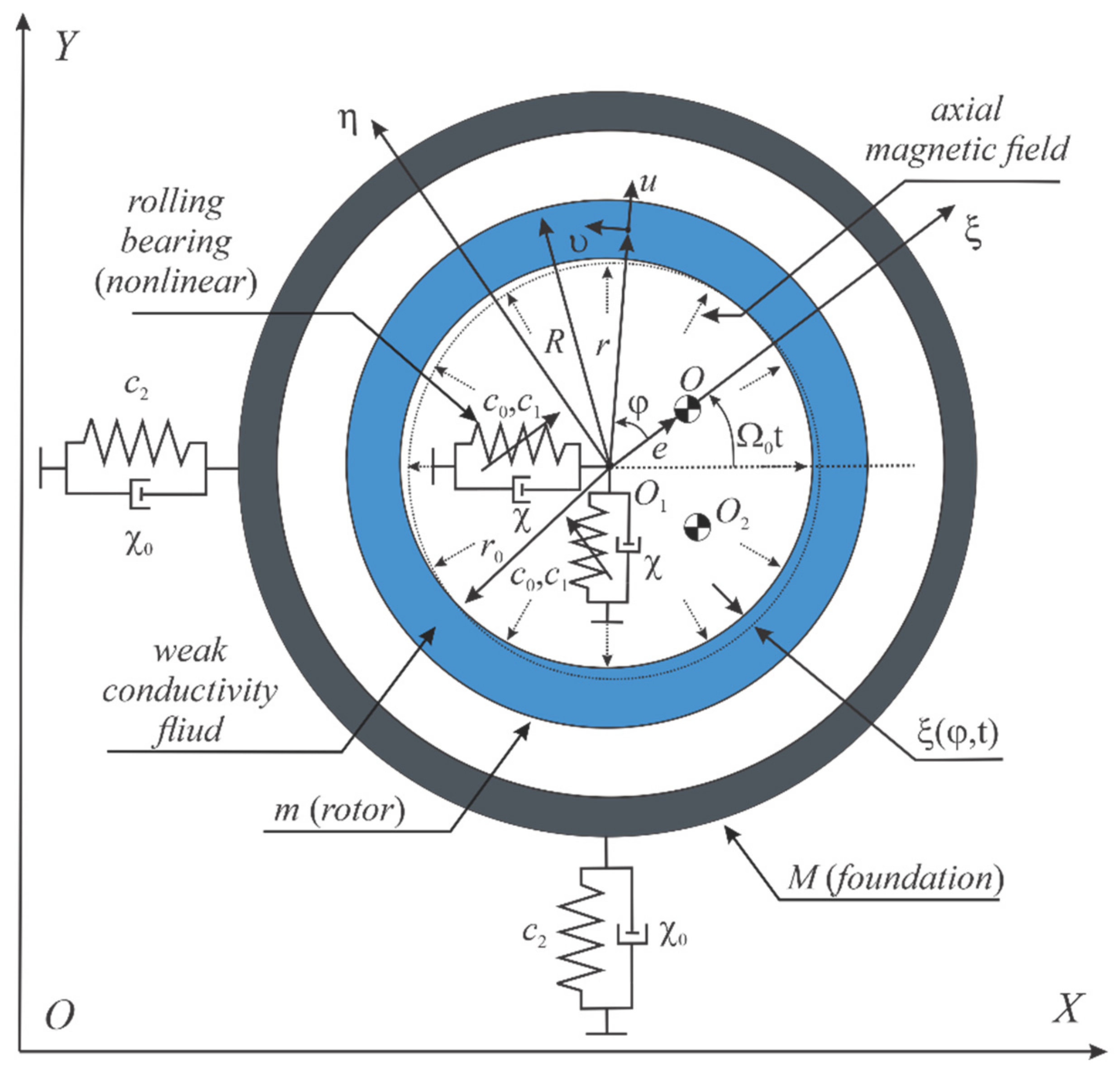
Figure 1. Scheme of a rotor partially filled with a weakly conductive liquid mounted on an elastic foundation.
Applsci 13 12089 g001
Disclaimer/Publisher’s Note: The statements, opinions and data contained in all publications are solely those of the individual author(s) and contributor(s) and not of MDPI and/or the editor(s). MDPI and/or the editor(s) disclaim responsibility for any injury to people or property resulting from any ideas, methods, instructions or products referred to in the content.