Article

The Effect of Vibrations from Racing Cars on the Human Body in FORMULA STUDENT Races

1
Department of Mechanical Engineering, Transilvania University of Brașov, 500036 Brașov, Romania
2
Romanian Academy of Technical Sciences, 030167 Bucharest, Romania
*
Author to whom correspondence should be addressed.
Appl. Sci. 2023, 13(22), 12150; https://doi.org/10.3390/app132212150
Submission received: 22 September 2023 / Revised: 28 October 2023 / Accepted: 6 November 2023 / Published: 8 November 2023
(This article belongs to the Section Mechanical Engineering)

Abstract

:

Featured Application

The results obtained in the study were used by the designers of the racing car with which the Transilvania University of Brașov participated in the Student Formula competitions.

Abstract

During car races, strong vibrations appear in the chassis of the vehicle, due to the high power created by the engine which are then transmitted and, therefore, affect the driver’s condition. The study of these vibrations is a subject frequently addressed by researchers, analyzing the influence of different parameters on the forces to which the pilot’s body or certain sensitive body parts are subjected. In this paper, we analyze the particular case of a racing car made to meet safety requirements in the event of an accident. For the analysis of the forced vibrations induced by the running track, the finite element method was used. This method proved to be a useful and stable modeling and analysis method, validated by practical applications. A standard-equipped racing car with a mannequin inside was studied. Once the natural frequencies of the structure were determined, the response of some points of the mannequin’s body to the movement caused by the running track or the engine was analyzed. Modeling and discretization were performed using well-known classical procedures. The obtained results revealed the parameters that can negatively influence the body of the mannequin which were communicated to the design team. The conclusion of this study is a racing car that was successfully used in Formula Student competitions.

1. Introduction

During car races, the driver’s body endures some extreme forces that, under certain conditions, can have negative effects on the human body. The driver is subject to forces coming from the roadway, which are transmitted through the wheels, suspension system, chassis and seat to the driver’s body. The single-seat chassis used in car racing must ensure the unity of the whole assembly. It must reduce the effect of accelerations and unwanted impacts as well as ensure stability during the race. The constructive solution chosen by the designer of the racing car must ensure the protection of the driver from the effects induced by vibrations on his body.
Some tubular chassis solutions used in racing cars that ensure good protection against vibrations are presented in the following. For example, in [1] a method is presented to realize a project that corresponds to the requirements of such a vehicle. The vibrations that appear in the chassis of such a vehicle represent an important problem, as they cause major discomfort to the driver during the race. The experimental determination of the vibration parameters that appear is described in [2]. The natural frequencies, damping factor and natural modes of vibration for a chassis designed for a racing car are determined. Other results obtained after experimental measurements are presented in [3]. New study, design and optimization methods are addressed in [4,5].
The creation of virtual models allows for the realization of high-performance projects with low costs [6]. These models allow the elimination of some testing steps that were previously done on the physically realized prototype of the vehicle. Such an approach, as in the example presented, allows for significant savings. The weight reduction also has an influence on the vibration behavior of the structure. Some solutions for making structures with reduced weight are presented in [7,8,9]. For the analysis and study of the vibrations of the tubular chassis-dummy assembly, the Finite Element Method (FEM) is, also in this field, a powerful analysis method. For example, the use of the method for the analysis of a real case, a car used in Formula Student, is presented in [10,11]. The Solidwork 3D CAD software is used to describe the geometric model and the analysis is performed with ANSYS 2020. The results obtained with FEM for the analysis of these types of problems are presented [12,13]. During motor racing competitions, the competitors are subjected to intense forces that can have a negative impact on their health and their results. Racing cars generally use a tubular chassis inside which the competitor is positioned. The main problem remains that of frontal and side impacts, as these events have a high probability of occurring in a race [14]. However, there are recommendations and regulations that allow for satisfactory safety [15]. In general, FEM is used for these analyses. Studies on the behavior of a tubular chassis on impact and how it behaves on vibrations are studied in [16,17,18,19]. Other results regarding the dynamic analysis and design of such a chassis are presented in [20,21,22,23,24,25,26,27,28,29]. A simplified approach to the driver–vehicle assembly, considered a two-dimensional system for analyzing the response to vibrations, is given in [30]. The model used is non-linear due to geometric effects. Subsystems are used to study the entire system. This type of approach is imposed by the strongly non-linear behavior of the foam in the composition of the seat material. The natural frequencies and eigenmodes of vibration are obtained in the mentioned paper. The results are verified by experimental measurements and the model proved to be very good for the study undertaken. To obtain reliable results about the factors that can cause damage in the case of human body vibrations, a model is presented in [31]. Especially the points where the human body comes into contact with the environment are analyzed. The study is focused on the pelvis and femur. Vibration analysis is done with FEM. To control vibrations and limit their unwanted effects, it is necessary to design, model, and simulate the vehicle’s suspension system. Suspension systems are responsible for mitigating roadway disturbances. An analysis of a vehicle used in Formula Student races is made in [32]. Finite element analysis is performed using the ANSYS (R) Workbench. For the vibration isolation of the single-seater, a solution was used that consisted of a support made of elastomer used to isolate the vibrations reaching the vehicle structure [33]. The high level of transmissibility of a racing car was highlighted, which is also manifested by the high noise produced by such a vehicle. The factors that determine people’s opinions on the comfort level of the vehicle are physical variables such as temperature, vibrations, air speed, acceleration, light intensity, and noise level. A study that aims to objectify people’s subjective evaluations of comfort is presented in [34]. Based on them, the study of measurable variables at certain points of a mannequin makes it possible to establish comfort indices. The study of the kinematics of the driver’s head and his exposure to accelerations and vibrations is analyzed in [35]. Experimental data for the study was collected using six race drivers. The study also allowed a measurement technique that allows decoupling acceleration in turns from those due to short-term disturbances. Other theoretical models and measurement techniques for the determination of accelerations and vibrations occurring in machines subjected to high forces are presented in [36,37,38,39,40,41,42].
Racing drivers are exposed to intense whole-body vibrations. These vibrations are complex, involving movement along multiple axes in both the sagittal (e.g., vertical) and coronal (e.g., lateral, roll) planes of the human body [43]. Previous research has shown that the human body is a non-linear system, but the vibrations along a single axis have been analyzed by most researchers, as they can give a first-instance characterization of the demands to which the driver can be subjected [44,45,46]. The limits of the different sizes that the human body can bear under the action of vibrations are standardized [47,48].
The study of vibrations was done, on most models, only on the human body (i.e., see [49], where the natural frequencies were determined for a human body). In this work, we tried to cross this limit by studying the racing car–human body assembly. Obviously, such an approach requires increased computing resources, but current technology can provide us with these resources. Numerous works deal with the study of the damping effect that the seats and their material can have on the damping of the vibrations acting on the driver [50,51,52,53,54,55,56,57,58,59,60].
In general, there are few studies that present human behavior during vibrations to which he is subjected while driving a vehicle. The studies are done for relatively low RMS values of the accelerations (3 m/s2). The accessible values to which the human body can be subjected are indicated in [61]. When driving on bumpy roads, drivers and passengers are exposed to extensive vibrations of the whole body and repeated shocks. The vibrations lead to a response of the human body which is generally non-linear.
This paper presents the vibrations of three distinct human body points under various conditions. These are contrasted with one another. The circumstances surrounding a race car are examined, and the amplitudes of three dummy points are determined in the event that the car experiences excitation in three distinct scenarios. Scenarios where we are in the vicinity of resonance vibrations, where the vibrations’ amplitude grows are examined.

2. Materials and Methods

The work studies the influence of the vibrations that occur during the operation of a racing car on the driver. For this, a FEM model is used to describe the chassis–dummy assembly, based on which the dynamic analysis is performed (Figure 1).
A linear vibration analysis is conducted using OPTISTRUCT from Altair Hyperworks package as solver. The elements type used for this analysis is CQUAD4, a shell element with 4 corner nodes with 6 DOF. These element types have been used for most components from the model, less upper and lower arm of suspension that was simulated as CBAR element, an 1D element with 2 end nodes with 6DOF. All materials were considered in the linear domain for free and forced vibration analysis. The interaction between elements was made through tie contact elements node-to-surface with an image card TYPE7.
Three points of the dummy are considered, which are important in determining the influence of vibrations on the driver’s body. In these three points, the accelerations that appear and act on the driver’s body will be determined (Figure 2).
People, as car passengers, are highly sensitive to various shocks from the external environment. People are very vulnerable to mechanical shocks and accelerations and can easily get injured. A car accident, which usually involves dramatic shocks, causes the driver or passenger to endure very high accelerations, which can negatively affect human health and, in extreme cases, can lead to death. The protection of people has become a major concern of car manufacturers and the systems for protecting people in the vehicle have been continuously perfected. Anthropomorphic test devices, called “dummies” (mannequin), were used for testing. However, the current development of computing technologies and numerical methods allows the use of virtual mannequins. These mannequins allow obtaining useful results and conclusions, while studying the influence of numerous parameters.
Dummies used to replace a real driver or passenger in car tests can provide very precise values in terms of kinematics and can give values very close to the real ones, especially in the case of accelerations. For the study of vibrations, accelerations represent an important aspect, so a study conducted with dummies can lead to good results. Different types of mannequins have been developed and there are even standards with their dimensions and weights. There are customized mannequins for men, women and children. There are also specific mannequins made for frontal or side impact. For the study of vibrations, such a dummy is presented in [62,63,64,65].
There are numerous studies that present the behavior of mannequins in experiments and their behavior in shocks. Regarding the important but realistic example of racing cars, helpful findings can be found in [44,45]. In such tests, a standard adult mannequin is used, with the average, in the USA, weight and size for adults. Obviously, the use of a mannequin can represent a disadvantage for research because a mannequin cannot behave exactly like a human body, but at the same time it avoids injuring people during experiments. The use of corpses in such research did not give satisfactory results [66].
In the present study, a virtual mannequin was used for the analyzes and the research carried out. It was discretized, along with the chassis of the vehicle, using FEM. Fixing the mannequin to the seat is done with the safety belt. A FE Hybrid III 50th male mannequin was used in the work. This represents the average adult male [46].
Figure 3, Figure 4 and Figure 5 show three cases that were studied within the work: in the first case, an excitation of a rear wheel is considered, in the second case, an excitation of a front wheel is considered, and in the third, the excitation created by the engine is considered. The first two types of excitations are given by the running path (road) and the third variant offers the excitations created by the engine. These situations are the main types of excitations encountered in most motor vehicles. In the study, we wanted to see how these excitations influence the values of the three-point accelerations of the dummy.

3. Results

The geometry and dimensions are presented in Figure 6.
Based on the car-impact attenuator-driver model, the natural frequencies of the system were determined. Their values are presented in Table 1. It is found that there are 64 natural frequencies located below 100 Hz. The system thus becomes vulnerable to excitations below this frequency, since the number of natural frequencies is high in this field. The weight of the car is approximately 200 kg, not including the dummy. The weight of the dummy is 80 kg.
The tubular bars from the chassis are connected each other with welds and the sectional properties are applied according to Figure 7 below.
The CAD model was realized in the Solid Works and exported as STEP file to the Hypermesh 2019 software, which was used as preprocessor for FEA analysis. The model has 80,792 modes for 81,069 elements. The behavior of the system in the case of excitations with different frequencies is of interest. Therefore, based on the current model, the system was excited at the rear wheel and at the front wheel. Then, the excitations coming from the engine were considered. Figure 8 present the displacements in the first case considered.
Figure 9 shows the stresses in the tubular chassis to a frequency situated in the resonance area of the system and Figure 1 the displacements.
The vertical displacements of these points are presented, for the first cases, in Figure 10 when the system is excited with the 12th eigenfrequency.
Figure 11 presents the displacements in the second case studied. In Figure 12 is presented the von Mises stress for an excitation frequency equal with the 13th natural frequency in the second excitation case.
Vertical displacements of these points are presented, in the second case, in Figure 13, where the system is excited with the 12th eigenfrequency.
Figure 14 presents the displacements in the third case. In Figure 15, von Mises stresses an excitation frequency equal to the 13th natural frequency in the third excitation case.
In the second case, the vertical displacements of these points are presented, for an excitation with the 13th eigenfrequency, in Figure 16.
The points where the stresses are maximum are visible due to these three cases of excitation, which display where special attention must be paid to the design.
In what follows, we study the accelerations that the head of the driver can have, while traveling on an uneven road or due to the operation of the engine.
Other cases are presented in the Appendix A.
Figure 17, Figure 18 and Figure 19 show the amplitudes of the accelerations in the case of excitations at the rear wheel, the front wheel and in the case that the excitations are caused by the engine. The excitation is 1 mm the amplitude of the vibration.
For certain frequencies, these amplitudes can exceed 10 g and can become dangerous for the pilot. However, we must take into account the fact that during the race, the situations, road bumps and excitations are constantly changing, so the duration during which the driver is subjected to such demands is very short. The point for which the accelerations were determined was the head. The RMS for the three types of vibrations (lateral, longitudinal, vertical) were: 0.77 g; 0.51 g; 2.18 g, respectively, where g is the gravitational acceleration for the first case of excitation (rear wheel).
RMS for the three types of vibrations (lateral, longitudinal, vertical) were: 0.31 g; 0.26 g and 0.78 g, respectively, for the second case of excitation (rear wheel). For the third case, when the excitation is produced by the engine the RMS were: 2.99 g; 0.28 g and 3.84, respectively. This analysis shows that the accelerations produced by the engine have the greatest impact on the driver.

4. Discussion and Conclusions

Analyzing the results obtained in the present study, the following conclusions can be formulated:
  • The movement of vehicles is accompanied by the permanent appearance of vibrations and shocks. These vibrations are transmitted to the level of the sprung and unsprung masses of the vehicles, considerably influencing the comfort of the passengers and the durability of the components of the body, suspension, transmission and engine.
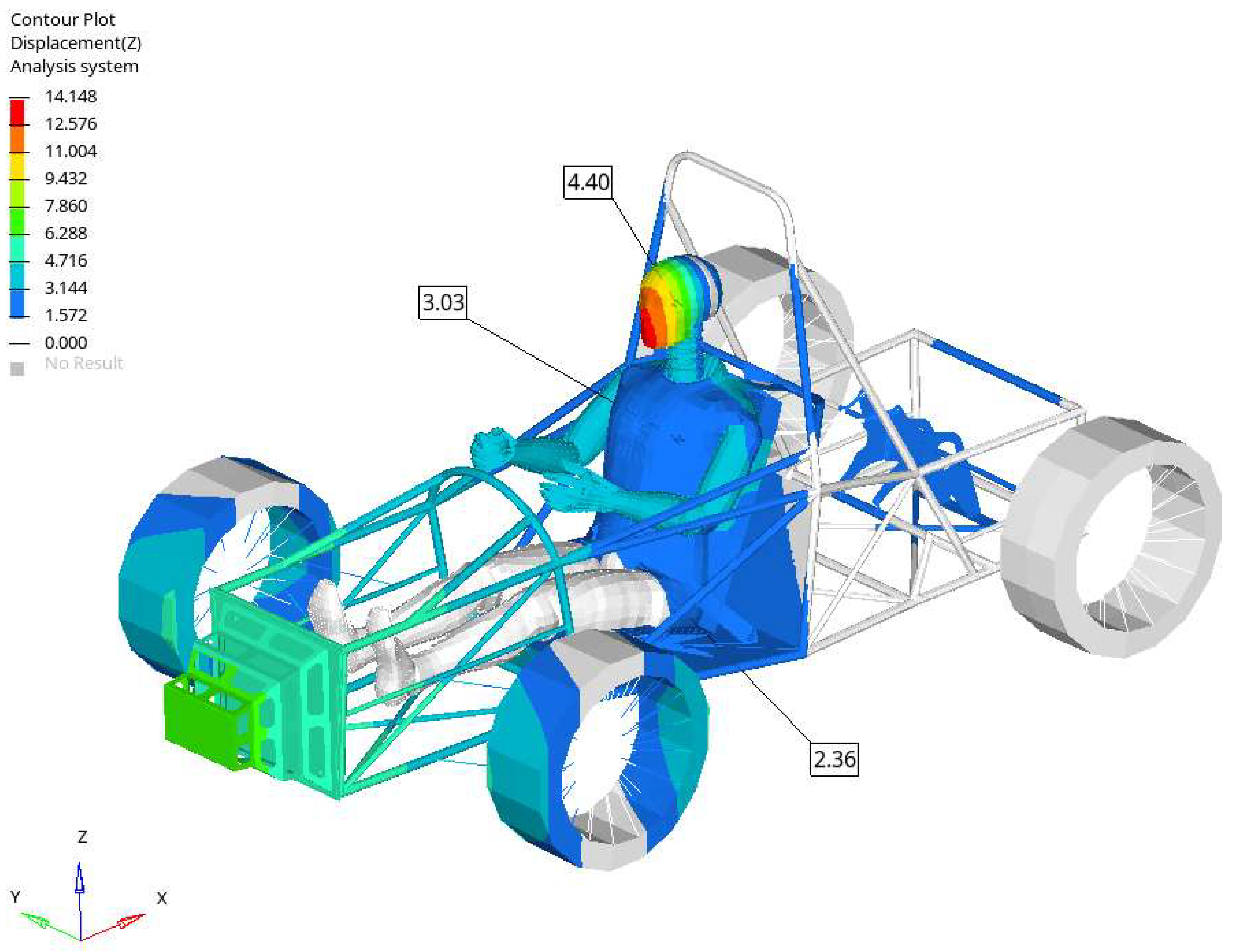
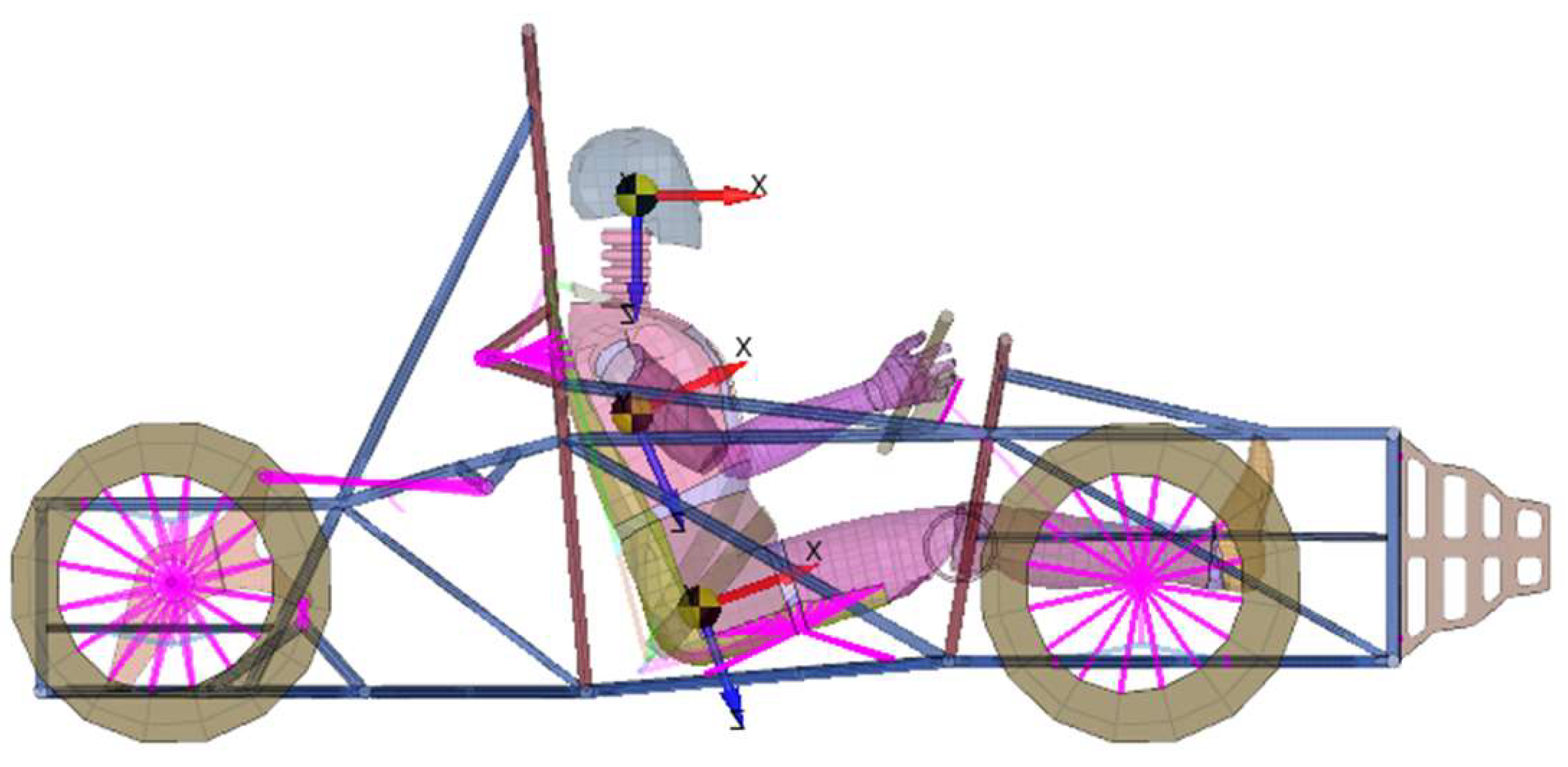
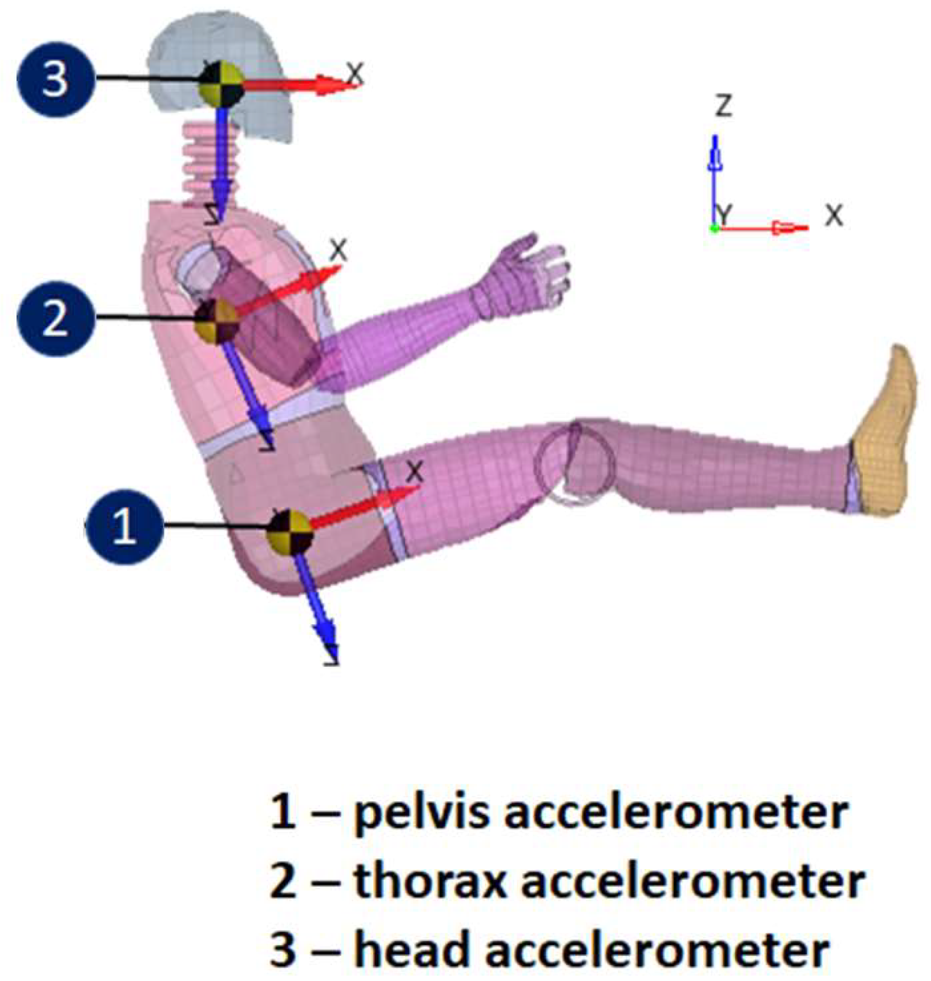
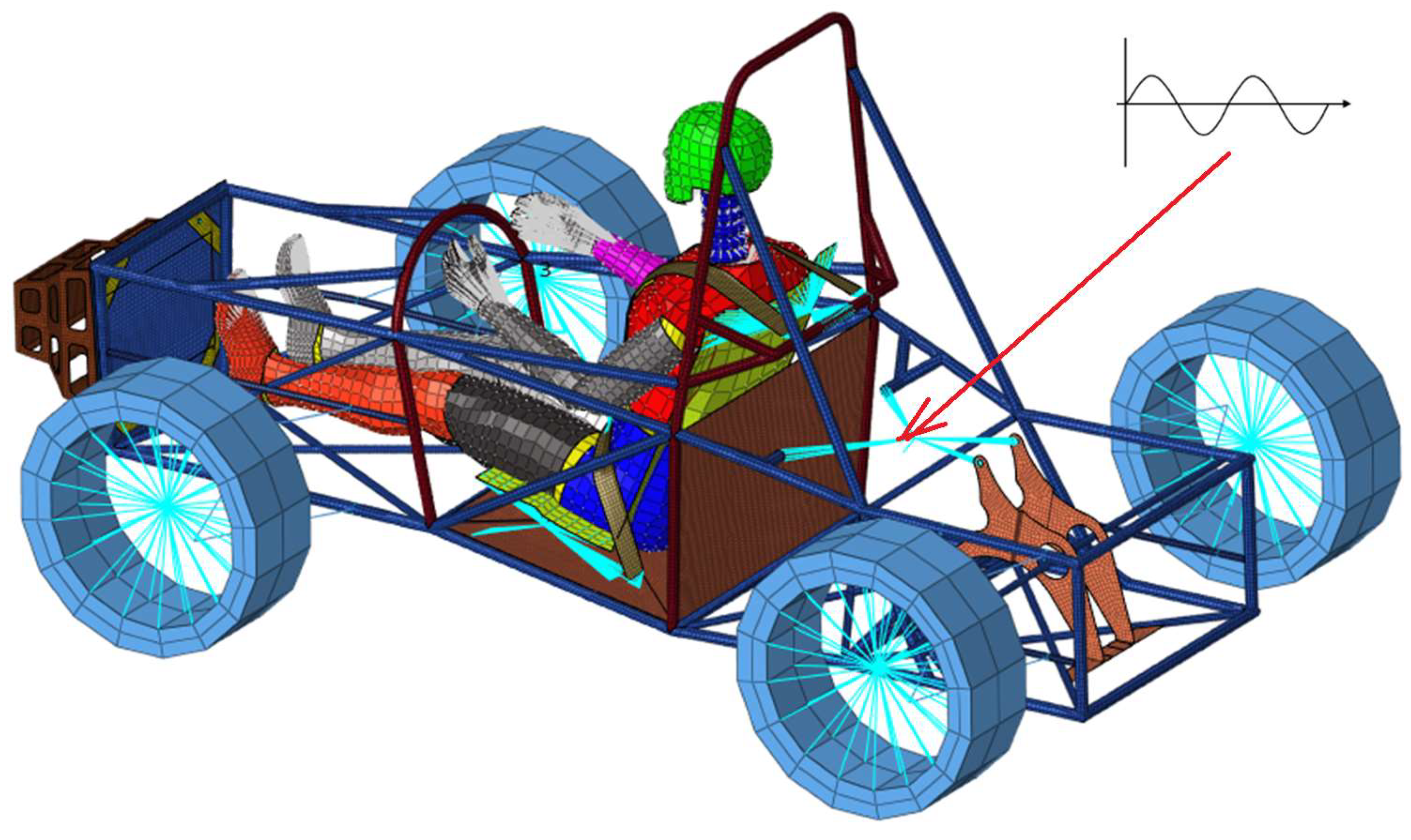
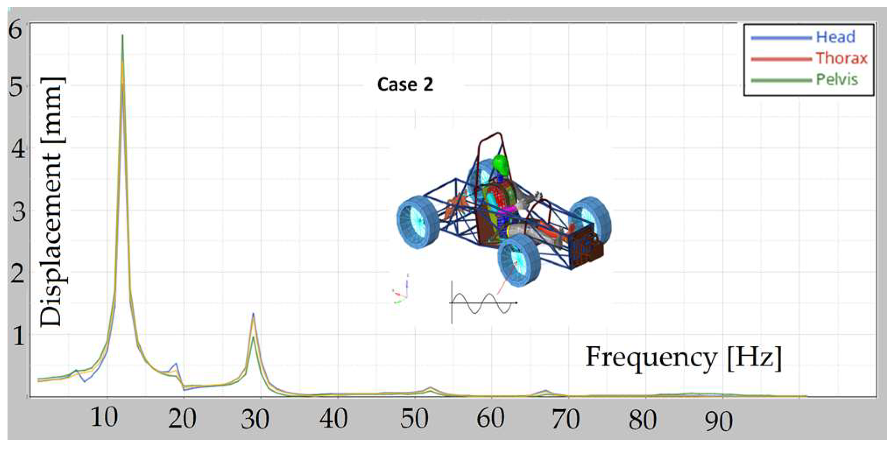
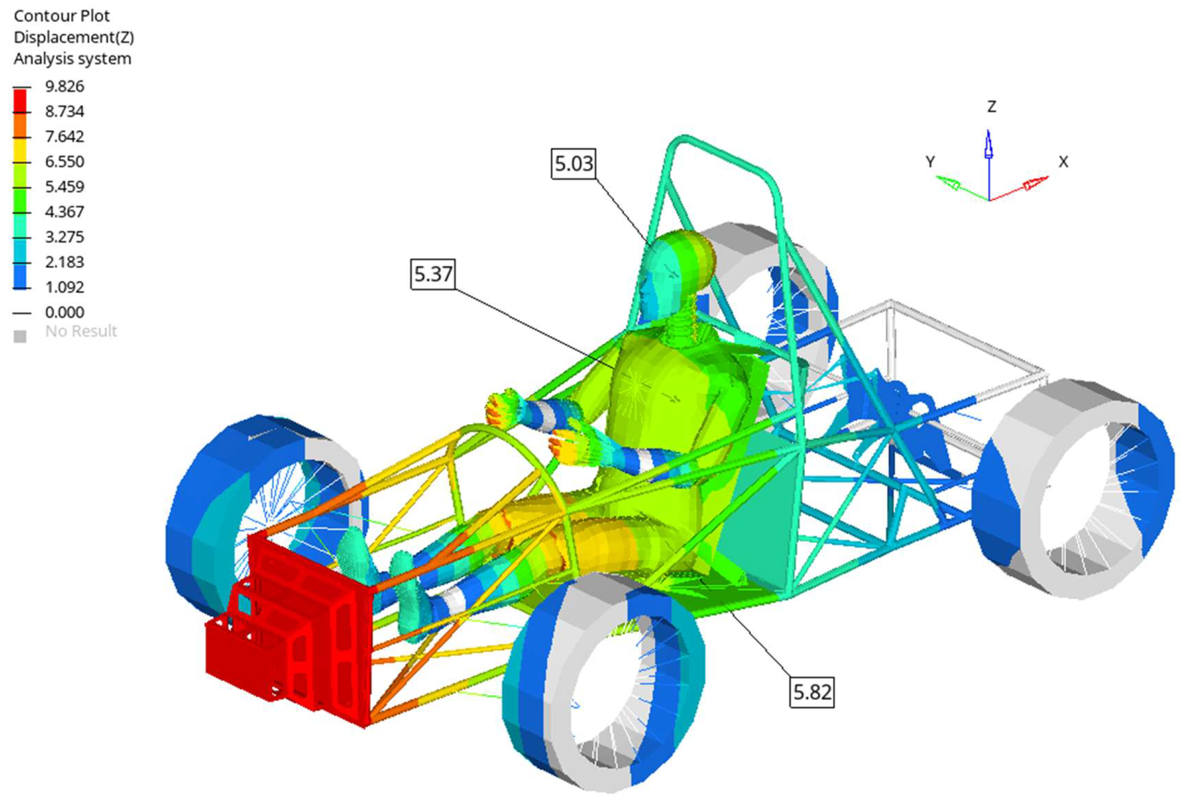
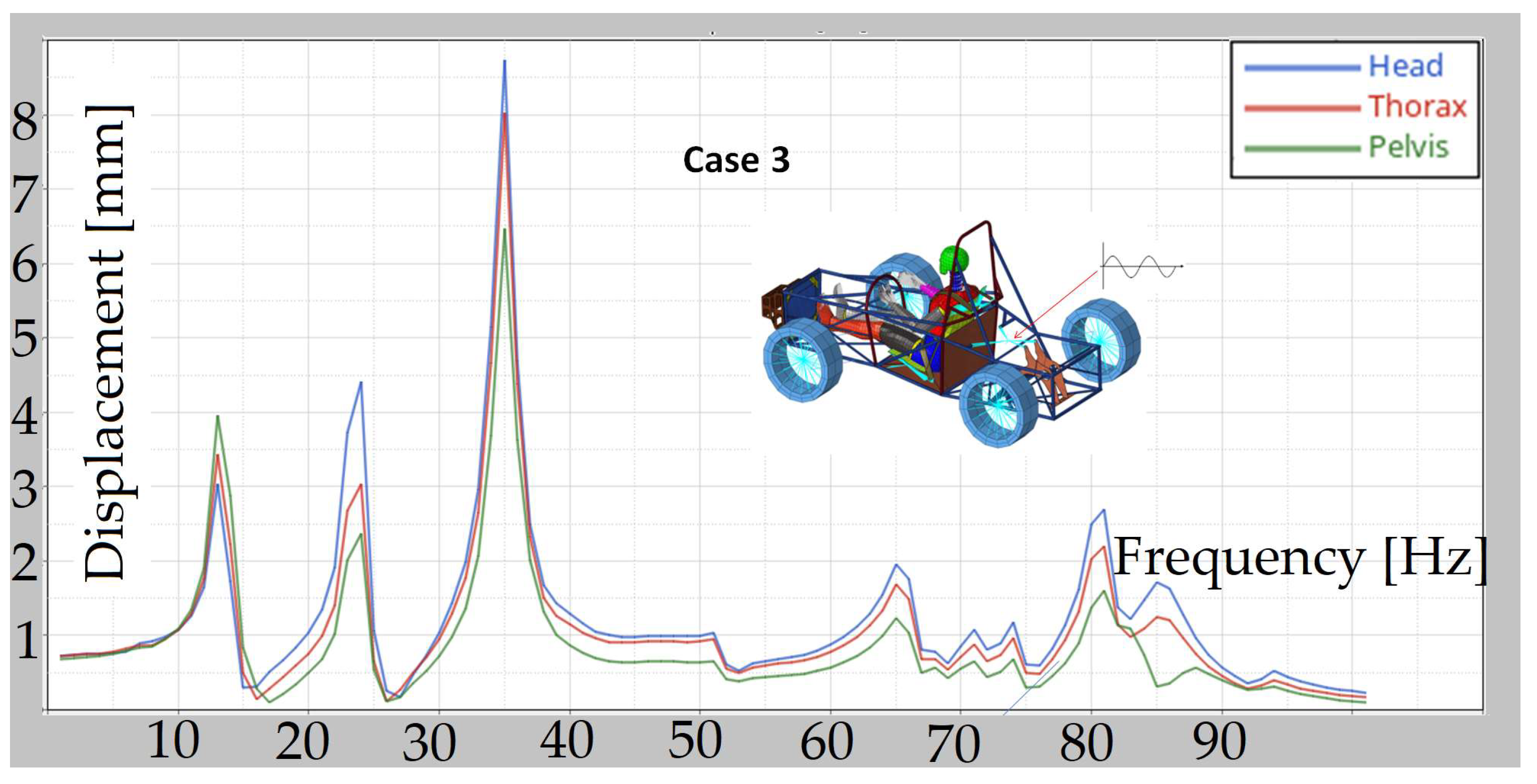
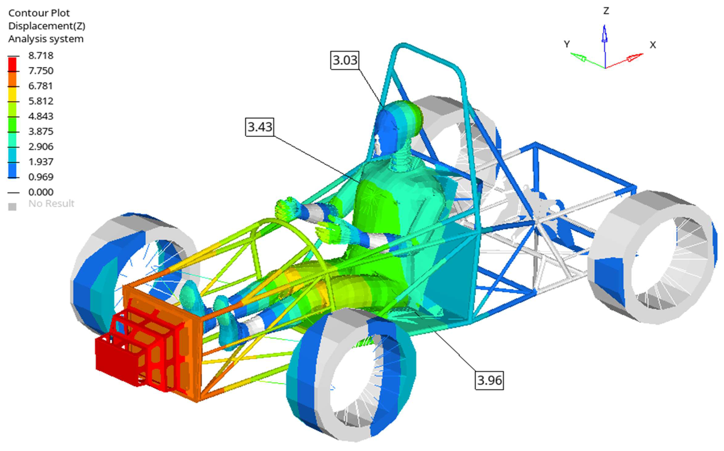
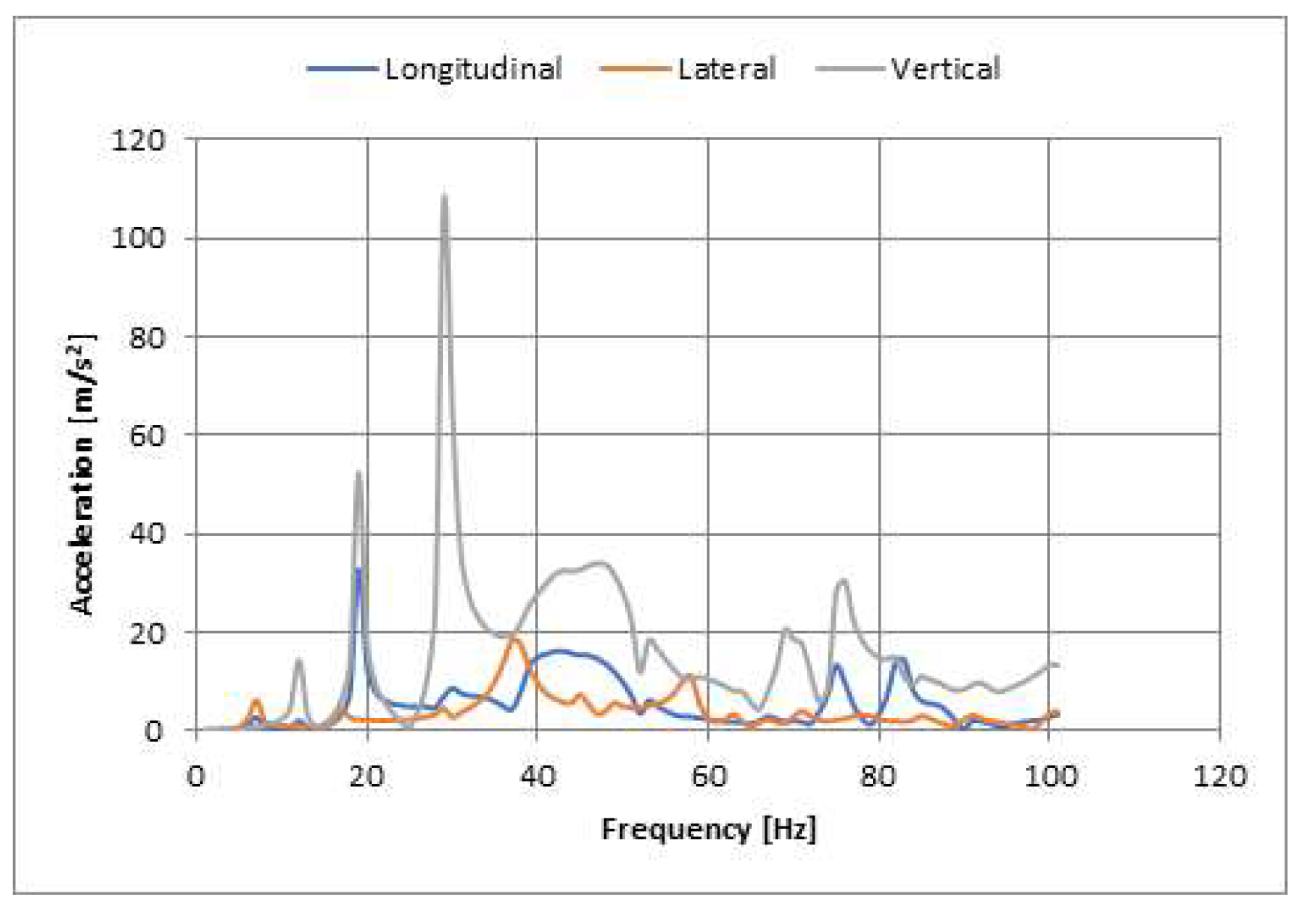
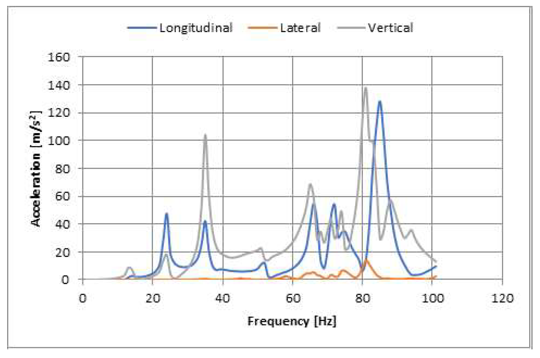
  • In the case study carried out, the way these vibrations are felt in the head, thorax and pelvis of a kart driver was studied based on perturbations coming from various sources, such as road irregularities or engine excitations. These excitations were considered sinusoidal with a unit amplitude of displacement. The range considered for the forced vibration study was 0–100 Hz.
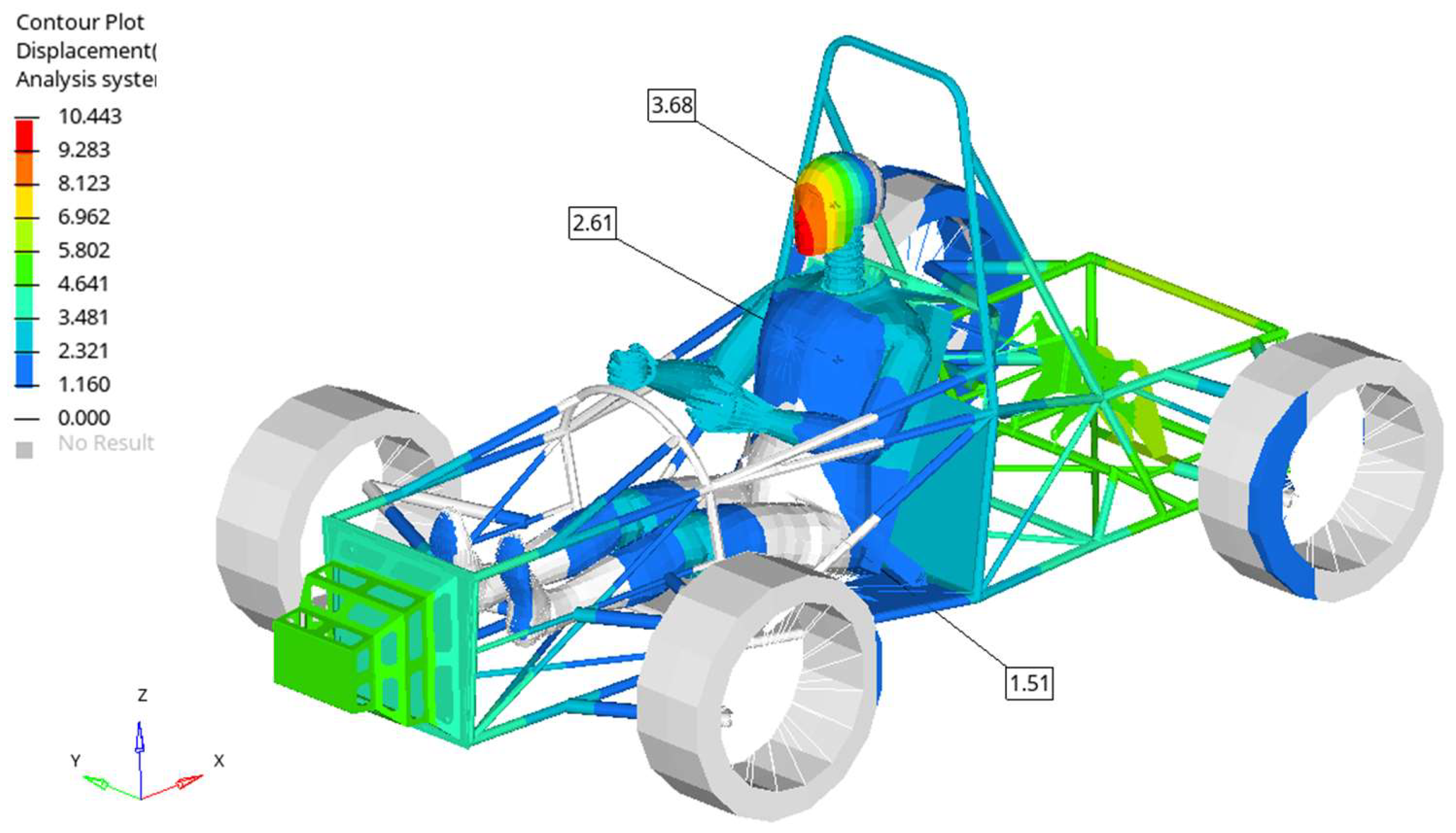
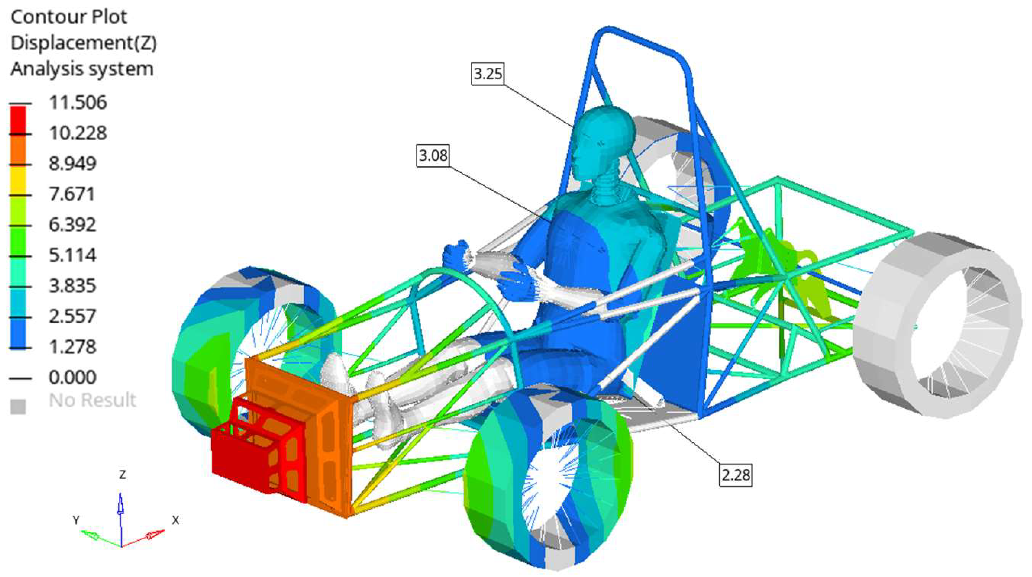
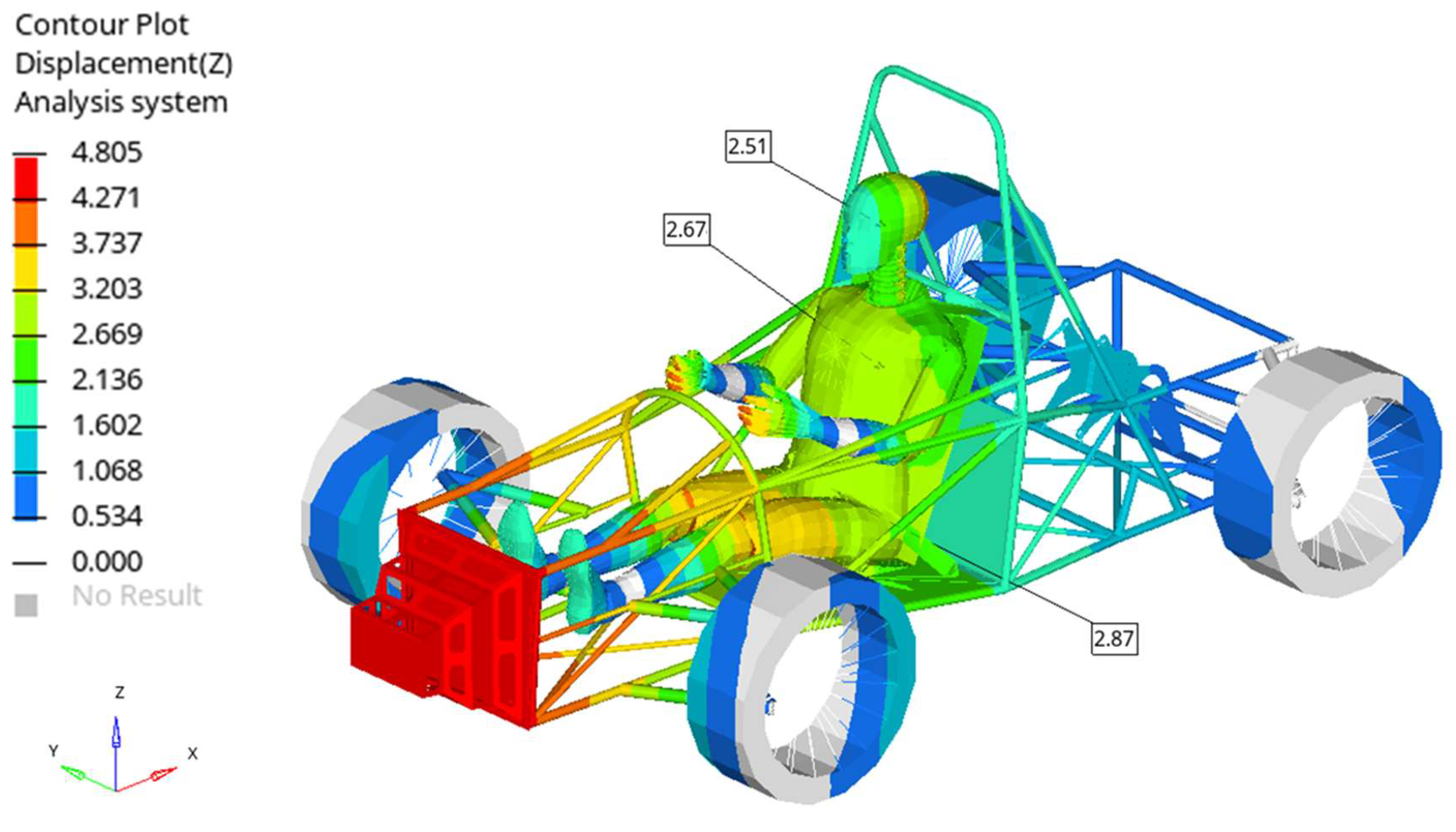
  • As can be seen from the results, the largest displacements of the analyzed cases were obtained in case 3 near the eigenmode 35. The obtained value was approximately 8.75 mm at head level. Slightly lower values on the same frequency were obtained on the chest and pelvis.
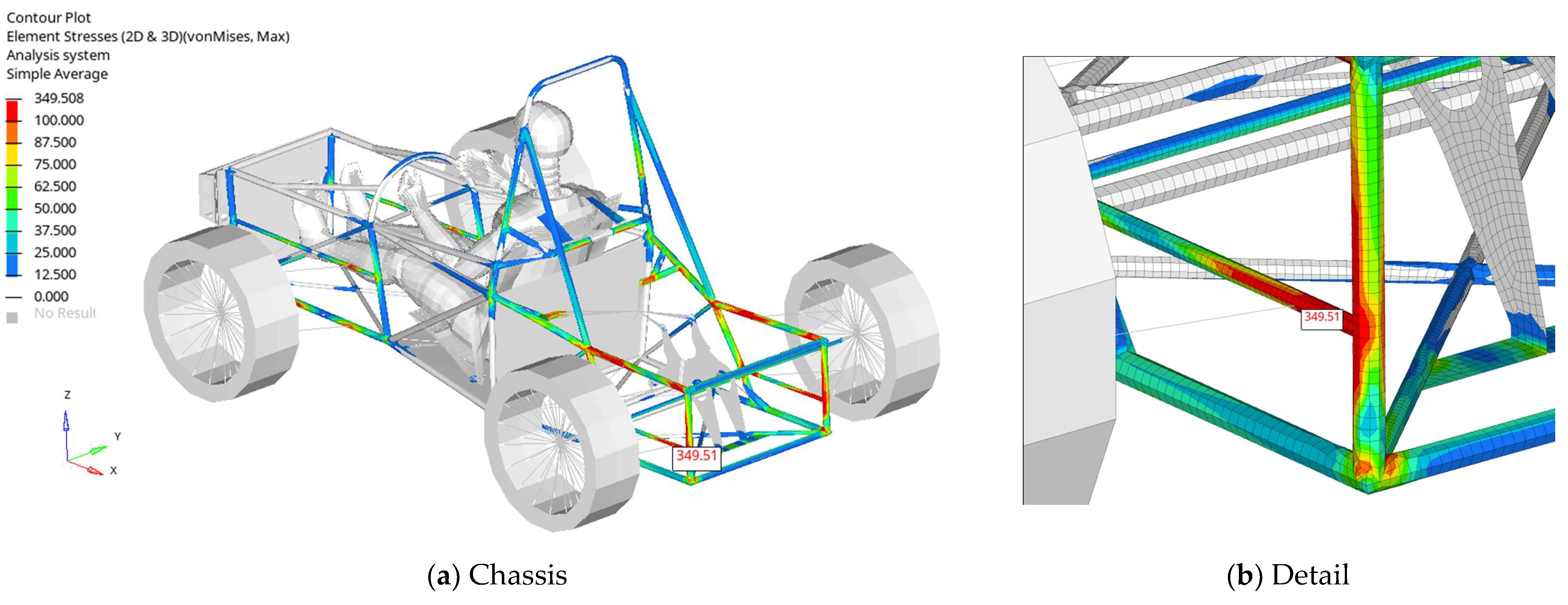
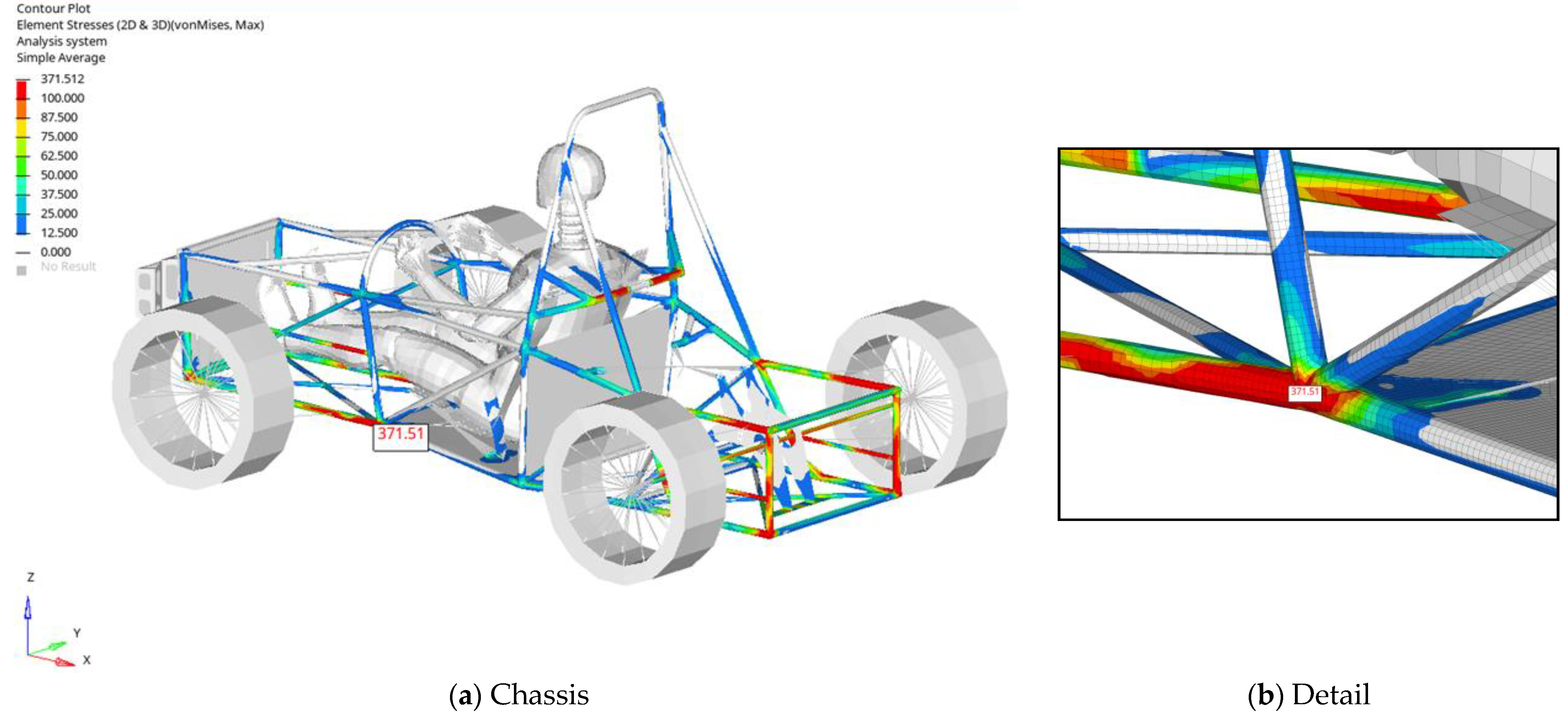
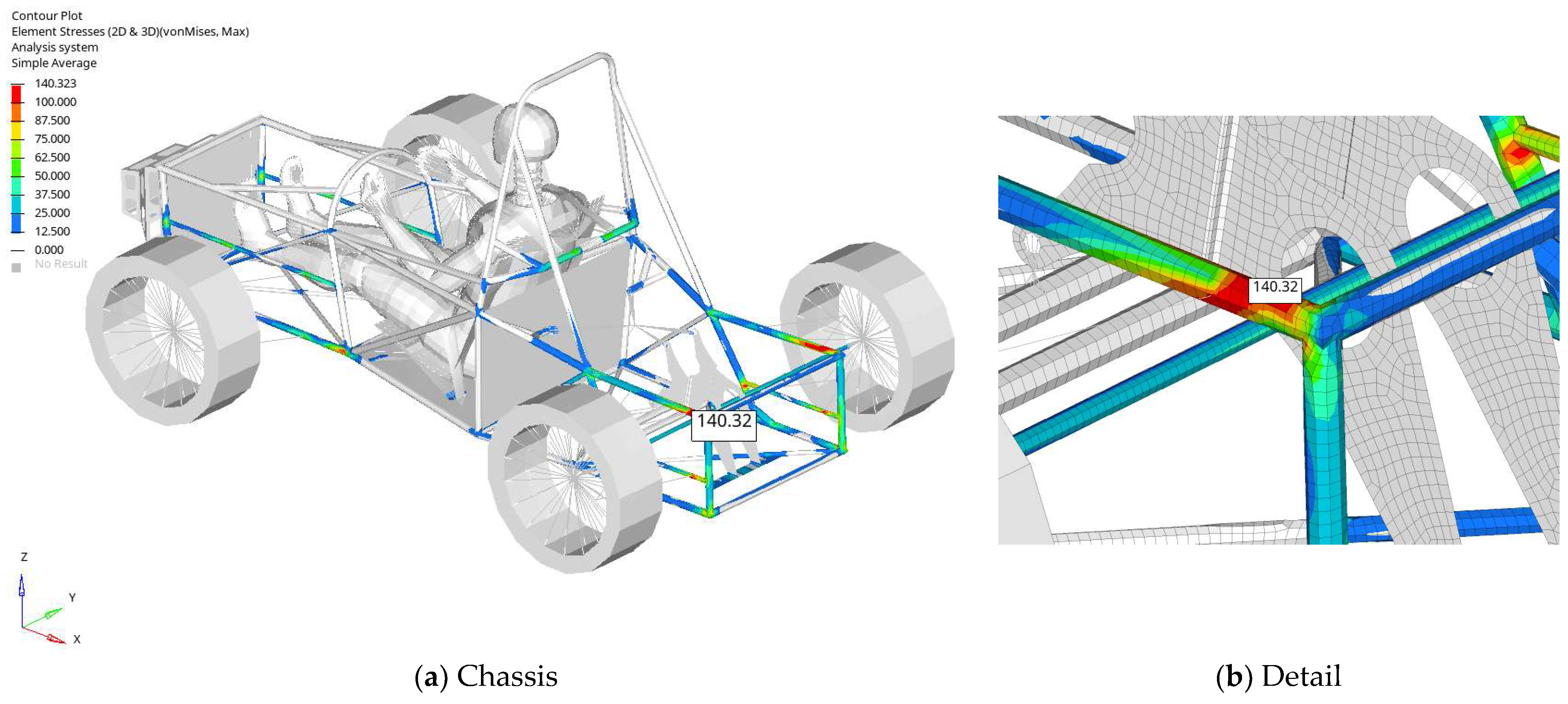
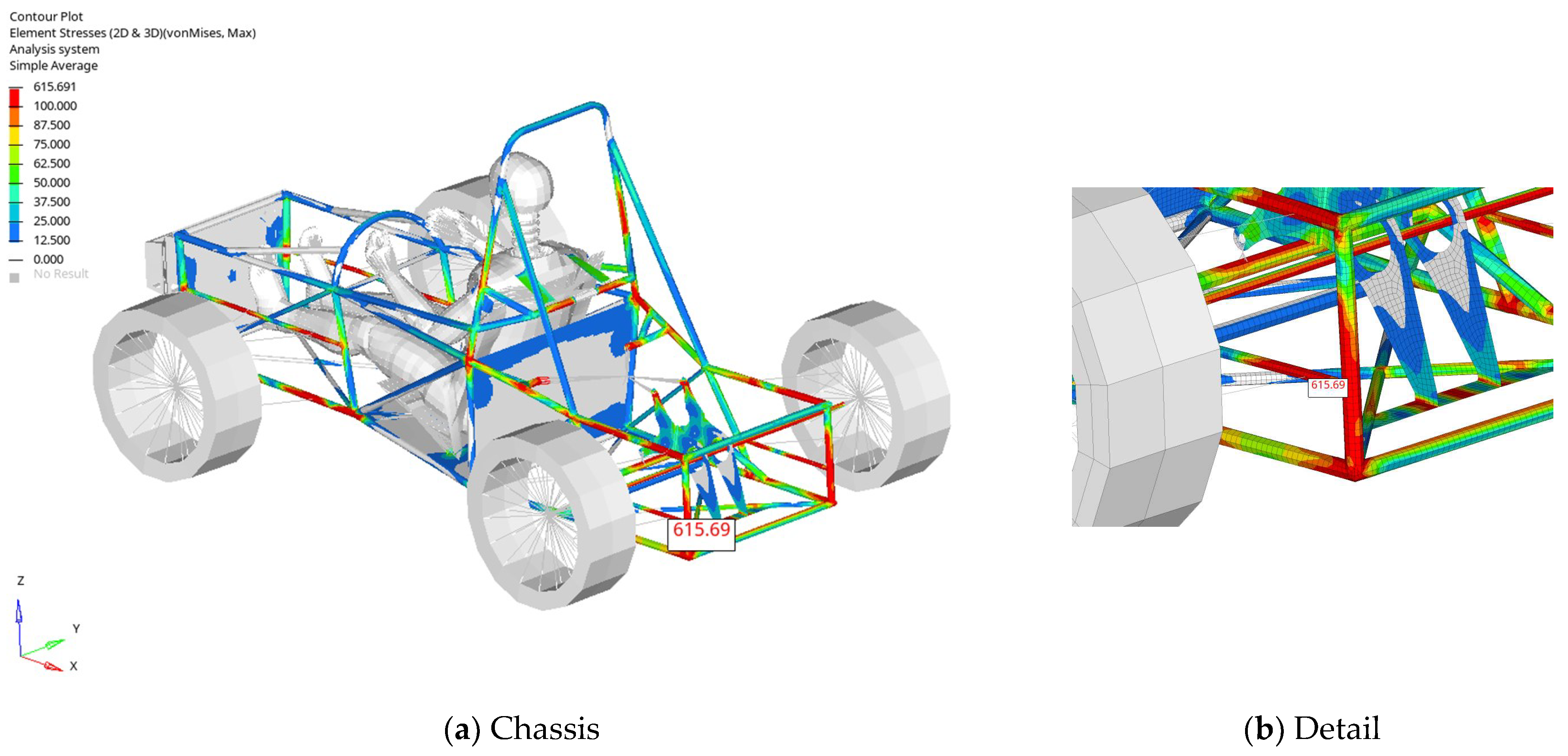
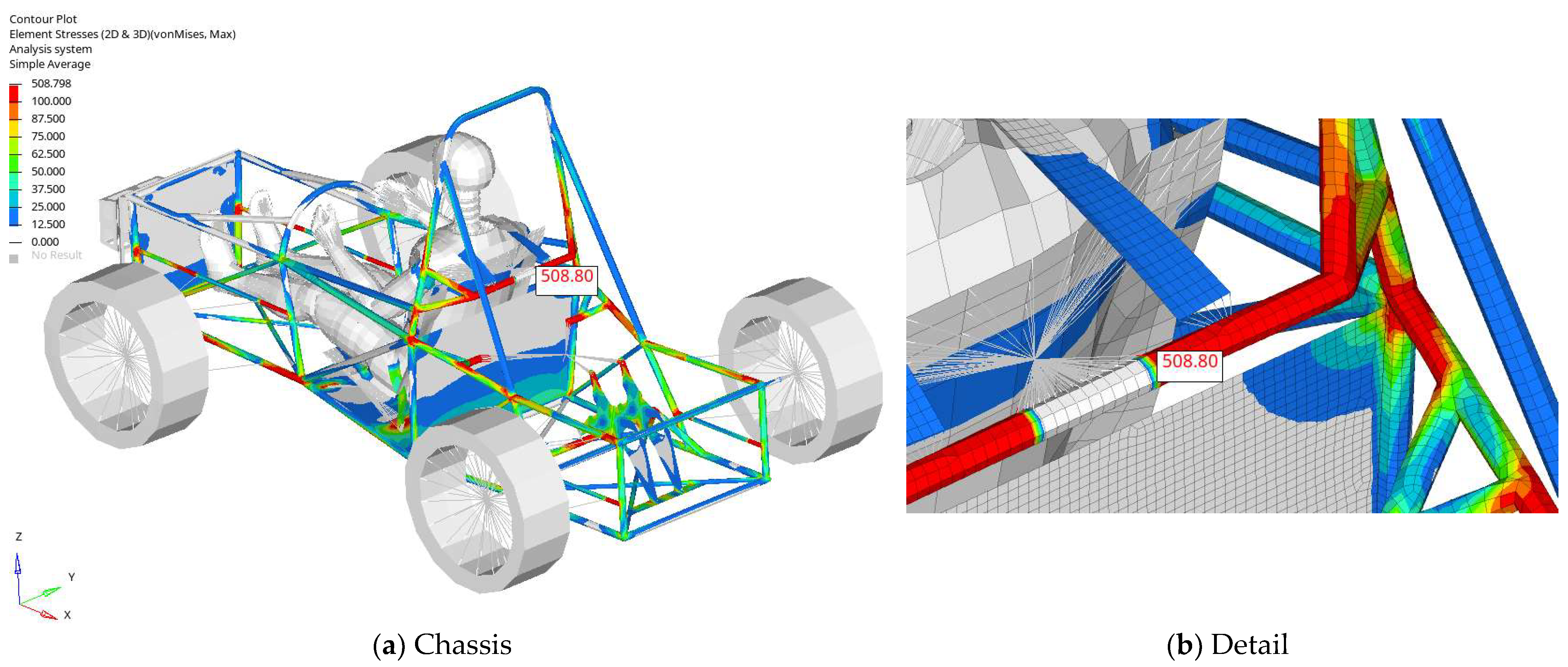
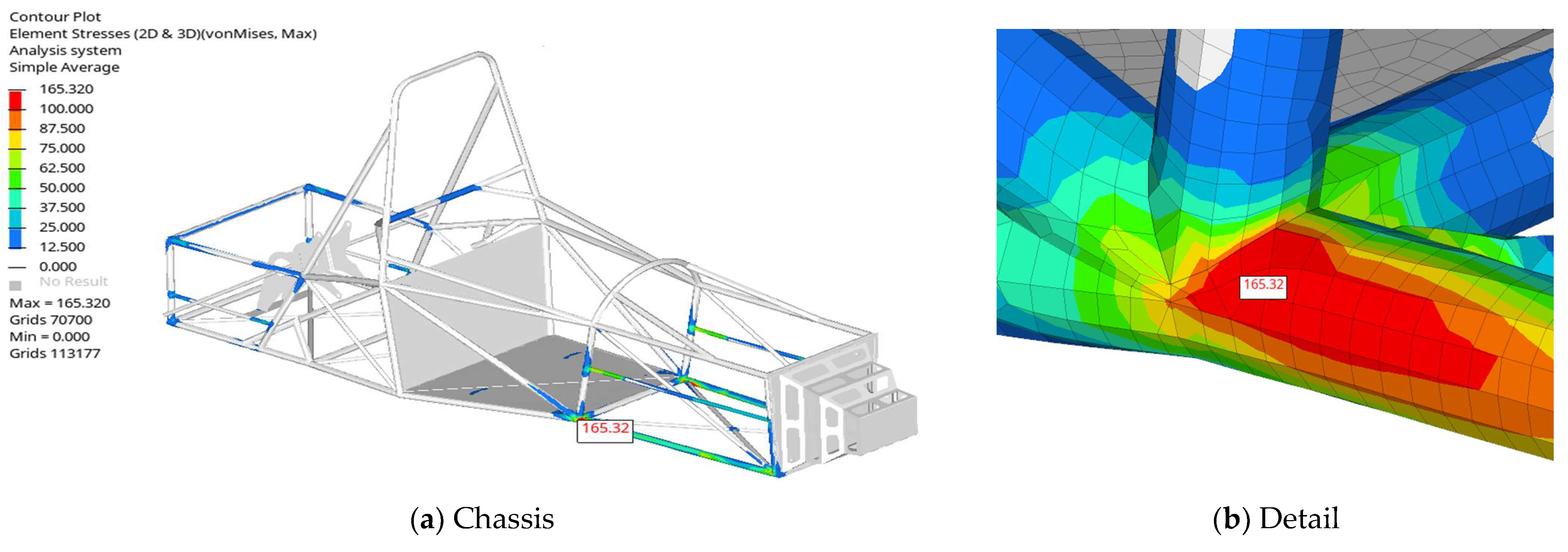
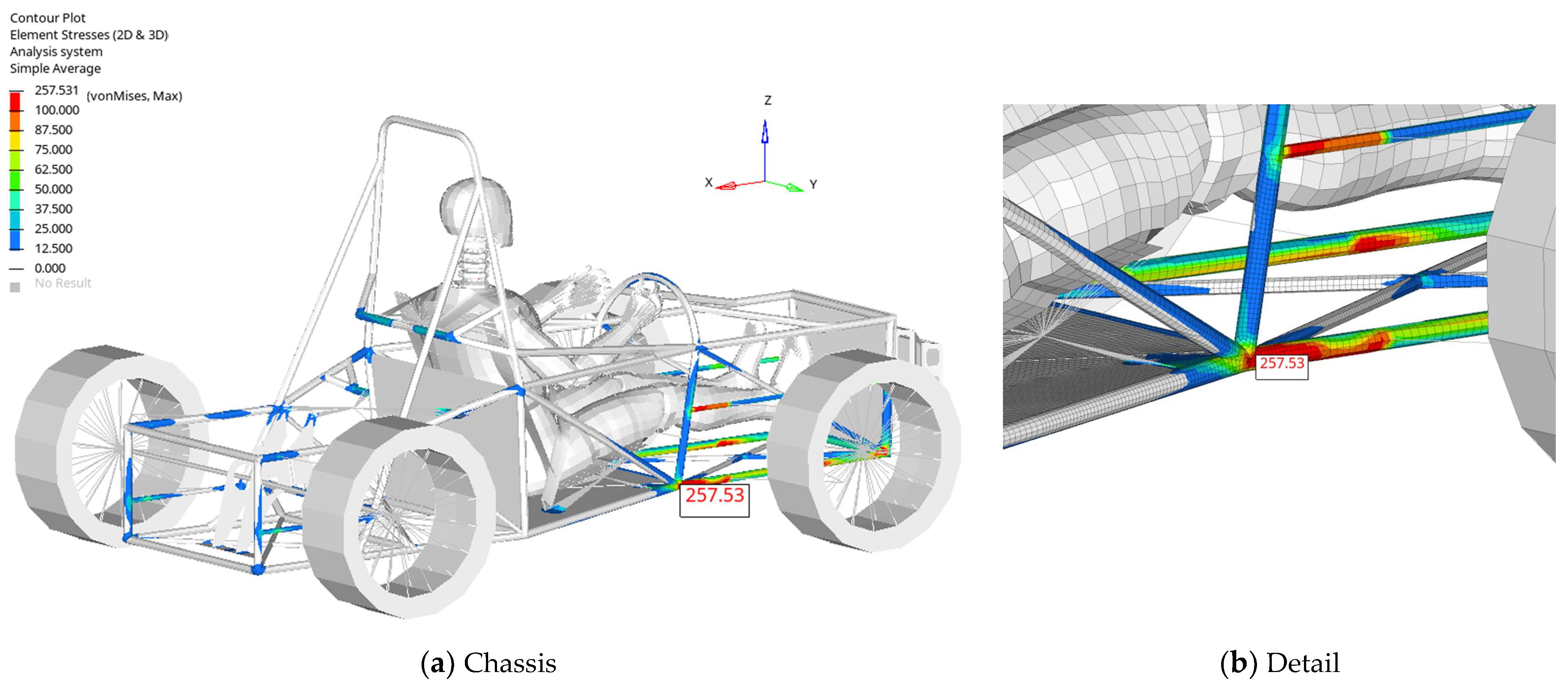
  • If we analyze the stress level in the chassis structure, it can be seen that a high level of stress appears in the area where the seat belt is fastened. Since the connection between the belt and the chassis structure is made through rigid connections that introduce infinite rigidity, this value is actually lower since the components that make the belt-chassis connection are flexible.
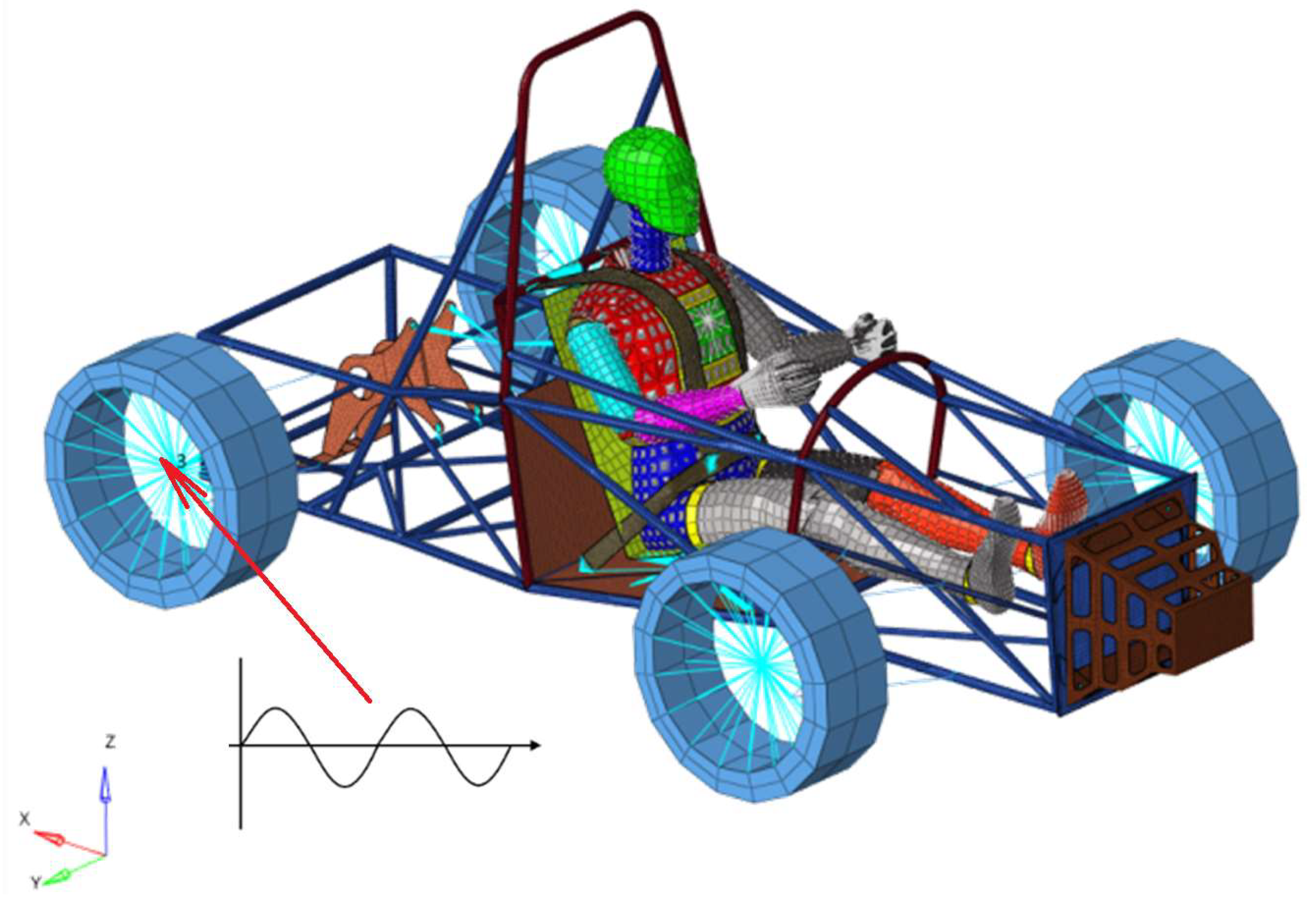
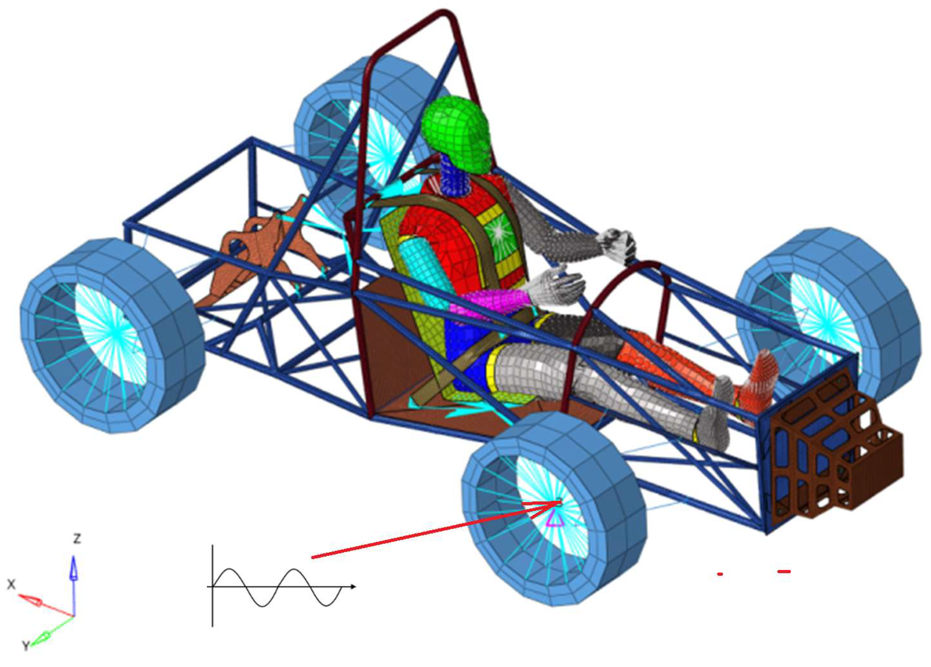
  • For the excitation applied to the rear wheels (left or right wheel), the largest displacement responses at head level were obtained on eigenmodes 19 and 29. The values are about 3.5 mm, significantly lower than those obtained in case 3.
  • For the excitations applied to the front wheels, the response values of the displacements at the dummy head level are 6 mm on the normal mode vibration 12, somewhere between those from the other excitation sources analyzed.
  • As a final conclusion, from all excitation sources surveyed, it seems that the highest output displacement values on the dummy were obtained for the third case with excitation applied to the engine zone. Additionally, from a structural point of view, the highest stress level is obtained from this case, too.
A desire that was communicated to the designers of this racing car was to create a connection between the engine and the chassis that ensures the lowest possible transmission of vibrations to the driver. The goal of the paper is to emphasize the response of a dummy under some external perturbations that come from traffic/engine on the chassis structure/dummy, in race conditions. As is known, the amplitude and intensity of vibrations, as well as the driver’s prolonged exposure to them, can lead to wear of the nervous system and premature aging. The intention of this article is to provide some information related to these responses at the dummy level in various scenarios of disturbances coming from external sources.
During car races, the driver is subjected to significant forces, curves, passing over obstacles, acceleration, and braking. These forces can damage the driver’s health if they exceed certain values. There are standards that give a series of imposed values [47,48]. However, in order to ensure the running of a race without the driver suffering forces that could endanger their health, a detailed study is required where doctors and engineers cooperate. Our study highlights the existence of such potentially harmful accelerations if the human body is subjected to them for a longer time. More thorough investigation and longer-term modeling are needed to determine the impact on human health. We propose this approach in future research.

Author Contributions

Conceptualization, C.I. and V.S.; methodology, C.I. and V.S.; software, C.I. and V.S.; validation, C.I. and V.S.; formal analysis, C.I. and V.S.; investigation, C.I. and V.S.; resources, C.I. and V.S.; data curation, C.I. and V.S.; writing—original draft preparation, C.I. and V.S.; writing—review and editing, C.I. and V.S.; visualization, C.I. and V.S.; supervision, C.I. and V.S.; project administration, C.I. and V.S.; funding acquisition, C.I. and V.S. All authors have read and agreed to the published version of the manuscript.

Funding

The APC was funded by Transilvania University of Brasov.

Institutional Review Board Statement

Not applicable.

Informed Consent Statement

Not applicable.

Data Availability Statement

The data presented in this study are available on request from the corresponding author. The data are not publicly available due to the data obtained in our study being used by the design team to design the prototype of the vehicle that the University Transilvania of Brasov intends to participate in the following formula Student races.

Conflicts of Interest

The authors declare no conflict of interest.

Appendix A

In the first case, an excitation of a rear wheel is considered. It is considered an excitation with the 19th eigenfrequency.
Figure A1. Von Mises stress for an excitation frequency equal with the 19th natural frequency for the first excitation case.
Applsci 13 12150 g0a1
Figure A2. Z-displacement in mm for an excitation frequency equal with the 19th natural frequency.
Applsci 13 12150 g0a2
In the second version of the case 1 an excitation with the 29th eigenfrequency is considered.
Figure A3. Von Mises stress for an excitation frequency equal with the 29th natural frequency for the first excitation case.
Applsci 13 12150 g0a3
Figure A4. Z-displacement in mm for an excitation frequency equal with the 29th natural frequency in the first excitation case.
Applsci 13 12150 g0a4
In the second case, an excitation of a front wheel is considered. It is considered an excitation with the 29th eigenfrequency.
Figure A5. Von Mises stress for an excitation frequency equal with the 29th natural frequency in the second excitation case.
Applsci 13 12150 g0a5
Figure A6. Z-displacement in mm for an excitation frequency equal with the 29th natural frequency in the second excitation case.
Applsci 13 12150 g0a6
In the third case, in the first scenario, an excitation of the engine is considered. It is considered an excitation with the 24th eigenfrequency.
Figure A7. Von Mises stress for an excitation frequency equal with the 24th natural frequency in the third excitation case.
Applsci 13 12150 g0a7
Figure A8. Z-displacement in mm for an excitation frequency equal with the 24th natural frequency in the third excitation case.
Applsci 13 12150 g0a8
In the third case, in the second scenario, an excitation of the engine is considered. It is considered an excitation with the 35th eigenfrequency.
Figure A9. Von Mises stress for an excitation frequency equal with the 35th natural frequency in third excitation case.
Applsci 13 12150 g0a9
Figure A10. Z-displacement in mm for an excitation frequency equal with the 35th natural frequency.
Applsci 13 12150 g0a10

References

  1. Gobbi, M.; Mastinu, G.; Doniselli, C. Optimising a car chassis. Veh. Syst. Dyn. 1999, 32, 149–170. [Google Scholar] [CrossRef]
  2. Sani, M.S.M.; Rahm2an, M.M.; Noor, M.M.; Kadirgama, K.; Izham, M.H.N. Identification of Dynamics Modal Parameter for Car Chassis. IOP Conf. Ser. Mater. Sci. Eng. 2011, 17, 012038. [Google Scholar] [CrossRef]
  3. Silva, A.F.; Mendes, P.M.; Correia, J.H.; Goncalves, F.; Ferreira, L.A.; Araujo, F.M.; Ferreira, L.A.; Araujo, F.M. Inner Car Smart Flooring for Monitoring Chassis Deformation. In Proceedings of the 8th IEEE Conference on Sensors, Christchurch, New Zealand, 25–28 October 2009; p. 1587. [Google Scholar]
  4. Chianola, S.; Gadola, M.; Leoni, L.; Resentera, M. On the design of a low-cost racing car chassis. In Proceedings of the DESIGN 2002: 7th International Design Conference, Dubrovnik, Croatia, 14–17 May 2002; Volume 1–2, pp. 1035–1040. [Google Scholar]
  5. bin Ab Razak, M.S.; bin Hasim, M.H.; bin Ngatiman, N.A. Design of Electric Vehicle Racing Car Chassis using Topology Optimization Method. MATEC Web Conf. 2017, 97, 01117. [Google Scholar] [CrossRef]
  6. Woo, S.; Ha, Y.; Yoo, J.; Josa, E.; Shin, D. Chassis Design Target Setting for a High-Performance Car Using a Virtual Prototype. Appl. Sci. 2023, 13, 844. [Google Scholar] [CrossRef]
  7. Juraeva, M.; Ryu, K.J.; Noh, S.H.; Song, D.J. Lightweight material for the speed reducer housing of a car chassis. J. Mech. Sci. Technol. 2017, 31, 3219–3224. [Google Scholar] [CrossRef]
  8. Feraboli, P.; Masini, A.; Bonfatti, A. Advanced composites for the body and chassis of a production high performance car. Int. J. Veh. Des. 2007, 44, 233–246. [Google Scholar] [CrossRef]
  9. Mat, M.H.; Ab Ghani, A.R. Design and Analysis of ‘Eco’ Car Chassis. Procedia Eng. 2012, 41, 1756–1760. [Google Scholar] [CrossRef]
  10. Zaman, Z.I.; Basaruddin, K.S.; Basha, M.H.; Abd Rahman, M.T.; Daud, R. Finite element prediction on the chassis design of UniART4 racing car. AIP Conf. Proc. 2017, 1885, 020110. [Google Scholar] [CrossRef]
  11. Tsirogiannis, E.C.; Stavroulakis, G.E.; Makridis, S.S. Optimised ultrafast lightweight design and finite element modelling of a CFRP monocoque electric chassis. Int. J. Electr. Hybrid Veh. 2019, 11, 255–287. [Google Scholar] [CrossRef]
  12. Anderson, D.T.; Mills, B. Dynamic Analysis of a Car Chassis Frame using Finite Element Method. Int. J. Mech. Sci. 1972, 14, 799. [Google Scholar] [CrossRef]
  13. Vlase, S.; Marin, M.; Bratu, P.; Shrrat, O.A.O. Analysis of Vibration Suppression in Multi-Degrees of Freedom Systems. Rom. J. Acoust. Vib. 2022, 19, 149–156. [Google Scholar]
  14. Wongchai, B. Front and Side Impact Analysis of Space Frame Chassis of Formula Car. Int. J. Geomate 2020, 18, 168–174. [Google Scholar] [CrossRef]
  15. Rao, P.K.V.; Putsala, K.S.K.; Muthupandi, M.; Mojeswararao, D. Numerical analysis on space frame chassis of a formula student race car. Mater. Today Proc. 2022, 66, 754–759. [Google Scholar] [CrossRef]
  16. Hazimi, H.; Ubaidillah, C.; Setiyawan, A.E.P.; Ramdhani, H.C.; Saputra, M.Z.; Imaduddin, F. Vertical Bending Strength and Torsional Rigidity Analysis of Formula Student Chassis. In Proceedings of the 3rd International Conference on Industrial, Mechanical, Electrical, and Chemical Engineering (ICIMECE 2017), Surakarta, Indonesia, 13–14 September 2017. [Google Scholar]
  17. Maniowski, M. Optimization of driver and chassis of FWD racing car for faster cornering. In Dynamics of Vehicles on Roads and Tracks, Proceedings of the 24th Symposium of the International-Association-for-Vehicle-System-Dynamics (IAVSD), Graz, Austria, 17–21 August 2015; Taylor & Francis Group: London, UK, 2016; pp. 77–86. [Google Scholar]
  18. Abdullah, M.A.; Mansur, M.R.; Tamaldin, N.; Thanaraj, K. Development of formula varsity race car chassis. IOP Conf. Ser. Mater. Sci. Eng. 2013, 50, 012001. [Google Scholar] [CrossRef]
  19. Mohammed, N.A.; Nandu, N.C.; Krishnan, A.; Nair, A.R.; Sreedharan, P. Design, Analysis, Fabrication and Testing of a Formula Car Chassis. Material Today-Proceedings. Mater. Today Proc. 2018, 5, 24944–24953. [Google Scholar] [CrossRef]
  20. Butler, D.; Karri, V. Race car chassis tuning using artificial neural networks. In Proceedings of the AI 2003: Advances in Artificial Intelligence, 16th Australian Conference on Artificial Intelligence, Perth, Australia, 3–5 December 2003; Volume 2903, pp. 866–877. [Google Scholar]
  21. Ionita, D.; Arghir, M. Considerations on the Lagrange Interpolation Method Applicable in Mechanial Engineering. Acta Tech. Napcensis Ser. Appl. Math. Mech. Eng. 2021, 64, 329–332. [Google Scholar]
  22. Negrean, I.; Crisan, A.V.; Vlase, S. A New Approach in Analytical Dynamics of Mechanical Systems. Smmetry 2020, 12, 95. [Google Scholar] [CrossRef]
  23. Bratu, P.; Nicolae, G.L.; Iacovescu, S.; Ion, D.; Cotoban, A. The Effect of the Symmetrical Elastic Nonlinearity on Structural Vibrations Transmitted by Dynamic Equipment on the Construction Envelope. Rom. J. Acoust. Vib. 2022, 19, 25–28. [Google Scholar]
  24. Vlase, S.; Purcarea, R.; Teodorescu-Draghicescu, H.; Calin, M.R.; Szava, I.; Mihalcica, M. Behavior of a new Heliopol/Stratimat300 composite laminate. Optoelectron. Adv. Mater.-Rapid Commun. 2013, 7, 569–572. [Google Scholar]
  25. Modrea, A.; Vlase, S.; Calin, M.R.; Peterlicean, A. The influence of dimensional and structural shifts of the elastic constant values in cylinder fiber composites. J. Optoelectron. Adv. Mater. 2013, 15, 278–283. [Google Scholar]
  26. Vlase, S.; Teodorescu-Draghicescu, H.; Calin, M.R.; Scutaru, M.L. Advanced Polylite composite laminate material behavior to tensile stress on weft direction. J. Optoelectron. Adv. Mater. 2012, 14, 658–663. [Google Scholar]
  27. Teodorescu-Draghicescu, H.; Vlase, S.; Scutaru, M.L.; Serbina, L.; Calin, M.R. Hysteresis effect in a three-phase polymer matrix composite subjected to static cyclic loadings. Optoelectron. Adv. Mater. Rapid Commun. 2011, 5, 273–277. [Google Scholar]
  28. Abo-Dahab, S.M.; Abouelregal, A.E.; Marin, M. Generalized Thermoelastic Functionally Graded on a Thin Slim Strip Non-Gaussian Laser Beam. Symmetry 2020, 12, 1094. [Google Scholar] [CrossRef]
  29. Itu, C.; Vlase, S. Impact Attenuator Design for Improvement of Racing Car Drivers’ Safety. Symmetry 2023, 15, 159. [Google Scholar] [CrossRef]
  30. Kim, S.K.; White, S.W.; Bajaj, A.K.; Davies, P. Simplified models of the vibration of mannequins in car seats. J. Sound Vib. 2003, 264, 49–90. [Google Scholar] [CrossRef]
  31. Rutzel, S.; Mischke, C.; Wolfel, H.P. Representation of a pliant human body surface for a Finite-Element Model used to simulate contact parameters. In Proceedings of the Conference on Human Vibrations, Darmstadt, Germany, 17–18 May 2004. [Google Scholar]
  32. Chauhan, P.; Sah, K.; Kaushal, R. Design, modeling and simulation of suspension geometry for formula student vehicles. Mater. Today Proc. 2021, 43, 17–27. [Google Scholar] [CrossRef]
  33. Rejab, M.N.A.; Abd Rahman, R.; Hamzah, R.I.R.; Hussain, J.I.I.; Ahmad, N.; Ismail, A. Measurement of Noise inside the Compartment and Vibration on Both Sides of Elastomeric Powertrain Mounts of Passenger Car. Appl. Mech. Mater. 2014, 471, 59–63. [Google Scholar] [CrossRef]
  34. da Silva, M.C.G. Measurements of comfort in vehicles. Meas. Sci. Technol. 2002, 13, R41–R60. [Google Scholar] [CrossRef]
  35. Miller, L.E.; Patalak, J.P.; Harper, M.G.; Urban, J.E.; Stitzel, J.D. Pilot Collection and Evaluation of Head Kinematics in Stock Car Racing. J. Biomech. Eng.-Trans. ASME 2023, 145, 031006. [Google Scholar] [CrossRef]
  36. Szczypinski-Sala, W.; Kot, A.; Hankus, M. The Evaluation of Vehicle Vibrations Excited with a Test Plate during Technical Inspection of Vehicle Suspension. Appl. Sci. 2023, 13, 11. [Google Scholar] [CrossRef]
  37. Lu, Y.K.; Khajepour, A.; Soltani, A.; Wang, Y.G.; Zhen, R.; Liu, Y.G.; Li, G.Q. Cab-Over-Engine truck cabins: A mathematical model for dynamics, driver comfort, and suspension analysis and control. Proc. Inst. Mech. Engineering. Part K J. Multibody Dyn. 2023, 237, 60–73. [Google Scholar] [CrossRef]
  38. Huo, Z.Y.; Luo, X.W.; Wang, Q.; Jagota, V.; Jawarneh, M.; Sharma, M. Design and simulation of vehicle vibration test based on virtual reality technology. NolineEngineering Model. Appl. 2022, 11, 500–506. [Google Scholar] [CrossRef]
  39. Cano-Moreno, J.D.; Becerra, J.M.C.; Reina, J.M.A.; Marcos, M.E.I. Analysis of E-Scooter Vibrations Risks for Riding Comfort Based on Real Measurements. Machines 2022, 10, 688. [Google Scholar] [CrossRef]
  40. Asua, E.; Gutierrez-Zaballa, J.; Mata-Carballeira, O.; Ruiz, J.A.; del Campo, I. Analysis of the Motion Sickness and the Lack of Comfort in Car Passengers. Appl. Sci. 2022, 12, 3717. [Google Scholar] [CrossRef]
  41. Borowski, J.; Stetter, R.; Rudolph, S. Design, Dimensioning and Simulation of Inerters for the Reduction of Vehicle Wheel Vibrations-Case Studies. Vehicles 2020, 2, 424–437. [Google Scholar] [CrossRef]
  42. Saurabh, Y.S.; Kumar, S.; Jain, K.K.; Behera, S.K.; Gandhi, D.; Raghavendra, S.; Kalita, K. Design of Suspension System for Formula Student Race Car. Procedia Eng. 2016, 144, 1138–1149. [Google Scholar] [CrossRef]
  43. Wu, J.; Qiu, Y. The Study of Seat Vibration Transmission of a High-Speed Train Based on an Improved MISO Method. Mech. Syst. Signal Process. 2020, 143, 106844. [Google Scholar] [CrossRef]
  44. Fairley, T.E.; Griffin, M.J. The Apparent Mass of the Seated Human Body: Vertical Vibration. J. Biomech. 1989, 22, 81–94. [Google Scholar] [CrossRef]
  45. Griffin, M. Handbook of Human Vibration; Academic Press: London, UK, 1990. [Google Scholar]
  46. Nawayseh, N. Non-LineDual-Axis Biodynamic Response to Vertical Whole-Body Vibration. J. Sound Vib. 2003, 268, 503–523. [Google Scholar] [CrossRef]
  47. ISO 2631–1; Mechanical Vibration and Shock—Evaluation of Human Exposure to Whole-Body Vibration—Part1: General Requirements. ISO: Geneva, Switzerland, 1997.
  48. ISO 2631-4; Mechanical Vibration and Shock—Evaluation of Human Exposure to Whole-Body Vibration—Part 4: Guidelines for the Evaluation of the Effects of Vibration and Rotational Motion on Passenger and Crew Comfort in Fixed-Guideway Transport Systems. ISO: Geneva, Switzerland, 2001.
  49. Sun, C.; Liu, C.; Zheng, X.; Wu, J.; Wang, Z.M.; Qiu, Y. An analytical model of seated human body exposed to combined fore-aft, lateral, and vertical vibration verified with experimental modal analysis. Mech. Syst. Signal Process. 2023, 200, 110527. [Google Scholar] [CrossRef]
  50. Kia, K.; Johnson, P.W.; Kim, J.H. The effects of different seat suspension types on occupants physiologic responses and task performance: Implications for autonomous and conventional vehicles. Appl. Ergon. 2021, 93, 103380. [Google Scholar] [CrossRef]
  51. Zhao, Y.L.; Bi, F.R.; Shu, H.L.; Guo, L.C.; Wang, X. Prediction of the driver’s head acceleration and vibration isolation performance of the seating suspension system using the time and frequency domain modeling. Appl. Accoustics 2021, 183, 108308. [Google Scholar] [CrossRef]
  52. Kim, S.K. Simulations of the Vibration Response of Mannequins in Car Seats by Changing Parameter and Excitation. Int. J. Precis. Eng. Manuf. 2010, 11, 285–289. [Google Scholar] [CrossRef]
  53. Kuppa, S. Injury Criteria for Side Impact Dummies. May 2004. Available online: https://www.nhtsa.gov/ (accessed on 25 August 2023).
  54. Hybrid III 50th Male FE|Humanetics. Available online: humaneticsgroup.com (accessed on 25 August 2023).
  55. Li, X. Simulation System of Car Crash Test in C-NCAP Analysis Based on an Improved Apriori Algorithm. Phys. Procedia 2012, 25, 2066–2071. [Google Scholar] [CrossRef]
  56. Amari, M.; Perrin, N. Whole-body vibration exposure in unfavourable seated postures: Apparent mass and seat-to-head transmissibility measurements in the fore-and-aft, lateral, and vertical directions. Ergonomics 2023, 66, 136–151. [Google Scholar] [CrossRef]
  57. Dewangan, K.N.; Yao, Y.M.; Rakheja, S. Seat-to-Head Transmissibility Responses of Seated Human Body Coupled with Visco-Elastic Seats. Vbration 2022, 5, 860–882. [Google Scholar] [CrossRef]
  58. Zhao, Y.L.; Bi, F.R.; Khayet, M.; Symonds, T.; Wang, X. Study of seat-to-head vertical vibration transmissibility of commercial vehicle seat system through response surface method modeling and Genetic Algorithm. Appl. Accoustics 2023, 203, 109216. [Google Scholar] [CrossRef]
  59. Codarcea-Munteanu, L.; Marin, M.; Vlase, S. The study of vibrations in the context of porous micropolar media thermoelasticity and the absence of energy dissipation. J. Comput. Appl. Mech. 2023, 54, 437–454. [Google Scholar] [CrossRef]
  60. Yao, Y.M.; Dewangan, K.N.; Rakheja, S. Gender and Anthropometric Effects on Seat-to-Head Transmissibility Responses to Vertical Whole-Body Vibration of Humans Seated on an Elastic Seat. Vibration 2023, 6, 165–194. [Google Scholar] [CrossRef]
  61. Rahmatalla, S.; Qiao, G.; Kinsler, R.; DeShaw, J.; Mayer, A. Stiffening Behavior of Supine Humans during En Route Care Transport. Vibration 2021, 4, 91–100. [Google Scholar] [CrossRef]
  62. Lewis, C.H.; Griffin, M.J. Evaluating the vibration isolation of soft seat cushions using an active anthropodynamic dummy. J. Sound Vib. 2002, 253, 295–311. [Google Scholar] [CrossRef]
  63. Mozaffarin, A.; Pankoke, S.; Wölfel, H.P. MEMOSIK V: An active dummy for determining three-directional transfer functions of vehicle seats and vibration exposure ratings for the seated occupant. Int. J. Ind. Ergon. 2008, 38, 471–482. [Google Scholar] [CrossRef]
  64. Modrea, A.; Vlase, S.; Teodorescu-Draghicescu, H.; Mihalcica, V.; Calin, M.R.; Astalos, C. Properties of advanced new materials used in automotive engineering. Optoelectron. Adv. Mater. Rapid Commun. 2013, 7, 452–455. [Google Scholar]
  65. Martonka, R.; Pfliegel, V. Transmission Mechanical Vibrations in the Car Seat in the Laboratory Conditions. In Current Methods of Construction Design, Proceedings of the 59th International Conference of Machine Design Departments, Zilina, Slovakia, 7 June 2018; Springer: Berlin/Heidelberg, Germany, 2020; pp. 351–356. [Google Scholar]
  66. Ghosh, S.K. Human cadaveric dissection: A historical account from ancient Greece to the modern era. Anat. Cell Biol. 2015, 48, 153–169. [Google Scholar] [CrossRef] [PubMed]
Figure 1. Tubular chassis equipped with Impact Attenuator and the dummy.
Applsci 13 12150 g001
Figure 2. The points where the acceleration values were studied.
Applsci 13 12150 g002
Figure 3. Case 1. Excitation on the rear right wheel.
Applsci 13 12150 g003
Figure 4. Case 2. Excitation on the front right wheel.
Applsci 13 12150 g004
Figure 5. Case 3. Excitation on the engine area.
Applsci 13 12150 g005
Figure 6. Dimensions, geometry and physical constants.
Applsci 13 12150 g006
Figure 7. The dimensions and geometry of tubular chassis.
Applsci 13 12150 g007
Figure 8. Case 1. Displacement of the points chosen on the head, thorax, pelvis considering a unit displacement of the rear wheel.
Applsci 13 12150 g008
Figure 9. Von Mises stress for an excitation frequency equal with the 12th natural frequency.
Applsci 13 12150 g009
Figure 10. Z-displacement in mm in the case 1, for an excitation frequency equal with the 12th natural frequency.
Applsci 13 12150 g010
Figure 11. Case 2. Displacement of the points chosen on the head, thorax, pelvis considering a unit displacement of the front wheel.
Applsci 13 12150 g011
Figure 12. Von Mises stress for an excitation frequency equal with the 13th natural frequency for the second excitation case.
Applsci 13 12150 g012
Figure 13. Z-displacement in mm for an excitation equal with the 12th natural frequency for the second excitation case.
Applsci 13 12150 g013
Figure 14. Case 3. Displacement of the points chosen on the head, thorax, pelvis considering a unit displacement of support of the engine.
Applsci 13 12150 g014
Figure 15. Von Mises stresses an excitation frequency equal with the 13th natural frequency in the third excitation case.
Applsci 13 12150 g015
Figure 16. Z-displacement in mm for an excitation equal with the 13th natural frequency in the third excitation case.
Applsci 13 12150 g016
Figure 17. Case 1. The amplitude of head’s acceleration for an excitation on the rear wheel.
Applsci 13 12150 g017
Figure 18. Case 2. The amplitude of head’s accelerations for an excitation on the front wheel.
Applsci 13 12150 g018
Figure 19. Case 3. The amplitude of head’s accelerations for an excitation from the engine.
Applsci 13 12150 g019
Table 1. Eigenfrequencies of the car–dummy system.
ModeFrequency [Hz]ModeFrequency [Hz]ModeFrequency [Hz]ModeFrequency [Hz]
13.751729.253352.594975.73
23.841831.243457.755077.97
33.871931.243560.595182.30
43.892031.243662.625283.45
56.632131.243764.555383.96
66.712234.113866.525484.40
76.942336.273967.005585.09
86.952438.344067.635686.33
96.982538.464168.305787.19
107.092640.094268.875890.41
1112.022743.164369.205992.84
1215.012844.154470.736093.20
1316.712944.314571.076198.02
1418.463045.454672.416298.92
1518.593148.244774.956399.30
1619.033251.564875.246499.75
Disclaimer/Publisher’s Note: The statements, opinions and data contained in all publications are solely those of the individual author(s) and contributor(s) and not of MDPI and/or the editor(s). MDPI and/or the editor(s) disclaim responsibility for any injury to people or property resulting from any ideas, methods, instructions or products referred to in the content.

